EP4003091B1 - Zweiteilige auswringvorrichtung - Google Patents
Zweiteilige auswringvorrichtung Download PDFInfo
- Publication number
- EP4003091B1 EP4003091B1 EP19766061.6A EP19766061A EP4003091B1 EP 4003091 B1 EP4003091 B1 EP 4003091B1 EP 19766061 A EP19766061 A EP 19766061A EP 4003091 B1 EP4003091 B1 EP 4003091B1
- Authority
- EP
- European Patent Office
- Prior art keywords
- skirt
- wiping device
- snap
- locking means
- wiping
- Prior art date
- Legal status (The legal status is an assumption and is not a legal conclusion. Google has not performed a legal analysis and makes no representation as to the accuracy of the status listed.)
- Active
Links
Images


Classifications
-
- A—HUMAN NECESSITIES
- A45—HAND OR TRAVELLING ARTICLES
- A45D—HAIRDRESSING OR SHAVING EQUIPMENT; EQUIPMENT FOR COSMETICS OR COSMETIC TREATMENTS, e.g. FOR MANICURING OR PEDICURING
- A45D34/00—Containers or accessories specially adapted for handling liquid toiletry or cosmetic substances, e.g. perfumes
- A45D34/04—Appliances specially adapted for applying liquid, e.g. using roller or ball
- A45D34/042—Appliances specially adapted for applying liquid, e.g. using roller or ball using a brush or the like
- A45D34/045—Appliances specially adapted for applying liquid, e.g. using roller or ball using a brush or the like connected to the cap of the container
- A45D34/046—Appliances specially adapted for applying liquid, e.g. using roller or ball using a brush or the like connected to the cap of the container comprising a wiper
-
- A—HUMAN NECESSITIES
- A45—HAND OR TRAVELLING ARTICLES
- A45D—HAIRDRESSING OR SHAVING EQUIPMENT; EQUIPMENT FOR COSMETICS OR COSMETIC TREATMENTS, e.g. FOR MANICURING OR PEDICURING
- A45D40/00—Casings or accessories specially adapted for storing or handling solid or pasty toiletry or cosmetic substances, e.g. shaving soaps or lipsticks
- A45D40/26—Appliances specially adapted for applying pasty paint, e.g. using roller, using a ball
- A45D40/262—Appliances specially adapted for applying pasty paint, e.g. using roller, using a ball using a brush or the like
- A45D40/265—Appliances specially adapted for applying pasty paint, e.g. using roller, using a ball using a brush or the like connected to the cap of the container
- A45D40/267—Appliances specially adapted for applying pasty paint, e.g. using roller, using a ball using a brush or the like connected to the cap of the container comprising a wiper
Definitions
- the invention relates to a drying device intended for a device for packaging and applying a liquid or pasty product, in particular a mascara.
- wringing devices intended for packaging and application devices for products such as mascara.
- documents FR 3 005 835 , FR 3 028 731 And FR 3 057 444 describe such wringing devices.
- These wringing devices comprise a first element comprising a deformable wringing lip as well as a second, more rigid element which ensures good holding of the wringing device in a neck of a reservoir of the packaging and application device, the first and second elements are pre-assembled together before being placed in the neck.
- the document US 3861810 provides another example of wringing devices.
- US 3,861,810 discloses a drying device for a device for packaging and applying a fluid or pasty product, the drying device comprising first and second independent parts, the first part having a hardness greater than or equal to a hardness of the second part, the first part comprising a male part formed by a first skirt, the second part comprising a deformable wiping lip and a female part formed by a second skirt and arranged so as to receive the first skirt of the first part, the wringing device further comprising means for locking the snapping of the first skirt into the second skirt
- An aim of the invention is to provide a wringing device which does not present the preceding drawbacks, in particular a wringing device in two pre-assembled parts which supports transport between two stations.
- a drying device according to claim 1 is provided.
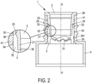
- the wringing device 1 according to the invention comprises first 2 and second 3 independent parts intended to be assembled with one another to form the wringing device 1 according to the invention, here by snapping into place the first part 2 in the second room 3.
- the first part 2 is generally cylindrical in shape, here, of axis revolution, a longitudinal axis XX of the first 2 and second 3 parts.
- the first part 2 has an upper end 26 comprising a rim forming a stop for placing in a reservoir neck a device for packaging and applying a fluid or pasty product.
- the first part 2 comprises an intermediate portion comprising on a radially external wall on which a first clamping boss 25 is provided.
- the first part 2 comprises a male part formed by a first skirt 21 of cylindrical shape.
- the first skirt 21 comprises, in the upper part, a first set 22,23,24 of means of locking 22,23,24,36,37 of the snap-fastening of the first part 2 in the second part 3.
- This first assembly is provided on an external wall of the first skirt 21 and comprises a first annular groove 24 delimited towards the bottom by a first bearing surface 23 extending perpendicular to a direction of engagement of the first part 2 in the second part 3.
- the direction of engagement of the first part 2 in the second part 3 is parallel to the longitudinal axis XX of the first 2 and second 3 parts, the direction of snap-in to achieve the assembly of the first 2 and second 3 parts being from top to bottom in the figures, as illustrated subsequently in the figures 1a to 1c .
- the first assembly comprises a first frustoconical surface 22 which continues through a cylindrical part up to a lower end of the first skirt 21.
- the first frustoconical surface 22 is positioned adjacent and downstream of the first bearing surface 23 in the direction of snapping of the first part 2 in the second part 3.
- the second part 3 is generally cylindrical in shape, here, of axis revolution, the longitudinal axis XX of the first 2 and second 3 parts. From top to bottom on the Figure 4 , the second part 3 comprises a female part formed of a second single skirt 32 of cylindrical shape, here of revolution of longitudinal axis XX, then a lower part comprising a deformable, therefore flexible, wiping lip 31.
- the second single skirt 32 is generally of complementary shape to a shape of the first skirt 21 and is intended to receive, during assembly of the first 2 and second 3 pieces, the first skirt 21 to slide along the longitudinal axis XX .
- the second skirt comprises a second set 36,37 of locking means 22,23,24,36,37 for the locking of the first part 2 in the second part 3.
- the second set comprises a second support surface 36 extending perpendicular to a direction of snapping of the first part 2 in the second part 3.
- the second assembly comprises a second frustoconical surface 37 which continues with a cylindrical part, forming part of the internal wall of the second skirt 32, up to a lower end of the second skirt 32 at the level of which a limit stop 38 is provided.
- the second bearing surface 36 and frustoconical surface 37 form a frustoconical annular groove in the internal wall of the second skirt 32.
- the second frustoconical surface 37 is positioned adjacent and downstream of the second bearing surface 36 in the direction of snapping of the first part 2 in the second part 3. Under the end of stroke stop 38, is the lower part comprising the deformable wiping lip 31.
- the second part 3 comprises a second clamping boss 33 provided to the right of the second skirt 32. More precisely here, the second clamping boss 33 is positioned to the right of the second support surface 36, therefore locking means.
- the second part 3 comprises a third clamping boss 34 on the external wall located on the second skirt 32.
- the third clamping boss 34 is located, along the longitudinal axis XX, under the second boss tightening 33.
- the second part 3 comprises means 35,351 for maintaining a geometry of the wiping lip 31.
- the means 35,351 for maintaining a geometry are provided on the external wall of the second part 3 and to the right of the wiping lip 31.
- the means for maintaining a geometry comprise a second annular groove 351 as well as an annular rim 35 forming a seal.
- the second annular groove 351 has a “V” shape in section.
- first 2 and second 3 pieces are brought one above the other so that their respective longitudinal axes XX coincide, the first skirt 21 being opposite the second skirt 32. Then, the first 2 and second 3 pieces are moved towards each other in the direction of the snap parallel to the longitudinal axis XX, the first skirt 21 penetrating into the second skirt 32, the external wall of the first skirt 21 being facing in sliding contact with the internal wall of the second skirt 32. The snapping movement of the first part 2 in the second part 3 continues until the second bearing surface 36 comes into place. house in the first annular groove 24 coming opposite the first support surface 23.
- the first frustoconical surface 22 deforms, during its passage, the upper end of the second skirt 32. Then, the end lower part of the first skirt 21 comes to rest on the limit stop 38. The locking is then carried out. Disassembly is prevented, that is to say a separation movement opposite to the direction of engagement of the first part 2 in the second part 3: the first support surface 23 then coming into surface support with the second surface d support 36, then locking the locking of the first skirt 21 in the second skirt 32.
- Such an assembly of the wringing device 1 according to the invention is facilitated by the fact that the first part 2 has a hardness greater than or equal to the second part 3.
- the drying device 1 can be handled, transported, put in bulk without risk of disassembly of the first 2 and second parts 3, whether in a box, or on an assembly line automatic or semi-automatic.
- the drying device 1 according to the invention as it has just been described is placed within a neck 41 of a reservoir 4 of a device for packaging and applying a product fluid or pasty.
- the means 35,351 for maintaining a geometry of the spin lip 31 are deformed without the geometry of the spin lip changing.
- the first 25, second 33 and third 34 clamping bosses rest deformed on an internal wall of the neck 41 ensuring complete tight hold of the wringing device 1 according to the invention in the neck 41 of the tank 4
- the annular rim 35 forming a seal, ensures sealing between at least the second annular groove 351 and the product contained in the tank 4.
Landscapes
- Packages (AREA)
- Drying Of Solid Materials (AREA)
- Cleaning Implements For Floors, Carpets, Furniture, Walls, And The Like (AREA)
- Containers And Packaging Bodies Having A Special Means To Remove Contents (AREA)
Claims (10)
- Auswringvorrichtung (1) für eine Vorrichtung zum Verpacken und Auftragen eines flüssigen oder pastösen Produkts, wobei die Auswringvorrichtung ein erstes (2) und ein zweites (3) unabhängiges Teil umfasst, wobei das erste Teil eine Härte aufweist, die größer oder gleich einer Härte des zweiten Teils ist, wobei das erste Teil einen Einsteckabschnitt umfasst, der durch eine erste Einfassung (21) gebildet wird, wobei das zweite Teil eine verformbare Auswringlippe (31) und einen Steckerabschnitt umfasst, der durch eine zweite Einfassung (32) gebildet wird und so angeordnet ist, dass er durch Einrasten die erste Einfassung des ersten Teils aufnimmt, wobei die Auswringvorrichtung ferner Verriegelungsmittel (22, 23, 24, 36, 37) für das Einrasten der ersten Einfassung in der zweiten Einfassung umfasst,
wobei die Auswringvorrichtung dadurch gekennzeichnet ist, dass das zweite Teil einen zweiten und einen dritten Festklemmvorsprung (34) umfasst, der auf einer Außenwand der zweiten Einfassung vorgesehen ist. - Auswringvorrichtung nach Anspruch 1, dadurch gekennzeichnet, dass die Verriegelungsmittel eine erste Anlagefläche (23) im rechten Winkel zu einer Einrastrichtung, die an der ersten Einfassung ausgebildet ist, und eine zweite Anlagefläche (36) im rechten Winkel zu einer Einrastrichtung, die an der zweiten Einfassung ausgebildet ist, umfassen, wobei die erste und die zweite Fläche bei einer Relativbewegung der beiden Teile in einer der Einrastrichtung entgegengesetzten Richtung aneinander zur Anlage kommen.
- Auswringvorrichtung nach Anspruch 2, dadurch gekennzeichnet, dass die Verriegelungsmittel eine erste kegelstumpfförmige Fläche (22) umfassen, die an der ersten Einfassung neben und stromabwärts von der ersten Anlagefläche in der Einrastrichtung vorgesehen ist.
- Auswringvorrichtung nach Anspruch 2 oder 3, dadurch gekennzeichnet, dass die Verriegelungsmittel eine zweite kegelstumpfförmige Fläche (37) umfassen, die an der zweiten Einfassung neben und stromabwärts von der zweiten Anlagefläche in der Einrastrichtung vorgesehen ist.
- Auswringvorrichtung nach einem der Ansprüche 1 bis 4, dadurch gekennzeichnet, dass die Verriegelungsmittel an einer Außenwand der ersten Einfassung und einer Innenwand der zweiten Einfassung angeordnet sind.
- Auswringvorrichtung nach einem der Ansprüche 1 bis 5, dadurch gekennzeichnet, dass das zweite Teil einen Endanschlag (38) für das erste Teil umfasst.
- Auswringvorrichtung nach einem der Ansprüche 1 bis 6, dadurch gekennzeichnet, dass das erste Teil einen ersten Festklemmvorsprung (25) umfasst, der an einer Außenwand des ersten Teils vorgesehen ist.
- Auswringvorrichtung nach einem der Ansprüche 1 bis 7, dadurch gekennzeichnet, dass der zweite Festklemmvorsprung in einer Linie mit den Verriegelungsmitteln positioniert ist.
- Auswringvorrichtung nach einem der Ansprüche 1 bis 8, dadurch gekennzeichnet, dass das zweite Teil ein Mittel zum Aufrechterhalten einer Geometrie (35, 351) der verformbaren Auswringlippe (31) umfasst.
- Auswringvorrichtung nach Anspruch 9, wobei das Mittel zum Aufrechterhalten einer Geometrie eine zweite ringförmige Nut (351) umfasst, die an einer Außenwand des zweiten Teils in einer Linie mit der verformbaren Auswringlippe vorgesehen ist.
Applications Claiming Priority (1)
| Application Number | Priority Date | Filing Date | Title |
|---|---|---|---|
| PCT/FR2019/051884 WO2021019131A1 (fr) | 2019-07-31 | 2019-07-31 | Dispositif d'essorage en deux parties |
Publications (3)
| Publication Number | Publication Date |
|---|---|
| EP4003091A1 EP4003091A1 (de) | 2022-06-01 |
| EP4003091B1 true EP4003091B1 (de) | 2023-11-01 |
| EP4003091C0 EP4003091C0 (de) | 2023-11-01 |
Family
ID=67909415
Family Applications (1)
| Application Number | Title | Priority Date | Filing Date |
|---|---|---|---|
| EP19766061.6A Active EP4003091B1 (de) | 2019-07-31 | 2019-07-31 | Zweiteilige auswringvorrichtung |
Country Status (3)
| Country | Link |
|---|---|
| US (1) | US12171320B2 (de) |
| EP (1) | EP4003091B1 (de) |
| WO (1) | WO2021019131A1 (de) |
Families Citing this family (1)
| Publication number | Priority date | Publication date | Assignee | Title |
|---|---|---|---|---|
| WO2023275581A1 (en) | 2021-06-30 | 2023-01-05 | Societe Industrielle De Matieres Plastiques | Applicator device for applying a fluid or pasty cosmetic product, obtained by moulding a biomaterial, and associated biomaterial |
Family Cites Families (8)
| Publication number | Priority date | Publication date | Assignee | Title |
|---|---|---|---|---|
| US3861810A (en) * | 1973-09-04 | 1975-01-21 | Bridgeport Metal Goods Mfg Co | Portal seal and wiper for product container |
| US5349972A (en) * | 1992-12-18 | 1994-09-27 | The Procter & Gamble Company | Dual wiper mascara package having residual chamber with bypass channel |
| US5597254A (en) | 1995-09-25 | 1997-01-28 | The Bridgeport Metal Goods Manufacturing Company | Wiper with vanes for use with viscous cosmetics |
| FR2865911B1 (fr) | 2004-02-06 | 2008-01-25 | Oreal | Dispositif de conditionnement et d'application comportant un organe d'essorage |
| FR3005835B1 (fr) | 2013-05-22 | 2015-05-29 | Montaigu Dev | Dispositif d'essuyage pour produit pateux, procede de montage associe |
| FR3028731B1 (fr) | 2014-11-20 | 2018-02-16 | L'oreal | Essoreur en deux pieces detachables |
| FR3057444A1 (fr) | 2016-10-13 | 2018-04-20 | L'oreal | Dispositif d'essorage en deux parties. |
| US11903478B1 (en) * | 2022-10-03 | 2024-02-20 | Elc Management Llc | Cosmetic product container |
-
2019
- 2019-07-31 EP EP19766061.6A patent/EP4003091B1/de active Active
- 2019-07-31 WO PCT/FR2019/051884 patent/WO2021019131A1/fr not_active Ceased
- 2019-07-31 US US17/629,669 patent/US12171320B2/en active Active
Also Published As
| Publication number | Publication date |
|---|---|
| EP4003091A1 (de) | 2022-06-01 |
| US12171320B2 (en) | 2024-12-24 |
| US20220287435A1 (en) | 2022-09-15 |
| EP4003091C0 (de) | 2023-11-01 |
| WO2021019131A1 (fr) | 2021-02-04 |
Similar Documents
| Publication | Publication Date | Title |
|---|---|---|
| FR2945283A1 (fr) | Dispositif de fixation pour fixer une pompe sur un col de reservoir | |
| EP2162663B1 (de) | Steckverbinder mit verbesserter aussenreinigung | |
| FR2996543A1 (fr) | Procede d'assemblage d'un dispositif d'emballage | |
| WO2015150646A1 (fr) | Ensemble de seringue anti-reflux | |
| EP2726215B1 (de) | Befestigungsring und spender für ein fliessfähiges produkt mit einem solchen ring | |
| EP4003091B1 (de) | Zweiteilige auswringvorrichtung | |
| FR2776991A1 (fr) | Dispositif de distribution de produits fluides | |
| FR2754037A1 (fr) | Dispositif de raccordement etanche de deux tubes metalliques bout a bout | |
| FR2978225A1 (fr) | Valve a fonctionnement selectif pour un recipient a usage biopharmaceutique. | |
| EP1370477B1 (de) | Flüssigkeitsspender | |
| EP3048061B1 (de) | Zylinderförmiger behälter mit korkenverschluss | |
| WO2005073093A2 (fr) | Dispositif de distribution de produit fluide | |
| EP1009682B1 (de) | Vorrichtung und verfahren zur halterung eines dosierorganes in einem behälter der abzugebende produkte enthält | |
| EP0286488B1 (de) | Luftdichtes Rauchleitungselement mit doppelten und wärmeisolierten Wänden | |
| FR2848194A1 (fr) | Organe de fixation pour fixer une pompe ou une valve sur un reservoir | |
| FR2799185A1 (fr) | Organe de fixation pour fixer un dispositif de distribution de produit fluide et distributeur de produit fluide comprenant un tel organe de fixation | |
| FR2976645A1 (fr) | Douille d'etancheite destinee a un passe-cable | |
| EP3867557B1 (de) | Anordnung mit einer rohrleitung und einer verbindungsvorrichtung zum verbinden eines rohres mit einer wand der rohrleitung | |
| EP0546911B1 (de) | Dichtungsring und Brennstofftank | |
| EP1915302B1 (de) | Abgabevorrichtung mit einer zur befestigung am hals eines fluidproduktbehälters ausgeführten anordnung | |
| FR2866634A1 (fr) | Bouchon composite | |
| EP1216196B1 (de) | Abgabevorrichtung mit einem aufgesteckten befestigungsring | |
| FR3056280A1 (fr) | Embout pour gaine tubulaire de matiere plastique souple | |
| EP0392908A1 (de) | Kupplung für Leitungen | |
| FR2546602A3 (fr) | Conduite en acier a emmanchement evase muni d'une garniture d'etancheite pour raccordement rapide |
Legal Events
| Date | Code | Title | Description |
|---|---|---|---|
| STAA | Information on the status of an ep patent application or granted ep patent |
Free format text: STATUS: UNKNOWN |
|
| STAA | Information on the status of an ep patent application or granted ep patent |
Free format text: STATUS: THE INTERNATIONAL PUBLICATION HAS BEEN MADE |
|
| PUAI | Public reference made under article 153(3) epc to a published international application that has entered the european phase |
Free format text: ORIGINAL CODE: 0009012 |
|
| STAA | Information on the status of an ep patent application or granted ep patent |
Free format text: STATUS: REQUEST FOR EXAMINATION WAS MADE |
|
| 17P | Request for examination filed |
Effective date: 20220131 |
|
| AK | Designated contracting states |
Kind code of ref document: A1 Designated state(s): AL AT BE BG CH CY CZ DE DK EE ES FI FR GB GR HR HU IE IS IT LI LT LU LV MC MK MT NL NO PL PT RO RS SE SI SK SM TR |
|
| DAV | Request for validation of the european patent (deleted) | ||
| DAX | Request for extension of the european patent (deleted) | ||
| STAA | Information on the status of an ep patent application or granted ep patent |
Free format text: STATUS: EXAMINATION IS IN PROGRESS |
|
| 17Q | First examination report despatched |
Effective date: 20230124 |
|
| GRAP | Despatch of communication of intention to grant a patent |
Free format text: ORIGINAL CODE: EPIDOSNIGR1 |
|
| STAA | Information on the status of an ep patent application or granted ep patent |
Free format text: STATUS: GRANT OF PATENT IS INTENDED |
|
| INTG | Intention to grant announced |
Effective date: 20230714 |
|
| GRAS | Grant fee paid |
Free format text: ORIGINAL CODE: EPIDOSNIGR3 |
|
| GRAA | (expected) grant |
Free format text: ORIGINAL CODE: 0009210 |
|
| STAA | Information on the status of an ep patent application or granted ep patent |
Free format text: STATUS: THE PATENT HAS BEEN GRANTED |
|
| AK | Designated contracting states |
Kind code of ref document: B1 Designated state(s): AL AT BE BG CH CY CZ DE DK EE ES FI FR GB GR HR HU IE IS IT LI LT LU LV MC MK MT NL NO PL PT RO RS SE SI SK SM TR |
|
| REG | Reference to a national code |
Ref country code: GB Ref legal event code: FG4D Free format text: NOT ENGLISH |
|
| REG | Reference to a national code |
Ref country code: CH Ref legal event code: EP |
|
| REG | Reference to a national code |
Ref country code: DE Ref legal event code: R096 Ref document number: 602019040617 Country of ref document: DE |
|
| REG | Reference to a national code |
Ref country code: IE Ref legal event code: FG4D Free format text: LANGUAGE OF EP DOCUMENT: FRENCH |
|
| U01 | Request for unitary effect filed |
Effective date: 20231103 |
|
| U07 | Unitary effect registered |
Designated state(s): AT BE BG DE DK EE FI FR IT LT LU LV MT NL PT SE SI Effective date: 20231108 |
|
| PG25 | Lapsed in a contracting state [announced via postgrant information from national office to epo] |
Ref country code: GR Free format text: LAPSE BECAUSE OF FAILURE TO SUBMIT A TRANSLATION OF THE DESCRIPTION OR TO PAY THE FEE WITHIN THE PRESCRIBED TIME-LIMIT Effective date: 20240202 |
|
| PG25 | Lapsed in a contracting state [announced via postgrant information from national office to epo] |
Ref country code: IS Free format text: LAPSE BECAUSE OF FAILURE TO SUBMIT A TRANSLATION OF THE DESCRIPTION OR TO PAY THE FEE WITHIN THE PRESCRIBED TIME-LIMIT Effective date: 20240301 |
|
| PG25 | Lapsed in a contracting state [announced via postgrant information from national office to epo] |
Ref country code: ES Free format text: LAPSE BECAUSE OF FAILURE TO SUBMIT A TRANSLATION OF THE DESCRIPTION OR TO PAY THE FEE WITHIN THE PRESCRIBED TIME-LIMIT Effective date: 20231101 |
|
| PG25 | Lapsed in a contracting state [announced via postgrant information from national office to epo] |
Ref country code: IS Free format text: LAPSE BECAUSE OF FAILURE TO SUBMIT A TRANSLATION OF THE DESCRIPTION OR TO PAY THE FEE WITHIN THE PRESCRIBED TIME-LIMIT Effective date: 20240301 Ref country code: GR Free format text: LAPSE BECAUSE OF FAILURE TO SUBMIT A TRANSLATION OF THE DESCRIPTION OR TO PAY THE FEE WITHIN THE PRESCRIBED TIME-LIMIT Effective date: 20240202 Ref country code: ES Free format text: LAPSE BECAUSE OF FAILURE TO SUBMIT A TRANSLATION OF THE DESCRIPTION OR TO PAY THE FEE WITHIN THE PRESCRIBED TIME-LIMIT Effective date: 20231101 |
|
| PG25 | Lapsed in a contracting state [announced via postgrant information from national office to epo] |
Ref country code: RS Free format text: LAPSE BECAUSE OF FAILURE TO SUBMIT A TRANSLATION OF THE DESCRIPTION OR TO PAY THE FEE WITHIN THE PRESCRIBED TIME-LIMIT Effective date: 20231101 Ref country code: PL Free format text: LAPSE BECAUSE OF FAILURE TO SUBMIT A TRANSLATION OF THE DESCRIPTION OR TO PAY THE FEE WITHIN THE PRESCRIBED TIME-LIMIT Effective date: 20231101 Ref country code: NO Free format text: LAPSE BECAUSE OF FAILURE TO SUBMIT A TRANSLATION OF THE DESCRIPTION OR TO PAY THE FEE WITHIN THE PRESCRIBED TIME-LIMIT Effective date: 20240201 Ref country code: HR Free format text: LAPSE BECAUSE OF FAILURE TO SUBMIT A TRANSLATION OF THE DESCRIPTION OR TO PAY THE FEE WITHIN THE PRESCRIBED TIME-LIMIT Effective date: 20231101 |
|
| PG25 | Lapsed in a contracting state [announced via postgrant information from national office to epo] |
Ref country code: CZ Free format text: LAPSE BECAUSE OF FAILURE TO SUBMIT A TRANSLATION OF THE DESCRIPTION OR TO PAY THE FEE WITHIN THE PRESCRIBED TIME-LIMIT Effective date: 20231101 |
|
| PG25 | Lapsed in a contracting state [announced via postgrant information from national office to epo] |
Ref country code: SK Free format text: LAPSE BECAUSE OF FAILURE TO SUBMIT A TRANSLATION OF THE DESCRIPTION OR TO PAY THE FEE WITHIN THE PRESCRIBED TIME-LIMIT Effective date: 20231101 |
|
| PG25 | Lapsed in a contracting state [announced via postgrant information from national office to epo] |
Ref country code: SM Free format text: LAPSE BECAUSE OF FAILURE TO SUBMIT A TRANSLATION OF THE DESCRIPTION OR TO PAY THE FEE WITHIN THE PRESCRIBED TIME-LIMIT Effective date: 20231101 Ref country code: SK Free format text: LAPSE BECAUSE OF FAILURE TO SUBMIT A TRANSLATION OF THE DESCRIPTION OR TO PAY THE FEE WITHIN THE PRESCRIBED TIME-LIMIT Effective date: 20231101 Ref country code: CZ Free format text: LAPSE BECAUSE OF FAILURE TO SUBMIT A TRANSLATION OF THE DESCRIPTION OR TO PAY THE FEE WITHIN THE PRESCRIBED TIME-LIMIT Effective date: 20231101 |
|
| REG | Reference to a national code |
Ref country code: DE Ref legal event code: R097 Ref document number: 602019040617 Country of ref document: DE |
|
| U20 | Renewal fee for the european patent with unitary effect paid |
Year of fee payment: 6 Effective date: 20240724 |
|
| PLBE | No opposition filed within time limit |
Free format text: ORIGINAL CODE: 0009261 |
|
| STAA | Information on the status of an ep patent application or granted ep patent |
Free format text: STATUS: NO OPPOSITION FILED WITHIN TIME LIMIT |
|
| 26N | No opposition filed |
Effective date: 20240802 |
|
| PG25 | Lapsed in a contracting state [announced via postgrant information from national office to epo] |
Ref country code: MC Free format text: LAPSE BECAUSE OF FAILURE TO SUBMIT A TRANSLATION OF THE DESCRIPTION OR TO PAY THE FEE WITHIN THE PRESCRIBED TIME-LIMIT Effective date: 20231101 |
|
| REG | Reference to a national code |
Ref country code: CH Ref legal event code: PL |
|
| PG25 | Lapsed in a contracting state [announced via postgrant information from national office to epo] |
Ref country code: CH Free format text: LAPSE BECAUSE OF NON-PAYMENT OF DUE FEES Effective date: 20240731 |
|
| PG25 | Lapsed in a contracting state [announced via postgrant information from national office to epo] |
Ref country code: IE Free format text: LAPSE BECAUSE OF NON-PAYMENT OF DUE FEES Effective date: 20240731 |
|
| U20 | Renewal fee for the european patent with unitary effect paid |
Year of fee payment: 7 Effective date: 20250728 |
|
| PGFP | Annual fee paid to national office [announced via postgrant information from national office to epo] |
Ref country code: GB Payment date: 20250722 Year of fee payment: 7 |
|
| PG25 | Lapsed in a contracting state [announced via postgrant information from national office to epo] |
Ref country code: RO Free format text: LAPSE BECAUSE OF FAILURE TO SUBMIT A TRANSLATION OF THE DESCRIPTION OR TO PAY THE FEE WITHIN THE PRESCRIBED TIME-LIMIT Effective date: 20231101 |
|
| PG25 | Lapsed in a contracting state [announced via postgrant information from national office to epo] |
Ref country code: CY Free format text: LAPSE BECAUSE OF FAILURE TO SUBMIT A TRANSLATION OF THE DESCRIPTION OR TO PAY THE FEE WITHIN THE PRESCRIBED TIME-LIMIT; INVALID AB INITIO Effective date: 20190731 |
|
| PG25 | Lapsed in a contracting state [announced via postgrant information from national office to epo] |
Ref country code: HU Free format text: LAPSE BECAUSE OF FAILURE TO SUBMIT A TRANSLATION OF THE DESCRIPTION OR TO PAY THE FEE WITHIN THE PRESCRIBED TIME-LIMIT; INVALID AB INITIO Effective date: 20190731 |