EP4003167B1 - Fingereinlagen für eine nagelfalzbildgebungsvorrichtung - Google Patents
Fingereinlagen für eine nagelfalzbildgebungsvorrichtung Download PDFInfo
- Publication number
- EP4003167B1 EP4003167B1 EP20843851.5A EP20843851A EP4003167B1 EP 4003167 B1 EP4003167 B1 EP 4003167B1 EP 20843851 A EP20843851 A EP 20843851A EP 4003167 B1 EP4003167 B1 EP 4003167B1
- Authority
- EP
- European Patent Office
- Prior art keywords
- finger
- insert
- wall portion
- nailfold
- wall
- Prior art date
- Legal status (The legal status is an assumption and is not a legal conclusion. Google has not performed a legal analysis and makes no representation as to the accuracy of the status listed.)
- Active
Links
Images


Classifications
-
- A—HUMAN NECESSITIES
- A61—MEDICAL OR VETERINARY SCIENCE; HYGIENE
- A61B—DIAGNOSIS; SURGERY; IDENTIFICATION
- A61B5/00—Measuring for diagnostic purposes; Identification of persons
- A61B5/0059—Measuring for diagnostic purposes; Identification of persons using light, e.g. diagnosis by transillumination, diascopy, fluorescence
- A61B5/0077—Devices for viewing the surface of the body, e.g. camera, magnifying lens
-
- A—HUMAN NECESSITIES
- A61—MEDICAL OR VETERINARY SCIENCE; HYGIENE
- A61B—DIAGNOSIS; SURGERY; IDENTIFICATION
- A61B5/00—Measuring for diagnostic purposes; Identification of persons
- A61B5/0059—Measuring for diagnostic purposes; Identification of persons using light, e.g. diagnosis by transillumination, diascopy, fluorescence
- A61B5/0082—Measuring for diagnostic purposes; Identification of persons using light, e.g. diagnosis by transillumination, diascopy, fluorescence adapted for particular medical purposes
-
- A—HUMAN NECESSITIES
- A61—MEDICAL OR VETERINARY SCIENCE; HYGIENE
- A61B—DIAGNOSIS; SURGERY; IDENTIFICATION
- A61B5/00—Measuring for diagnostic purposes; Identification of persons
- A61B5/02—Detecting, measuring or recording for evaluating the cardiovascular system, e.g. pulse, heart rate, blood pressure or blood flow
- A61B5/021—Measuring pressure in heart or blood vessels
- A61B5/022—Measuring pressure in heart or blood vessels by applying pressure to close blood vessels, e.g. against the skin; Ophthalmodynamometers
- A61B5/02233—Occluders specially adapted therefor
- A61B5/02241—Occluders specially adapted therefor of small dimensions, e.g. adapted to fingers
-
- A—HUMAN NECESSITIES
- A61—MEDICAL OR VETERINARY SCIENCE; HYGIENE
- A61B—DIAGNOSIS; SURGERY; IDENTIFICATION
- A61B5/00—Measuring for diagnostic purposes; Identification of persons
- A61B5/02—Detecting, measuring or recording for evaluating the cardiovascular system, e.g. pulse, heart rate, blood pressure or blood flow
- A61B5/026—Measuring blood flow
- A61B5/0261—Measuring blood flow using optical means, e.g. infrared light
-
- A—HUMAN NECESSITIES
- A61—MEDICAL OR VETERINARY SCIENCE; HYGIENE
- A61B—DIAGNOSIS; SURGERY; IDENTIFICATION
- A61B5/00—Measuring for diagnostic purposes; Identification of persons
- A61B5/145—Measuring characteristics of blood in vivo, e.g. gas concentration or pH-value ; Measuring characteristics of body fluids or tissues, e.g. interstitial fluid or cerebral tissue
- A61B5/1455—Measuring characteristics of blood in vivo, e.g. gas concentration or pH-value ; Measuring characteristics of body fluids or tissues, e.g. interstitial fluid or cerebral tissue using optical sensors, e.g. spectral photometrical oximeters
-
- A—HUMAN NECESSITIES
- A61—MEDICAL OR VETERINARY SCIENCE; HYGIENE
- A61B—DIAGNOSIS; SURGERY; IDENTIFICATION
- A61B5/00—Measuring for diagnostic purposes; Identification of persons
- A61B5/44—Detecting, measuring or recording for evaluating the integumentary system, e.g. skin, hair or nails
- A61B5/449—Nail evaluation, e.g. for nail disorder diagnosis
-
- A—HUMAN NECESSITIES
- A61—MEDICAL OR VETERINARY SCIENCE; HYGIENE
- A61B—DIAGNOSIS; SURGERY; IDENTIFICATION
- A61B5/00—Measuring for diagnostic purposes; Identification of persons
- A61B5/68—Arrangements of detecting, measuring or recording means, e.g. sensors, in relation to patient
- A61B5/6801—Arrangements of detecting, measuring or recording means, e.g. sensors, in relation to patient specially adapted to be attached to or worn on the body surface
- A61B5/6813—Specially adapted to be attached to a specific body part
- A61B5/6825—Hand
- A61B5/6826—Finger
-
- A—HUMAN NECESSITIES
- A61—MEDICAL OR VETERINARY SCIENCE; HYGIENE
- A61B—DIAGNOSIS; SURGERY; IDENTIFICATION
- A61B5/00—Measuring for diagnostic purposes; Identification of persons
- A61B5/70—Means for positioning the patient in relation to the detecting, measuring or recording means
- A61B5/702—Posture restraints
-
- A—HUMAN NECESSITIES
- A61—MEDICAL OR VETERINARY SCIENCE; HYGIENE
- A61B—DIAGNOSIS; SURGERY; IDENTIFICATION
- A61B2562/00—Details of sensors; Constructional details of sensor housings or probes; Accessories for sensors
- A61B2562/14—Coupling media or elements to improve sensor contact with skin or tissue
- A61B2562/146—Coupling media or elements to improve sensor contact with skin or tissue for optical coupling
-
- A—HUMAN NECESSITIES
- A61—MEDICAL OR VETERINARY SCIENCE; HYGIENE
- A61B—DIAGNOSIS; SURGERY; IDENTIFICATION
- A61B2562/00—Details of sensors; Constructional details of sensor housings or probes; Accessories for sensors
- A61B2562/16—Details of sensor housings or probes; Details of structural supports for sensors
- A61B2562/164—Details of sensor housings or probes; Details of structural supports for sensors the sensor is mounted in or on a conformable substrate or carrier
-
- A—HUMAN NECESSITIES
- A61—MEDICAL OR VETERINARY SCIENCE; HYGIENE
- A61B—DIAGNOSIS; SURGERY; IDENTIFICATION
- A61B2562/00—Details of sensors; Constructional details of sensor housings or probes; Accessories for sensors
- A61B2562/16—Details of sensor housings or probes; Details of structural supports for sensors
- A61B2562/168—Fluid filled sensor housings
-
- A—HUMAN NECESSITIES
- A61—MEDICAL OR VETERINARY SCIENCE; HYGIENE
- A61B—DIAGNOSIS; SURGERY; IDENTIFICATION
- A61B5/00—Measuring for diagnostic purposes; Identification of persons
- A61B5/145—Measuring characteristics of blood in vivo, e.g. gas concentration or pH-value ; Measuring characteristics of body fluids or tissues, e.g. interstitial fluid or cerebral tissue
- A61B5/14546—Measuring characteristics of blood in vivo, e.g. gas concentration or pH-value ; Measuring characteristics of body fluids or tissues, e.g. interstitial fluid or cerebral tissue for measuring analytes not otherwise provided for, e.g. ions, cytochromes
-
- G—PHYSICS
- G06—COMPUTING OR CALCULATING; COUNTING
- G06V—IMAGE OR VIDEO RECOGNITION OR UNDERSTANDING
- G06V40/00—Recognition of biometric, human-related or animal-related patterns in image or video data
- G06V40/10—Human or animal bodies, e.g. vehicle occupants or pedestrians; Body parts, e.g. hands
- G06V40/12—Fingerprints or palmprints
- G06V40/1341—Sensing with light passing through the finger
Definitions
- WBCs White blood cells
- leukocytes or leucocytes are cells of the immune system that are involved in protecting the body against both infectious disease and foreign invaders.
- WBCs can exist not only in the blood, but also in the lymphatic system and tissues. Some conditions can trigger a response in the immune system and cause an increase in the number of WBCs (also referred to as WBC count). Other conditions can affect the production of WBCs by the bone marrow or the survival of existing WBCs in the circulation system. As these examples illustrate, various conditions can cause a change (either an increase or a decrease) of the number of circulating WBCs.
- WBC count can be a relevant physiological parameter for the diagnosis, monitoring, and/or treatment of various conditions including, but not limited to, bacterial and viral infections (e.g., pneumonia or meningitis), bone marrow functionality associated with chemotherapy toxicity, and hematologic proliferative processes such as leukemia.
- bacterial and viral infections e.g., pneumonia or meningitis
- bone marrow functionality associated with chemotherapy toxicity
- hematologic proliferative processes such as leukemia.
- the finger well 110 of the imaging device 100 accommodates the user's finger 120 in the imaging device 100 and contains optical immersion oil.
- the finger well 110 also includes a flat optical window 130, to allow for illumination and for time-lapse microscopic imaging of the nailfold region of the user's finger 120 through the optical window 130.
- the rigid housing that forms the finger well 110 can provide enough space to accommodate different finger sizes, but can leave a gap between the finger and the housing, allowing space for the finger to move easily.
- a finger insert for a nailfold imaging device includes a housing an opening to receive a finger of a subject.
- the housing defines a landing region abuts against a distal phalange of the finger of the subject when the finger is placed into the finger insert via the opening.
- the housing holds a liquid to facilitate imaging of a nailfold of the finger of the subject, such that at least the distal phalange of the finger is immersed in the liquid when the liquid is present in the finger insert and as the finger is placed into the finger insert via the opening.
- the housing includes a first wall and a second wall, with the second wall being optically transparent to facilitate imaging of the nailfold of the finger.
- the finger insert further includes a deformable pad positioned on at least a portion of the first wall, to form an open-pore structure that fills a gap between the first wall and the finger of the user when the finger is inserted into the finger insert, and to reduce trapped air in the liquid when the liquid is present in the finger insert, during insertion and movement of the finger in the finger insert.
- a system that does not form part of the claimed invention, includes a finger imaging device including a light source, a detector, and a receptacle including an imaging window.
- the light source and the detector are optically coupled to the imaging window.
- the system also includes a finger insert, the finger insert being disposable in the receptacle.
- the finger insert includes a housing defining an opening an opening to receive a finger of a subject, and further defining a landing region that abuts against a distal phalange of the finger of the subject when the finger is placed into the finger insert via the opening, to hold a liquid to facilitate imaging of a nailfold of the finger of the subject.
- the housing includes a first wall and a second wall, the second wall being optically transparent to facilitate imaging of the nailfold of the finger via the light source and detector.
- the finger insert further includes a deformable pad positioned on at least a portion of the first wall, to form an open-pore structure that fills a gap between the first wall and the finger of the user when the finger is inserted into the finger insert, and to reduce trapped air in the liquid when the liquid is present in the finger insert, during insertion and movement of the finger in the finger insert.
- a kit that does not form part of the claimed invention, includes a finger imaging device including a light source, a detector, and a receptacle including an imaging window. The light source and the detector are optically coupled to the imaging window.
- the kit also includes a set of finger inserts, each finger insert of the set of finger inserts being disposable in the receptacle such that at least a section of the second wall of that finger insert is in optical communication with the imaging window when that finger insert is disposed in the receptacle.
- a first finger insert of the set of finger inserts is different from a finger insert apparatus of the set of finger inserts in one or more of a length of the housing along its longitudinal axis, and an average cross-sectional area of a curved portion of the first wall.
- a method includes receiving a finger of a user in a finger insert disposed in a nailfold imaging device.
- the finger insert includes a housing defining an opening an opening to receive a finger of a subject, and further defining a landing region abuts against a distal phalange of the finger of the subject when the finger is placed into the finger insert via the opening, to hold a liquid to facilitate imaging of a nailfold of the finger of the subject.
- At least the distal phalange of the finger is immersed in the liquid when the liquid is present in the finger insert and as the finger is placed into the finger insert via the opening.
- the housing including a first wall and a second wall, the second wall being optically transparent to facilitate imaging of the nailfold of the finger.
- the finger insert also includes a deformable pad positioned on at least a portion of the first wall, to form an open-pore structure that fills a gap between the first wall and the finger of the user when the finger is inserted into the finger insert, and to reduce trapped air in the liquid when the liquid is present in the finger insert, during insertion and movement of the finger in the finger insert.
- the method further includes imaging a nailfold portion of the finger via the wall portion of the finger insert using the nailfold imaging device.
- a finger insert as described herein can include and/or encompass a removable piece that is inserted into a nailfold imaging device before a measurement (e.g., imaging, video recording) starts, and is removed afterwards.
- the finger insert may be single-use and disposable, or reusable.
- the finger insert can be designed to engage with the nailfold imaging device ergonomically and securely, such that it provides a sturdy yet comfortable support for the finger while in use.
- the finger insert can include an incorporated optical window to ensure that the optical path between the imaging and illumination optics is clean and transparent each time.
- Immersion oil can be pre-filled into the finger insert to prevent reuse and contamination of immersion oils with particulates.
- the insert accommodates different finger sizes through variable internal geometry, with different sized inserts available (e.g., small-long, small-short, medium-long, medium-short, large-long, large-short).
- the finger insert includes one or more flexible spacers to effectively and comfortably fill a gap that may be present between the rigid body of the finger insert and the finger of the subject.
- the flexible spacers may be implemented as rubber cylinders extruded from (and extending from) the walls of the body of the finger insert.
- the open-pore structure of the rubber cylinders significantly mitigates the trapping of air which would otherwise occur with semi-closed-pore structures like sponges, that would produce air bubbles in the immersion oil under the typical compression that occurs during inserting and movement of the finger.
- FIG. 2 illustrates aspects of finger geometry that can be considered when designing inventive finger inserts according to the present disclosure to accommodate various finger sizes.
- cross-sectional area and shape along the length of the finger e.g., see the cross-sectional profiles 210, 220, 230 along the length of the finger
- Excessive force on the finger can result in restriction of blood flow (that could in turn impede measurement made on the nailfold capillaries of that finger), and too little support or restriction would reduce the necessary constraint for minimizing involuntary movement.
- a second example aspect can be the length of the finger from fingertip to nailfold (e.g., the length 240), which is typically the same or similar to the fingernail length of that finger.
- the finger insert is designed such that the fingertip registers with the bottom of the insert, so that the distance between the end of the finger and the nailfold affects how high the nailfold sits in the well of the finger insert. This can be significant since the nailfold would need to fall within a region where the nailfold imaging device is able to image the nailfold region.
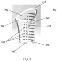
- FIG. 3 illustrates an example finger insert 310.
- the insert 310 can include a housing 312, a plate 330 (that may or may not be integrally formed with the housing), and multiple spacers 340 that are deformable by a user's finger when inserted into the insert 310.
- the housing 312 and the plate 330 can be made from a substantially rigid, inelastic material such as a transparent thermoplastic (e.g. Poly(methyl methacrylate), or PMMA).
- the spacers can be made from an elastic, deformable material such as a silicone. In some cases, the material of the spacers can be optically transparent, while it can be absorbing in some other cases.
- the housing can include a top end 314 that has an opening to receive the user's finger, and a bottom end 316.
- a body 318 of the housing 312 is disposed and/or otherwise formed between the top end 314 and the bottom end 316, and can hold an immersion oil.
- the immersion oil can be selected to have a refractive index (e.g., a RI of about 1.51) that is similar to that of the housing and/or the dermis of the finger, to facilitate the nailfold imaging.
- the housing 312 can be sized to hold enough immersion oil such that at least the distal phalange of the finger is fully immersed in it.
- the housing 312 can include a curved portion 320 and a wall portion 322.
- the wall portion 322 can be optically transparent and substantially flat to prevent spurious reflections that can arise due to the illumination. In some cases the wall portion 322 can be curved, or another suitable form to conform to the nailfold imaging device during use.
- the curved portion 320 can have a cross-sectional area (CSA) that (in at least a portion of the curved portion 320) continuously or discontinuously changes from the top end 314 to the bottom end 316. As explained above in connection with FIG. 2 , such a CSA profile can accommodate for the typical changes in CSA of a user's finger along its length, towards the nailfold region.
- the curved portion 320 can be optically transparent, or absorbing to prevent reflection of a light beam from the light source of the nailfold imaging device.
- the CSA can vary from about 3 cm 2 to about 1 cm 2 from the top end 314 to the bottom end 316.
- the depth of the housing from the top end 314 to the bottom end 316 can vary from about 10 mm to about 20 mm.
- the plate 330 is disposed, attached, coupled and/or otherwise present at the bottom end 316 of the housing 312 and can abut against a distal phalange of the finger of the subject to position the finger for imaging.
- the plate 330 and the bottom end 316 can form a fluid-tight seal to prevent the immersion oil from leaking.
- multiple, deformable spacers 340 can be positioned, attached, formed, and/or otherwise disposed on the curved portion 320.
- the number, size, shape, and/or other aspects of the spacers 340 can be useful for forming an open-pore structure that can effectively and significantly fill a gap between the curved portion 320 and the finger of the user when inserted.
- the spacers 340 can be designed to accommodate a variety of finger geometries, with the goal of providing support to minimize unintentional movement during the measurement.
- the open-pore structure of the spacers 340 even when deformed due to the pressure from the user's finger, significantly reduces or eliminates trapped air in the immersion oil when the user's finger is inserted into the insert, or moved around within the insert.
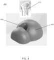
- FIG. 4 illustrates a system 400 that includes a finger insert 410, which can be structurally and/or functionally similar to the insert 310.
- the system also includes a nailfold imaging device 450, which can be similar to such devices disclosed in the related U.S. patent publication nos. 2016/0148038 and 2019/0139221 .
- the insert 410 is inserted into a receptacle 420 of the device 450 to achieve a firm mating to allow for rigid mechanical coupling of the insert 410 and device 450, and to achieve a stable optical alignment for imaging the nailfold region of a finger in the insert 410.
- FIG. 5 generally illustrates an example nailfold imaging device 1100 (also referred to as a "WBC detection and analysis system") that includes a finger holder 1110 with a receptacle 1112 (also referred to as a "finger hold").
- An imaging window 1114 is formed within the receptacle 1112 can be in optical communication with the interior of the insert 410 via its wall portion to permit nailfold imaging of the user's finger in the inert.
- the device 1100 can include an imager/imaging setup 1120 that includes a light source (not shown) to illuminate the user's nailfold region within the insert 410 via the window 1114.
- the imager 1120 includes a focusing optic 1122 to collect light reflected or scattered from the finger and detector 1124 to receive the reflected or scattered light so as to form images of the finger.
- the device 1100 further includes a processor 1130 operably coupled to the imager 1120 and a memory 1140 operably coupled to the processor 1130.
- the memory 1140 is encoded with processor-executable instructions, which, when executed by processor 1130, may perform the methods described in the '038 and/or the '221 publications to analyze images received from the imager 1120.
- the device 1100 also includes a display 1150, which can display the images or videos taken by the imager 1120 and/or data associated with WBC events detected by the processor 1130.
- FIG. 7A illustrates another insert design, where insert 710 does not include the wall portion of the insert 310, and wherein the plate 730 has a relatively more rounded profile than the plate 330 to better conform to a user's fingertip, and to prevent inadvertent movement. In some cases, however, the plate 730 can be substantially flat.
- the lack of the wall portion can provide for fewer coupling layers between the device and the user's finger, and a simplified design relative to that of the insert 310.
- Such a setup can require removal and replacement of immersion oil within the receptacle of the device 750, periodic cleaning to avoid accumulation of dirt and/or dust, and replacement of the imaging window (e.g., the window 1114) due to potential scratching over time, which can deteriorate imaging.
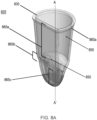
- FIGS. 8A-8D illustrates a housing 820 of another finger insert design.
- the housing 820 includes an opening 830 through which a user can insert their finger into the housing.
- the distal phalange of the finger of the user can land on and/or abut against a landing region 840 of the housing 820.
- the landing region 840 can generally form, at least in part, a curved socket that conforms to the shape of the tip of a typical human finger.
- the curved socket can be positioned to ensure that the user's finger lands landed approximately centered about a longitudinal axis A-A' of the housing 820 in the view illustrated in FIG. 8B .
- the housing 820 can form a fluid-tight seal to hold a substance, e.g., an immersion oil or any other suitable liquid, to facilitate imaging.
- the immersion oil can have a refractive index (e.g., a RI of about 1.51) that is similar to that of the housing 820 and/or the dermis of the finger, to facilitate the nailfold imaging.
- the housing 820 can be sized such that at least the distal phalange of the user's finger is within the housing 820, and can be immersed in the substance, to permit imaging of the nailfold region.
- a length of the housing such as along the axis A-A', can be from about 1 cm to about 7 cm, including all values and sub-ranges in between.
- the housing 820 can be wholly or partly formed of an inelastic material such as, for example such as an optically transparent thermoplastic (e.g. Poly(methyl methacrylate), or PMMA) glass (e.g., amorphous or crystalline), quartz (e.g., including Herkimer diamond, rock crystal, etc.), and/or the like.
- an optically transparent thermoplastic e.g. Poly(methyl methacrylate), or PMMA
- PMMA poly(methyl methacrylate), or PMMA glass
- quartz e.g., including Herkimer diamond, rock crystal, etc.
- imaging of the nailfold region can encompass imaging of at least some portion of the nailfold. For example, it is not required that the entire nailfold of the finger be exposed and/or otherwise available for imaging (e.g., due to the size of the imaging window of the imaging device), and imaging of the exposed portion of the nailfold can be sufficient for the purposes laid out herein, including for white blood cell measurements.
- the first wall 850 can define a wall portion 860a, a wall portion 860b adjacent to the wall portion 860a, and a wall portion 860c adjacent to the wall portion 860b.
- the second wall portion can define a wall portion 865a, a wall portion 865b adjacent to the wall portion 865a, and a wall portion 865c adjacent to the wall portion 865b.
- These wall portions 865a, 865b, 865c, 860a, 860b, and 860c are sometimes also referred to here as a first wall portion, a second wall portion, a third wall portion, a fourth wall portion, a fifth wall portion, and a sixth wall portion, respectively.
- an edge/side of the wall portion 865a can form a portion of the rim of the opening 830, as best illustrated in FIG. 8A .
- the wall portion 865a can be substantially optically transparent to permit imaging of the nailfold region of the user's finger.
- the wall portion 865a can be substantially flat in its entirety, or in part such as, for example, towards the wall portion 865b.
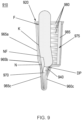
- a knuckle of the user's finger e.g., the distal interphalangeal joint, can abut or lie against the wall portion 865a, as illustrated in FIG. 9 for the knuckle K, and described in greater detail later.
- the wall portion 865a can be angled with respect to, and/or form an angle with, the wall portion 865b at an angle ⁇ 1, which can be about 10°, about 15°, about 20°, about 25°, about 30°, including all values and sub-ranges in between.
- the wall portion 865c in turn can be angled with respect to, and/or form an angle with, the wall portion 865b at an angle ⁇ 2, which can be about 10°, about 15°, about 20°, about 25°, about 30°, including all values and sub-ranges in between.
- an edge/side of the wall portion 860a can form a remaining portion of the rim of the opening 830, such that the wall portions 860a, 860b collective form and/or otherwise define the opening 830.
- the opening 830 can be generally circular, though in other cases (not shown), the opening 830 can be oval, elliptical, and/or the like.
- Factors affecting the shape of the opening 820 can include, but are not limited to, ease of holding, inserting, and/or removing the housing 820, ease of sealing the opening 820 with a fluid-tight seal, the shape of an opening of a receptacle in a finger insert device that receiving the insert 810, ease of fabrication (e.g., during injection molding), and/or the like.
- the wall portion 860a can be curved.
- the cross-sectional area defined by the wall portion 860a can be substantially the same, or continuously decrease, from the opening 830 towards the wall portion 860b.
- the cross-sectional area can be, for example, about 2 cm 2 to about 4 cm 2 at the opening 830.
- the cross-sectional area defined by the wall portion 860a can decrease in a periodic or step-wise manner, such that the wall portion 860a defines two or more different cross-sectional areas from the opening 830 towards the wall portion 860b.
- the wall portion 860a can be substantially optically transparent, e.g., similar to the wall portion 865a.
- the wall portion 860a can be partially transparent, and/or composed of a light absorbing material, to prevent undesirable reflection of the excitation light during nailfold imaging.
- the wall portions 860b, 860c can collectively form and/or otherwise define the landing region that receives the end of the user's finger during use, as best illustrated in FIGS. 8A , 8C .
- the insert 910 includes a pad 975 that is affixed, glued, and/or otherwise positioned on the first wall 850, e.g., wholly, or at least partly on the wall portion 860a of the first wall.
- the deformable pad 975 includes a base layer 985 and multiple spacers 980 formed on the base layer. In some cases, the base layer 985 can be absent, and the spacers 980 can be formed directly on the first wall 850.
- the pad 975 can be wholly deformable, e.g., both the base layer 985 and the spacers 980 can be composed of a deformable material such as, for example, silicone or a silicone-based material.
- the base layer 985 and the spacers 980 can be composed of different materials of different deformability such as, for example, a silicone, a nitrile, a neoprene and/or other rubbers, combinations thereof, and/or the like.
- the pad 975 can be partially deformable such as, for example, having the base layer 985 be composed of a rigid, inelastic material while the spacers 980 are composed of a deformable material.
- the deformability of the spacers 980 can elastically deform upon insertion of the user's finger F, to press the finger F against the second wall 950.
- Each spacer 980 can be suitably shaped, sized, and laid out in an open-pore structure to maintain separation between adjacent spacers in the absence of deformation. Further, the open-pore structure of the spacers 980 can reduce the formation of air bubbles and/or generally reduce/eliminate any trapped air in the immersion liquid that may have entered the insert 910 during insertion or movement of the user's finger. Such trapped air can interfere with nailfold imaging and lead to artifacts.
- the spacer 980 can be generally columnar or cylindrical in form, including forms such as, for example, right circular cylinders, oblique cylinders, cones, oblique cones, frustums (e.g., pyramidal, or conical), prismatic (e.g., elongated prisms, truncated elongated prisms, fin-like), and/or combinations thereof.
- the spacers 980 can be substantially frustoconical in form, having a larger cross-sectional radius towards the base layer 985/the wall portion 975.
- the number of spacers can be 2, 10, 20, 50, 100, 150, 200, or more than 200, including all values and sub-ranges in between.
- FIG. 9 also illustrates how the wall portions 960c, 965c cooperate to define and/or enclose a nail space 970 that can accommodate a nail N of the finger F.
- the insert 910 can accommodate, i.e., receive in a secure fit manner, fingers of users with longer nails that extend beyond the distal end (i.e., the fingertip, also sometimes referred to as the distal phalange) of the user's finger.
- the distal end DP of the finger lands and rests on the landing region 940, and is pushed against the wall 950 by the pad 980.
- the angle ⁇ 1 formed between the wall portions 965a, 965b the knuckle/joint K of the finger lands on the wall portion 965a, while the nail N of the finger lands on the region 965b, resulting in a reduction of elimination of any interaction or contact between the wall portion 965a and the nailfold region NF of the finger F.
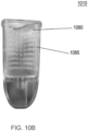
- FIGS. 10A , 10B show a fabricated, example finger insert 1010 (e.g., structurally and/or functionally similar to the inserts 810, 910) with a deformable pad that includes both a base layer 1085 and spacers 1080 formed on the base layer.
- the base layer 1085 and the spacers 1080 here are integrally formed, of the same deformable material.
- the spacers 1080 are substantially conical in form.
- the finger insert 1010 is wholly transparent in this example, and the wall portion 1060a is substantially frustoconical, i.e., it has a decreasing cross-section area from the opening inwards.
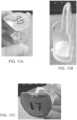
- FIGS. 11A-11C show various views of finger inserts (e.g., structurally and/or functionally similar to any of the inserts described herein) having immersion oil disposed therein, and a fluid-tight seal at the opening.
- the labeling, shown in FIGS. 11A and 11C can indicate unit numbers and/or a scale associated with, for example, variation in geometry of the structures of the finger insert and/or the pad, volume and/or nature of the liquid contained within, and/or the like.
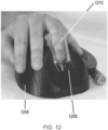
- FIG. 12 shows a finger insert 1210 (e.g., structurally and/or functionally similar to the inserts described herein) during use with a nailfold imaging device 1205, and with a user's finger inserted therein.
- a receptacle 1208 of the device 1205 can receive the insert 1210 in a mating-fit manner.
- the device 1205 can be configured to perform nailfold imaging of the user's finger as generally described in the '038, '221 publications.
- kits that include multiple finger inserts (e.g., such as any finger insert described here).
- the finger inserts of the kit can be different from one other in any matter such as, but not limited to, a length of the housing along its longitudinal axis (e.g., along the axis A-A'), an average cross-sectional area of a curved wall portion (e.g., the wall portion 860a), variations in the geometry and/or mechanical properties of the pad (e.g., the pad 975).
- each finger insert can have the liquid (e.g., a sterile immersion oil) already included therein, and a leak-proof covering over its opening, similar to shown in FIGS. 11A-11C .
- the kit can include the nailfold imaging device itself, such as the device 1205, the device 1100 in FIG. 5 , and/or as generally described in the ⁇ 038, '221 publications.
- an imaging device similar to that illustrated in FIG. 5 for example can include a light source to illuminate the nailfold region through the second wall (e.g., the wall 855), and a detector to receive the optical signal/beam from the nailfold region.
- the imaging device can also include a receptacle (e.g., the receptacle 1208) sized and shaped to receive the finger inserts in any suitable mating manner.
- a system can include one or more finger inserts, and a nailfold imaging device as described herein.
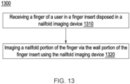
- FIG. 13 illustrates a method 1300, such as for nailfold imaging.
- the method 1300 includes, at 1310, receiving a finger of a user in a finger insert (e.g., structurally and the insert 810, 910, 1010, and/or 1210) disposed in a nailfold imaging device (e.g., the device of FIG. 5 , FIG. 12 , and/or as generally described in the '038, '221 publications).
- a finger insert e.g., structurally and the insert 810, 910, 1010, and/or 12
- a nailfold imaging device e.g., the device of FIG. 5 , FIG. 12 , and/or as generally described in the '038, '221 publications.
- the finger insert can include a housing (e.g., the housing 820) that defines an opening (e.g., the opening 830) to receive a finger of a subject, and further defining a landing region (e.g., the region 840) that abuts against a distal phalange of the finger of the subject when the finger is placed into the finger insert via the opening.
- the housing can hold a liquid (e.g., an immersion oil) to facilitate imaging of a nailfold of the finger of the subject.
- the method 1400 can encompass adding the liquid to the finger insert prior to step 1310.
- the housing including a first wall (e.g., the wall 850) and a second wall (e.g., the wall 855), the second wall being optically transparent to facilitate imaging of the nailfold of the finger.
- the method 1300 can also include inserting the finger insert into a receptacle of the nailfold imaging device.
- the nailfold imaging device includes a light source and a detector, and the receptacle includes an imaging window such that the light source and the detector are optically coupled to the imaging window.
- the method also includes, at step 1320, imaging a nailfold portion of the finger via the wall portion of the finger insert using the nailfold imaging device.
- the imaging can include includes imaging the portion of the finger with the light source and detector via the imaging window and via the second wall of the finger insert.
- an insert for imaging a human toe can be shaped and sized according to the considerations laid out herein, and accounting for the specific anatomy of the human toe.
- One such consideration could be, for example, that toes of the human feet do not splay out to the same extent that fingers do, so a toe insert will likely have to be sized to prevent excessive and painful separation between the user's toes.
- Another consideration can be, for example, that toes display wider variability in size than fingers, so a toe insert may need to be designed specifically for one or fewer than all toes of a user's foot.
- aspects disclosed herein can be useful for imaging other regions of a user's fingers outside the nailfold region (e.g., anywhere on the middle phalanx of the user's finger), other regions of a user's toes outside the nailfold region (e.g., anywhere on the middle phalanx of the user's finger or user's toe), and/or the like.
- Patient's fingers can be used to perform a number of different physiological and healthcare tests, including, for example, the noninvasive measurement of a patient's white blood cell or neutrophil levels. These measurements often require or depend on stabilizing the finger for a certain period of time, and keeping it repeatedly within a predefined Region of Interest (ROI) in order to successfully carry out the measurement. Demonstrated here is how a custom, disposable "finger insert" can meet these needs. A series of studies were on a sample size of nine naive subjects to estimate the critical target ROI for such blood measurements, as well as the intra-subject and inter-subject variability in finger positioning within that ROI.
- ROI Region of Interest
- FOV Field Of View
- naive users would be able to use the finger insert intuitively, that the finger can be placed comfortably into the finger insert, and that the nailfold should fall within the correct target zone or ROI for every measurement.
- the finger insert should guide the user's finger to the bottom extrusion within the finger insert as well as centering the finger and making the user comfortable.
- the knuckle of each finger measured should have minor contact with the inside face of the finger insert to stabilize the finger and avoid excessive pressure surrounding the nailfold, which could hinder blood flow and limit the ability to collect physiological and healthcare measurements from it.
- the ROI center should remain still to capture the measurement, so a padding in the finger insert was designed (the base layer 1085 and the spacers 1080 illustrated in FIGS. 10A , 10B ) to secure the finger in place during the measurement with minimal vibration relative to the imaging system.
- the employed imaging system yields a 7 mm by 5 mm FOV, so the center of the ROI should be captured in this FOV.
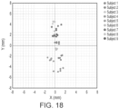
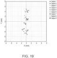
- Each dot on FIGS. 16, 17 represents one data point from one finger of each subject where the ROI center falls.
- the maximum range of data falls between about 12mm in the vertical direction and roughly 5mm in the horizontal direction across all subjects.
- the data indicates that the finger insert condenses the nailfold ROI centers of the sample size to a range where one can take measurements with confidence. Based on measuring the center of the nailfold, it was found that each finger has roughly a 2 by 2mm span for repeatability on the same location, as discernable from FIGS. 18 , 19 . By taking the center of the nailfold and measuring outwards until the end of the nailfold ( FIG. 15 ), the study found that the average width of nailfolds is 8.2mm among the subjects. There is a minimal amount of translation in the vertical direction due to the geometry of the common nailfold.
- Intra-subject data shows about a 4-5mm variation in the Y-direction across the index, middle, and ring fingers ( FIG. 20 ).
- the most dispersed data corresponded to the left middle finger of one particular subject, and all data points fall within 4 mm by 3 mm FoV.
- the largest ROI encompassing all finger positions from our data was about 9.5 mm by 5.5 mm, and the largest FoV where one could image the nailfold area was 8 mm by 6 mm ( FIG. 21 ).
- pre-calibration that is, by adjusting the Y position of the finger disposable beforehand to compensate for each user's finger length, we can image most nailfold areas within an 8 mm by 6 mm FoV.
- a reference to "A and/or B", when used in conjunction with open-ended language such as “comprising” can refer, in one embodiment, to A only (optionally including elements other than B); in another embodiment, to B only (optionally including elements other than A); in yet another embodiment, to both A and B (optionally including other elements); etc.
- the phrase "at least one,” in reference to a list of one or more elements, should be understood to mean at least one element selected from any one or more of the elements in the list of elements, but not necessarily including at least one of each and every element specifically listed within the list of elements and not excluding any combinations of elements in the list of elements.
- This definition also allows that elements may optionally be present other than the elements specifically identified within the list of elements to which the phrase "at least one" refers, whether related or unrelated to those elements specifically identified.
- At least one of A and B can refer, in one embodiment, to at least one, optionally including more than one, A, with no B present (and optionally including elements other than B); in another embodiment, to at least one, optionally including more than one, B, with no A present (and optionally including elements other than A); in yet another embodiment, to at least one, optionally including more than one, A, and at least one, optionally including more than one, B (and optionally including other elements); etc.
Landscapes
- Health & Medical Sciences (AREA)
- Life Sciences & Earth Sciences (AREA)
- Physics & Mathematics (AREA)
- Heart & Thoracic Surgery (AREA)
- Molecular Biology (AREA)
- Veterinary Medicine (AREA)
- Public Health (AREA)
- General Health & Medical Sciences (AREA)
- Biophysics (AREA)
- Pathology (AREA)
- Engineering & Computer Science (AREA)
- Biomedical Technology (AREA)
- Animal Behavior & Ethology (AREA)
- Medical Informatics (AREA)
- Surgery (AREA)
- Cardiology (AREA)
- Vascular Medicine (AREA)
- Physiology (AREA)
- Dermatology (AREA)
- Physical Education & Sports Medicine (AREA)
- Dentistry (AREA)
- Ophthalmology & Optometry (AREA)
- Hematology (AREA)
- Spectroscopy & Molecular Physics (AREA)
- Optics & Photonics (AREA)
- Measurement Of The Respiration, Hearing Ability, Form, And Blood Characteristics Of Living Organisms (AREA)
- Measuring Pulse, Heart Rate, Blood Pressure Or Blood Flow (AREA)
Claims (15)
- Fingereinlage (310), die dafür ausgelegt ist, in eine Nagelfalzbildgebungsvorrichtung einzugreifen, wobei die Fingereinlage umfasst:ein Gehäuse (312), das eine Öffnung (314) definiert, die so gestaltet ist, dass sie einen Finger einer Testperson aufnimmt, und das ferner einen Landebereich definiert, der so gestaltet ist, dass er gegen ein distales Glied des Fingers der Testperson stößt, wenn der Finger über die Öffnung in die Fingereinlage gelegt wird, wobei das Gehäuse eine flüssigkeitsdichte Abdichtung bildet, die so gestaltet ist, dass sie eine Flüssigkeit, die zur Ermöglichung der Bildgebung eines Nagelfalzes des Fingers der Testperson ausgewählt ist, enthält, wobei mindestens ein distales Glied des Fingers in die Flüssigkeit eingetaucht ist, wenn die Flüssigkeit in der Fingereinlage vorhanden ist und wenn der Finger über die Öffnung in die Fingereinlage gelegt wird, wobei das Gehäuse eine erste Wand und eine zweite Wand (322, 855) beinhaltet, die zweite Wand optisch transparent ist, um die Bildgebung des Nagelfalzes des Fingers zu ermöglichen; undein verformbares Pad (975), das auf mindestens einem Abschnitt der ersten Wand positioniert ist, das so gestaltet ist, dass es eine offenporige Struktur bildet, wobei die Struktur so gestaltet ist, dass sie eine Lücke zwischen der ersten Wand und dem Finger der Testperson füllt, wenn der Finger in die Fingereinlage eingeführt ist, und das verformbare Pad so gestaltet ist, dass es in der Flüssigkeit eingeschlossen Luft während der Einführung und Bewegung des Fingers in der Fingereinlage reduziert, wenn die Flüssigkeit in der Fingereinlage vorhanden ist,wobei die Fingereinlage so gestaltet ist, dass sie in einen Behälter der Nagelfalzbildgebungsvorrichtung (450) einführbar und daraus herausnehmbar ist.
- Fingereinlage nach Anspruch 1, wobei die zweite Wand (855) definiert:einen ersten Wandabschnitt (865a), der einen Abschnitt der Öffnung definiert, der so gestaltet ist, dass er gegen ein distales Interphalangealgelenk des Fingers des Anwenders stößt;einen zweiten Wandabschnitt (865b), der an den ersten Wandabschnitt angrenzt und gegenüber dem ersten Wandabschnitt abgewinkelt ist; undeinen dritten Wandabschnitt (865c), der an den zweiten Wandabschnitt angrenzt und gegenüber dem zweiten Wandabschnitt abgewinkelt ist;wobei der zweite Wandabschnitt, der dritte Wandabschnitt oder beide so gestaltet sind, dass sie gegen den Nagel des Fingers des Anwenders stoßen, um einen Kontakt zwischen dem Nagelfalz und der zweiten Wand zu verhindern oder zu reduzieren.
- Fingereinlage nach Anspruch 2, wobei die erste Wand (850) definiert:einen vierten Wandabschnitt (860a), der einen Restabschnitt der Öffnung definiert und an den ein verformbares Pad befestigt ist;einen fünften Wandabschnitt (860b), der an den vierten Wandabschnitt angrenzt; undeinen sechsten Wandabschnitt (860c), der an den fünften Wandabschnitt angrenzt,wobei der fünfte Wandabschnitt und der sechste Wandabschnitt gemeinsam so gestaltet sind, dass sie den Landebereich zur Aufnahme des distalen Glieds des Fingers der Testperson während der Anwendung definieren.
- Fingereinlage nach Anspruch 3, wobei der dritte Wandabschnitt (865c) und der sechste Wandabschnitt (860c) gemeinsam so gestaltet sind, dass sie einen Nagelraum definieren, um einen Abschnitt des Nagels des Fingers, der sich über das distale Glied des Fingers hinaus erstreckt, während der Anwendung unterzubringen.
- Fingereinlage nach Anspruch 3, wobei der erste Wandabschnitt (865a) flach ist, wobei der vierte Wandabschnitt (860a) gebogen ist, und wobei eine Querschnittsfläche des vierten Wandabschnitts von der Öffnung des Gehäuses zum fünften Wandabschnitt kontinuierlich abnimmt.
- Fingereinlage nach Anspruch 3, wobei der erste Wandabschnitt (865a) flach ist, wobei der vierte Wandabschnitt (860a) gebogen ist, und wobei der vierte Wandabschnitt zwei oder mehr verschiedene Querschnittsflächen entlang einer Längsachse des Gehäuses aufweist.
- Fingereinlage nach Anspruch 5, wobei das verformbare Pad (975) eine Vielzahl von verformbaren Abstandshaltern (980) beinhaltet, die sich nach dem Einführen des Fingers in die Fingereinlage elastisch verformen, wobei jeder verformbare Abstandshalter eine entsprechende Form und Größe hat, um eine Trennung zwischen angrenzenden verformbaren Abstandshaltern aus der Vielzahl von verformbaren Abstandshaltern bei fehlender Fingereinführung aufrechtzuerhalten.
- Fingereinlage nach Anspruch 3, wobei der vierte Wandabschnitt (860a) optisch transparent ist.
- Fingereinlage nach Anspruch 1, wobei das Gehäuse (312) sich aus unelastischem Material zusammensetzt.
- Fingereinlage nach Anspruch 1, wobei das verformbare Pad (975) eine Vielzahl von verformbaren Abstandshaltern (980) beinhaltet, die sich nach Einführung des Fingers in die Fingereinlage elastisch verformen.
- Fingereinlage nach Anspruch 10, wobei das verformbare Pad (975) ferner eine Basisschicht (985) mit der Vielzahl von darauf gebildeten Abstandshaltern beinhaltet.
- Fingereinlage nach Anspruch 10, wobei jeder verformbare Abstandshalter (980) aus der Vielzahl von verformbaren Abstandshaltern kegelstumpfförmig ist, mit einem Querschnittsradius, der von einer ersten Basis des verformbaren Abstandshalters zur zweiten Wand (965a, b, c) hin zu einer zweiten Basis des verformbaren Abstandshalters zu einem Innenvolumen des Gehäuses hin abnimmt.
- Fingereinlage nach Anspruch 10, wobei die Vielzahl von verformbaren Abstandshaltern (980) sich aus einem Material, das ein Silikon enthält, zusammensetzen.
- Verfahren, umfassend:
Aufnahme eines Fingers eines Anwenders in einer Fingereinlage, die in einer Nagelfalzbildgebungsvorrichtung (1310) angeordnet ist, wobei die Fingereinlage beinhaltet:ein Gehäuse, das eine Öffnung definiert, die so gestaltet ist, dass sie einen Finger einer Testperson aufnimmt, und das ferner einen Landebereich definiert, der so gestaltet ist, dass er gegen ein distales Glied des Fingers der Testperson stößt, wenn der Finger über die Öffnung in die Fingereinlage gelegt wird, wobei das Gehäuse eine flüssigkeitsdichte Abdichtung bildet, die so gestaltet ist, dass sie eine Flüssigkeit, die zur Ermöglichung der Bildgebung eines Nagelfalzes des Fingers der Testperson ausgewählt ist, enthält, wobei mindestens ein distales Glied des Fingers in die Flüssigkeit eingetaucht ist, wenn die Flüssigkeit in der Fingereinlage vorhanden ist und wenn der Finger über die Öffnung in die Fingereinlage gelegt wird, wobei das Gehäuse eine erste Wand und eine zweite Wand beinhaltet, die zweite Wand optisch transparent ist, um die Bildgebung des Nagelfalzes des Fingers zu ermöglichen; undein verformbares Pad, das auf mindestens einem Abschnitt der ersten Wand positioniert ist, das so gestaltet ist, dass es eine offenporige Struktur bildet, wobei die Struktur so gestaltet ist, dass sie eine Lücke zwischen der ersten Wand und dem Finger des Anwenders füllt, wenn der Finger in die Fingereinlage eingeführt ist, und das verformbare Pad so gestaltet ist, dass es in der Flüssigkeit eingeschlossen Luft während der Einführung und Bewegung des Fingers in der Fingereinlage reduziert, wenn die Flüssigkeit in der Fingereinlage vorhanden ist; undBildgebung eines Nagelfalzabschnitts des Fingers über den Wandabschnitt der Fingereinlage unter Verwendung der Nagelfalzbildgebungsvorrichtung (1320),wobei die Fingereinlage in einen Behälter der Nagelfalzbildgebungsvorrichtung einführbar und daraus herausnehmbar ist. - Verfahren nach Anspruch 14, ferner umfassend:
Einführen der Fingereinlage in den Behälter der Nagelfalzbildgebungsvorrichtung, wobei die Nagelfalzbildgebungsvorrichtung eine Lichtquelle und einen Detektor beinhaltet, der Behälter ein Bildgebungsfenster beinhaltet, wobei die Lichtquelle und der Detektor optisch mit dem Bildgebungsfenster verbunden sind, wobei die Bildgebung eine Bildgebung des Abschnitts des Fingers mit der Lichtquelle und dem Detektor über das Bildgebungsfenster und über die zweite Wand der Fingereinlage beinhaltet.
Priority Applications (1)
| Application Number | Priority Date | Filing Date | Title |
|---|---|---|---|
| EP24218887.8A EP4529839A3 (de) | 2019-07-24 | 2020-05-26 | Fingereinsätze für eine nagelfaltbildgebungsvorrichtung |
Applications Claiming Priority (2)
| Application Number | Priority Date | Filing Date | Title |
|---|---|---|---|
| US201962878011P | 2019-07-24 | 2019-07-24 | |
| PCT/US2020/034483 WO2021015843A1 (en) | 2019-07-24 | 2020-05-26 | Finger inserts for a nailfold imaging device |
Related Child Applications (1)
| Application Number | Title | Priority Date | Filing Date |
|---|---|---|---|
| EP24218887.8A Division EP4529839A3 (de) | 2019-07-24 | 2020-05-26 | Fingereinsätze für eine nagelfaltbildgebungsvorrichtung |
Publications (3)
| Publication Number | Publication Date |
|---|---|
| EP4003167A1 EP4003167A1 (de) | 2022-06-01 |
| EP4003167A4 EP4003167A4 (de) | 2023-05-10 |
| EP4003167B1 true EP4003167B1 (de) | 2024-12-11 |
Family
ID=74189551
Family Applications (2)
| Application Number | Title | Priority Date | Filing Date |
|---|---|---|---|
| EP24218887.8A Pending EP4529839A3 (de) | 2019-07-24 | 2020-05-26 | Fingereinsätze für eine nagelfaltbildgebungsvorrichtung |
| EP20843851.5A Active EP4003167B1 (de) | 2019-07-24 | 2020-05-26 | Fingereinlagen für eine nagelfalzbildgebungsvorrichtung |
Family Applications Before (1)
| Application Number | Title | Priority Date | Filing Date |
|---|---|---|---|
| EP24218887.8A Pending EP4529839A3 (de) | 2019-07-24 | 2020-05-26 | Fingereinsätze für eine nagelfaltbildgebungsvorrichtung |
Country Status (4)
| Country | Link |
|---|---|
| US (3) | US11160492B2 (de) |
| EP (2) | EP4529839A3 (de) |
| CN (2) | CN114401669B (de) |
| WO (1) | WO2021015843A1 (de) |
Families Citing this family (5)
| Publication number | Priority date | Publication date | Assignee | Title |
|---|---|---|---|---|
| EP4292520A3 (de) | 2017-10-16 | 2024-07-10 | Massachusetts Institute of Technology | Systeme, vorrichtungen und verfahren für nichtinvasive hämatologische messungen |
| EP4529839A3 (de) | 2019-07-24 | 2025-04-16 | Massachusetts Institute of Technology | Fingereinsätze für eine nagelfaltbildgebungsvorrichtung |
| EP4157088A4 (de) | 2020-05-28 | 2024-04-24 | Leuko Labs, Inc. | Verfahren zum nachweis von weissen blutzellen und/oder weissen blutzellensubtypen aus nichtinvasiven kapillarvideos |
| JP7828109B2 (ja) | 2021-08-02 | 2026-03-11 | レウコ・ラボズ・インコーポレイテッド | 毛細血管床における1つまたは複数の毛細血管の画像を取得するための自動化システムおよび方法 |
| CN119014823B (zh) * | 2024-10-28 | 2025-01-24 | 达州市中心医院(达州市人民医院) | 用于甲襞微循环成像的环形光源检测与调整方法和系统 |
Family Cites Families (118)
| Publication number | Priority date | Publication date | Assignee | Title |
|---|---|---|---|---|
| US534211A (en) | 1895-02-12 | Charles h | ||
| US2588528A (en) * | 1948-07-27 | 1952-03-11 | California Thimble Corp | Finger shaped thimble |
| US2548378A (en) * | 1949-12-06 | 1951-04-10 | Ewald H Kleinfeld | Finger splint |
| US4425924A (en) | 1981-09-29 | 1984-01-17 | Riva Charles E | Blood velocity measurement in retinal capillaries utilizing the blue field entoptic phenomenon |
| US4998533A (en) | 1986-07-15 | 1991-03-12 | Winkelman James W | Apparatus and method for in vivo analysis of red and white blood cell indices |
| US4694843A (en) * | 1986-10-07 | 1987-09-22 | Casenhiser Elaine J | Fingertip cover |
| US5596987A (en) | 1988-11-02 | 1997-01-28 | Noninvasive Technology, Inc. | Optical coupler for in vivo examination of biological tissue |
| US5086229A (en) | 1989-01-19 | 1992-02-04 | Futrex, Inc. | Non-invasive measurement of blood glucose |
| US5068536A (en) | 1989-01-19 | 1991-11-26 | Futrex, Inc. | Method for providing custom calibration for near infrared instruments for measurement of blood glucose |
| US5218207A (en) | 1989-01-19 | 1993-06-08 | Futrex, Inc. | Using led harmonic wavelengths for near-infrared quantitative |
| US5365066A (en) | 1989-01-19 | 1994-11-15 | Futrex, Inc. | Low cost means for increasing measurement sensitivity in LED/IRED near-infrared instruments |
| US5237178A (en) | 1990-06-27 | 1993-08-17 | Rosenthal Robert D | Non-invasive near-infrared quantitative measurement instrument |
| US5077476A (en) | 1990-06-27 | 1991-12-31 | Futrex, Inc. | Instrument for non-invasive measurement of blood glucose |
| US5204532A (en) | 1989-01-19 | 1993-04-20 | Futrex, Inc. | Method for providing general calibration for near infrared instruments for measurement of blood glucose |
| US5362966A (en) | 1990-06-27 | 1994-11-08 | Rosenthal Robert D | Measurement of finger temperature in near-infrared quantitative measurement instrument |
| US5436455A (en) | 1990-06-27 | 1995-07-25 | Futrex Inc. | Non-invasive near-infrared quantitative measurement instrument |
| US5638818A (en) | 1991-03-21 | 1997-06-17 | Masimo Corporation | Low noise optical probe |
| IL107396A (en) | 1992-11-09 | 1997-02-18 | Boehringer Mannheim Gmbh | Method and apparatus for analytical determination of glucose in a biological matrix |
| US5452717A (en) * | 1993-07-14 | 1995-09-26 | Masimo Corporation | Finger-cot probe |
| US5791345A (en) | 1993-09-03 | 1998-08-11 | Toa Medical Electronics Co., Ltd. | Non-invasive blood analyzer |
| US5598842A (en) | 1993-09-03 | 1997-02-04 | Toa Medical Electronics Co., Ltd. | Non-invasive blood analyzer and method using the same |
| JP3364323B2 (ja) | 1994-05-17 | 2003-01-08 | 謙 石原 | 非侵襲血液分析装置 |
| US5582705A (en) | 1995-05-19 | 1996-12-10 | Iowa State University Research Foundation, Inc. | Multiplexed capillary electrophoresis system |
| EP0957750A1 (de) | 1995-10-23 | 1999-11-24 | Cytometrics, Inc. | Verfahren und vorrichtung zur analyse reflektierter bilder |
| US6041247A (en) * | 1995-11-29 | 2000-03-21 | Instrumentarium Corp | Non-invasive optical measuring sensor and measuring method |
| IL120881A (en) * | 1996-07-30 | 2002-09-12 | It M R Medic L Cm 1997 Ltd | Method and device for continuous and non-invasive monitoring of peripheral arterial tone |
| JP4136017B2 (ja) | 1996-09-19 | 2008-08-20 | シスメックス株式会社 | 粒子分析装置 |
| MY117121A (en) * | 1997-01-09 | 2004-05-31 | Nec Corp | Finger fixing apparatus. |
| US5855212A (en) * | 1997-10-23 | 1999-01-05 | Walker; Alvin Miller | Thumb and finger nail polish remover device |
| US6179159B1 (en) * | 1998-01-26 | 2001-01-30 | Mariruth D. Gurley | Communicable disease barrier digit cover and dispensing package therefor |
| US6424851B1 (en) | 1998-10-13 | 2002-07-23 | Medoptix, Inc. | Infrared ATR glucose measurement system (II) |
| US6438396B1 (en) | 1998-11-05 | 2002-08-20 | Cytometrics, Inc. | Method and apparatus for providing high contrast imaging |
| US6358208B1 (en) | 1998-11-21 | 2002-03-19 | Philipp Lang | Assessment of cardiovascular performance using ultrasound methods and devices that interrogate interstitial fluid |
| US6154285A (en) * | 1998-12-21 | 2000-11-28 | Secugen Corporation | Surface treatment for optical image capturing system |
| AU4022801A (en) | 1999-09-23 | 2001-04-24 | Richard G. Nadeau | Medical applications of orthogonal polarization spectral imaging |
| US6213952B1 (en) | 1999-09-28 | 2001-04-10 | Orsense Ltd. | Optical device for non-invasive measurement of blood related signals utilizing a finger holder |
| US6687521B2 (en) * | 2000-02-03 | 2004-02-03 | Hamamatsu Photonics K.K. | Noninvasion biological optical measuring instrument, measured portion holding device, and method for manufacturing the same |
| US20090018417A1 (en) * | 2001-01-19 | 2009-01-15 | Wei-Kung Wang | Apparatus monitoring signal in situ |
| WO2002007276A1 (fr) | 2000-07-19 | 2002-01-24 | Hamamatsu Photonics K.K. | Circuit d'attaque de dispositif photoemetteur |
| US6634367B2 (en) * | 2002-03-25 | 2003-10-21 | Kathleen Hunter Abraham | Sealing enclosure for finger tips |
| CN1166951C (zh) | 2002-08-28 | 2004-09-15 | 彭黎明 | 无创性血细胞参数定量测定方法 |
| GB0225791D0 (en) | 2002-11-05 | 2002-12-11 | Kratos Analytical Ltd | Charged particle spectrometer and detector therefor |
| CA2541297C (en) | 2003-10-03 | 2013-12-10 | Academisch Medisch Centrum | System and method for imaging the reflectance of a substrate |
| CN1882279B (zh) | 2003-11-18 | 2011-01-26 | 索尼株式会社 | 输入装置及输入方法以及电子设备 |
| EP1576921A1 (de) | 2004-03-17 | 2005-09-21 | Matsushita Electric Industrial Co., Ltd. | Verfahren und Vorrichtung zur Messung biologischer Informationen |
| US7251836B2 (en) * | 2004-06-08 | 2007-08-07 | Wanda Santiago | Finger cover |
| CA2634466A1 (en) | 2004-12-22 | 2006-06-29 | Bio-Tree Systems, Inc. | Medical imaging methods and apparatus for diagnosis and monitoring of diseases and uses therefor |
| US20060161063A1 (en) | 2005-01-19 | 2006-07-20 | Yio-Wha Shau | System and method for real-time microcirculation diagnosis |
| US20070092115A1 (en) | 2005-10-26 | 2007-04-26 | Usher David B | Method and system for detecting biometric liveness |
| US7991210B2 (en) | 2005-11-23 | 2011-08-02 | Vital Images, Inc. | Automatic aortic detection and segmentation in three-dimensional image data |
| JP5095986B2 (ja) | 2005-11-30 | 2012-12-12 | 学校法人慶應義塾 | 経爪無侵襲血中物質測定装置及び爪甲蒸散装置 |
| JP2007215951A (ja) | 2006-02-20 | 2007-08-30 | Sony Ericsson Mobilecommunications Japan Inc | 静脈認証補助パネル |
| EA013659B1 (ru) | 2006-03-10 | 2010-06-30 | Хадас Леви | Автоматизированный отбор проб и их анализ с использованием персонального пробоотборника-анализатора |
| US7477924B2 (en) * | 2006-05-02 | 2009-01-13 | Nellcor Puritan Bennett Llc | Medical sensor and technique for using the same |
| US9646415B2 (en) | 2006-05-16 | 2017-05-09 | Underground Imaging Technologies, Inc. | System and method for visualizing multiple-sensor subsurface imaging data |
| US8366652B2 (en) | 2007-08-17 | 2013-02-05 | The Invention Science Fund I, Llc | Systems, devices, and methods including infection-fighting and monitoring shunts |
| JP5643101B2 (ja) | 2007-10-25 | 2014-12-17 | ワシントン・ユニバーシティWashington University | 散乱媒体の画像化方法、画像化装置及び画像化システム |
| US20090204044A1 (en) * | 2008-02-07 | 2009-08-13 | Catherine Benison | Finger splint assembly and method of treating mallet finger |
| US8842900B2 (en) | 2008-10-28 | 2014-09-23 | Sysmex Corporation | Specimen processing system and blood cell image classifying apparatus |
| WO2010058872A1 (en) * | 2008-11-24 | 2010-05-27 | Young-Tae Lee | Thimble and gloves for working |
| US10489673B2 (en) | 2009-04-03 | 2019-11-26 | Siemens Healthcare Gmbh | System and method for detecting landmarks in a three-dimensional image volume |
| US8805051B2 (en) | 2009-04-07 | 2014-08-12 | Virginia Commonwealth University | Image processing and machine learning for diagnostic analysis of microcirculation |
| US8423117B2 (en) | 2009-06-22 | 2013-04-16 | General Electric Company | System and method to process an acquired image of a subject anatomy to differentiate a portion of subject anatomy to protect relative to a portion to receive treatment |
| JP5767775B2 (ja) | 2009-07-06 | 2015-08-19 | 富士フイルム株式会社 | 内視鏡装置 |
| US20110081056A1 (en) | 2009-10-05 | 2011-04-07 | Salafia Carolyn M | Automated placental measurement |
| JP5887275B2 (ja) | 2009-12-04 | 2016-03-16 | ライフ テクノロジーズ コーポレーション | アコースティックフローサイトメトリーのための装置、システム、方法、およびコンピュータ読み取り可能な媒体 |
| US9706138B2 (en) | 2010-04-23 | 2017-07-11 | Flir Systems, Inc. | Hybrid infrared sensor array having heterogeneous infrared sensors |
| EP2385474A1 (de) | 2010-05-07 | 2011-11-09 | TomTec Imaging Systems GmbH | Verfahren zur Analyse medizinischer Daten |
| US8731262B2 (en) | 2010-06-03 | 2014-05-20 | Siemens Medical Solutions Usa, Inc. | Medical image and vessel characteristic data processing system |
| US8977013B2 (en) * | 2010-07-12 | 2015-03-10 | The Institute For Diagnostic Imaging Research, University Of Windsor | Biometric sensor and method for generating a three-dimensional representation of a portion of a finger |
| WO2012061078A2 (en) | 2010-10-25 | 2012-05-10 | Steven Verdooner | Apparatus and method for detecting amyloid in a retina in a diagnosis, advancement, and prognosing of alzheimer's disease, traumatic brain injury, macular degeneration and a plurality of neurodegenerative dissorders, and ocular diseases |
| JP5702991B2 (ja) | 2010-11-19 | 2015-04-15 | キヤノン株式会社 | 画像処理装置及び画像処理方法 |
| CA2991625A1 (en) | 2011-02-15 | 2012-08-23 | Microbix Biosystems Inc. | Methods, systems, and apparatus for performing flow cytometry |
| US9202127B2 (en) | 2011-07-08 | 2015-12-01 | Qualcomm Incorporated | Parallel processing method and apparatus for determining text information from an image |
| KR101273692B1 (ko) | 2011-09-09 | 2013-06-17 | 스타링포스 주식회사 | 조갑주름모세혈관 영상분석방법 |
| US8848996B2 (en) | 2012-02-17 | 2014-09-30 | Siemens Medical Solutions Usa, Inc. | System for suppressing vascular structure in medical images |
| JP2013169296A (ja) | 2012-02-20 | 2013-09-02 | Canon Inc | 画像処理装置及び画像処理方法 |
| US8908797B2 (en) | 2012-03-07 | 2014-12-09 | Samsung Electronics Co., Ltd. | Apparatus and method for time alignment of an envelope tracking power amplifier |
| US9357916B2 (en) | 2012-05-10 | 2016-06-07 | Carl Zeiss Meditec, Inc. | Analysis and visualization of OCT angiography data |
| WO2013173446A1 (en) | 2012-05-15 | 2013-11-21 | 1087 Systems, Inc. | Cytometry system with interferometric measurement |
| US8855430B1 (en) | 2012-05-30 | 2014-10-07 | Google Inc. | Refining image annotations |
| KR101452576B1 (ko) | 2012-07-03 | 2014-10-21 | 곽명수 | 인체 접사촬영 보조장치 및 핸드폰을 이용한 건강을 검진하는 방법 |
| US9855009B2 (en) | 2012-07-15 | 2018-01-02 | Cnoga Medical Ltd. | Apparatus for measuring blood characteristics for deployment on a host device having a digital sensor |
| AU2013295679A1 (en) | 2012-07-25 | 2015-01-29 | Theranos, Inc. | Image analysis and measurement of biological samples |
| JP2014045868A (ja) | 2012-08-30 | 2014-03-17 | Canon Inc | インタラクティブ制御装置 |
| US8957374B2 (en) | 2012-09-28 | 2015-02-17 | Corning Incorporated | Systems and methods for measuring birefringence in glass and glass-ceramics |
| US9217714B2 (en) | 2012-12-06 | 2015-12-22 | Seagate Technology Llc | Reflective surfaces for surface features of an article |
| EP2948042B1 (de) | 2013-01-28 | 2023-06-07 | Oslo Universitetssykehus HF | Untersuchung eines kreislaufversagens |
| US9445057B2 (en) | 2013-02-20 | 2016-09-13 | Magna Electronics Inc. | Vehicle vision system with dirt detection |
| JP6200168B2 (ja) | 2013-02-28 | 2017-09-20 | キヤノン株式会社 | 画像処理装置及び画像処理方法 |
| US9424395B2 (en) | 2013-03-04 | 2016-08-23 | Heartflow, Inc. | Method and system for sensitivity analysis in modeling blood flow characteristics |
| US9279750B2 (en) | 2013-03-15 | 2016-03-08 | Iris International, Inc. | Method and composition for staining and sample processing |
| US20150141766A1 (en) | 2013-09-30 | 2015-05-21 | Flfi-Tfch Ltd. | Apparatus and method for optical measurement of cardiovascular recovery and/or repiration rate |
| JP6608141B2 (ja) | 2014-01-24 | 2019-11-20 | 国立大学法人九州工業大学 | 健康状態評価支援システム |
| US10198817B2 (en) | 2014-04-17 | 2019-02-05 | The Trustees Of Columbia University In The City Of New York | Technologies for diagnosing neurological or psychiatric illnesses |
| US10284486B2 (en) | 2014-07-10 | 2019-05-07 | Oracle International Corporation | System and method for resource isolation and consumption in a multitenant application server environment |
| JP2016086842A (ja) | 2014-10-29 | 2016-05-23 | キヤノン株式会社 | 画像処理装置及び画像処理方法 |
| EP3232778A4 (de) | 2014-11-24 | 2018-10-10 | Massachusetts Institute of Technology | Systeme, vorrichtungen und verfahren zur analyse der dynamik von blutzellen |
| JP6675401B2 (ja) | 2014-12-15 | 2020-04-01 | コーニンクレッカ フィリップス エヌ ヴェKoninklijke Philips N.V. | 毛細血管再充満時間を測るためのアプローチ |
| JP6551729B2 (ja) | 2015-04-20 | 2019-07-31 | あっと株式会社 | 毛細血管の画像処理方法および画像処理プログラム、並びに毛細血管分析診断装置 |
| EP3305171B1 (de) | 2015-06-05 | 2021-09-15 | Sony Group Corporation | Bildverarbeitungsvorrichtung, bildverarbeitungsverfahren und chirurgisches system |
| EP3367893B1 (de) | 2015-11-01 | 2024-03-27 | Elfi-Tech Ltd. | Verfahren und vorrichtung zur hämodynamischen charakterisierung eines neurologischen oder fitnesszustands durch dynamische lichtstreuung (dls) |
| US9772282B2 (en) | 2015-11-12 | 2017-09-26 | Massachusetts Institute Of Technology | System for wide field-of-view, highly oblique illumination microscopy for scatter-based discrimination of cells |
| JP2017097711A (ja) | 2015-11-26 | 2017-06-01 | 国立大学法人九州工業大学 | 頭皮毛細血管の数値化システム及び頭皮毛細血管の数値化プログラム、並びに、頭皮評価システム及び頭皮評価プログラム |
| DK3405159T3 (da) | 2016-01-21 | 2026-02-02 | Univ Indiana Res & Tech Corp | Behandling og forebyggelse af retinale vaskulære sygdomme ved fotokoagulation |
| EP3452825A4 (de) | 2016-05-04 | 2020-01-08 | Labthroughput LLC | System und verfahren zum unterscheiden von blutbestandteilen |
| JP6938863B2 (ja) * | 2016-06-28 | 2021-09-22 | カシオ計算機株式会社 | 描画装置 |
| US20170367924A1 (en) * | 2016-06-28 | 2017-12-28 | Nanma Manufacturing Co., Ltd. | Systems and methods for a male massage apparatus |
| US20180012359A1 (en) | 2016-07-06 | 2018-01-11 | Marinko Venci Sarunic | Systems and Methods for Automated Image Classification and Segmentation |
| KR102469620B1 (ko) | 2016-08-22 | 2022-11-21 | 아이리스 인터내셔널 인크. | 생물학적 입자의 분류 시스템 및 방법 |
| CN106803247B (zh) | 2016-12-13 | 2021-01-22 | 上海交通大学 | 一种基于多级筛选卷积神经网络的微血管瘤图像识别方法 |
| US10485309B1 (en) * | 2016-12-16 | 2019-11-26 | Mark Bonner | Finger mountable implement |
| US20180211380A1 (en) | 2017-01-25 | 2018-07-26 | Athelas Inc. | Classifying biological samples using automated image analysis |
| CN107115099A (zh) * | 2017-03-29 | 2017-09-01 | 广州医软智能科技有限公司 | 一种甲襞微循环成像装置 |
| EP4292520A3 (de) * | 2017-10-16 | 2024-07-10 | Massachusetts Institute of Technology | Systeme, vorrichtungen und verfahren für nichtinvasive hämatologische messungen |
| US11690540B2 (en) | 2019-01-25 | 2023-07-04 | The General Hospital Corporation | Systems, methods, and apparatus for differential phase contrast microscopy by transobjective differential EPI-detection of forward scattered light |
| EP4529839A3 (de) | 2019-07-24 | 2025-04-16 | Massachusetts Institute of Technology | Fingereinsätze für eine nagelfaltbildgebungsvorrichtung |
| EP4157088A4 (de) | 2020-05-28 | 2024-04-24 | Leuko Labs, Inc. | Verfahren zum nachweis von weissen blutzellen und/oder weissen blutzellensubtypen aus nichtinvasiven kapillarvideos |
-
2020
- 2020-05-26 EP EP24218887.8A patent/EP4529839A3/de active Pending
- 2020-05-26 CN CN202080065336.XA patent/CN114401669B/zh active Active
- 2020-05-26 US US16/882,966 patent/US11160492B2/en active Active
- 2020-05-26 WO PCT/US2020/034483 patent/WO2021015843A1/en not_active Ceased
- 2020-05-26 CN CN202211658856.9A patent/CN116211296A/zh active Pending
- 2020-05-26 EP EP20843851.5A patent/EP4003167B1/de active Active
-
2021
- 2021-11-01 US US17/516,109 patent/US12402831B2/en active Active
-
2025
- 2025-08-05 US US19/290,464 patent/US20250352131A1/en active Pending
Also Published As
| Publication number | Publication date |
|---|---|
| CN114401669A (zh) | 2022-04-26 |
| CN116211296A (zh) | 2023-06-06 |
| US12402831B2 (en) | 2025-09-02 |
| EP4529839A3 (de) | 2025-04-16 |
| US20210022665A1 (en) | 2021-01-28 |
| EP4003167A4 (de) | 2023-05-10 |
| EP4529839A2 (de) | 2025-04-02 |
| EP4003167A1 (de) | 2022-06-01 |
| US11160492B2 (en) | 2021-11-02 |
| CN114401669B (zh) | 2023-01-17 |
| US20250352131A1 (en) | 2025-11-20 |
| US20220192589A1 (en) | 2022-06-23 |
| WO2021015843A1 (en) | 2021-01-28 |
Similar Documents
| Publication | Publication Date | Title |
|---|---|---|
| EP4003167B1 (de) | Fingereinlagen für eine nagelfalzbildgebungsvorrichtung | |
| US9901296B2 (en) | Blood lancet with hygienic tip protection | |
| EP1581116B1 (de) | Kapillarrohr-spitzen-design zur unterstützung des blutflusses | |
| EP2745779A2 (de) | Kapillar-mikroküvette mit doppeltem auffangmittel | |
| US20100241150A1 (en) | Skin incision instrument and method for incising skin with the same | |
| JP2019193868A (ja) | 体液サンプル収集のためのシステム,機器、および方法 | |
| CN1494396A (zh) | 用于穿刺装置的盖件 | |
| WO2010029521A2 (en) | Vein locator and associated devices | |
| CN117355280A (zh) | 口内扫描仪套 | |
| WO2021085443A1 (ja) | 撮像装置及び撮像システム | |
| AU2018231811B2 (en) | Fluid collection unit and related devices and methods | |
| CN218792320U (zh) | 有弯角的采样拭子 | |
| US20240299017A1 (en) | Examination Scope With Tissue Sample Collection Brush | |
| US20130150675A1 (en) | Transparent Speculum Apparatus and System | |
| JP7032454B2 (ja) | グルコース試験配置及び方法 | |
| CN112353379A (zh) | 具有挂钩式传感器结构的探测体及舌底微循环探测装置 | |
| US8097013B2 (en) | Skin incision instrument and method for incising skin with the same | |
| KR102907393B1 (ko) | 부분 교체형 내시경 생체 검사용 기구 | |
| CN211381373U (zh) | 检验科用多功能采血装置 | |
| CN223055660U (zh) | 一种可便于更换tip的负压吸引器的吸引头 | |
| KR102518074B1 (ko) | 구강 상피세포 채취 기구 | |
| JP2007259960A (ja) | 非侵襲体内成分計測用腕支持台 | |
| RU66177U1 (ru) | Устройство для взятия проб жидкости из ротовой полости | |
| CN209404956U (zh) | 腰椎穿刺操作盘 | |
| WO2025015428A1 (en) | Device and method for biofluid sample collection and transfer |
Legal Events
| Date | Code | Title | Description |
|---|---|---|---|
| STAA | Information on the status of an ep patent application or granted ep patent |
Free format text: STATUS: THE INTERNATIONAL PUBLICATION HAS BEEN MADE |
|
| PUAI | Public reference made under article 153(3) epc to a published international application that has entered the european phase |
Free format text: ORIGINAL CODE: 0009012 |
|
| STAA | Information on the status of an ep patent application or granted ep patent |
Free format text: STATUS: REQUEST FOR EXAMINATION WAS MADE |
|
| 17P | Request for examination filed |
Effective date: 20220128 |
|
| AK | Designated contracting states |
Kind code of ref document: A1 Designated state(s): AL AT BE BG CH CY CZ DE DK EE ES FI FR GB GR HR HU IE IS IT LI LT LU LV MC MK MT NL NO PL PT RO RS SE SI SK SM TR |
|
| DAV | Request for validation of the european patent (deleted) | ||
| DAX | Request for extension of the european patent (deleted) | ||
| A4 | Supplementary search report drawn up and despatched |
Effective date: 20230406 |
|
| RIC1 | Information provided on ipc code assigned before grant |
Ipc: A61B 5/145 20060101ALI20230331BHEP Ipc: A61B 5/026 20060101ALI20230331BHEP Ipc: A61B 5/00 20060101ALI20230331BHEP Ipc: A61B 5/1455 20060101AFI20230331BHEP |
|
| GRAP | Despatch of communication of intention to grant a patent |
Free format text: ORIGINAL CODE: EPIDOSNIGR1 |
|
| STAA | Information on the status of an ep patent application or granted ep patent |
Free format text: STATUS: GRANT OF PATENT IS INTENDED |
|
| INTG | Intention to grant announced |
Effective date: 20240103 |
|
| GRAJ | Information related to disapproval of communication of intention to grant by the applicant or resumption of examination proceedings by the epo deleted |
Free format text: ORIGINAL CODE: EPIDOSDIGR1 |
|
| STAA | Information on the status of an ep patent application or granted ep patent |
Free format text: STATUS: REQUEST FOR EXAMINATION WAS MADE |
|
| INTC | Intention to grant announced (deleted) | ||
| GRAP | Despatch of communication of intention to grant a patent |
Free format text: ORIGINAL CODE: EPIDOSNIGR1 |
|
| STAA | Information on the status of an ep patent application or granted ep patent |
Free format text: STATUS: GRANT OF PATENT IS INTENDED |
|
| INTG | Intention to grant announced |
Effective date: 20240703 |
|
| GRAS | Grant fee paid |
Free format text: ORIGINAL CODE: EPIDOSNIGR3 |
|
| GRAA | (expected) grant |
Free format text: ORIGINAL CODE: 0009210 |
|
| STAA | Information on the status of an ep patent application or granted ep patent |
Free format text: STATUS: THE PATENT HAS BEEN GRANTED |
|
| AK | Designated contracting states |
Kind code of ref document: B1 Designated state(s): AL AT BE BG CH CY CZ DE DK EE ES FI FR GB GR HR HU IE IS IT LI LT LU LV MC MK MT NL NO PL PT RO RS SE SI SK SM TR |
|
| REG | Reference to a national code |
Ref country code: GB Ref legal event code: FG4D |
|
| REG | Reference to a national code |
Ref country code: CH Ref legal event code: EP |
|
| REG | Reference to a national code |
Ref country code: IE Ref legal event code: FG4D |
|
| REG | Reference to a national code |
Ref country code: DE Ref legal event code: R096 Ref document number: 602020043091 Country of ref document: DE |
|
| P01 | Opt-out of the competence of the unified patent court (upc) registered |
Free format text: CASE NUMBER: APP_63868/2024 Effective date: 20241202 |
|
| REG | Reference to a national code |
Ref country code: LT Ref legal event code: MG9D |
|
| PG25 | Lapsed in a contracting state [announced via postgrant information from national office to epo] |
Ref country code: HR Free format text: LAPSE BECAUSE OF FAILURE TO SUBMIT A TRANSLATION OF THE DESCRIPTION OR TO PAY THE FEE WITHIN THE PRESCRIBED TIME-LIMIT Effective date: 20241211 |
|
| PG25 | Lapsed in a contracting state [announced via postgrant information from national office to epo] |
Ref country code: FI Free format text: LAPSE BECAUSE OF FAILURE TO SUBMIT A TRANSLATION OF THE DESCRIPTION OR TO PAY THE FEE WITHIN THE PRESCRIBED TIME-LIMIT Effective date: 20241211 |
|
| PG25 | Lapsed in a contracting state [announced via postgrant information from national office to epo] |
Ref country code: BG Free format text: LAPSE BECAUSE OF FAILURE TO SUBMIT A TRANSLATION OF THE DESCRIPTION OR TO PAY THE FEE WITHIN THE PRESCRIBED TIME-LIMIT Effective date: 20241211 |
|
| REG | Reference to a national code |
Ref country code: NL Ref legal event code: MP Effective date: 20241211 |
|
| PG25 | Lapsed in a contracting state [announced via postgrant information from national office to epo] |
Ref country code: ES Free format text: LAPSE BECAUSE OF FAILURE TO SUBMIT A TRANSLATION OF THE DESCRIPTION OR TO PAY THE FEE WITHIN THE PRESCRIBED TIME-LIMIT Effective date: 20241211 |
|
| PG25 | Lapsed in a contracting state [announced via postgrant information from national office to epo] |
Ref country code: NO Free format text: LAPSE BECAUSE OF FAILURE TO SUBMIT A TRANSLATION OF THE DESCRIPTION OR TO PAY THE FEE WITHIN THE PRESCRIBED TIME-LIMIT Effective date: 20250311 |
|
| PG25 | Lapsed in a contracting state [announced via postgrant information from national office to epo] |
Ref country code: LV Free format text: LAPSE BECAUSE OF FAILURE TO SUBMIT A TRANSLATION OF THE DESCRIPTION OR TO PAY THE FEE WITHIN THE PRESCRIBED TIME-LIMIT Effective date: 20241211 Ref country code: GR Free format text: LAPSE BECAUSE OF FAILURE TO SUBMIT A TRANSLATION OF THE DESCRIPTION OR TO PAY THE FEE WITHIN THE PRESCRIBED TIME-LIMIT Effective date: 20250312 |
|
| PG25 | Lapsed in a contracting state [announced via postgrant information from national office to epo] |
Ref country code: RS Free format text: LAPSE BECAUSE OF FAILURE TO SUBMIT A TRANSLATION OF THE DESCRIPTION OR TO PAY THE FEE WITHIN THE PRESCRIBED TIME-LIMIT Effective date: 20250311 |
|
| PG25 | Lapsed in a contracting state [announced via postgrant information from national office to epo] |
Ref country code: NL Free format text: LAPSE BECAUSE OF FAILURE TO SUBMIT A TRANSLATION OF THE DESCRIPTION OR TO PAY THE FEE WITHIN THE PRESCRIBED TIME-LIMIT Effective date: 20241211 |
|
| REG | Reference to a national code |
Ref country code: AT Ref legal event code: MK05 Ref document number: 1749702 Country of ref document: AT Kind code of ref document: T Effective date: 20241211 |
|
| PG25 | Lapsed in a contracting state [announced via postgrant information from national office to epo] |
Ref country code: SM Free format text: LAPSE BECAUSE OF FAILURE TO SUBMIT A TRANSLATION OF THE DESCRIPTION OR TO PAY THE FEE WITHIN THE PRESCRIBED TIME-LIMIT Effective date: 20241211 |
|
| PG25 | Lapsed in a contracting state [announced via postgrant information from national office to epo] |
Ref country code: PL Free format text: LAPSE BECAUSE OF FAILURE TO SUBMIT A TRANSLATION OF THE DESCRIPTION OR TO PAY THE FEE WITHIN THE PRESCRIBED TIME-LIMIT Effective date: 20241211 |
|
| PGFP | Annual fee paid to national office [announced via postgrant information from national office to epo] |
Ref country code: DE Payment date: 20250529 Year of fee payment: 6 |
|
| PGFP | Annual fee paid to national office [announced via postgrant information from national office to epo] |
Ref country code: GB Payment date: 20250527 Year of fee payment: 6 |
|
| PG25 | Lapsed in a contracting state [announced via postgrant information from national office to epo] |
Ref country code: IS Free format text: LAPSE BECAUSE OF FAILURE TO SUBMIT A TRANSLATION OF THE DESCRIPTION OR TO PAY THE FEE WITHIN THE PRESCRIBED TIME-LIMIT Effective date: 20250411 |
|
| PG25 | Lapsed in a contracting state [announced via postgrant information from national office to epo] |
Ref country code: PT Free format text: LAPSE BECAUSE OF FAILURE TO SUBMIT A TRANSLATION OF THE DESCRIPTION OR TO PAY THE FEE WITHIN THE PRESCRIBED TIME-LIMIT Effective date: 20250411 |
|
| PG25 | Lapsed in a contracting state [announced via postgrant information from national office to epo] |
Ref country code: EE Free format text: LAPSE BECAUSE OF FAILURE TO SUBMIT A TRANSLATION OF THE DESCRIPTION OR TO PAY THE FEE WITHIN THE PRESCRIBED TIME-LIMIT Effective date: 20241211 |
|
| PGFP | Annual fee paid to national office [announced via postgrant information from national office to epo] |
Ref country code: FR Payment date: 20250526 Year of fee payment: 6 |
|
| PG25 | Lapsed in a contracting state [announced via postgrant information from national office to epo] |
Ref country code: AT Free format text: LAPSE BECAUSE OF FAILURE TO SUBMIT A TRANSLATION OF THE DESCRIPTION OR TO PAY THE FEE WITHIN THE PRESCRIBED TIME-LIMIT Effective date: 20241211 Ref country code: RO Free format text: LAPSE BECAUSE OF FAILURE TO SUBMIT A TRANSLATION OF THE DESCRIPTION OR TO PAY THE FEE WITHIN THE PRESCRIBED TIME-LIMIT Effective date: 20241211 |
|
| PG25 | Lapsed in a contracting state [announced via postgrant information from national office to epo] |
Ref country code: SK Free format text: LAPSE BECAUSE OF FAILURE TO SUBMIT A TRANSLATION OF THE DESCRIPTION OR TO PAY THE FEE WITHIN THE PRESCRIBED TIME-LIMIT Effective date: 20241211 |
|
| PG25 | Lapsed in a contracting state [announced via postgrant information from national office to epo] |
Ref country code: CZ Free format text: LAPSE BECAUSE OF FAILURE TO SUBMIT A TRANSLATION OF THE DESCRIPTION OR TO PAY THE FEE WITHIN THE PRESCRIBED TIME-LIMIT Effective date: 20241211 |
|
| PG25 | Lapsed in a contracting state [announced via postgrant information from national office to epo] |
Ref country code: IT Free format text: LAPSE BECAUSE OF FAILURE TO SUBMIT A TRANSLATION OF THE DESCRIPTION OR TO PAY THE FEE WITHIN THE PRESCRIBED TIME-LIMIT Effective date: 20241211 |
|
| PG25 | Lapsed in a contracting state [announced via postgrant information from national office to epo] |
Ref country code: SE Free format text: LAPSE BECAUSE OF FAILURE TO SUBMIT A TRANSLATION OF THE DESCRIPTION OR TO PAY THE FEE WITHIN THE PRESCRIBED TIME-LIMIT Effective date: 20241211 |
|
| REG | Reference to a national code |
Ref country code: DE Ref legal event code: R097 Ref document number: 602020043091 Country of ref document: DE |
|
| PG25 | Lapsed in a contracting state [announced via postgrant information from national office to epo] |
Ref country code: DK Free format text: LAPSE BECAUSE OF FAILURE TO SUBMIT A TRANSLATION OF THE DESCRIPTION OR TO PAY THE FEE WITHIN THE PRESCRIBED TIME-LIMIT Effective date: 20241211 |
|
| PLBE | No opposition filed within time limit |
Free format text: ORIGINAL CODE: 0009261 |
|
| STAA | Information on the status of an ep patent application or granted ep patent |
Free format text: STATUS: NO OPPOSITION FILED WITHIN TIME LIMIT |
|
| REG | Reference to a national code |
Ref country code: CH Ref legal event code: L10 Free format text: ST27 STATUS EVENT CODE: U-0-0-L10-L00 (AS PROVIDED BY THE NATIONAL OFFICE) Effective date: 20251022 |
|
| 26N | No opposition filed |
Effective date: 20250912 |
|
| REG | Reference to a national code |
Ref country code: CH Ref legal event code: H13 Free format text: ST27 STATUS EVENT CODE: U-0-0-H10-H13 (AS PROVIDED BY THE NATIONAL OFFICE) Effective date: 20251223 |
|
| PG25 | Lapsed in a contracting state [announced via postgrant information from national office to epo] |
Ref country code: LU Free format text: LAPSE BECAUSE OF NON-PAYMENT OF DUE FEES Effective date: 20250526 |
|
| PG25 | Lapsed in a contracting state [announced via postgrant information from national office to epo] |
Ref country code: CH Free format text: LAPSE BECAUSE OF NON-PAYMENT OF DUE FEES Effective date: 20250531 |
|
| REG | Reference to a national code |
Ref country code: BE Ref legal event code: MM Effective date: 20250531 |
|
| PG25 | Lapsed in a contracting state [announced via postgrant information from national office to epo] |
Ref country code: MC Free format text: LAPSE BECAUSE OF FAILURE TO SUBMIT A TRANSLATION OF THE DESCRIPTION OR TO PAY THE FEE WITHIN THE PRESCRIBED TIME-LIMIT Effective date: 20241211 |
|
| PG25 | Lapsed in a contracting state [announced via postgrant information from national office to epo] |
Ref country code: IE Free format text: LAPSE BECAUSE OF NON-PAYMENT OF DUE FEES Effective date: 20250526 |
|
| PG25 | Lapsed in a contracting state [announced via postgrant information from national office to epo] |
Ref country code: BE Free format text: LAPSE BECAUSE OF NON-PAYMENT OF DUE FEES Effective date: 20250531 |