EP4003196B1 - Dispositif de raccordement d'implant de colonne vertébrale - Google Patents
Dispositif de raccordement d'implant de colonne vertébrale Download PDFInfo
- Publication number
- EP4003196B1 EP4003196B1 EP20753902.4A EP20753902A EP4003196B1 EP 4003196 B1 EP4003196 B1 EP 4003196B1 EP 20753902 A EP20753902 A EP 20753902A EP 4003196 B1 EP4003196 B1 EP 4003196B1
- Authority
- EP
- European Patent Office
- Prior art keywords
- connecting device
- rod
- fastening arrangement
- connecting rod
- fastening
- Prior art date
- Legal status (The legal status is an assumption and is not a legal conclusion. Google has not performed a legal analysis and makes no representation as to the accuracy of the status listed.)
- Active
Links
Images


Classifications
-
- A—HUMAN NECESSITIES
- A61—MEDICAL OR VETERINARY SCIENCE; HYGIENE
- A61F—FILTERS IMPLANTABLE INTO BLOOD VESSELS; PROSTHESES; DEVICES PROVIDING PATENCY TO, OR PREVENTING COLLAPSING OF, TUBULAR STRUCTURES OF THE BODY, e.g. STENTS; ORTHOPAEDIC, NURSING OR CONTRACEPTIVE DEVICES; FOMENTATION; TREATMENT OR PROTECTION OF EYES OR EARS; BANDAGES, DRESSINGS OR ABSORBENT PADS; FIRST-AID KITS
- A61F2/00—Filters implantable into blood vessels; Prostheses, i.e. artificial substitutes or replacements for parts of the body; Appliances for connecting them with the body; Devices providing patency to, or preventing collapsing of, tubular structures of the body, e.g. stents
- A61F2/02—Prostheses implantable into the body
- A61F2/30—Joints
- A61F2/44—Joints for the spine, e.g. vertebrae, spinal discs
- A61F2/442—Intervertebral or spinal discs, e.g. resilient
-
- A—HUMAN NECESSITIES
- A61—MEDICAL OR VETERINARY SCIENCE; HYGIENE
- A61B—DIAGNOSIS; SURGERY; IDENTIFICATION
- A61B17/00—Surgical instruments, devices or methods
- A61B17/56—Surgical instruments or methods for treatment of bones or joints; Devices specially adapted therefor
- A61B17/58—Surgical instruments or methods for treatment of bones or joints; Devices specially adapted therefor for osteosynthesis, e.g. bone plates, screws or setting implements
- A61B17/68—Internal fixation devices, including fasteners and spinal fixators, even if a part thereof projects from the skin
- A61B17/70—Spinal positioners or stabilisers, e.g. stabilisers comprising fluid filler in an implant
- A61B17/7049—Connectors, not bearing on the vertebrae, for linking longitudinal elements together
- A61B17/705—Connectors, not bearing on the vertebrae, for linking longitudinal elements together for linking adjacent ends of longitudinal elements
-
- A—HUMAN NECESSITIES
- A61—MEDICAL OR VETERINARY SCIENCE; HYGIENE
- A61B—DIAGNOSIS; SURGERY; IDENTIFICATION
- A61B17/00—Surgical instruments, devices or methods
- A61B17/56—Surgical instruments or methods for treatment of bones or joints; Devices specially adapted therefor
- A61B17/58—Surgical instruments or methods for treatment of bones or joints; Devices specially adapted therefor for osteosynthesis, e.g. bone plates, screws or setting implements
- A61B17/68—Internal fixation devices, including fasteners and spinal fixators, even if a part thereof projects from the skin
- A61B17/70—Spinal positioners or stabilisers, e.g. stabilisers comprising fluid filler in an implant
- A61B17/7001—Screws or hooks combined with longitudinal elements which do not contact vertebrae
- A61B17/7002—Longitudinal elements, e.g. rods
- A61B17/7004—Longitudinal elements, e.g. rods with a cross-section which varies along its length
- A61B17/7007—Parts of the longitudinal elements, e.g. their ends, being specially adapted to fit around the screw or hook heads
-
- A—HUMAN NECESSITIES
- A61—MEDICAL OR VETERINARY SCIENCE; HYGIENE
- A61F—FILTERS IMPLANTABLE INTO BLOOD VESSELS; PROSTHESES; DEVICES PROVIDING PATENCY TO, OR PREVENTING COLLAPSING OF, TUBULAR STRUCTURES OF THE BODY, e.g. STENTS; ORTHOPAEDIC, NURSING OR CONTRACEPTIVE DEVICES; FOMENTATION; TREATMENT OR PROTECTION OF EYES OR EARS; BANDAGES, DRESSINGS OR ABSORBENT PADS; FIRST-AID KITS
- A61F2/00—Filters implantable into blood vessels; Prostheses, i.e. artificial substitutes or replacements for parts of the body; Appliances for connecting them with the body; Devices providing patency to, or preventing collapsing of, tubular structures of the body, e.g. stents
- A61F2/02—Prostheses implantable into the body
- A61F2/30—Joints
- A61F2/44—Joints for the spine, e.g. vertebrae, spinal discs
- A61F2/442—Intervertebral or spinal discs, e.g. resilient
- A61F2/4425—Intervertebral or spinal discs, e.g. resilient made of articulated components
-
- A—HUMAN NECESSITIES
- A61—MEDICAL OR VETERINARY SCIENCE; HYGIENE
- A61B—DIAGNOSIS; SURGERY; IDENTIFICATION
- A61B17/00—Surgical instruments, devices or methods
- A61B2017/00477—Coupling
Definitions
- the invention relates to a connecting device for connecting an end region of an already implanted first spinal support, in which a plurality of pedicle screws are coupled on their head side via a coupling device to a first connecting rod, with a spinal support section that is already implanted or still to be implanted and has a pedicle screw and extends the first spinal support, with a first fastening arrangement for fastening it to the first connecting rod and a coupling for the extending support section, in particular in the form of a second rod to be coupled to the pedicle screw of the extending support section or a second fastening arrangement for fastening the connecting device to such a second rod.
- Such connecting devices are known and are preferably used when an existing spinal support is no longer sufficient for its wearer and needs to be extended to cover additional vertebrae.
- a complete replacement of the existing spinal support would involve a higher surgical burden, as the existing connecting rod would have to be replaced by a longer rod would have to be exposed over its entire length and released from its clamped position, which would entail considerable reconstruction effort, especially in the case of frequently used spinal supports, where loosening the fastening of the connecting rod would also remove the coupling states of the pedicle screws and the coupling devices, which may be coupled in particular rotational positions.
- a pedicle screw is then screwed into this vertebra, the coupling device of which has a lateral extension with a groove into which the connecting rod of the already implanted spinal support is inserted and secured with a screw.
- an extension support can be coupled as shown in Fig. 14A of this document, which in Fig.6 of this application.
- a bypass rod 247 is placed parallel to the existing connecting rod, which is connected to the already implanted connecting rod and the connecting rod of the extension via a connecting sleeve.
- US 2009/0177232 A1 discloses a connecting device according to the preamble of claim 1.
- EN 10 2011 113 235 A1 proposes a system for extending an implant without requiring the removal of the existing implant.
- US 2010/0217334 A1 proposes a simple system that eliminates the need to place a connector on each pedicle screw prior to implantation.
- the invention is based on the object of creating a connecting device of the type mentioned at the outset, which is improved in terms of a good combination of structural simplicity, simplicity in its attachment/use and low stress for the wearer.
- a rigid bridging device which laterally clings to the coupling device of the pedicle screw closest to the connection side of the already implanted first spinal support, of a space between its first fastening arrangement and the coupling, in particular between their first and second fastening arrangement or between their first fastening arrangement and the second rod.
- the connecting device according to the invention allows use without modification of the existing implanted spinal support with simple handling while still providing satisfactory quality of the required rigid coupling. By nestling against the coupling device, forces acting on the connecting device have only a small lever arm, apart from enabling the connecting device to require less space.
- the nestling is a lateral nestling on both sides.
- the extension direction of the spinal support to be extended is a longitudinal direction
- an extension direction of the coupling device is a vertical direction
- the third spatial direction is a transverse direction which, together with the longitudinal direction, forms a plane in the projection of which the nestling of the bridging can be seen
- a maximum dimension of the connecting device in the transverse direction is preferably less than 3 cm, preferably less than 2.7 cm, more preferably less than 2.4 cm, and in particular less than 2 cm.
- a height extension of the bridging does not exceed the height of the coupling device by more than 100%, preferably not more than 60%, in particular not more than 30% of its height dimension.
- the height level of the upper end of the coupling device is not higher than the height level of the upper end of the bridging. In the latter case, the carrier does not require any space beyond the existing space requirement, at least along the height direction.
- the connecting device has a third fastening arrangement for fastening it to the first connecting rod at its free end on the connection side. This further increases the stability of the connection, since, viewed in the longitudinal direction, the connecting device is fastened on both sides of the coupling device and thus a comparatively stable fastening is maintained even in the event of unintentional play due to unintentional loosening of one of the fastening arrangements.
- clamping screws used for the fastening arrangements can be designed to be self-locking.
- the first fastening arrangement for positioning the connecting device relative to the first spinal support can be placed radially and in particular from above on the end region comprising the coupling device of the pedicle screw closest to the connection side. In this way, positioning during use can be carried out in a single placement step.
- the areas adjoining the coupling device can form a guide during placement.
- the ability to be attached is the ability to clip on the first and possibly third fastening arrangement using a (respective) resilient device. This again simplifies the attachment during use, since the clipping on provides a position that is already correctly positioned without the need for tools, but can no longer be accidentally detached from the connecting rod. The correct axial positioning is also already assumed by a particularly almost complementary fitting.
- the resilient device is designed in such a way that a lateral boundary of a receiving area that receives the first connecting rod, in the form of a receiving groove, is formed by the inner surface of a resilient arm, and the other lateral boundary on the opposite side (in the lateral direction/transverse direction) is formed by a side structure of the first fastening arrangement that takes on the function of a fixed arm.
- This aspect of easy production of a positioning is also disclosed by the invention as being independently usable and worthy of protection, independently of the type of design of the rigid bridging with regard to nestling.
- the invention thus also relates to a connecting device for connecting an end region of an already implanted first spinal support, in which a plurality of pedicle screws are coupled to a first connecting rod on their head side via a coupling device, with an already implanted or still to be implanted, having a pedicle screw and the first spinal support extending spinal support section, with a first fastening arrangement for its fastening to the first connecting rod and a coupling for the extending support section, in particular in the form of a second rod to be coupled to the pedicle screw of the extending support section or a second fastening arrangement for fastening the connecting device to such a second rod, in which the first fastening arrangement for positioning the connecting device relative to the first spinal support can be placed radially and in particular from above onto the end region comprising the coupling device of the pedicle screw closest on the connection side by means of a resilient device of the first fastening arrangement and/or a third fastening arrangement to be fastened on the other side of the coupling device,
- the first connecting rod is tightened to the first and/or third fastening arrangement using clamping means that are part of the connecting device.
- a clamping screw is provided which is arranged off-center with respect to a receiving area of the first and/or third fastening arrangement which receives the first connecting rod.
- the clamping screw can be screwed into a threaded bore which does not extend through to the receiving area for the first connecting rod, which is formed in the form of a receiving groove.
- An axial force introduction direction when screwing in the clamping screw is thus no longer received centrally with respect to the center of the connecting rod 60 as seen in cross section and counteracts the spring effect of the spring device up to the point of canceling it and finally tightening the connecting rod in the area of the fastening arrangement which receives it.
- a springy arm and a side structure of the first fastening arrangement which takes on the function of a fixed arm preferably clamp the first connecting rod in the lateral direction which runs orthogonally to the axial force introduction direction.
- the second fastening arrangement can be designed for axial insertion of the second rod in its longitudinal direction and in particular can be formed in the form of an axial bore in a block of material. This allows axial insertion of the second clasp, for example when the connecting device has already been clipped on.
- the second rod can then be fixed in the axial bore using locking screws.
- lateral insertion options are also conceivable, such as U-shaped grooves.
- the extension directions of the rods preferably coincide, but angled arrangements are also conceivable, in particular more complex couplings that allow polyaxial angle adjustment.
- the maximum transverse dimension of the connecting device is less than 1/3, preferably less than 2/7 of its axial dimension (calculated without any second rod that may be implemented), and/or less than 440%, in particular 360% of the diameter of the receiving area for the first connecting rod. If the rigidity of the bridging is of sufficient quality, a compact construction can be provided. By nestling the bridging, in a preferred embodiment of the lateral nestling on both sides, a cuff-like or bandage-like use can be created, with a smaller transverse dimension of the nesting part compared to the nested part at the longitudinal point of maximum transverse dimension.
- a wall thickness of the sleeve wall in the area of the maximum transverse dimension of the connecting device is less than 40%, preferably less than 30%, in particular less than 20% of the transverse dimension of the area enclosed by the sleeve.
- the sleeve-like part is integrally connected to the first fastening arrangement.
- the invention also provides an extension set for extending an already implanted first spinal support, with a connecting device according to one of the aforementioned aspects and with at least one pedicle screw, a second rod (if this is not already part of the connecting device) and at least one coupling device for forming a rigid connection between the pedicle screw and the second rod.
- a spinal support as a whole, comprising a first spinal support with a plurality of pedicle screws, which are coupled to a first connecting rod on their head side via a coupling device, and an extension connected by means of a connecting device according to one of the aforementioned aspects.
- the invention also protects the preparation of such a connecting device for its imminent use in creating an extension of a first spinal column.
- This can include several aspects, on the one hand the (already provided) design of the connecting devices in terms of material technology from biocompatible materials (such as titanium, stainless steel or plastics, such as biocompatible polymers, which are known to the person skilled in the art in the field of implantology), as well as the sensible preparation by disinfection steps such as autoclaving, the appropriate assembly to match the support rods of the already implanted first spinal column and/or the provision of the assembled parts for the surgeon carrying out the implantation.
- biocompatible materials such as titanium, stainless steel or plastics, such as biocompatible polymers, which are known to the person skilled in the art in the field of implantology
- the sensible preparation by disinfection steps such as autoclaving
- an assortment comprising at least two, in particular at least four connecting devices according to one of the aforementioned aspects, wherein the first fastening arrangements of at least two connecting devices are designed differently from one another in order to be fastened to connecting rods of different transverse dimensions, to be able to be placed on coupling devices of different sizes, and/or at least two connecting devices have second rods of different lengths.
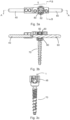
- a connecting device 10 of a first embodiment is shown in Fig. 1a shown in perspective view.
- Fig. 1a On the far right you can see a first fastening arrangement 1 with a spring arm 1a and a hole 11 with a thread (not shown) for screwing in a clamping screw (not shown).
- the first fastening arrangement 1 serves to fasten the connecting device 10 to a connecting rod 60 ( Fig. 3a ) a spinal support.
- the connecting device 10 has a second fastening arrangement 2 in the left end area.
- This has a bore 22 set into the material of the end area, which extends in the longitudinal direction of the connecting device 10, and threaded through-bores 12 running in the vertical direction, which reach up to the bore 22.
- the second fastening arrangement 2 thus serves to fasten a rod 40 which forms part of a support extending the spinal support having the connecting rod 60, although in Fig. 3b only the rod 40 itself is shown.
- An intermediate region 5 between the first fastening arrangement 1 and the second fastening arrangement 2 has a sleeve-like region 4 adjacent to the first fastening arrangement 1, the interior 6 of which is cylindrical in this embodiment, with the cylinder axis extending in the vertical direction.
- the sleeve-like area 4 is connected in one piece with the first fastening arrangement 1.
- a coupling device 80 is accommodated in the interior 6, which couples a pedicle screw 70 of the spinal support with its connecting rod 60 in a fixing manner.
- the first fastening arrangement 1 and the second fastening arrangement 2 are integrally connected to one another via the intermediate region 5.
- a third fastening arrangement 3 with spring arm 3a and threaded bore 13 is arranged, which in this embodiment is identical in construction to the first fastening arrangement 1 and is described below with reference to the Fig. 2
- the third fastening arrangement 3 serves, like the fastening arrangement 1, to fix the connecting device to the connecting rod 60 of an already implanted spinal support, but on the side of the coupling device 80 facing away from the fastening arrangement 1, at the free end of the connecting rod 60.
- the first and third fastening arrangements 1, 3 thus surround the coupling device of the spinal support to be extended in a sandwich-like manner, and the sleeve-like area 4 or its lateral walls 48 nestle against the coupling device 80.
- the first fastening arrangement 1 and the third fastening arrangement 3 are integrally connected to one another via the sleeve-like region 4.
- a receiving groove 16 for the connecting rod 60 in this embodiment runs axially centrally and almost coaxially to the bore 22.
- the mouth opening of the groove 16 is slightly narrower than the diameter of the groove 16 in the unloaded state of the spring arms 1a, 3a.
- the fastening arrangements 1, 3 can thus be clipped onto the connecting rod 60 with elastic yielding of their spring arms 1a, 3a, while During this clipping movement, the sleeve-like region 4 is slipped over the coupling device 80.
- the threaded holes 11 and 13 do not extend to the groove 16 ( Fig. 2 ).
- Fig. 1b and Fig. 2b can be seen, is arranged off-center in relation to the center axis of the connecting device 10 in the direction of the spring arms 1a, 3a, so that when the clamping screws are screwed in, the spring effect of the spring arms 1a, 3a is initially canceled and in this state, the connection device 10 cannot be removed from the spinal support (rod 60).
- the connecting device 10 is rigidly and firmly connected to the connecting rod 60 of the already implanted spinal support.
- the rod 40 of the extension section of this spinal support is thus also rigidly and firmly connected to the spinal support to be extended via the second fastening arrangement 2.
- Fig. 2b As can be seen, the thread for bore 11 and the opposing lateral boundaries of the groove 16 are integrally connected to one another.
- the function of the clip-on capability of the fastening arrangement 1 is implemented in that, as seen in cross section to the channel 16, the boundary of the channel 16 is formed on one side by the inner surface of the resilient arm 1a, on the opposite side by a side structure of the fastening arrangement 1 that takes over the function of the fixed arm 1b, and the two arms 1a and 1b are only connected to one another by a material bridge 1c of small thickness.
- the material and dimensions of the material bridge 1c are coordinated in such a way that the resilient arm 1a is prevented from breaking off in the event of accidental, unintentional force.
- the lateral boundaries 1a, 1b of the channel are opposite one another in a transverse direction or lateral direction that runs orthogonally to the threaded bore 11.
- the threaded bore 11 is not arranged centrally in relation to the lateral boundaries 1a, 1b, but is displaced off-center in the transverse direction towards the spring arm 1a.
- FIG. 3 In addition to the sectional views shown, components that can be seen in projection are also shown, such as the pedicle screw 70 in Fig. 3c or the side areas 48 of the sleeve-like area 4 in order to be able to recognize the position of these parts/objects.
- Fig. 3a It is clearly visible that the side of the connecting device 10 that is coupled to the connecting rod 60 is wrapped like a cuff or bandage around the end region of the already implanted spinal support that has not only the connecting rod 60 but also the coupling device 80.
- the maximum transverse dimension of the connecting device 10, formed here by the transverse distance between the two side walls 48 of the sleeve-shaped region 4, is only about 2.5 times the diameter of the connecting rod 60 or the groove 16 designed to accommodate it.
- the connecting device 10 can simply be snapped onto this end region without requiring any manipulation of the end region on the rod 60 and/or coupling device 80, nor any loosening of the locking screw 82 of the coupling device 80.
- the latter can be designed according to the techniques used in the years, for example in WO 2009/015100 A2 or EP 2 581 057 B1 described, for example with a tulip, a saddle accommodated in the tulip, in which the head of the pedicle screw 70 is accommodated, and the screw 82 exerting clamping pressure on the saddle via the connecting rod 60 for firmly coupling the screw 70, which is designed in particular as a polyaxial screw, in the desired angular position to the connecting rod 60. Similar systems can then also be used for the lengthening spinal support section with the rod 40.
- the upper section of the coupling device 80 can be entirely accommodated in the interior 6 of the sleeve-like region 4. In this way, a comparatively flat surface side of the connecting device can be formed in the deployed state.
- the axes for the rods 40, 60 would not have to be collinear, nor even parallel, if angled connections are required.
- the second fastening arrangement 2 could also be designed differently, for example similar to the first fastening arrangement or with a lateral insertion groove instead of the blind hole 22.
- the sleeve-like fit could also be achieved by clipping it onto the connecting rod 60 from the side, for this the sleeve-like region 4 would have to be modified to suit a lateral attachment.
- one of the side arms 48 of the sleeve-like region 4 can also be sufficient.
- the flange-like end regions of the side walls 48 that project downwards could, for example, be shorter, have incisions, or the structure of the sleeve-like region could be replaced by a ring structure corresponding to its upper region.
- variants are also being considered in which the third fastening arrangement is moved to the side of the first fastening arrangement or the first fastening arrangement alone ensures sufficient coupling to the connecting rod 60.
- the rod of the extension section can also already be a firmly coupled part of the connecting device.
- Fig.4 shown in a schematic representation. It can be seen that in the connecting device 10' shown there, the rod 40' acting to extend the rod 60 is already connected in one piece, for example via a flange 2' of the connecting device 10' adjacent to the third fastening arrangement 3. As can be seen from Fig.4 As can be seen, the flange 2' and the first fastening arrangement 1 are connected to one another in one piece via the intermediate region 5. In this way, several connecting devices 10' with rods 40' of different lengths can be provided, depending on the length dimension of the extension required. The remaining design of the connecting device 10' can be the same as that of the connecting device 10 from Fig.
- the components of the connecting device are made of a biocompatible material, such as stainless steel, titanium or biocompatible polymers, as are known to the person skilled in the art.
- Preparation of the connector assembly for use may include a disinfection step and/or autoclaving step as well as appropriate provision of not only the connector assembly but also the entire extending spine support assembly with appropriate length connector rod 40 (40', 40") and pedicle screws/coupling devices similar to the assembly described in the Fig.3 and 5 shown pedicle screw 70 and coupling device 80, for the specific design of which the usual constructions are open, such as those presented in the documents referred to above.
Landscapes
- Health & Medical Sciences (AREA)
- Orthopedic Medicine & Surgery (AREA)
- Neurology (AREA)
- Life Sciences & Earth Sciences (AREA)
- Engineering & Computer Science (AREA)
- Biomedical Technology (AREA)
- Surgery (AREA)
- General Health & Medical Sciences (AREA)
- Veterinary Medicine (AREA)
- Heart & Thoracic Surgery (AREA)
- Public Health (AREA)
- Animal Behavior & Ethology (AREA)
- Molecular Biology (AREA)
- Medical Informatics (AREA)
- Nuclear Medicine, Radiotherapy & Molecular Imaging (AREA)
- Cardiology (AREA)
- Oral & Maxillofacial Surgery (AREA)
- Transplantation (AREA)
- Vascular Medicine (AREA)
- Surgical Instruments (AREA)
Claims (14)
- Dispositif de raccordement (10 ; 10') servant à raccorder une région terminale d'un premier support rachidien déjà implanté, dans lequel une pluralité de vis pédiculaires (70) sont couplées par leur côté tête à une première tige de raccordement (60) par le biais d'un dispositif de couplage (80) respectif, à une portion de support rachidien qui est déjà implantée ou à implanter, qui comporte une vis pédiculaire et qui prolonge le premier support rachidien, ledit dispositif de raccordement comportant :un premier agencement de fixation (1) permettant une fixation du dispositif de raccordement à la première tige de raccordement (60), etun accouplement pour la portion de support de prolongement, notamment sous la forme d'une deuxième tige (40') à coupler à la vis pédiculaire de la portion de support de prolongement, ou d'un deuxième agencement de fixation (2) permettant une fixation du dispositif de raccordement (10) à une telle deuxième tige (40) ; et comportant en outre :un pontage rigide d'une zone intermédiaire (5) située entre le premier agencement de fixation et l'accouplement, lequel pontage épouse latéralement le dispositif de couplage (80) de la vis pédiculaire (70) du premier support rachidien déjà implanté qui est la plus proche sur le côté raccordement; ledit premier agencement de fixation (1), pour positionner le dispositif de raccordement par rapport au premier support rachidien, pouvant être mis en place radialement sur la région terminale comprenant le dispositif de couplage (80) de la vis pédiculaire la plus proche sur le côté raccordement, grâce à une faculté d'enclipsage fournie par un dispositif élastique du premier agencement de fixation, et le dispositif de raccordement comportant des moyens de serrage pour serrer la première tige de raccordement (60) contre le premier agencement de fixation (1),caractérisé en ce que le dispositif élastique est conçu de telle façon qu'une délimitation latérale d'une zone de réception qui reçoit la première tige de raccordement (60) et qui présente la forme d'une rainure de réception (16) est formée par la surface intérieure d'un bras élastique (1a), et l'autre délimitation latérale, située du côté opposé, est formée par une structure latérale du premier agencement de fixation qui assure la fonction d'un bras fixe,moyennant quoi, lors du vissage d'une vis de serrage qui est vissable dans un alésage (11) fileté ne s'étendant pas jusqu'à déboucher dans la rainure de réception (16) et qui permet de serrer la tige de raccordement (60) grâce à son agencement excentré par rapport à la rainure de réception, une force orientée dans la direction axiale est reçue de manière non centrée eu égard au centre de la tige de raccordement, vu en coupe transversale.
- Dispositif de raccordement selon la revendication 1, dans lequel la faculté du pontage à épouser le dispositif de couplage est bilatérale.
- Dispositif de raccordement selon la revendication 1 ou 2, dans lequel l'étendue en hauteur du pontage ne dépasse pas la hauteur du dispositif de couplage de plus de 100 %, de préférence pas de plus de 60 %, notamment pas de plus de 30 %.
- Dispositif de raccordement selon l'une des revendications précédentes, comportant un troisième agencement de fixation (3) permettant de le fixer à la première tige de raccordement (60) à son extrémité libre côté raccordement.
- Dispositif de raccordement selon l'une des revendications précédentes, dans lequel la possibilité de mise en place sur la région terminale est assurée par le haut.
- Dispositif de raccordement selon la revendication 4 ou 5, dans lequel la possibilité de mise en place comprend une faculté d'enclipsage y compris du troisième agencement de fixation (3) au moyen d'un dispositif élastique (3a).
- Dispositif de raccordement selon l'une des revendications précédentes, comportant une vis de serrage supplémentaire qui est disposée excentrée par rapport à une zone de réception (16) du troisième agencement de fixation qui reçoit la première tige de raccordement (60).
- Dispositif de raccordement selon l'une des revendications précédentes, dans lequel le deuxième agencement de fixation (2) est conçu pour une insertion axiale, dans sa direction longitudinale, de la deuxième tige (40) et est notamment constitué sous la forme d'un alésage axial dans un bloc de matière.
- Dispositif de raccordement selon l'une des revendications précédentes, lequel est conçu pour permettre une position sensiblement colinéaire de la première tige de raccordement (60) et de la deuxième tige (40 ; 40').
- Dispositif de raccordement selon l'une des revendications précédentes, dont la dimension transversale maximale est inférieure à 1/3, de préférence inférieure à 2/7 de sa dimension axiale, calculée en l'absence de deuxième tige (40') éventuelle, et/ou inférieure à 440 %, notamment 360 % du diamètre de la zone de réception (16) destinée à la première tige de raccordement.
- Ensemble de prolongement pour prolonger un premier support rachidien déjà implanté, comportant un dispositif de raccordement (10 ; 10') selon l'une des revendications précédentes et au moins une vis pédiculaire, une deuxième tige (40 ; 40'), celle-ci faisant éventuellement déjà partie du dispositif de raccordement, et au moins un dispositif de couplage pour réaliser un raccordement rigide entre la vis pédiculaire et la deuxième tige (40 ; 40').
- Support rachidien, présentant un premier support rachidien doté d'une pluralité de vis pédiculaires couplées par leur côté tête à une première tige de raccordement (60) par le biais d'un dispositif de couplage (80) respectif, caractérisé par un prolongement raccordé au moyen d'un dispositif de raccordement (10 ; 10') selon une l'une des revendications 1 à 10.
- Préparation d'un ensemble de prolongement selon la revendication 11, réalisé dans un matériau biocompatible, en vue de son utilisation prochaine pour créer un prolongement d'un support rachidien déjà implanté.
- Assortiment comprenant au moins deux et notamment au moins quatre dispositifs de raccordement selon l'une des revendications 1 à 10, dans lequel les premiers agencements de fixation d'au moins deux dispositifs de raccordement sont de conceptions différentes l'un de l'autre, permettant leur fixation sur des tiges de raccordement de dimensions transversales différentes, leur faculté de mise en place sur des dispositifs de couplage de dimensions spatiales différentes, et/ou dans lequel au moins deux dispositifs de raccordement présentent des deuxièmes tiges (40') de longueurs différentes.
Applications Claiming Priority (2)
| Application Number | Priority Date | Filing Date | Title |
|---|---|---|---|
| DE102019005374.5A DE102019005374A1 (de) | 2019-07-30 | 2019-07-30 | Wirbelsäulenimplantatsverbindungseinrichtung |
| PCT/EP2020/071578 WO2021019046A1 (fr) | 2019-07-30 | 2020-07-30 | Dispositif de raccordement d'implant de colonne vertébrale |
Publications (3)
| Publication Number | Publication Date |
|---|---|
| EP4003196A1 EP4003196A1 (fr) | 2022-06-01 |
| EP4003196C0 EP4003196C0 (fr) | 2024-08-28 |
| EP4003196B1 true EP4003196B1 (fr) | 2024-08-28 |
Family
ID=72039570
Family Applications (1)
| Application Number | Title | Priority Date | Filing Date |
|---|---|---|---|
| EP20753902.4A Active EP4003196B1 (fr) | 2019-07-30 | 2020-07-30 | Dispositif de raccordement d'implant de colonne vertébrale |
Country Status (9)
| Country | Link |
|---|---|
| US (1) | US12213705B2 (fr) |
| EP (1) | EP4003196B1 (fr) |
| JP (1) | JP7550841B2 (fr) |
| KR (1) | KR102949422B1 (fr) |
| CN (1) | CN114423386B (fr) |
| AU (1) | AU2020322099B2 (fr) |
| DE (1) | DE102019005374A1 (fr) |
| ES (1) | ES2992257T3 (fr) |
| WO (1) | WO2021019046A1 (fr) |
Families Citing this family (1)
| Publication number | Priority date | Publication date | Assignee | Title |
|---|---|---|---|---|
| US20250120749A1 (en) * | 2023-10-17 | 2025-04-17 | Nexus Spine, LLC | Add-on coupler for medical implant revision |
Family Cites Families (18)
| Publication number | Priority date | Publication date | Assignee | Title |
|---|---|---|---|---|
| US7648520B2 (en) * | 2004-04-16 | 2010-01-19 | Kyphon Sarl | Pedicle screw assembly |
| US8097022B2 (en) | 2007-02-20 | 2012-01-17 | Warsaw Orthopedic, Inc. | Flexible coupling members for spinal stabilization members |
| FR2918555B1 (fr) | 2007-07-12 | 2010-04-02 | Ldr Medical | Dispositif et systeme de liaison rachidienne transverse |
| EP2170192B1 (fr) | 2007-07-20 | 2011-02-09 | Synthes GmbH | Élément de fixation d'os à plusieurs axes |
| US8425564B2 (en) * | 2008-01-03 | 2013-04-23 | P. Douglas Kiester | Spine reconstruction rod extender |
| ES2548580T3 (es) | 2009-02-20 | 2015-10-19 | Biedermann Technologies Gmbh & Co. Kg | Parte receptora para alojar una varilla para el acoplamiento a un elemento de anclaje óseo y dispositivo de anclaje óseo que incluye tal parte receptora |
| EP2408389B1 (fr) * | 2009-02-23 | 2021-04-14 | Crocker Spinal, L.L.C. | Liaison à pression pour des vis chirurgicales |
| US8882803B2 (en) | 2009-04-01 | 2014-11-11 | Globus Medical, Inc. | Orthopedic clamp and extension rod |
| KR20120013312A (ko) * | 2009-04-15 | 2012-02-14 | 신세스 게엠바하 | 척추 구조물용 교정 커넥터 |
| EP2480149B1 (fr) * | 2009-12-10 | 2017-05-03 | Kilian Kraus | Connecteur de tiges de liaison transversale de deux tiges vertébrales |
| US20120109202A1 (en) | 2010-04-30 | 2012-05-03 | Neuraxis Llc | Intersegmental motion preservation system for use in the spine and methods for use thereof |
| US9649136B2 (en) * | 2011-07-15 | 2017-05-16 | Globus Medical, Inc. | Coupling devices and methods of using the same |
| DE202011107821U1 (de) * | 2011-09-09 | 2012-02-23 | Humantech Germany Gmbh | Stabverlängerungssystem zur Erweiterung eines bestehenden Schrauben-Stab Implantats zur Fixation der Wirbelsäule |
| ES2527766T3 (es) | 2012-05-29 | 2015-01-29 | Biedermann Technologies Gmbh & Co. Kg | Pieza receptora para recibir y alojar una barra con el fin de acoplarla con un elemento de anclaje de hueso, y dispositivo de anclaje de hueso con una pieza receptora de este tipo |
| US20140277163A1 (en) | 2013-03-15 | 2014-09-18 | Ryan Kretzer | Reinforcement systems for spine stabilization constructs |
| US10206718B1 (en) * | 2016-02-17 | 2019-02-19 | Seaspine Orthopedics Corporation | Implantable connector |
| US10278735B2 (en) * | 2016-06-02 | 2019-05-07 | Warsaw Orthopedic, Inc. | Percutaneous rod revision implant |
| US10786285B2 (en) * | 2016-06-06 | 2020-09-29 | Stryker European Holdings I, Llc | Paraxial revision rod-to-rod connector |
-
2019
- 2019-07-30 DE DE102019005374.5A patent/DE102019005374A1/de active Pending
-
2020
- 2020-07-30 KR KR1020227005741A patent/KR102949422B1/ko active Active
- 2020-07-30 WO PCT/EP2020/071578 patent/WO2021019046A1/fr not_active Ceased
- 2020-07-30 CN CN202080068227.3A patent/CN114423386B/zh active Active
- 2020-07-30 JP JP2022506679A patent/JP7550841B2/ja active Active
- 2020-07-30 EP EP20753902.4A patent/EP4003196B1/fr active Active
- 2020-07-30 AU AU2020322099A patent/AU2020322099B2/en active Active
- 2020-07-30 ES ES20753902T patent/ES2992257T3/es active Active
- 2020-07-30 US US17/627,369 patent/US12213705B2/en active Active
Also Published As
| Publication number | Publication date |
|---|---|
| DE102019005374A1 (de) | 2021-02-04 |
| AU2020322099B2 (en) | 2025-12-11 |
| EP4003196C0 (fr) | 2024-08-28 |
| WO2021019046A1 (fr) | 2021-02-04 |
| EP4003196A1 (fr) | 2022-06-01 |
| CN114423386B (zh) | 2025-06-10 |
| US12213705B2 (en) | 2025-02-04 |
| ES2992257T3 (es) | 2024-12-10 |
| JP2022542700A (ja) | 2022-10-06 |
| CN114423386A (zh) | 2022-04-29 |
| JP7550841B2 (ja) | 2024-09-13 |
| KR20220042157A (ko) | 2022-04-04 |
| KR102949422B1 (ko) | 2026-04-09 |
| US20220257286A1 (en) | 2022-08-18 |
| AU2020322099A1 (en) | 2022-02-10 |
Similar Documents
| Publication | Publication Date | Title |
|---|---|---|
| DE60032225T2 (de) | Apparat zur stabilisierung der wirbelsäule | |
| EP3117787B1 (fr) | Vis pediculaire avec tulipe | |
| EP2299920B1 (fr) | Dispositif d'ostéosynthèse, de fixation et de stabilisation d'os longs | |
| EP0634912B1 (fr) | Dispositif permettant de raidir et/ou de corriger la colonne vertebrale | |
| EP2114274B1 (fr) | Implant sous forme de plaque, à utilisation destinée notamment à la colonne vertébrale | |
| AT389992B (de) | Vorrichtung zur externen fixierung von knochenfragmenten | |
| EP2996594B1 (fr) | Plaque d'ostéosynthèse et système d'ostéosynthèse | |
| DE69731831T2 (de) | Verschlusskappe für eine pedikelschraube | |
| DE4102462C2 (de) | Stabiliersierelement zur Osteosynthese von Knochenfragmenten, insbesondere zur Fixation von Knochenfrakturen | |
| DE69431361T2 (de) | Transversale verbindung für spinale implantatsysteme | |
| DE69309272T2 (de) | Apparat zur behandlung der wirbelsäule | |
| EP2505154A1 (fr) | Implant de colonne vertébrale | |
| WO2012072733A1 (fr) | Implant pour fusion osseuse destiné aux articulations zygapophysaires | |
| EP2618755B1 (fr) | Système de stabilisation de la colonne vertébrale et dispositif chirurgical de raidissement temporaire d'une partie intermédiaire souple d'un élément de liaison du système de stabilisation de la colonne vertébrale | |
| EP3031416B1 (fr) | Dispositif d'osteosynthese | |
| EP4003196B1 (fr) | Dispositif de raccordement d'implant de colonne vertébrale | |
| EP1935360A1 (fr) | Implant de plaque, en particulier pour l'application sur une colonne vertébrale, doté d'un système de fermeture à vis | |
| EP2436325B1 (fr) | Implant de colonne vertébrale pour la stabilisation et le raidissement de vertèbres | |
| EP1364621B1 (fr) | Dispositif pour la mise en place et fixation des os et/ou des fragments d'os | |
| DE4414782C2 (de) | Knochenchirurgische Haltevorrichtung | |
| EP3988049B1 (fr) | Dispositif distracteur | |
| EP3554402B1 (fr) | Implant pour ostéosynthèse et kit de montage d'implant avec implant | |
| DE9310668U1 (de) | Schraubendreher | |
| WO2012007308A1 (fr) | Implant vertébral comportant des vis pédiculaires et vis pédiculaire correspondante | |
| EP4003197B1 (fr) | Implant, notamment implant vertébral |
Legal Events
| Date | Code | Title | Description |
|---|---|---|---|
| STAA | Information on the status of an ep patent application or granted ep patent |
Free format text: STATUS: UNKNOWN |
|
| STAA | Information on the status of an ep patent application or granted ep patent |
Free format text: STATUS: THE INTERNATIONAL PUBLICATION HAS BEEN MADE |
|
| PUAI | Public reference made under article 153(3) epc to a published international application that has entered the european phase |
Free format text: ORIGINAL CODE: 0009012 |
|
| STAA | Information on the status of an ep patent application or granted ep patent |
Free format text: STATUS: REQUEST FOR EXAMINATION WAS MADE |
|
| 17P | Request for examination filed |
Effective date: 20211217 |
|
| AK | Designated contracting states |
Kind code of ref document: A1 Designated state(s): AL AT BE BG CH CY CZ DE DK EE ES FI FR GB GR HR HU IE IS IT LI LT LU LV MC MK MT NL NO PL PT RO RS SE SI SK SM TR |
|
| DAV | Request for validation of the european patent (deleted) | ||
| DAX | Request for extension of the european patent (deleted) | ||
| GRAP | Despatch of communication of intention to grant a patent |
Free format text: ORIGINAL CODE: EPIDOSNIGR1 |
|
| STAA | Information on the status of an ep patent application or granted ep patent |
Free format text: STATUS: GRANT OF PATENT IS INTENDED |
|
| INTG | Intention to grant announced |
Effective date: 20240322 |
|
| GRAS | Grant fee paid |
Free format text: ORIGINAL CODE: EPIDOSNIGR3 |
|
| GRAA | (expected) grant |
Free format text: ORIGINAL CODE: 0009210 |
|
| STAA | Information on the status of an ep patent application or granted ep patent |
Free format text: STATUS: THE PATENT HAS BEEN GRANTED |
|
| AK | Designated contracting states |
Kind code of ref document: B1 Designated state(s): AL AT BE BG CH CY CZ DE DK EE ES FI FR GB GR HR HU IE IS IT LI LT LU LV MC MK MT NL NO PL PT RO RS SE SI SK SM TR |
|
| REG | Reference to a national code |
Ref country code: CH Ref legal event code: EP |
|
| REG | Reference to a national code |
Ref country code: DE Ref legal event code: R096 Ref document number: 502020009047 Country of ref document: DE |
|
| REG | Reference to a national code |
Ref country code: IE Ref legal event code: FG4D Free format text: LANGUAGE OF EP DOCUMENT: GERMAN |
|
| U01 | Request for unitary effect filed |
Effective date: 20240920 |
|
| U07 | Unitary effect registered |
Designated state(s): AT BE BG DE DK EE FI FR IT LT LU LV MT NL PT RO SE SI Effective date: 20241014 |
|
| REG | Reference to a national code |
Ref country code: ES Ref legal event code: FG2A Ref document number: 2992257 Country of ref document: ES Kind code of ref document: T3 Effective date: 20241210 |
|
| PG25 | Lapsed in a contracting state [announced via postgrant information from national office to epo] |
Ref country code: NO Free format text: LAPSE BECAUSE OF FAILURE TO SUBMIT A TRANSLATION OF THE DESCRIPTION OR TO PAY THE FEE WITHIN THE PRESCRIBED TIME-LIMIT Effective date: 20241128 |
|
| PG25 | Lapsed in a contracting state [announced via postgrant information from national office to epo] |
Ref country code: PL Free format text: LAPSE BECAUSE OF FAILURE TO SUBMIT A TRANSLATION OF THE DESCRIPTION OR TO PAY THE FEE WITHIN THE PRESCRIBED TIME-LIMIT Effective date: 20240828 Ref country code: GR Free format text: LAPSE BECAUSE OF FAILURE TO SUBMIT A TRANSLATION OF THE DESCRIPTION OR TO PAY THE FEE WITHIN THE PRESCRIBED TIME-LIMIT Effective date: 20241129 |
|
| PG25 | Lapsed in a contracting state [announced via postgrant information from national office to epo] |
Ref country code: IS Free format text: LAPSE BECAUSE OF FAILURE TO SUBMIT A TRANSLATION OF THE DESCRIPTION OR TO PAY THE FEE WITHIN THE PRESCRIBED TIME-LIMIT Effective date: 20241228 |
|
| PG25 | Lapsed in a contracting state [announced via postgrant information from national office to epo] |
Ref country code: HR Free format text: LAPSE BECAUSE OF FAILURE TO SUBMIT A TRANSLATION OF THE DESCRIPTION OR TO PAY THE FEE WITHIN THE PRESCRIBED TIME-LIMIT Effective date: 20240828 |
|
| PG25 | Lapsed in a contracting state [announced via postgrant information from national office to epo] |
Ref country code: RS Free format text: LAPSE BECAUSE OF FAILURE TO SUBMIT A TRANSLATION OF THE DESCRIPTION OR TO PAY THE FEE WITHIN THE PRESCRIBED TIME-LIMIT Effective date: 20241128 |
|
| PG25 | Lapsed in a contracting state [announced via postgrant information from national office to epo] |
Ref country code: RS Free format text: LAPSE BECAUSE OF FAILURE TO SUBMIT A TRANSLATION OF THE DESCRIPTION OR TO PAY THE FEE WITHIN THE PRESCRIBED TIME-LIMIT Effective date: 20241128 Ref country code: PL Free format text: LAPSE BECAUSE OF FAILURE TO SUBMIT A TRANSLATION OF THE DESCRIPTION OR TO PAY THE FEE WITHIN THE PRESCRIBED TIME-LIMIT Effective date: 20240828 Ref country code: NO Free format text: LAPSE BECAUSE OF FAILURE TO SUBMIT A TRANSLATION OF THE DESCRIPTION OR TO PAY THE FEE WITHIN THE PRESCRIBED TIME-LIMIT Effective date: 20241128 Ref country code: IS Free format text: LAPSE BECAUSE OF FAILURE TO SUBMIT A TRANSLATION OF THE DESCRIPTION OR TO PAY THE FEE WITHIN THE PRESCRIBED TIME-LIMIT Effective date: 20241228 Ref country code: HR Free format text: LAPSE BECAUSE OF FAILURE TO SUBMIT A TRANSLATION OF THE DESCRIPTION OR TO PAY THE FEE WITHIN THE PRESCRIBED TIME-LIMIT Effective date: 20240828 Ref country code: GR Free format text: LAPSE BECAUSE OF FAILURE TO SUBMIT A TRANSLATION OF THE DESCRIPTION OR TO PAY THE FEE WITHIN THE PRESCRIBED TIME-LIMIT Effective date: 20241129 |
|
| PG25 | Lapsed in a contracting state [announced via postgrant information from national office to epo] |
Ref country code: SM Free format text: LAPSE BECAUSE OF FAILURE TO SUBMIT A TRANSLATION OF THE DESCRIPTION OR TO PAY THE FEE WITHIN THE PRESCRIBED TIME-LIMIT Effective date: 20240828 |
|
| PG25 | Lapsed in a contracting state [announced via postgrant information from national office to epo] |
Ref country code: CZ Free format text: LAPSE BECAUSE OF FAILURE TO SUBMIT A TRANSLATION OF THE DESCRIPTION OR TO PAY THE FEE WITHIN THE PRESCRIBED TIME-LIMIT Effective date: 20240828 |
|
| PG25 | Lapsed in a contracting state [announced via postgrant information from national office to epo] |
Ref country code: SK Free format text: LAPSE BECAUSE OF FAILURE TO SUBMIT A TRANSLATION OF THE DESCRIPTION OR TO PAY THE FEE WITHIN THE PRESCRIBED TIME-LIMIT Effective date: 20240828 |
|
| PLBE | No opposition filed within time limit |
Free format text: ORIGINAL CODE: 0009261 |
|
| STAA | Information on the status of an ep patent application or granted ep patent |
Free format text: STATUS: NO OPPOSITION FILED WITHIN TIME LIMIT |
|
| 26N | No opposition filed |
Effective date: 20250530 |
|
| U20 | Renewal fee for the european patent with unitary effect paid |
Year of fee payment: 6 Effective date: 20250717 |
|
| PGFP | Annual fee paid to national office [announced via postgrant information from national office to epo] |
Ref country code: ES Payment date: 20250801 Year of fee payment: 6 |
|
| PGFP | Annual fee paid to national office [announced via postgrant information from national office to epo] |
Ref country code: GB Payment date: 20250721 Year of fee payment: 6 |
|
| REG | Reference to a national code |
Ref country code: CH Ref legal event code: U11 Free format text: ST27 STATUS EVENT CODE: U-0-0-U10-U11 (AS PROVIDED BY THE NATIONAL OFFICE) Effective date: 20251022 |
|
| PGFP | Annual fee paid to national office [announced via postgrant information from national office to epo] |
Ref country code: CH Payment date: 20251022 Year of fee payment: 6 |