EP4003640B1 - Plateforme pour transporter des pièces de travail dans une chaîne d'assemblage et procédé pour placer des pièces de travail sur celle-ci - Google Patents
Plateforme pour transporter des pièces de travail dans une chaîne d'assemblage et procédé pour placer des pièces de travail sur celle-ci Download PDFInfo
- Publication number
- EP4003640B1 EP4003640B1 EP19758611.8A EP19758611A EP4003640B1 EP 4003640 B1 EP4003640 B1 EP 4003640B1 EP 19758611 A EP19758611 A EP 19758611A EP 4003640 B1 EP4003640 B1 EP 4003640B1
- Authority
- EP
- European Patent Office
- Prior art keywords
- platform
- plane
- inclined surface
- elements
- work part
- Prior art date
- Legal status (The legal status is an assumption and is not a legal conclusion. Google has not performed a legal analysis and makes no representation as to the accuracy of the status listed.)
- Active
Links
Images


Classifications
-
- B—PERFORMING OPERATIONS; TRANSPORTING
- B23—MACHINE TOOLS; METAL-WORKING NOT OTHERWISE PROVIDED FOR
- B23P—METAL-WORKING NOT OTHERWISE PROVIDED FOR; COMBINED OPERATIONS; UNIVERSAL MACHINE TOOLS
- B23P21/00—Machines for assembling a multiplicity of different parts to compose units, with or without preceding or subsequent working of such parts, e.g. with program control
- B23P21/004—Machines for assembling a multiplicity of different parts to compose units, with or without preceding or subsequent working of such parts, e.g. with program control the units passing two or more work-stations whilst being composed
-
- B—PERFORMING OPERATIONS; TRANSPORTING
- B25—HAND TOOLS; PORTABLE POWER-DRIVEN TOOLS; MANIPULATORS
- B25H—WORKSHOP EQUIPMENT, e.g. FOR MARKING-OUT WORK; STORAGE MEANS FOR WORKSHOPS
- B25H1/00—Work benches; Portable stands or supports for positioning portable tools or work to be operated on thereby
- B25H1/14—Work benches; Portable stands or supports for positioning portable tools or work to be operated on thereby with provision for adjusting the bench top
- B25H1/18—Work benches; Portable stands or supports for positioning portable tools or work to be operated on thereby with provision for adjusting the bench top in inclination
-
- B—PERFORMING OPERATIONS; TRANSPORTING
- B25—HAND TOOLS; PORTABLE POWER-DRIVEN TOOLS; MANIPULATORS
- B25B—TOOLS OR BENCH DEVICES NOT OTHERWISE PROVIDED FOR, FOR FASTENING, CONNECTING, DISENGAGING, OR HOLDING
- B25B11/00—Work holders not covered by any preceding group in the subclass, e.g. magnetic work holders, vacuum work holders
-
- B—PERFORMING OPERATIONS; TRANSPORTING
- B62—LAND VEHICLES FOR TRAVELLING OTHERWISE THAN ON RAILS
- B62D—MOTOR VEHICLES; TRAILERS
- B62D65/00—Designing, manufacturing, e.g. assembling, facilitating disassembly, or structurally modifying motor vehicles or trailers, not otherwise provided for
- B62D65/02—Joining sub-units or components to, or positioning sub-units or components with respect to, body shell or other sub-units or components
- B62D65/022—Transferring or handling sub-units or components, e.g. in work stations or between workstations and transportation systems
-
- B—PERFORMING OPERATIONS; TRANSPORTING
- B62—LAND VEHICLES FOR TRAVELLING OTHERWISE THAN ON RAILS
- B62D—MOTOR VEHICLES; TRAILERS
- B62D65/00—Designing, manufacturing, e.g. assembling, facilitating disassembly, or structurally modifying motor vehicles or trailers, not otherwise provided for
- B62D65/02—Joining sub-units or components to, or positioning sub-units or components with respect to, body shell or other sub-units or components
- B62D65/18—Transportation, conveyor or haulage systems specially adapted for motor vehicle or trailer assembly lines
-
- B—PERFORMING OPERATIONS; TRANSPORTING
- B23—MACHINE TOOLS; METAL-WORKING NOT OTHERWISE PROVIDED FOR
- B23P—METAL-WORKING NOT OTHERWISE PROVIDED FOR; COMBINED OPERATIONS; UNIVERSAL MACHINE TOOLS
- B23P2700/00—Indexing scheme relating to the articles being treated, e.g. manufactured, repaired, assembled, connected or other operations covered in the subgroups
- B23P2700/50—Other automobile vehicle parts, i.e. manufactured in assembly lines
-
- G—PHYSICS
- G05—CONTROLLING; REGULATING
- G05B—CONTROL OR REGULATING SYSTEMS IN GENERAL; FUNCTIONAL ELEMENTS OF SUCH SYSTEMS; MONITORING OR TESTING ARRANGEMENTS FOR SUCH SYSTEMS OR ELEMENTS
- G05B19/00—Program-control systems
- G05B19/02—Program-control systems electric
- G05B19/418—Total factory control, i.e. centrally controlling a plurality of machines, e.g. direct or distributed numerical control [DNC], flexible manufacturing systems [FMS], integrated manufacturing systems [IMS] or computer integrated manufacturing [CIM]
- G05B19/4189—Total factory control, i.e. centrally controlling a plurality of machines, e.g. direct or distributed numerical control [DNC], flexible manufacturing systems [FMS], integrated manufacturing systems [IMS] or computer integrated manufacturing [CIM] characterised by the transport system
- G05B19/41895—Total factory control, i.e. centrally controlling a plurality of machines, e.g. direct or distributed numerical control [DNC], flexible manufacturing systems [FMS], integrated manufacturing systems [IMS] or computer integrated manufacturing [CIM] characterised by the transport system using automatic guided vehicles [AGV]
-
- Y—GENERAL TAGGING OF NEW TECHNOLOGICAL DEVELOPMENTS; GENERAL TAGGING OF CROSS-SECTIONAL TECHNOLOGIES SPANNING OVER SEVERAL SECTIONS OF THE IPC; TECHNICAL SUBJECTS COVERED BY FORMER USPC CROSS-REFERENCE ART COLLECTIONS [XRACs] AND DIGESTS
- Y02—TECHNOLOGIES OR APPLICATIONS FOR MITIGATION OR ADAPTATION AGAINST CLIMATE CHANGE
- Y02P—CLIMATE CHANGE MITIGATION TECHNOLOGIES IN THE PRODUCTION OR PROCESSING OF GOODS
- Y02P90/00—Enabling technologies with a potential contribution to greenhouse gas [GHG] emissions mitigation
- Y02P90/02—Total factory control, e.g. smart factories, flexible manufacturing systems [FMS] or integrated manufacturing systems [IMS]
Definitions
- This invention relates to the field of industrial manufacturing, more specifically to a flexible mobile platform configured to host a plurality of work parts with different shapes.
- a platform as per the preamble of claim 1 is know from document US 2019/129371 A1 . It is known in automotive industry, as described in document WO19020199 , to use a unique mobile platform to convey a complete set of automotive work parts from a workstation to another workstation within an assembly line comprising several workstations, wherein different work parts are successively assembled together, and wherein the assembly could be put back on the platform among other work parts, until a final or an intermediate assembly is produced at the end of the assembly line process.
- the first step of such a process is a configuration step, wherein the mobile platform is prepared before it is loaded with the set of work parts.
- the configuration step consists in providing specific supports elements on the platform, each of these specific supports elements being dedicated to support specific work parts to be loaded on the platform.
- each new automotive model could require a different and specific platform configuration process, based on the specific work parts involved in the assembly of the new automotive model. Therefore, the specificity of the different supports elements which are installed on the platform during the configuration step makes it a complicated and costly step.
- the present invention provides a platform for conveying a plurality of work parts in a sequence of manufacturing stations, the platform being mobile and comprising an inclined surface, and a set of two elements, each element of the two elements being attached to the inclined surface, one element of the set extending along a first plane and another element of the set extending along a second plane, the first plane and the second plane crossing the inclined surface, an intersection of the first plane with the inclined surface defining a first direction, the first direction being oriented upwards with respect to a slope of the inclined surface, an intersection of the second plane with the inclined surface defining a second direction, the second direction being oriented upwards with respect to the slope of the inclined surface, the first direction and the second direction delimiting an angular sector, so that a work part placed on the inclined surface within the angular sector is driven by its weight downwards with respect to the slope of the inclined plane towards an intersection of the first direction and the second direction.
- Preferred embodiments of the invention are provided by the dependent claims. According to these provisions, different work parts repeatedly dropped on the
- the angle formed inside the angular sector is greater than 0 degree, and less than 180 degrees; preferably comprised between 20 degrees and 160 degrees; more preferably comprised between 60 degrees and 120 degrees; even more preferably comprised between 80 degrees and 100 degrees.
- a vertical plane intersects the inclined surface along a third direction oriented upwards with respect to the inclination of the inclined surface, the third direction being within the angular sector.
- a first oriented angle between the third direction and the first direction and a second oriented angle between the third direction and the second direction, are of opposite signs with respect to an angular orientation.
- the work part is more efficiently driven by its weight downwards, towards the intersection of the first direction and the second direction.
- the first direction is forming with the third direction a first angle and the second direction is forming with the third direction a second angle, at least one of or both of the first angle absolute value and the second angle absolute being strictly less than 90 degrees, preferably less than 60 degrees.
- the set of at least two elements constitutes a generic set of supporting elements, adapted to accommodate for the positioning of work parts with a great variety of shapes.
- the work part will be resting stable on the inclined surface and against the first extension plane of one element of the set and against the second extension plane of another element at the set of at least two elements, whatever the shape of the work part.
- the platform configuration does not need to be changed when a new model, with new work parts, is assembled.
- this generic set of at least two elements can accommodate for a positioning of the work parts, which does not need to be very accurate, since it is configured so that by the effect of gravity the work part will be driven to the bottom of the hollow of the angular sector, even if its placement inside the angular sector is not precisely determined.
- the platform comprises at least two inclined surfaces, and at least two sets of two elements, each element of at least one set being attached to one of the at least two inclined surfaces and each element of at least another set being attached to another of the at least two inclined surfaces.
- the inclined plane and/or each element of the set of two elements is (are) configured to enhance the sliding of a work part downwards along the inclined plane and/or along each element, when said work part is placed on the inclined plane.
- the inclined plane and/or each element of the set of two element have a smooth surface with which the work parts are in contact when the work parts are placed on the inclined plane.
- the inclined plane and/or each element of the set of two elements is (are) coated with a material having a coefficient of friction which is function of an inclination of the inclined plane and of another material composing the work parts.
- the inclined plane and/or each element of the set of two elements comprise rolling rollers or rolling balls.
- the platform is subjected to vibrations which enhance sliding of a work part downwards along the inclined plane and/or along each element of the set of two elements, when said work part is placed on the inclined plane.
- the vibrations are generated by the displacement of the platform on a rough surface, preferably on pavement.
- the platform is autoguided.
- the sequence of manufacturing stations is an automotive manufacturing assembly line.
- the invention provides a method for positioning work parts on a platform according to anyone of the preceding claims, the method comprising the following steps:
- the platform 1 is configured to convey work parts 3 to be assembled at different workstations of an assembly line.
- the platform 1 may be a mobile, preferably autoguided, platform.
- the work parts 3 being conveyed on the platform are each positioned on the platform so as to be maintained on the platform at a given position.
- the platform comprises at least one inclined plane 2, 2', the work parts being positioned on one of the inclined planes.
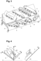
- each of the inclined planes 2, 2' are fixed different sets of two elements; on figure 3 , one such set of two elements is represented, comprising two elements 4, 4; a second such set comprising two elements 5, 5', and a third set comprising two elements 6, 6', are also represented.
- Each element of these sets is protruding transversally from the inclined plane, in such a way that each element is an obstacle for an object sliding downwards along the inclined plane 2, 2'.
- An element 6 of a set of at least two elements 6, 6' is extending along a first plane of extension, said first plane of extension being transverse to the inclined plane, so that the first plane of extension and the inclined plane intersect along a first direction D1, as illustrated on figures 4 and 5 .
- the first direction D1 is oriented in an upward direction with respect to the slope of the inclined plane, as indicated on figures 4 and 5 , where a horizontal direction H on the inclined plane 2, 2' is represented, as well as an upward direction D3 of steepest slope.
- the direction D3 can be defined as the intersection of a vertical plane, i.e. a plane transverse to the horizontal direction H, with the inclined plane 2, 2'.
- An oriented angle A1 is defined between direction D3 and direction D2.
- Another element 6' of the same set of at least two elements 6, 6' is extending along a second plane of extension, said second plane of extension intersecting the inclined plane along a second direction D2, as illustrated on figures 4 and 5 .
- the second direction D2 is oriented in an upward direction with respect to the slope of the inclined plane, so that an oriented angle A2 is defined between direction D3 and direction D2, and an angular sector S is formed between D1 and D2.
- the direction D3 of steepest slope is within the angular sector S, i.e. oriented angle A1 and oriented angle A2 are of opposite signs with respect to a given angular orientation.
- angle A1 absolute value and angle A2 absolute value are strictly less than 90 degrees.
- one or both of angle A1 absolute value and angle A2 absolute value is less than 60 degrees.
- the inclined plane and/or each element of the set of two elements is (are) configured to enhance the sliding of an object downwards along the inclined plane and/or along each element, said object being placed on the inclined plane.
- the surface of the inclined plane 2, 2' and/or of the elements of the sets of elements 4, 4',5, 5', 6, 6' attached to the inclined plane 2, 2' may be coated with some material having a coefficient of friction, the coefficient of friction being function of the inclination of the inclined plane, and of the material composing the work parts; or the surface of the inclined plane 2, 2' and/or of the elements of the sets of elements 4, 4', 5, 5', 6, 6' attached to the inclined plane 2, 2' may comprise rolling rollers or rolling balls.
- the platform is subjected to vibrations which enhance sliding of an object downwards along the inclined plane 2, 2' and/or along each element of the sets of two elements 4, 4', 5, 5', 6, 6', said object being placed on the inclined plane.
- the vibrations may be generated by the displacement of the platform on a rough surface, such as pavement for example.
- the invention concerns a method of positioning work parts 3 on a platform 1, the method comprising the following steps :
Landscapes
- Engineering & Computer Science (AREA)
- Mechanical Engineering (AREA)
- Manufacturing & Machinery (AREA)
- Chemical & Material Sciences (AREA)
- Combustion & Propulsion (AREA)
- Transportation (AREA)
- Automatic Assembly (AREA)
Claims (8)
- Plate-forme (1) de transport d'une pluralité de pièces de travail (3) dans une séquence de postes de fabrication, la plate-forme (1) étant mobile et comprenant une surface inclinée (2, 2') et un ensemble de deux éléments {(4, 4'), (5, 5'), (6, 6')}, chaque élément des deux éléments étant fixé à la surface inclinée,
caractérisée en ce qu'un élément (4, 5, 6) de l'ensemble {(4, 4'), (5, 5'), (6, 6')} s'étend le long d'un premier plan et qu'un autre élément (4', 5', 6') de l'ensemble s'étend le long d'un deuxième plan, le premier plan et le deuxième plan traversent la surface inclinée, une intersection du premier plan avec la surface inclinée définit une première direction (D1), la première direction (D1) étant orientée vers le haut par rapport à une pente de la surface inclinée, une intersection du deuxième plan avec la surface inclinée définit une deuxième direction (D2), la deuxième direction (D2) étant orientée vers le haut par rapport à la pente de la surface inclinée, la première direction (D1) et la deuxième direction (D2) délimitent un secteur angulaire (S), de sorte qu'une pièce de travail placée sur la surface inclinée à l'intérieur du secteur angulaire (S) soit entraînée par son poids vers le bas par rapport à la pente de la surface inclinée vers une intersection de la première direction (D1) et de la deuxième direction (D2). - Plate-forme (1) selon la revendication 1, dans laquelle un plan vertical coupe la surface inclinée (2, 2') le long d'une troisième direction (D3) orientée vers le haut par rapport à l'inclinaison de la surface inclinée (2, 2'), la troisième direction (D3) étant à l'intérieur du secteur angulaire (S).
- Plate-forme (1) selon la revendication une ou deux, dans laquelle la plate-forme comprend au moins deux surfaces inclinées (2, 2'), et au moins deux ensembles de deux éléments {(4, 4'), (5, 5'), (6, 6')}, chaque élément d'au moins un ensemble étant fixé à l'une des au moins deux surfaces inclinées (2, 2') et chaque élément d'au moins un autre ensemble étant fixé à une autre surface des au moins deux surfaces inclinées (2, 2').
- Plate-forme (1) selon l'une quelconque des revendications précédentes, dans laquelle le plan incliné et/ou chaque élément de l'ensemble de deux éléments est (sont) configuré(s) pour favoriser le glissement d'une pièce de travail vers le bas le long du plan incliné et/ou le long de chaque élément, lorsque ladite pièce de travail est placée sur le plan incliné.
- Plate-forme (1) selon l'une quelconque des revendications précédentes, dans laquelle la plate-forme est soumise à des vibrations favorisant le glissement d'une pièce de travail vers le bas le long du plan incliné et/ou le long de chaque élément de l'ensemble de deux éléments, lorsque ladite pièce de travail est placée sur le plan incliné.
- Plate-forme (1) selon l'une quelconque des revendications précédentes, dans laquelle la plate-forme est autoguidée.
- Plate-forme (1) selon l'une quelconque des revendications précédentes, dans laquelle la séquence de postes de fabrication est une chaîne de montage pour la fabrication automobile.
- Procédé (100) de positionnement de pièces de travail sur une plate-forme selon l'une quelconque des revendications précédentes, le procédé (100) comprenant les étapes suivantes de :- saisie (101) d'une pièce de travail à partir d'un lieu de stockage ;- placement (102) de la pièce de travail sur la surface inclinée (2, 2') à l'intérieur du secteur angulaire (S), de sorte que la pièce de travail soit entraînée par son poids vers le bas par rapport à la pente de la surface inclinée vers une intersection de la première direction (D1) et de la deuxième direction (D2) ;- dans un poste de fabrication, saisie (103) de la pièce de travail à partir de la plate-forme dans une position connue répétable déterminée par la surface inclinée et la première direction (D1) et la deuxième direction (D2).
Applications Claiming Priority (1)
| Application Number | Priority Date | Filing Date | Title |
|---|---|---|---|
| PCT/EP2019/070305 WO2021018373A1 (fr) | 2019-07-29 | 2019-07-29 | Plateforme pour transporter des pièces de travail dans une chaîne d'assemblage et procédé pour placer des pièces de travail sur celle-ci |
Publications (2)
| Publication Number | Publication Date |
|---|---|
| EP4003640A1 EP4003640A1 (fr) | 2022-06-01 |
| EP4003640B1 true EP4003640B1 (fr) | 2023-08-30 |
Family
ID=67742347
Family Applications (1)
| Application Number | Title | Priority Date | Filing Date |
|---|---|---|---|
| EP19758611.8A Active EP4003640B1 (fr) | 2019-07-29 | 2019-07-29 | Plateforme pour transporter des pièces de travail dans une chaîne d'assemblage et procédé pour placer des pièces de travail sur celle-ci |
Country Status (5)
| Country | Link |
|---|---|
| US (1) | US12059761B2 (fr) |
| EP (1) | EP4003640B1 (fr) |
| CN (1) | CN114173986A (fr) |
| ES (1) | ES2964294T3 (fr) |
| WO (1) | WO2021018373A1 (fr) |
Families Citing this family (1)
| Publication number | Priority date | Publication date | Assignee | Title |
|---|---|---|---|---|
| DE102021123009A1 (de) | 2021-09-06 | 2023-03-09 | Dr. Ing. H.C. F. Porsche Aktiengesellschaft | Flurförderwagen zum Transport von Fahrzeugteilen |
Family Cites Families (30)
| Publication number | Priority date | Publication date | Assignee | Title |
|---|---|---|---|---|
| US2504947A (en) * | 1947-06-13 | 1950-04-18 | American Steel & Wire Co | Wire bundling stand |
| US3622145A (en) * | 1968-04-19 | 1971-11-23 | Edwin W Glbson | Work-positioning member |
| BE795812A (fr) | 1972-02-22 | 1973-06-18 | Babcock & Wilcox Ltd | Perfectionnements aux appareils de manutention |
| JPH0631036B2 (ja) | 1985-11-07 | 1994-04-27 | 日産自動車株式会社 | 自動車の組立装置 |
| FR2656856A1 (fr) | 1990-01-05 | 1991-07-12 | Laurens Michel | Dispositif de stockage-destockage automatique et dynamique de volumes dans un espace tridimensionnel. |
| US6269938B1 (en) * | 1998-07-08 | 2001-08-07 | David W. Lutz | Over/under line feed system |
| JP2000025911A (ja) | 1998-07-10 | 2000-01-25 | Araco Corp | 搬送装置 |
| WO2004012798A1 (fr) * | 2002-08-05 | 2004-02-12 | Integrated Biosystems, Inc. | Systemes et procedes de degel, melange et traitement de matieres biopharmaceutiques |
| US20080000068A1 (en) * | 2006-06-28 | 2008-01-03 | Savoy Mark A | Adjustment of work pallets for vehicle body assembly lines |
| JP5311010B2 (ja) | 2008-09-01 | 2013-10-09 | トヨタ自動車株式会社 | 積込装置 |
| DE102010049281B4 (de) * | 2010-10-22 | 2014-05-08 | Beumer Gmbh & Co. Kg | Schwerkraftrutsche |
| WO2013083145A1 (fr) | 2011-12-09 | 2013-06-13 | Daimler Ag | Procédé pour faire fonctionner une installation de production |
| CN102642130B (zh) | 2012-05-10 | 2013-12-18 | 黄山科能汽车散热器有限公司 | 一种基于散热管的定位机构 |
| CN203064779U (zh) | 2012-12-28 | 2013-07-17 | 济南吉利汽车有限公司 | 一种焊装主线物料输送装置 |
| US9656364B2 (en) * | 2013-07-16 | 2017-05-23 | Honda Motor Co., Ltd. | Method and fixture for attaching a sanding disc to a hand sander |
| CN203484558U (zh) * | 2013-10-18 | 2014-03-19 | 安徽江淮汽车股份有限公司 | 一种重力对中台的接近开关调整装置 |
| CN103769488B (zh) * | 2014-01-09 | 2015-12-23 | 安徽江淮汽车股份有限公司 | 一种柔性重力对中台 |
| JP2015140209A (ja) | 2014-01-29 | 2015-08-03 | 大日本印刷株式会社 | 梱包台 |
| US9481520B2 (en) * | 2014-07-11 | 2016-11-01 | Abtec Inc. | Disposable chute trays |
| CN205415310U (zh) * | 2016-03-24 | 2016-08-03 | 浙江嘉丰机电有限公司 | 机器人打磨工件自动定位台 |
| CN107150888A (zh) | 2017-06-27 | 2017-09-12 | 潘延庆 | 一种新型自动导引运输装置 |
| WO2019020199A2 (fr) | 2017-07-28 | 2019-01-31 | Abb Schweiz Ag | Procédé d'assemblage robotisé |
| US11084660B2 (en) | 2017-10-27 | 2021-08-10 | Berkshire Grey, Inc. | Bin infeed and removal systems and methods for processing objects including mobile matrix carrier systems |
| CN207709591U (zh) * | 2017-11-29 | 2018-08-10 | 深圳国创名厨商用设备制造有限公司南海分公司 | 一种工件自动折弯生产线 |
| CN108246840A (zh) * | 2017-11-29 | 2018-07-06 | 深圳国创名厨商用设备制造有限公司南海分公司 | 一种工件自动折弯生产线 |
| CN207932427U (zh) | 2018-01-15 | 2018-10-02 | 广东天图物流股份有限公司 | 一种物流搬运设备 |
| CN109201910A (zh) * | 2018-04-27 | 2019-01-15 | 上海发那科机器人有限公司 | 一种支持多类型板料冲压的重力对中装置 |
| CN208483055U (zh) * | 2018-05-29 | 2019-02-12 | 湖北瑞尔多智能激光装备有限责任公司 | 一种全自动折弯系统 |
| CN209021926U (zh) | 2018-09-25 | 2019-06-25 | 广东远见精密五金有限公司 | 高度和角度可调的矫正夹具 |
| CN208840377U (zh) * | 2018-09-29 | 2019-05-10 | 福建奥瑞斯机器人工程技术有限公司 | 一种钣金加工精定位装置 |
-
2019
- 2019-07-29 WO PCT/EP2019/070305 patent/WO2021018373A1/fr not_active Ceased
- 2019-07-29 CN CN201980098905.8A patent/CN114173986A/zh active Pending
- 2019-07-29 EP EP19758611.8A patent/EP4003640B1/fr active Active
- 2019-07-29 US US17/631,241 patent/US12059761B2/en active Active
- 2019-07-29 ES ES19758611T patent/ES2964294T3/es active Active
Also Published As
| Publication number | Publication date |
|---|---|
| WO2021018373A1 (fr) | 2021-02-04 |
| ES2964294T3 (es) | 2024-04-05 |
| US20220266401A1 (en) | 2022-08-25 |
| EP4003640A1 (fr) | 2022-06-01 |
| US12059761B2 (en) | 2024-08-13 |
| CN114173986A (zh) | 2022-03-11 |
Similar Documents
| Publication | Publication Date | Title |
|---|---|---|
| US10414596B2 (en) | Transport system | |
| CA2281175C (fr) | Decoupage d'ouverture pour toit ouvrant dans un panneau de toit de vehicule | |
| KR101830921B1 (ko) | Pcb기판 운반장치 및 그 방법 | |
| US12059761B2 (en) | Platform for conveying work parts in an assembly line, and method for placing work parts on the same | |
| ES2901694T3 (es) | Procedimiento para la conformación de una pieza de trabajo en forma de plancha | |
| US2739009A (en) | Clamps with pre-stressed and pre-set flexible grab arms | |
| CN105522501B (zh) | 汽车模具泡沫模型装夹夹具 | |
| US12054307B2 (en) | Support tool and carrying tool | |
| JP2023015435A (ja) | 支持具および運搬具 | |
| EP2093795A1 (fr) | Plate-forme suspendue pour pont roulant | |
| CN217577368U (zh) | 一种玻璃顶升夹持装置及玻璃制造系统 | |
| CN211866413U (zh) | 一种折弯工件的翻面装置 | |
| CN218611363U (zh) | 一种连杆整形自动化输送装置 | |
| CN211161579U (zh) | 一种用于自动冲压线的板件对中装置 | |
| JPH0899121A (ja) | 鋼板のそり矯正装置 | |
| JP2005523828A (ja) | 構造体内でフレキシブルチューブをトリミングしかつ固定する装置および方法、ならびにそれからなる物品 | |
| CN203993083U (zh) | 电机总装线输送托盘 | |
| US3225432A (en) | Sheet metal assembly tool and method | |
| JP3519439B2 (ja) | 平板部材の折り曲げ加工方法 | |
| US11724382B2 (en) | Workpiece storage device and workpiece handling system having a workpiece storage device | |
| JPH0211368Y2 (fr) | ||
| KR101762817B1 (ko) | 용접용 지그 | |
| CN114102284B (zh) | 一种用于高压油泵挺柱的工装 | |
| JPS642552B2 (fr) | ||
| JP6289160B2 (ja) | 搬送レール用連結金具及びそれを用いた連結搬送レール |
Legal Events
| Date | Code | Title | Description |
|---|---|---|---|
| STAA | Information on the status of an ep patent application or granted ep patent |
Free format text: STATUS: UNKNOWN |
|
| STAA | Information on the status of an ep patent application or granted ep patent |
Free format text: STATUS: THE INTERNATIONAL PUBLICATION HAS BEEN MADE |
|
| PUAI | Public reference made under article 153(3) epc to a published international application that has entered the european phase |
Free format text: ORIGINAL CODE: 0009012 |
|
| STAA | Information on the status of an ep patent application or granted ep patent |
Free format text: STATUS: REQUEST FOR EXAMINATION WAS MADE |
|
| 17P | Request for examination filed |
Effective date: 20220209 |
|
| AK | Designated contracting states |
Kind code of ref document: A1 Designated state(s): AL AT BE BG CH CY CZ DE DK EE ES FI FR GB GR HR HU IE IS IT LI LT LU LV MC MK MT NL NO PL PT RO RS SE SI SK SM TR |
|
| DAV | Request for validation of the european patent (deleted) | ||
| DAX | Request for extension of the european patent (deleted) | ||
| GRAP | Despatch of communication of intention to grant a patent |
Free format text: ORIGINAL CODE: EPIDOSNIGR1 |
|
| STAA | Information on the status of an ep patent application or granted ep patent |
Free format text: STATUS: GRANT OF PATENT IS INTENDED |
|
| RIC1 | Information provided on ipc code assigned before grant |
Ipc: B25H 1/18 20060101ALI20230301BHEP Ipc: B62D 65/18 20060101ALI20230301BHEP Ipc: B62D 65/02 20060101ALI20230301BHEP Ipc: B23P 21/00 20060101AFI20230301BHEP |
|
| INTG | Intention to grant announced |
Effective date: 20230404 |
|
| GRAS | Grant fee paid |
Free format text: ORIGINAL CODE: EPIDOSNIGR3 |
|
| GRAA | (expected) grant |
Free format text: ORIGINAL CODE: 0009210 |
|
| STAA | Information on the status of an ep patent application or granted ep patent |
Free format text: STATUS: THE PATENT HAS BEEN GRANTED |
|
| AK | Designated contracting states |
Kind code of ref document: B1 Designated state(s): AL AT BE BG CH CY CZ DE DK EE ES FI FR GB GR HR HU IE IS IT LI LT LU LV MC MK MT NL NO PL PT RO RS SE SI SK SM TR |
|
| REG | Reference to a national code |
Ref country code: GB Ref legal event code: FG4D |
|
| REG | Reference to a national code |
Ref country code: CH Ref legal event code: EP |
|
| REG | Reference to a national code |
Ref country code: DE Ref legal event code: R096 Ref document number: 602019036213 Country of ref document: DE |
|
| REG | Reference to a national code |
Ref country code: IE Ref legal event code: FG4D |
|
| REG | Reference to a national code |
Ref country code: LT Ref legal event code: MG9D |
|
| REG | Reference to a national code |
Ref country code: NL Ref legal event code: MP Effective date: 20230830 |
|
| REG | Reference to a national code |
Ref country code: AT Ref legal event code: MK05 Ref document number: 1604807 Country of ref document: AT Kind code of ref document: T Effective date: 20230830 |
|
| PG25 | Lapsed in a contracting state [announced via postgrant information from national office to epo] |
Ref country code: GR Free format text: LAPSE BECAUSE OF FAILURE TO SUBMIT A TRANSLATION OF THE DESCRIPTION OR TO PAY THE FEE WITHIN THE PRESCRIBED TIME-LIMIT Effective date: 20231201 |
|
| PG25 | Lapsed in a contracting state [announced via postgrant information from national office to epo] |
Ref country code: IS Free format text: LAPSE BECAUSE OF FAILURE TO SUBMIT A TRANSLATION OF THE DESCRIPTION OR TO PAY THE FEE WITHIN THE PRESCRIBED TIME-LIMIT Effective date: 20231230 |
|
| PG25 | Lapsed in a contracting state [announced via postgrant information from national office to epo] |
Ref country code: SE Free format text: LAPSE BECAUSE OF FAILURE TO SUBMIT A TRANSLATION OF THE DESCRIPTION OR TO PAY THE FEE WITHIN THE PRESCRIBED TIME-LIMIT Effective date: 20230830 Ref country code: RS Free format text: LAPSE BECAUSE OF FAILURE TO SUBMIT A TRANSLATION OF THE DESCRIPTION OR TO PAY THE FEE WITHIN THE PRESCRIBED TIME-LIMIT Effective date: 20230830 Ref country code: NO Free format text: LAPSE BECAUSE OF FAILURE TO SUBMIT A TRANSLATION OF THE DESCRIPTION OR TO PAY THE FEE WITHIN THE PRESCRIBED TIME-LIMIT Effective date: 20231130 Ref country code: LV Free format text: LAPSE BECAUSE OF FAILURE TO SUBMIT A TRANSLATION OF THE DESCRIPTION OR TO PAY THE FEE WITHIN THE PRESCRIBED TIME-LIMIT Effective date: 20230830 Ref country code: LT Free format text: LAPSE BECAUSE OF FAILURE TO SUBMIT A TRANSLATION OF THE DESCRIPTION OR TO PAY THE FEE WITHIN THE PRESCRIBED TIME-LIMIT Effective date: 20230830 Ref country code: IS Free format text: LAPSE BECAUSE OF FAILURE TO SUBMIT A TRANSLATION OF THE DESCRIPTION OR TO PAY THE FEE WITHIN THE PRESCRIBED TIME-LIMIT Effective date: 20231230 Ref country code: HR Free format text: LAPSE BECAUSE OF FAILURE TO SUBMIT A TRANSLATION OF THE DESCRIPTION OR TO PAY THE FEE WITHIN THE PRESCRIBED TIME-LIMIT Effective date: 20230830 Ref country code: GR Free format text: LAPSE BECAUSE OF FAILURE TO SUBMIT A TRANSLATION OF THE DESCRIPTION OR TO PAY THE FEE WITHIN THE PRESCRIBED TIME-LIMIT Effective date: 20231201 Ref country code: FI Free format text: LAPSE BECAUSE OF FAILURE TO SUBMIT A TRANSLATION OF THE DESCRIPTION OR TO PAY THE FEE WITHIN THE PRESCRIBED TIME-LIMIT Effective date: 20230830 Ref country code: AT Free format text: LAPSE BECAUSE OF FAILURE TO SUBMIT A TRANSLATION OF THE DESCRIPTION OR TO PAY THE FEE WITHIN THE PRESCRIBED TIME-LIMIT Effective date: 20230830 |
|
| PG25 | Lapsed in a contracting state [announced via postgrant information from national office to epo] |
Ref country code: PL Free format text: LAPSE BECAUSE OF FAILURE TO SUBMIT A TRANSLATION OF THE DESCRIPTION OR TO PAY THE FEE WITHIN THE PRESCRIBED TIME-LIMIT Effective date: 20230830 Ref country code: NL Free format text: LAPSE BECAUSE OF FAILURE TO SUBMIT A TRANSLATION OF THE DESCRIPTION OR TO PAY THE FEE WITHIN THE PRESCRIBED TIME-LIMIT Effective date: 20230830 |
|
| REG | Reference to a national code |
Ref country code: ES Ref legal event code: FG2A Ref document number: 2964294 Country of ref document: ES Kind code of ref document: T3 Effective date: 20240405 |
|
| PG25 | Lapsed in a contracting state [announced via postgrant information from national office to epo] |
Ref country code: SM Free format text: LAPSE BECAUSE OF FAILURE TO SUBMIT A TRANSLATION OF THE DESCRIPTION OR TO PAY THE FEE WITHIN THE PRESCRIBED TIME-LIMIT Effective date: 20230830 Ref country code: RO Free format text: LAPSE BECAUSE OF FAILURE TO SUBMIT A TRANSLATION OF THE DESCRIPTION OR TO PAY THE FEE WITHIN THE PRESCRIBED TIME-LIMIT Effective date: 20230830 Ref country code: EE Free format text: LAPSE BECAUSE OF FAILURE TO SUBMIT A TRANSLATION OF THE DESCRIPTION OR TO PAY THE FEE WITHIN THE PRESCRIBED TIME-LIMIT Effective date: 20230830 Ref country code: DK Free format text: LAPSE BECAUSE OF FAILURE TO SUBMIT A TRANSLATION OF THE DESCRIPTION OR TO PAY THE FEE WITHIN THE PRESCRIBED TIME-LIMIT Effective date: 20230830 Ref country code: CZ Free format text: LAPSE BECAUSE OF FAILURE TO SUBMIT A TRANSLATION OF THE DESCRIPTION OR TO PAY THE FEE WITHIN THE PRESCRIBED TIME-LIMIT Effective date: 20230830 Ref country code: PT Free format text: LAPSE BECAUSE OF FAILURE TO SUBMIT A TRANSLATION OF THE DESCRIPTION OR TO PAY THE FEE WITHIN THE PRESCRIBED TIME-LIMIT Effective date: 20240102 Ref country code: SK Free format text: LAPSE BECAUSE OF FAILURE TO SUBMIT A TRANSLATION OF THE DESCRIPTION OR TO PAY THE FEE WITHIN THE PRESCRIBED TIME-LIMIT Effective date: 20230830 |
|
| PG25 | Lapsed in a contracting state [announced via postgrant information from national office to epo] |
Ref country code: IT Free format text: LAPSE BECAUSE OF FAILURE TO SUBMIT A TRANSLATION OF THE DESCRIPTION OR TO PAY THE FEE WITHIN THE PRESCRIBED TIME-LIMIT Effective date: 20230830 |
|
| REG | Reference to a national code |
Ref country code: DE Ref legal event code: R097 Ref document number: 602019036213 Country of ref document: DE |
|
| PLBE | No opposition filed within time limit |
Free format text: ORIGINAL CODE: 0009261 |
|
| STAA | Information on the status of an ep patent application or granted ep patent |
Free format text: STATUS: NO OPPOSITION FILED WITHIN TIME LIMIT |
|
| PG25 | Lapsed in a contracting state [announced via postgrant information from national office to epo] |
Ref country code: SI Free format text: LAPSE BECAUSE OF FAILURE TO SUBMIT A TRANSLATION OF THE DESCRIPTION OR TO PAY THE FEE WITHIN THE PRESCRIBED TIME-LIMIT Effective date: 20230830 |
|
| 26N | No opposition filed |
Effective date: 20240603 |
|
| PG25 | Lapsed in a contracting state [announced via postgrant information from national office to epo] |
Ref country code: BG Free format text: LAPSE BECAUSE OF FAILURE TO SUBMIT A TRANSLATION OF THE DESCRIPTION OR TO PAY THE FEE WITHIN THE PRESCRIBED TIME-LIMIT Effective date: 20230830 |
|
| PG25 | Lapsed in a contracting state [announced via postgrant information from national office to epo] |
Ref country code: BG Free format text: LAPSE BECAUSE OF FAILURE TO SUBMIT A TRANSLATION OF THE DESCRIPTION OR TO PAY THE FEE WITHIN THE PRESCRIBED TIME-LIMIT Effective date: 20230830 |
|
| PG25 | Lapsed in a contracting state [announced via postgrant information from national office to epo] |
Ref country code: MC Free format text: LAPSE BECAUSE OF FAILURE TO SUBMIT A TRANSLATION OF THE DESCRIPTION OR TO PAY THE FEE WITHIN THE PRESCRIBED TIME-LIMIT Effective date: 20230830 |
|
| REG | Reference to a national code |
Ref country code: CH Ref legal event code: PL |
|
| PG25 | Lapsed in a contracting state [announced via postgrant information from national office to epo] |
Ref country code: LU Free format text: LAPSE BECAUSE OF NON-PAYMENT OF DUE FEES Effective date: 20240729 |
|
| GBPC | Gb: european patent ceased through non-payment of renewal fee |
Effective date: 20240729 |
|
| PG25 | Lapsed in a contracting state [announced via postgrant information from national office to epo] |
Ref country code: LU Free format text: LAPSE BECAUSE OF NON-PAYMENT OF DUE FEES Effective date: 20240729 |
|
| PG25 | Lapsed in a contracting state [announced via postgrant information from national office to epo] |
Ref country code: BE Free format text: LAPSE BECAUSE OF NON-PAYMENT OF DUE FEES Effective date: 20240731 Ref country code: CH Free format text: LAPSE BECAUSE OF NON-PAYMENT OF DUE FEES Effective date: 20240731 |
|
| PG25 | Lapsed in a contracting state [announced via postgrant information from national office to epo] |
Ref country code: GB Free format text: LAPSE BECAUSE OF NON-PAYMENT OF DUE FEES Effective date: 20240729 |
|
| REG | Reference to a national code |
Ref country code: BE Ref legal event code: MM Effective date: 20240731 |
|
| PG25 | Lapsed in a contracting state [announced via postgrant information from national office to epo] |
Ref country code: IE Free format text: LAPSE BECAUSE OF NON-PAYMENT OF DUE FEES Effective date: 20240729 |
|
| PGFP | Annual fee paid to national office [announced via postgrant information from national office to epo] |
Ref country code: ES Payment date: 20250827 Year of fee payment: 7 |
|
| PGFP | Annual fee paid to national office [announced via postgrant information from national office to epo] |
Ref country code: DE Payment date: 20250722 Year of fee payment: 7 |
|
| PGFP | Annual fee paid to national office [announced via postgrant information from national office to epo] |
Ref country code: FR Payment date: 20250725 Year of fee payment: 7 |
|
| PG25 | Lapsed in a contracting state [announced via postgrant information from national office to epo] |
Ref country code: CY Free format text: LAPSE BECAUSE OF FAILURE TO SUBMIT A TRANSLATION OF THE DESCRIPTION OR TO PAY THE FEE WITHIN THE PRESCRIBED TIME-LIMIT; INVALID AB INITIO Effective date: 20190729 |
|
| PG25 | Lapsed in a contracting state [announced via postgrant information from national office to epo] |
Ref country code: HU Free format text: LAPSE BECAUSE OF FAILURE TO SUBMIT A TRANSLATION OF THE DESCRIPTION OR TO PAY THE FEE WITHIN THE PRESCRIBED TIME-LIMIT; INVALID AB INITIO Effective date: 20190729 |
|
| PG25 | Lapsed in a contracting state [announced via postgrant information from national office to epo] |
Ref country code: TR Free format text: LAPSE BECAUSE OF FAILURE TO SUBMIT A TRANSLATION OF THE DESCRIPTION OR TO PAY THE FEE WITHIN THE PRESCRIBED TIME-LIMIT Effective date: 20230830 |