EP4003739B1 - Circulation de fluide d'impression - Google Patents
Circulation de fluide d'impression Download PDFInfo
- Publication number
- EP4003739B1 EP4003739B1 EP19939404.0A EP19939404A EP4003739B1 EP 4003739 B1 EP4003739 B1 EP 4003739B1 EP 19939404 A EP19939404 A EP 19939404A EP 4003739 B1 EP4003739 B1 EP 4003739B1
- Authority
- EP
- European Patent Office
- Prior art keywords
- fluid
- printing
- pen
- port
- ejection
- Prior art date
- Legal status (The legal status is an assumption and is not a legal conclusion. Google has not performed a legal analysis and makes no representation as to the accuracy of the status listed.)
- Active
Links
Images



Classifications
-
- B—PERFORMING OPERATIONS; TRANSPORTING
- B41—PRINTING; LINING MACHINES; TYPEWRITERS; STAMPS
- B41J—TYPEWRITERS; SELECTIVE PRINTING MECHANISMS, i.e. MECHANISMS PRINTING OTHERWISE THAN FROM A FORME; CORRECTION OF TYPOGRAPHICAL ERRORS
- B41J2/00—Typewriters or selective printing mechanisms characterised by the printing or marking process for which they are designed
- B41J2/005—Typewriters or selective printing mechanisms characterised by the printing or marking process for which they are designed characterised by bringing liquid or particles selectively into contact with a printing material
- B41J2/01—Ink jet
- B41J2/17—Ink jet characterised by ink handling
- B41J2/18—Ink recirculation systems
-
- B—PERFORMING OPERATIONS; TRANSPORTING
- B41—PRINTING; LINING MACHINES; TYPEWRITERS; STAMPS
- B41J—TYPEWRITERS; SELECTIVE PRINTING MECHANISMS, i.e. MECHANISMS PRINTING OTHERWISE THAN FROM A FORME; CORRECTION OF TYPOGRAPHICAL ERRORS
- B41J2/00—Typewriters or selective printing mechanisms characterised by the printing or marking process for which they are designed
- B41J2/005—Typewriters or selective printing mechanisms characterised by the printing or marking process for which they are designed characterised by bringing liquid or particles selectively into contact with a printing material
- B41J2/01—Ink jet
- B41J2/17—Ink jet characterised by ink handling
- B41J2/175—Ink supply systems ; Circuit parts therefor
- B41J2/17596—Ink pumps, ink valves
-
- B—PERFORMING OPERATIONS; TRANSPORTING
- B41—PRINTING; LINING MACHINES; TYPEWRITERS; STAMPS
- B41J—TYPEWRITERS; SELECTIVE PRINTING MECHANISMS, i.e. MECHANISMS PRINTING OTHERWISE THAN FROM A FORME; CORRECTION OF TYPOGRAPHICAL ERRORS
- B41J2/00—Typewriters or selective printing mechanisms characterised by the printing or marking process for which they are designed
- B41J2/005—Typewriters or selective printing mechanisms characterised by the printing or marking process for which they are designed characterised by bringing liquid or particles selectively into contact with a printing material
- B41J2/01—Ink jet
- B41J2/135—Nozzles
- B41J2/14—Structure thereof only for on-demand ink jet heads
- B41J2/14016—Structure of bubble jet print heads
- B41J2/14145—Structure of the manifold
-
- B—PERFORMING OPERATIONS; TRANSPORTING
- B41—PRINTING; LINING MACHINES; TYPEWRITERS; STAMPS
- B41J—TYPEWRITERS; SELECTIVE PRINTING MECHANISMS, i.e. MECHANISMS PRINTING OTHERWISE THAN FROM A FORME; CORRECTION OF TYPOGRAPHICAL ERRORS
- B41J2/00—Typewriters or selective printing mechanisms characterised by the printing or marking process for which they are designed
- B41J2/005—Typewriters or selective printing mechanisms characterised by the printing or marking process for which they are designed characterised by bringing liquid or particles selectively into contact with a printing material
- B41J2/01—Ink jet
- B41J2/17—Ink jet characterised by ink handling
- B41J2/175—Ink supply systems ; Circuit parts therefor
- B41J2/17503—Ink cartridges
- B41J2/17513—Inner structure
-
- B—PERFORMING OPERATIONS; TRANSPORTING
- B41—PRINTING; LINING MACHINES; TYPEWRITERS; STAMPS
- B41J—TYPEWRITERS; SELECTIVE PRINTING MECHANISMS, i.e. MECHANISMS PRINTING OTHERWISE THAN FROM A FORME; CORRECTION OF TYPOGRAPHICAL ERRORS
- B41J2/00—Typewriters or selective printing mechanisms characterised by the printing or marking process for which they are designed
- B41J2/005—Typewriters or selective printing mechanisms characterised by the printing or marking process for which they are designed characterised by bringing liquid or particles selectively into contact with a printing material
- B41J2/01—Ink jet
- B41J2/17—Ink jet characterised by ink handling
- B41J2/175—Ink supply systems ; Circuit parts therefor
- B41J2/17503—Ink cartridges
- B41J2/17553—Outer structure
-
- B—PERFORMING OPERATIONS; TRANSPORTING
- B41—PRINTING; LINING MACHINES; TYPEWRITERS; STAMPS
- B41J—TYPEWRITERS; SELECTIVE PRINTING MECHANISMS, i.e. MECHANISMS PRINTING OTHERWISE THAN FROM A FORME; CORRECTION OF TYPOGRAPHICAL ERRORS
- B41J2202/00—Embodiments of or processes related to ink-jet or thermal heads
- B41J2202/01—Embodiments of or processes related to ink-jet heads
- B41J2202/12—Embodiments of or processes related to ink-jet heads with ink circulating through the whole print head
Definitions
- Printing devices may, at times, eject printing fluid received from a fluid reservoir.
- the printing fluids may contain colorants that may be made up of solids suspended in a fluid.
- the printing fluids may be ejected from the printing device via fluid ejection devices, such as including nozzles and ejection chambers, to deposit droplets of printing fluid on a medium or materials.
- US20090091606 discloses a pressure regulator for an ink pen to reduce the size of an inkjet ink pen.
- an implementation, one case, an example, and/or the like means that a particular feature, structure, characteristic, and/or the like described in relation to a particular implementation, case, and/or example is included in an implementation, case, and/or example of claimed subject matter.
- appearances of such phrases, for example, in various places throughout this specification are not necessarily intended to refer to the same implementation, case, and/or example or to any one particular implementation, case, and/or example.
- particular features, structures, characteristics, and/or the like described are capable of being combined in various ways in different implementations, cases, and/or examples and, therefore, are within the scope of the appended claims.
- fluid ejection device refers to a thermal ink ejection device (TIJ) or piezo ejection device (PIJ), by way of non-limiting example.
- TIJ thermal ink ejection device
- PIJ piezo ejection device
- some printing fluids may include solids, such as pigments, that may settle while the printing fluid remains static or in a state of non-motion. In such cases, fluid flow may be sufficient to keep the solids suspended within the fluids, In other cases, fluids may contain dissolved and/or suspended polymers (e.g., in addition to solids) that may also tend to settle.
- concentration of the dissolved and/or suspended polymers may increase leading to increased viscosity and/or worsening decap.
- components of a fluid ejection device e.g., fluidic dies of a thermal inkjet device
- fluidic circulation may also be of interest to dissipate thermal buildup at portions of the fluid ejection device.
- causing fluid to circulate may present certain structural and operational challenges to fluid devices.
- fluid circulation refers to fluids that flow within fluid channels, such as within recirculation paths, in order to favorize solid suspension and/or thermal dissipation.
- fluid circulation refers to fluid paths that allow printing fluids to flow upon command, such as through fluid return paths (e.g., returning back towards a fluid reservoir).
- fluid return paths e.g., returning back towards a fluid reservoir.
- recirculation is used to refer to circulation back out of a fluid ejection device, such as back towards a fluid reservoir.
- Fluid ejection devices may include ejection nozzles (through which fluids, such as printing fluids, are to be ejected towards a medium or substrate), which openings may present challenges to maintaining a fluidic pressure (and thus a rate of fluid flow, or flux) within a fluid channel. For instance, backpressure within the fluid channels, such as due to ejection of printing fluid, may lead to drops in flux in some situations.
- ejection nozzles through which fluids, such as printing fluids, are to be ejected towards a medium or substrate
- backpressure within the fluid channels such as due to ejection of printing fluid, may lead to drops in flux in some situations.
- printing fluid may cease flowing through a fluid line, may briefly flow in a wrong direction along at least a portion of a fluid line, and/or may flow much more slowly.
- Pressure regulators may be used maintain fluid pressure in a fluid line in a range about a set point, which can be desirable, such as to reduce the effects of backpressure.
- fluids may flow through a pressure regulator prior to flowing towards fluid ejection orifices (e.g., nozzles), and the pressure regulator may dampen effects of backpressure.
- fluid circulation within a fluid channel that uses pressure regulators on a fluid line corresponding to the fluid channel. This may be done by opening a fluidic element (e.g., a fluid gate) of the pressure regulator to allow fluid flow (e.g., circulation).
- a fluidic element e.g., a fluid gate
- fluid flow e.g., circulation
- opening the fluidic element of the pressure regulator to allow fluid circulation may lead to a loss of flux on the fluid channel.
- the loss of flux may contribute to undesirable print quality, such as due to a loss of control of printing fluid droplet size.
- fluid circulation may be desirable only at points in time for which a drop of flux may be acceptable, such as while a fluid ejection device is being serviced.
- a printing fluid pen has a number of fluid ports.
- a first fluid port is to deliver a printing fluid to an ejection device of the pen (e.g., an input port).
- a second fluid port is to direct printing fluid out of the pen (e.g., an output port).
- a pressure regulator is in fluid communication with the first fluid port.
- a valve is in fluid communication with the second fluid port. The valve is to open in response to a negative pressure (e.g., negative pressure exceeding a threshold), to enable fluids within the pen to exit via the second fluid port.
- the combination of a valve that opens in response to a negative pressure on the outlet port and the pressure regulator in fluid communication with the inlet port may enable fluid circulation, even while ejecting fluid, without undesirable drops in fluid flux (e.g., without flux decreasing below an operational threshold).
- FIG. 1 a block diagram illustrates one implementation of a printing fluid pen 100.
- the term "inkjet” will be used to refer to devices capable of ejecting printing fluids including, but not limited to, inks.
- a pen of a three-dimensional (3D) printer may be used to eject an agent that may cause a build material to fuse together as part of an additive printing process.
- the agent may or may not include colorants, such as pigments. Therefore, by referring to a pen as an inkjet pen is not done in a limiting sense. Indeed, it is intended that such fluid ejection pens could be used in a number of different contexts.
- pen refers to a structure that may include a housing in which a fluid ejection device and a fluidic die may be arranged along with other components in order to enable ejection of printing fluids.
- the inkjet pen may be removable in some cases, such as to enable replacement of individual pens without replacing an entire printbar.
- an inkjet pen 100 includes a plurality of fluid ports, such as a first fluid port 102a and a second fluid port 102b.
- the first fluid port 102a is in fluid communication with a regulator 106.
- regulator 106 may refer to a component capable of managing pressure on a fluid line (e.g., the fluid lines illustrated by printing fluid lines 104a-104d).
- regulator 106 may operate by opening a fluidic gate in response to backpressure levels exceeding a threshold (e.g., a negative gauge pressure drops below a threshold valve). By opening the fluidic gate, regulator 106 allows more fluid into the fluid line and decreases the backpressure (e.g., increases the negative gauge pressure with an influx of printing fluid).
- Regulator 106 may be in fluid communication with fluid ejection device 105, which may include a number of fluidic dies, and as shall be discussed in further detail hereinafter, the fluidic dies may be supported by a support component.
- Fluid ejection device 105 may be capable of ejecting printing fluid via nozzles, as illustrated by arrows C.
- Fluid ejection device 105 may be in fluid communication with a valve 108.
- Valve 108 may comprise a check valve, which may protect fluid ejection device 105 from printing fluid flowing back via fluid lines 104c and 104d. Instead, valve 108 may be opened in response to negative pressure applied at second fluid port 102b (e.g., via a vacuum pump).
- a check valve may prevent flow of fluid backwards (e.g., flowing back upstream towards fluid ejection device 105).
- an example fluid ejection pen (e.g., inkjet pen 100) comprises a plurality of fluid ports (e.g., first fluid port 102a and second fluid port 102b).
- a first fluid port delivers printing fluid to a fluid ejection device (e.g., fluid ejection device 105) and a second fluid port directs printing fluid out of the pen.
- a pressure regulator e.g., regulator 106
- a valve e.g., valve 108 is in fluid communication with a second port of the plurality of fluid ports. In response to negative pressure, the valve opens to enable fluids within the fluid ejection device to circulate and exit via the second port.
- FIG. 1 includes arrows A, B, and C, which illustrate a direction in which printing fluid may flow according to one implementation.
- printing fluid may flow into pen 100 via first fluid port 102a, as demonstrated by arrow A.
- a portion of the printing fluid may be ejected via fluid ejection device 105, as illustrated by arrows C.
- Another portion of the printing fluid may be directed out of pen 100 via valve 108 and second port 102b, as illustrated by arrow B.
- first fluid port 102a may lead to increases and/or decreases in printing fluid flux entering pen 100 (e.g., directly and/or indirectly).
- modulation of a negative pressure on second fluid port 102b may lead to increases and/or decrease in printing fluid flux leaving pen 100.
- Desired circulation flux may therefore be achieved by appropriately setting pressure values at input and output fluid ports (e.g., fluid ports 102a and 102b).
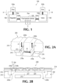
- FIGS. 2A and 2B example fluid ejection devices 205 are illustrated. These drawings show different components of fluid ejection device 205 in different examples. Fluid ejection devices 205 may be similar in structure and/or operation to fluid ejection device 105 in FIG. 1 . It is noted that the present description uses like element numbers to indicate elements and components that may be similar in structure and/or function. For example, an inkjet pen 100 in FIG. 1 may be similar in structure and/or operation to an inkjet pen 400, as shall be discussed hereinafter in relation to FIG. 4 . It is noted that portions of the description may refer to structure and/or operation of an implementation, While, in some cases, this discussion may apply to other figures and/or implementations, the reader will understand that this may not always be the case, as the context of the description may make clear.
- fluid ejection device 205 includes a support component 210 and a fluidic die 214.
- Support component 210 comprises a structure, such as a molded structure like a thermoplastic or an epoxy, that provides physical support to fluidic die 214.
- Support component 210 may be manufactured using a molding process, a machining process, or a layer build-up process, by way of example.
- Fluid slots 220a and 220b may carry printing fluids towards and/or away from fluidic die 214.
- Fluidic die 214 may comprise a semiconductor material and may include a number of layers making up fluid channels and slots (e.g., fluid feed holes 218a and 218b), ejection chambers, and nozzles (e.g., nozzles 224 in FIG. 2B ). Fluidic die 214 may also include ejection components, such as resistive components or piezoelectric membranes, by way of example, that may be activated to eject printing fluid from the nozzles.
- ejection components such as resistive components or piezoelectric membranes, by way of example, that may be activated to eject printing fluid from the nozzles.
- fluid channel 212 may be defined by a gap in support component 210 and/or a gap in adhesive layer 216. Fluid channel 212 may be used to enable circulation of printing fluid, such as illustrated by arrows A, B, and C, in FIG. 2A .
- an inkjet pen may include a support component (e.g., support component 210) connected to a fluidic die (e.g., fluidic die 214).
- a fluid channel e.g., fluid channel 212
- the backside of the fluidic die refers to the surface of fluidic die between the fluidic die and the support component. As such, in some examples, printing fluid flowing through the fluid channel may flow in contact with the backside of the fluidic die.
- the fluidic die may comprise a plurality of fluid feed holes (e.g., fluid feed holes 218a and 218b) and the fluid channel is arranged to be in fluid communication with the plurality of fluid feed holes.
- fluid feed holes e.g., fluid feed holes 218a and 218b
- the fluid ejection device may also provide fluid circulation within microfluidic channels within the die, as shall be illustrated by FIG. 2B .
- fluidic die 214 may be similar in structure and/or operation to fluidic die 214 of FIG. 2A
- adhesive layer 216 may be similar in structure and/or operation to adhesive layer 216 of FIG. 2A
- support component 210 may be similar in structure and/or operation to support component 210 of FIG. 2A.
- FIG. 2B also illustrates fluid slots 220a and 220b, fluid channel 212, and fluid feed holes 218a and 218b, which are similar in structure and/or operation to those discussed in relation to FIG. 2A .
- fluid channel 212 The combination of fluid channel 212, fluid slots 220a and 220b, and fluid feed holes 218a and 218b may be referred to collectively as a fluid flow path 222, as illustrated by arrows, A and B. Additionally, fluid may be ejected from nozzles, such as nozzle 224, as illustrated by arrow C.
- An example ejection component 225 is illustrated in proximity to a different nozzle and is intended to contemplate thermal-based ejection elements, piezo-based ejection elements, and the like. It is to be understood that ejection elements, such as ejection component 225, may be arranged in each ejection chamber from which it may be desired to eject printing fluid.
- fluid feed holes 218a and 218b in FIG. 2B are also in fluid communication within fluidic die 214 (e.g., within microchannels).
- printing fluid may enter an ejection chamber via a first fluid feed hole (e.g., fluid feed hole 218a), traverse an ejection chamber, and a portion of the printing fluid that is not ejected may subsequently flow out of the firing chamber and the fluidic die via a second fluid feed hole (e.g., fluid feed hole 218b).
- This fluidic path is illustrated by arrow B.
- one or more circulation components may be arranged within fluidic die 214 in order to cause printing fluid to enter fluid feed hole 218a from fluid channel 212. Additionally (or alternatively), activation of ejection components (e.g., resistive elements) may exert a fluidic pressure within the fluid path illustrated by arrow B to cause fluid (e.g., all or part of the fluid indicated by the arrow A) to enter fluid feed hole 218a.
- ejection components e.g., resistive elements
- Such circulation may be enabled by activation of a circulation component 227, by way of example.
- Circulation component 227 may comprise a resistive component, such as an embedded resistor, that may generate heat in response to current flow. Activation of circulation component 227 may facilitate fluid circulation, such as illustrated by arrow B.
- circulation component 227 may be arranged within other fluid feed holes to facilitate circulation. It may be in some cases that fluid may circulate through individual microchannels, as opposed to circulating through all ejection chambers concurrently. In other implementations, rather than using circulation components 227, due to external pressure (e.g., due to a pump external to fluid ejection device 205), printing fluid may be forced to enter fluid feed hole 218a.
- the combination of a plurality of fluid ports e.g., fluid ports 102a and 102b in FIG. 1
- a regulator e.g., regulator 106 in FIG. 1
- a valve e.g., valve 108 in FIG. 1
- fluid ejection device 205 may enable circulation of printing fluid without a decrease in fluid flux.
- printing fluid entering fluid ejection device 205 may be caused to be both ejected (in part) and to recirculate (in part).
- printing fluid may enter a fluid slot (e.g., fluid slot 220a), may travel through a fluid channel 212, and may exit the fluid ejection device via another fluid slot (e.g., second fluid slot 220b).
- a portion of the printing fluid may be ejected from a fluidic die (e.g., fluidic die 214) via a nozzle (e.g., a nozzle 224), as illustrated by arrow C.
- Another portion of the printing fluid may be caused to circulate away from an ejection chamber and out of fluid ejection device 205 (e.g., as illustrated by the portion of arrow B traversing fluid feed hole 218b and the portion of arrow A traversing fluid channel 212 and fluid slot 220b).
- the circulation of printing fluid out of fluid ejection device 205 may be in response to application of a negative pressure, activation of a circulation element, activation of a plurality of ejection elements, or a combination thereof.
- the next drawings focus on the support structure that enables flow of printing fluid in proximity to a back surface of a fluidic die.
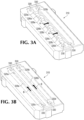
- FIG. 3A illustrates an implementation in which fluid channels traverse a width of fluidic dies
- FIG. 3B illustrates an implementation in which fluid channels traverse a length of fluidic dies
- FIGS. 3A and 3B may include components similar to those discussed previously.
- a support component 310 may be similar to support components 210 illustrated in FIGS. 2A and 2B
- fluid slots 320a and 320b may be similar to fluid slots 220a and 220b in FIGS. 2A and 2B .
- FIGS. 3A and 3B also show example die supports 330 that may support and/or secure fluidic dies (not shown; see, e.g., fluidic die 214 in FIGS. 2A and 2B ) into support component 310 and/or provide protection against potentially damaging contact (e.g., by media, by a service blade, etc.).
- fluidic die 214 in FIGS. 2A and 2B
- FIGS. 3A and 3B also show example die supports 330 that may support and/or secure fluidic dies (not shown; see, e.g., fluidic die 214 in FIGS. 2A and 2B ) into support component 310 and/or provide protection against potentially damaging contact (e.g., by media, by a service blade, etc.).
- Support component 310 may include gaps 326a-326d within the structure, such as to allow printing fluid to flow from fluid slot 320a to fluid slot 320b, as illustrated by arrows A. It should be understood that gaps 326a-326d may correspond to fluid channel 212 in FIG. 2B , by way of example. Additionally, adhesive dots may be applied to support surfaces 328a-328c to secure the fluidic die to support component 310. in one example, there may be gaps in the adhesive layer corresponding to gaps 326a-326d. In some cases, a fluid channel (e.g., fluid channel 212 in FIG. 2B ) may be formed along a backside of a fluidic die without gaps 326a-326d. For instance, if a sufficiently thick adhesive layer is applied, gaps in the adhesive layer (e.g., similar to gaps 326a-326d in support component 310) between adhesive dots may be sufficient to form a fluid channel
- FIG. 3B illustrates an example in which fluid channels are arranged to run lengthwise across a back surface of the fluidic die.
- FIG. 3B illustrates components that are similar to those discussed in FIG. 3A , including support component 310, fluid slots 320a-d, gaps 326a and 326b, and die supports 330. Nevertheless, gaps 326a and 326d are arranged with respect to fluidic dies such that printing fluid will enter gaps 326a and 326b (corresponding to, for instance, fluid channel 212 of FIGS. 2A and 2B ) by fluid slots 320c and 320d. The printing fluid will traverse the length of the backside of the fluidic die, and will exit gaps 326a and 326b via fluid slots 320a and 320b.
- more than one pair of input and output ports may be formed within a gap (e.g., gap 326a). For instance, along one channel defined by a gap, there may be a first input port followed by a first output port, then a second input port followed by a second output port, etc. Such an implementation may be desirable to reduce a pressure drop along the length of the fluid channel defined by the gap in support component 310.
- FIG. 4 illustrates an example fluid pen, including those structures discussed above, in relation to FIGS. 1-3B ,
- FIG. 4 illustrates an inkjet pen 400 and illustrates a flow of printing fluid in through a first fluid port and out of a second fluid port (e.g., fluid ports 102a and 102b in FIG. 1 ), where fluid flow out of pen 400 is illustrated by broken arrows and fluid flow into pen 400 is illustrated by solid arrows.
- a cap 450 refers to a structural component to enclose a top portion of pen 400, and may be in a suitable material including, but not limited to, thermoplastics.
- a filter 432 may be arranged in a fluidic plate 452 designed to facilitate directing fluid flow into and out of pen 400. For example, due, among other things, to recirculation of printing fluid, colorants may stick together and increase in size.
- filter 432 which may comprise a screen or a membrane, by way of non-limiting example, and may remove the undesirable particles (e.g., colorants, debris, etc.) from the printing fluid.
- Suitable materials for fluidic plate 452 may include thermoplastics, ceramics, glass, and metals, by way of non-limiting example.
- valve 408 and regulator 406 may be arranged within a body 454; valve 408 may enable flow of printing fluid out of pen 400; and regulator 406 may maintain flux for printing fluid entering fluid ejection device 405.
- a carrier 456 may act as a support structure, such as including support compound 210 discussed above in FIGS. 2A and 2B .
- Carrier 456 may include other components, including a fluid fan-out manifold, by way of non-limiting example.
- An adhesive layer 416 is illustrated as by connect carrier 456 to fluid ejection device 405.
- one pen 400 may house a fluid line and supporting components (such as a filter, a pressure regulator, a check valve, etc.) for a single color printing fluid (e.g., black). Additional pens may be used to support fluid lines for additional colors of printing fluid (e.g., cyan, magenta, yellow, white, etc.).
- a fluid line and supporting components such as a filter, a pressure regulator, a check valve, etc.
- Additional pens may be used to support fluid lines for additional colors of printing fluid (e.g., cyan, magenta, yellow, white, etc.).
- FIGS. 2A, 2B , 3A, 3B , and 4 will discuss how the elements of FIGS. 2A, 2B , 3A, 3B , and 4 may operate together in order to enable fluid circulation within a pen while the pen is active (e.g., ejecting fluid) without reductions in printing fluid flux.
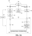
- FIGS. 5A and 5B illustrate example printing fluid delivery systems 501 configured to enable circulation of printing fluid, such as across a backside of a fluidic die, without a reduction in flux, such as using an inkjet pen 500, similar in structure and/or operation to inkjet pen 100 in FIG. 1 .
- Fluid ejection devices 505 may be similar in function and/or operation to fluid ejection device 105 in FIG. 1 and fluid ejection devices 205 in FIGS. 2A and 2B .
- Regulator 506 may be similar in structure and/or operation to regulator 106 in FIG. 1 .
- valve 508 may be similar in structure and/or operation to valve 108 in FIG. 1 .
- FIG. 5A also illustrates a filter 532, a printing fluid supply 534, a pump 536 (e.g., for pressurization at a first port), a pump 538 (e.g., for creating a vacuum at a second port), a pressure regulator 540, a flow restrictor 542, an input pressure regulator 544, and a thermal regulating component 546.
- a controller 507 may be in communication (e.g., via electrical signals exchanged) with components of printing fluid delivery system 501.
- printing fluid supply 534 refers to a reservoir capable of receiving, storing, and releasing printing fluid.
- printing fluid may exit printing fluid supply 534 and may traverse fluid supply lines towards pen 500. Printing fluid that is not ejected by pen 500 may be recirculated back to printing fluid supply 534, as illustrated.
- Pump 536 may be capable of applying a positive pressure on a fluid supply line, such as to cause printing fluid to flow towards pen 500.
- Pump 536 may take any suitable form including electromechanical and solid-state pumps, by way of non-limiting example.
- a subloop through input pressure regulator 544 may be used to help maintain constant input pressure at fluid port 502a.
- input pressure regulator 540 may comprise a gate to dynamically open and/or close based on pressure on a fluid line after pump 536.
- Thermal regulating component 546 refers to components capable of heating and/or chilling printing fluid prior to transmission thereof to pen 500.
- a thermal regulating component 546 may be desirable to yield a desired print quality (PQ).
- printing fluid may enter pen 500 via a first fluid port 502a, similar to as has been discussed above.
- Printing fluid may flow through filter 532 in order to remove any solids or debris exceeding a desired size, as discussed above.
- a filter e.g., filter 532
- a pressure regulator e.g., regulator 506
- a portion of the printing fluid may be ejected via fluid ejection devices 505, as discussed above, and may be allowed to flow out of fluid port 502b as valve 508 is opened, such as in response to application of a negative pressure.
- negative pressure may be applied to valve 508 by pump 538.
- Pump 538 may comprise any suitable form of electromechanical or solid-state component (among other things) capable of applying a negative pressure on fluid port 502b.
- Flow restrictor 542 and regulator 540 may work in concert to ensure that a vacuum pressure does not exceed an acceptable threshold at port 502b analogously to the operation of regulator 506 and input pressure regulator 544. For example, if excessive pressure were to be applied by pump 538, a flux of printing fluid may exceed a threshold for providing acceptable pressure to fluid ejection devices 505. And flow restrictor 542 and regulator 540 may reduce such an occurrence.
- controller 507 may be capable of enabling the operation of components, as discussed above, such as by transmitting signals to a desired component, such as via an electrical contact of a pen. Once received by the pen, the signals may be transmitted to enable operation, such as discussed above (e.g., causing ejection of printing fluid from a fluid ejection device).
- FIG. 5B includes components similar in structure and/or operation to those discussed in FIG. 5A .
- FIG. 5B illustrates an inkjet pen 500, in fluid communication with a printing fluid supply 534, a pump 536, a thermal regulating component 546, a pressure regulator 544, a vacuum regulator 540, and a vacuum pump 538
- FIG. 5B also illustrates a degas component 548, capable of removing gasses from printing fluid, such as by allowing air bubbles to separate from the fluid and be vented elsewhere.
- FIG. 5B also shows an inlet trunk line 503a through which printing fluid flows, after being pumped from pump 536.
- Printing fluid enters a number of fluid ejection devices 505 for ejection via fluidic lines and a first fluid port 502a.
- Printing fluid that is not ejected by fluid ejection devices 505 may be recirculated back towards printing fluid supply 534 via second fluid port 502b, may traverse a flow restrictor 542, and be directed to another fluid trunk line, this time an outlet trunk line 503b.
- a valve in fluid ejection devices 505 may enable flow of printing fluid out of second fluid port 502, even while printing, without a reduction in flux.
- FIG. 6 illustrates a method 600 including blocks 605, 610, and 615.
- a printing fluid is caused to enter a pen (e.g., pen 500 of FIG. 5A ) via a first port (e.g., fluid port 502a of FIG. 5A ).
- fluid flow may be engendered responsive to operation of a pump, activation of ejection components, and activation of circulation components, by way of non-limiting example.
- the printing fluid is to traverse a pressure regulator (e.g., regulator 506 of FIG. 5A ) and enter a fluid ejection device (e.g., fluid ejection device 505).
- a pressure regulator e.g., regulator 506 of FIG. 5A
- a fluid ejection device e.g., fluid ejection device 505
- a plurality of ejection elements are activated in the fluid ejection device to cause a first portion of the printing fluid to exit the fluid ejection device (see, e.g., arrow C in FIG. 2B ).
- a negative pressure is applied to a valve (e.g., valve 508 in FIG. 5A ) in fluid communication with a second port (e.g., second fluid port 502b in FIG. 5A ) of the pen to cause a second portion of the printing fluid to circulate across the back surface of the fluid ejection device (see, e.g., a second portion of arrow A in FIG. 2B ) and to exit the pen while the plurality of ejection elements are being activated.
- a valve e.g., valve 508 in FIG. 5A
- a second port e.g., second fluid port 502b in FIG. 5A
- the present disclosure proposes an approach for circulating fluid (e.g., behind a fluidic die) within a printing fluid ejection pen, while the pen is active (e.g., ejecting fluid) without drops in printing fluid flux.
Landscapes
- Ink Jet (AREA)
- Multiple-Way Valves (AREA)
Claims (15)
- Stylo à jet d'encre (100, 400, 500) comprenant :une pluralité de ports de fluide, un premier port de fluide (102a, 502a) conçu pour fournir du fluide d'impression à un dispositif d'éjection de fluide (105, 205, 505) à partir d'une réserve de fluide d'impression (534) et un second port de fluide (102b, 502b) pour diriger le fluide d'impression vers l'extérieur du stylo ;un régulateur de pression (106, 406, 506) en communication fluidique avec le premier port de fluide (102a, 502a) de la pluralité de ports de fluide ; etune valve (108, 408, 508) en communication fluidique avec le second port de fluide (102b, 502b) de la pluralité de ports de fluide ;dans lequel, en réponse à une pression négative, la valve (108, 408, 508) est conçue pour s'ouvrir afin de permettre au fluide à l'intérieur du stylo qui n'est pas éjecté par le dispositif d'éjection de fluide (105, 205, 505) d'être recirculé vers la réserve de fluide d'impression (534) par le biais du second port de fluide (102b, 502b).
- Stylo à jet d'encre (100, 400, 500) selon la revendication 1, comprenant en outre :un composant de support (210, 310) relié à une matrice fluidique (214) du dispositif d'éjection de fluide (105, 205, 405, 505) ; etun canal fluidique (212) agencé dans le composant de support (210, 310) à proximité d'une face arrière de la matrice fluidique (214).
- Stylo à jet d'encre (100, 400, 500) selon la revendication 2, dans lequel la matrice fluidique (214) comprend une pluralité de trous d'alimentation en fluide (218a, 218b) et le canal fluidique (212) est en communication fluidique avec la pluralité de trous d'alimentation en fluide (218a, 218b).
- Stylo à jet d'encre (100, 400, 500) selon la revendication 2, dans lequel le canal fluidique (212) est formé dans les interstices d'une couche adhésive (216, 416), dans les interstices d'un support moulé, ou dans une combinaison de ceux-ci.
- Stylo à jet d'encre (100, 400, 500) selon la revendication 2, dans lequel le canal fluidique (212) est agencé par rapport à la face arrière de la matrice fluidique (214) de manière à ce que les fluides s'écoulent en contact avec la face arrière de la matrice fluidique (214).
- Stylo à jet d'encre (100, 400, 500) selon la revendication 2, dans lequel le canal fluidique (212) est agencé dans le sens de la longueur par rapport à la face arrière de la matrice fluidique (214).
- Stylo à jet d'encre (100, 400, 500) selon la revendication 1, dans lequel la valve (108, 408, 508) comprend un clapet anti-retour (108, 408, 508).
- Stylo à jet d'encre (100, 400, 500) selon la revendication 1 comprenant en outre un filtre (432, 532) en communication fluidique avec le régulateur de pression (106, 406, 506).
- Procédé permettant de faire circuler des fluides d'impression à travers une surface arrière d'un dispositif d'éjection de fluide (105, 205, 405, 505) à l'intérieur d'un stylo à jet d'encre (100, 400, 500), le procédé comprenant :l'introduction d'un fluide d'impression dans le stylo par un premier port, le fluide d'impression traversant un régulateur de pression (106, 406, 506) et entrant dans un dispositif d'éjection de fluide (105, 205, 405, 505) ;l'activation d'une pluralité d'éléments d'éjection dans le dispositif d'éjection de fluide (105, 205, 405, 505) pour faire sortir une première partie du fluide d'impression du dispositif d'éjection de fluide (105, 205, 405, 505) ; et caractérisé en ce quel'application d'une pression négative à une valve (108, 408, 508) en communication fluidique avec un second port du stylo pour faire circuler une deuxième partie du fluide d'impression à travers la surface arrière d'une matrice fluidique (214) du dispositif d'éjection de fluide (105, 205, 405, 505) et la faire sortir du stylo alors que la pluralité d'éléments d'éjection est activée.
- Procédé selon la revendication 9, dans lequel le fluide d'impression pénètre dans le stylo à partir d'un composant de régulation thermique (546).
- Procédé selon la revendication 9 consistant en outre à faire circuler une troisième partie du fluide d'impression qui n'est pas éjectée du dispositif d'éjection de fluide (105, 205, 405, 505) hors d'une chambre d'éjection du dispositif d'éjection de fluide (105, 205, 405, 505) et vers le second port, la circulation de la troisième partie du fluide d'impression se faisant en réponse à l'application de la pression négative, à l'activation d'un élément de circulation, à l'activation de la pluralité d'éléments d'éjection, ou à une combinaison de ces éléments.
- Procédé selon la revendication 9, dans lequel l'introduction du fluide d'impression dans le stylo consiste à faire passer le fluide d'impression à travers un filtre (432, 532).
- Procédé selon la revendication 9, dans lequel l'application de la pression négative à la valve (108, 408, 508) comprend l'application d'un vide dépassant un seuil pour ouvrir la valve (108, 408, 508).
- Dispositif d'impression comprenant :un stylo (100, 400, 500) comprenant une pluralité de dispositifs d'éjection de fluide (105, 205, 405, 505), un premier port de fluide (102a, 502a) et un second port de fluide (102b, 502b), et un contact électrique, dans lequel les premier et second ports de fluide (102b, 502b) sont en communication fluidique avec la pluralité de dispositifs d'éjection de fluide (105, 205, 405, 505) et la pluralité de dispositifs d'éjection de fluide (105, 205, 505) comprend un certain nombre de matrices fluidiques (214) ;un régulateur de pression (106, 406, 506) en communication fluidique avec le premier port de fluide (102a, 502a) ;un clapet anti-retour (108, 408, 508) en communication fluidique avec le second port de fluide (102b, 502b) ; etune réserve d'alimentation en fluide d'impression également en communication fluidique avec le premier port de fluide (102a, 502a) ;le contact électrique est configuré pour recevoir des signaux d'un dispositif de commande afin de provoquer l'éjection de fluide d'impression à partir de la pluralité de dispositifs d'éjection de fluide (105, 205, 405, 505) ;dans lequel, en réponse à l'application d'une pression positive au premier port de fluide (102a, 502a) et d'une pression négative au second port de fluide (102b, 502b), le fluide d'impression doit s'écouler le long d'une partie de la face arrière de matrices fluidiques de la pluralité de dispositifs d'éjection de fluide (105, 205, 405, 505) et sortir du stylo par le biais du second port de fluide (102b, 502b) tandis que le fluide d'impression est éjecté de la pluralité de dispositifs d'éjection de fluide (105, 205, 405, 505).
- Dispositif d'impression selon la revendication 14 comprenant en outre un limiteur de débit (542) en communication fluidique avec le second port de fluide (102b, 502b).
Applications Claiming Priority (1)
| Application Number | Priority Date | Filing Date | Title |
|---|---|---|---|
| PCT/US2019/044492 WO2021021193A1 (fr) | 2019-07-31 | 2019-07-31 | Circulation de fluide d'impression |
Publications (3)
| Publication Number | Publication Date |
|---|---|
| EP4003739A1 EP4003739A1 (fr) | 2022-06-01 |
| EP4003739A4 EP4003739A4 (fr) | 2023-04-26 |
| EP4003739B1 true EP4003739B1 (fr) | 2025-01-08 |
Family
ID=74229540
Family Applications (1)
| Application Number | Title | Priority Date | Filing Date |
|---|---|---|---|
| EP19939404.0A Active EP4003739B1 (fr) | 2019-07-31 | 2019-07-31 | Circulation de fluide d'impression |
Country Status (4)
| Country | Link |
|---|---|
| US (1) | US11807019B2 (fr) |
| EP (1) | EP4003739B1 (fr) |
| CN (1) | CN114144311B (fr) |
| WO (1) | WO2021021193A1 (fr) |
Family Cites Families (21)
| Publication number | Priority date | Publication date | Assignee | Title |
|---|---|---|---|---|
| US6631983B2 (en) | 2000-12-28 | 2003-10-14 | Eastman Kodak Company | Ink recirculation system for ink jet printers |
| US6880926B2 (en) | 2002-10-31 | 2005-04-19 | Hewlett-Packard Development Company, L.P. | Circulation through compound slots |
| JP3952054B2 (ja) | 2004-09-28 | 2007-08-01 | 富士フイルム株式会社 | 画像形成装置 |
| JP4574385B2 (ja) | 2005-02-17 | 2010-11-04 | キヤノン株式会社 | インクジェット記録ヘッドおよび記録装置 |
| AU2006201083B2 (en) * | 2006-03-15 | 2008-07-31 | Memjet Technology Limited | Pulse damped fluidic architecture |
| CN101287606B (zh) * | 2006-03-03 | 2010-11-03 | 西尔弗布鲁克研究有限公司 | 脉冲阻尼射流结构 |
| US7862138B2 (en) | 2007-10-04 | 2011-01-04 | Hewlett-Packard Development Company, L.P. | Flow control in an ink pen |
| GB0724606D0 (en) | 2007-12-18 | 2008-01-30 | Xennia Technology Ltd | Recirculating ink system for industrial inkjet printing |
| JP5235436B2 (ja) | 2008-02-04 | 2013-07-10 | キヤノン株式会社 | インクジェット記録装置 |
| US8876242B2 (en) | 2009-05-08 | 2014-11-04 | Canon Kabushiki Kaisha | Liquid ejection head |
| EP2629976B1 (fr) | 2010-10-19 | 2021-04-21 | Hewlett-Packard Development Company, L.P. | Module d'impression à deux régulateurs |
| JP5425850B2 (ja) | 2011-09-14 | 2014-02-26 | 東芝テック株式会社 | インクジェットヘッド |
| US8714721B2 (en) | 2012-04-02 | 2014-05-06 | Xerox Corporation | Compliant liquid path member and receptacle for ink recirculation |
| US9375928B2 (en) | 2013-01-31 | 2016-06-28 | Hewlett-Packard Development Company, L.P. | Fluid ejection device with mixing beads |
| WO2014178830A1 (fr) | 2013-04-30 | 2014-11-06 | Hewlett-Packard Development Company, L.P. | Dispositif d'éjection de fluide doté d'un pont de trou d'alimentation en encre |
| US9895888B2 (en) * | 2014-04-22 | 2018-02-20 | Hewlett-Packard Development Company, L.P. | Fluid flow structure |
| PT3344459T (pt) * | 2015-09-02 | 2019-12-11 | Tonejet Ltd | Método de funcionamento de uma cabeça de impressão de jacto de tinta |
| WO2017098962A1 (fr) * | 2015-12-11 | 2017-06-15 | コニカミノルタ株式会社 | Tête à jet d'encre et dispositif d'enregistrement à jet d'encre |
| US9925791B2 (en) * | 2016-01-08 | 2018-03-27 | Canon Kabushiki Kaisha | Liquid ejection apparatus and liquid ejection head |
| WO2019103752A1 (fr) * | 2017-11-27 | 2019-05-31 | Hewlett-Packard Development Company, L.P. | Canaux transversaux de recirculation de matrice et canaux de recirculation de chambre |
| US10906320B2 (en) * | 2019-04-30 | 2021-02-02 | Hewlett-Packard Development Company, L.P. | Standpipe crossflow circulation |
-
2019
- 2019-07-31 WO PCT/US2019/044492 patent/WO2021021193A1/fr not_active Ceased
- 2019-07-31 US US17/312,366 patent/US11807019B2/en active Active
- 2019-07-31 EP EP19939404.0A patent/EP4003739B1/fr active Active
- 2019-07-31 CN CN201980099005.5A patent/CN114144311B/zh active Active
Also Published As
| Publication number | Publication date |
|---|---|
| WO2021021193A1 (fr) | 2021-02-04 |
| US20220161568A1 (en) | 2022-05-26 |
| EP4003739A1 (fr) | 2022-06-01 |
| EP4003739A4 (fr) | 2023-04-26 |
| CN114144311B (zh) | 2023-05-16 |
| US11807019B2 (en) | 2023-11-07 |
| CN114144311A (zh) | 2022-03-04 |
Similar Documents
| Publication | Publication Date | Title |
|---|---|---|
| JP5731657B2 (ja) | デュアルレギュレータ印刷モジュール | |
| US9833994B2 (en) | Inkjet head that circulates ink | |
| US9694582B1 (en) | Single jet recirculation in an inkjet print head | |
| US10118390B2 (en) | Single jet recirculation in an inkjet print head | |
| KR20190000795A (ko) | 액체 토출 헤드 및 액체 토출 장치 | |
| CN110891792B (zh) | 具有封闭式横向通道的流体喷射装置 | |
| CN110891793B (zh) | 具有封闭式横向通道的流体喷射管芯 | |
| US11225074B2 (en) | Fluidic dies with inlet and outlet channels | |
| US11046073B2 (en) | Fluid ejection die heat exchangers | |
| EP4003739B1 (fr) | Circulation de fluide d'impression | |
| US12138937B2 (en) | Printing fluid circulation | |
| EP3535131B1 (fr) | Structure d'écoulement de fluide | |
| JP2017209967A (ja) | インクジェットヘッド及びインクジェット記録装置 | |
| US11970010B2 (en) | Printhead with circulation channel | |
| EP3356148B1 (fr) | Têtes d'impression |
Legal Events
| Date | Code | Title | Description |
|---|---|---|---|
| STAA | Information on the status of an ep patent application or granted ep patent |
Free format text: STATUS: THE INTERNATIONAL PUBLICATION HAS BEEN MADE |
|
| PUAI | Public reference made under article 153(3) epc to a published international application that has entered the european phase |
Free format text: ORIGINAL CODE: 0009012 |
|
| STAA | Information on the status of an ep patent application or granted ep patent |
Free format text: STATUS: REQUEST FOR EXAMINATION WAS MADE |
|
| 17P | Request for examination filed |
Effective date: 20210930 |
|
| AK | Designated contracting states |
Kind code of ref document: A1 Designated state(s): AL AT BE BG CH CY CZ DE DK EE ES FI FR GB GR HR HU IE IS IT LI LT LU LV MC MK MT NL NO PL PT RO RS SE SI SK SM TR |
|
| DAV | Request for validation of the european patent (deleted) | ||
| DAX | Request for extension of the european patent (deleted) | ||
| A4 | Supplementary search report drawn up and despatched |
Effective date: 20230323 |
|
| RIC1 | Information provided on ipc code assigned before grant |
Ipc: B41J 29/38 20060101ALI20230317BHEP Ipc: B41J 2/175 20060101AFI20230317BHEP |
|
| GRAP | Despatch of communication of intention to grant a patent |
Free format text: ORIGINAL CODE: EPIDOSNIGR1 |
|
| STAA | Information on the status of an ep patent application or granted ep patent |
Free format text: STATUS: GRANT OF PATENT IS INTENDED |
|
| INTG | Intention to grant announced |
Effective date: 20241022 |
|
| GRAS | Grant fee paid |
Free format text: ORIGINAL CODE: EPIDOSNIGR3 |
|
| GRAA | (expected) grant |
Free format text: ORIGINAL CODE: 0009210 |
|
| STAA | Information on the status of an ep patent application or granted ep patent |
Free format text: STATUS: THE PATENT HAS BEEN GRANTED |
|
| AK | Designated contracting states |
Kind code of ref document: B1 Designated state(s): AL AT BE BG CH CY CZ DE DK EE ES FI FR GB GR HR HU IE IS IT LI LT LU LV MC MK MT NL NO PL PT RO RS SE SI SK SM TR |
|
| REG | Reference to a national code |
Ref country code: GB Ref legal event code: FG4D |
|
| REG | Reference to a national code |
Ref country code: CH Ref legal event code: EP |
|
| REG | Reference to a national code |
Ref country code: DE Ref legal event code: R096 Ref document number: 602019064773 Country of ref document: DE |
|
| REG | Reference to a national code |
Ref country code: IE Ref legal event code: FG4D |
|
| REG | Reference to a national code |
Ref country code: LT Ref legal event code: MG9D |
|
| REG | Reference to a national code |
Ref country code: NL Ref legal event code: MP Effective date: 20250108 |
|
| REG | Reference to a national code |
Ref country code: AT Ref legal event code: MK05 Ref document number: 1758095 Country of ref document: AT Kind code of ref document: T Effective date: 20250108 |
|
| PG25 | Lapsed in a contracting state [announced via postgrant information from national office to epo] |
Ref country code: NL Free format text: LAPSE BECAUSE OF FAILURE TO SUBMIT A TRANSLATION OF THE DESCRIPTION OR TO PAY THE FEE WITHIN THE PRESCRIBED TIME-LIMIT Effective date: 20250108 |
|
| PG25 | Lapsed in a contracting state [announced via postgrant information from national office to epo] |
Ref country code: RS Free format text: LAPSE BECAUSE OF FAILURE TO SUBMIT A TRANSLATION OF THE DESCRIPTION OR TO PAY THE FEE WITHIN THE PRESCRIBED TIME-LIMIT Effective date: 20250408 |
|
| PG25 | Lapsed in a contracting state [announced via postgrant information from national office to epo] |
Ref country code: FI Free format text: LAPSE BECAUSE OF FAILURE TO SUBMIT A TRANSLATION OF THE DESCRIPTION OR TO PAY THE FEE WITHIN THE PRESCRIBED TIME-LIMIT Effective date: 20250108 |
|
| PG25 | Lapsed in a contracting state [announced via postgrant information from national office to epo] |
Ref country code: PL Free format text: LAPSE BECAUSE OF FAILURE TO SUBMIT A TRANSLATION OF THE DESCRIPTION OR TO PAY THE FEE WITHIN THE PRESCRIBED TIME-LIMIT Effective date: 20250108 |
|
| PG25 | Lapsed in a contracting state [announced via postgrant information from national office to epo] |
Ref country code: ES Free format text: LAPSE BECAUSE OF FAILURE TO SUBMIT A TRANSLATION OF THE DESCRIPTION OR TO PAY THE FEE WITHIN THE PRESCRIBED TIME-LIMIT Effective date: 20250108 |
|
| PG25 | Lapsed in a contracting state [announced via postgrant information from national office to epo] |
Ref country code: NO Free format text: LAPSE BECAUSE OF FAILURE TO SUBMIT A TRANSLATION OF THE DESCRIPTION OR TO PAY THE FEE WITHIN THE PRESCRIBED TIME-LIMIT Effective date: 20250408 Ref country code: IS Free format text: LAPSE BECAUSE OF FAILURE TO SUBMIT A TRANSLATION OF THE DESCRIPTION OR TO PAY THE FEE WITHIN THE PRESCRIBED TIME-LIMIT Effective date: 20250508 |
|
| PG25 | Lapsed in a contracting state [announced via postgrant information from national office to epo] |
Ref country code: HR Free format text: LAPSE BECAUSE OF FAILURE TO SUBMIT A TRANSLATION OF THE DESCRIPTION OR TO PAY THE FEE WITHIN THE PRESCRIBED TIME-LIMIT Effective date: 20250108 |
|
| PG25 | Lapsed in a contracting state [announced via postgrant information from national office to epo] |
Ref country code: LV Free format text: LAPSE BECAUSE OF FAILURE TO SUBMIT A TRANSLATION OF THE DESCRIPTION OR TO PAY THE FEE WITHIN THE PRESCRIBED TIME-LIMIT Effective date: 20250108 Ref country code: PT Free format text: LAPSE BECAUSE OF FAILURE TO SUBMIT A TRANSLATION OF THE DESCRIPTION OR TO PAY THE FEE WITHIN THE PRESCRIBED TIME-LIMIT Effective date: 20250508 |
|
| PG25 | Lapsed in a contracting state [announced via postgrant information from national office to epo] |
Ref country code: GR Free format text: LAPSE BECAUSE OF FAILURE TO SUBMIT A TRANSLATION OF THE DESCRIPTION OR TO PAY THE FEE WITHIN THE PRESCRIBED TIME-LIMIT Effective date: 20250409 Ref country code: BG Free format text: LAPSE BECAUSE OF FAILURE TO SUBMIT A TRANSLATION OF THE DESCRIPTION OR TO PAY THE FEE WITHIN THE PRESCRIBED TIME-LIMIT Effective date: 20250108 |
|
| PG25 | Lapsed in a contracting state [announced via postgrant information from national office to epo] |
Ref country code: AT Free format text: LAPSE BECAUSE OF FAILURE TO SUBMIT A TRANSLATION OF THE DESCRIPTION OR TO PAY THE FEE WITHIN THE PRESCRIBED TIME-LIMIT Effective date: 20250108 |
|
| PG25 | Lapsed in a contracting state [announced via postgrant information from national office to epo] |
Ref country code: SE Free format text: LAPSE BECAUSE OF FAILURE TO SUBMIT A TRANSLATION OF THE DESCRIPTION OR TO PAY THE FEE WITHIN THE PRESCRIBED TIME-LIMIT Effective date: 20250108 |
|
| PG25 | Lapsed in a contracting state [announced via postgrant information from national office to epo] |
Ref country code: SM Free format text: LAPSE BECAUSE OF FAILURE TO SUBMIT A TRANSLATION OF THE DESCRIPTION OR TO PAY THE FEE WITHIN THE PRESCRIBED TIME-LIMIT Effective date: 20250108 |
|
| REG | Reference to a national code |
Ref country code: DE Ref legal event code: R097 Ref document number: 602019064773 Country of ref document: DE |
|
| PG25 | Lapsed in a contracting state [announced via postgrant information from national office to epo] |
Ref country code: DK Free format text: LAPSE BECAUSE OF FAILURE TO SUBMIT A TRANSLATION OF THE DESCRIPTION OR TO PAY THE FEE WITHIN THE PRESCRIBED TIME-LIMIT Effective date: 20250108 |
|
| PGFP | Annual fee paid to national office [announced via postgrant information from national office to epo] |
Ref country code: DE Payment date: 20250620 Year of fee payment: 7 |
|
| PG25 | Lapsed in a contracting state [announced via postgrant information from national office to epo] |
Ref country code: CZ Free format text: LAPSE BECAUSE OF FAILURE TO SUBMIT A TRANSLATION OF THE DESCRIPTION OR TO PAY THE FEE WITHIN THE PRESCRIBED TIME-LIMIT Effective date: 20250108 Ref country code: EE Free format text: LAPSE BECAUSE OF FAILURE TO SUBMIT A TRANSLATION OF THE DESCRIPTION OR TO PAY THE FEE WITHIN THE PRESCRIBED TIME-LIMIT Effective date: 20250108 |
|
| PG25 | Lapsed in a contracting state [announced via postgrant information from national office to epo] |
Ref country code: RO Free format text: LAPSE BECAUSE OF FAILURE TO SUBMIT A TRANSLATION OF THE DESCRIPTION OR TO PAY THE FEE WITHIN THE PRESCRIBED TIME-LIMIT Effective date: 20250108 |
|
| PG25 | Lapsed in a contracting state [announced via postgrant information from national office to epo] |
Ref country code: SK Free format text: LAPSE BECAUSE OF FAILURE TO SUBMIT A TRANSLATION OF THE DESCRIPTION OR TO PAY THE FEE WITHIN THE PRESCRIBED TIME-LIMIT Effective date: 20250108 |
|
| PLBE | No opposition filed within time limit |
Free format text: ORIGINAL CODE: 0009261 |
|
| STAA | Information on the status of an ep patent application or granted ep patent |
Free format text: STATUS: NO OPPOSITION FILED WITHIN TIME LIMIT |
|
| REG | Reference to a national code |
Ref country code: CH Ref legal event code: L10 Free format text: ST27 STATUS EVENT CODE: U-0-0-L10-L00 (AS PROVIDED BY THE NATIONAL OFFICE) Effective date: 20251119 |
|
| 26N | No opposition filed |
Effective date: 20251009 |
|
| PG25 | Lapsed in a contracting state [announced via postgrant information from national office to epo] |
Ref country code: IT Free format text: LAPSE BECAUSE OF FAILURE TO SUBMIT A TRANSLATION OF THE DESCRIPTION OR TO PAY THE FEE WITHIN THE PRESCRIBED TIME-LIMIT Effective date: 20250108 |
|
| REG | Reference to a national code |
Ref country code: CH Ref legal event code: H13 Free format text: ST27 STATUS EVENT CODE: U-0-0-H10-H13 (AS PROVIDED BY THE NATIONAL OFFICE) Effective date: 20260224 |
|
| PG25 | Lapsed in a contracting state [announced via postgrant information from national office to epo] |
Ref country code: LU Free format text: LAPSE BECAUSE OF NON-PAYMENT OF DUE FEES Effective date: 20250731 |
|
| GBPC | Gb: european patent ceased through non-payment of renewal fee |
Effective date: 20250731 |
|
| REG | Reference to a national code |
Ref country code: BE Ref legal event code: MM Effective date: 20250731 |
|
| PG25 | Lapsed in a contracting state [announced via postgrant information from national office to epo] |
Ref country code: GB Free format text: LAPSE BECAUSE OF NON-PAYMENT OF DUE FEES Effective date: 20250731 |
|
| PG25 | Lapsed in a contracting state [announced via postgrant information from national office to epo] |
Ref country code: BE Free format text: LAPSE BECAUSE OF NON-PAYMENT OF DUE FEES Effective date: 20250731 |
|
| PG25 | Lapsed in a contracting state [announced via postgrant information from national office to epo] |
Ref country code: FR Free format text: LAPSE BECAUSE OF NON-PAYMENT OF DUE FEES Effective date: 20250731 |
|
| PG25 | Lapsed in a contracting state [announced via postgrant information from national office to epo] |
Ref country code: CH Free format text: LAPSE BECAUSE OF NON-PAYMENT OF DUE FEES Effective date: 20250731 |