EP4003761B1 - Reifen mit lauffläche - Google Patents
Reifen mit lauffläche Download PDFInfo
- Publication number
- EP4003761B1 EP4003761B1 EP20757643.0A EP20757643A EP4003761B1 EP 4003761 B1 EP4003761 B1 EP 4003761B1 EP 20757643 A EP20757643 A EP 20757643A EP 4003761 B1 EP4003761 B1 EP 4003761B1
- Authority
- EP
- European Patent Office
- Prior art keywords
- tread
- block
- incision
- pattern
- cutout
- Prior art date
- Legal status (The legal status is an assumption and is not a legal conclusion. Google has not performed a legal analysis and makes no representation as to the accuracy of the status listed.)
- Active
Links
Images




Classifications
-
- B—PERFORMING OPERATIONS; TRANSPORTING
- B60—VEHICLES IN GENERAL
- B60C—VEHICLE TYRES; TYRE INFLATION; TYRE CHANGING; CONNECTING VALVES TO INFLATABLE ELASTIC BODIES IN GENERAL; DEVICES OR ARRANGEMENTS RELATED TO TYRES
- B60C11/00—Tyre tread bands; Tread patterns; Anti-skid inserts
- B60C11/03—Tread patterns
- B60C11/0302—Tread patterns directional pattern, i.e. with main rolling direction
-
- B—PERFORMING OPERATIONS; TRANSPORTING
- B60—VEHICLES IN GENERAL
- B60C—VEHICLE TYRES; TYRE INFLATION; TYRE CHANGING; CONNECTING VALVES TO INFLATABLE ELASTIC BODIES IN GENERAL; DEVICES OR ARRANGEMENTS RELATED TO TYRES
- B60C1/00—Tyres characterised by the chemical composition or the physical arrangement or mixture of the composition
- B60C1/0016—Compositions of the tread
-
- B—PERFORMING OPERATIONS; TRANSPORTING
- B60—VEHICLES IN GENERAL
- B60C—VEHICLE TYRES; TYRE INFLATION; TYRE CHANGING; CONNECTING VALVES TO INFLATABLE ELASTIC BODIES IN GENERAL; DEVICES OR ARRANGEMENTS RELATED TO TYRES
- B60C11/00—Tyre tread bands; Tread patterns; Anti-skid inserts
- B60C11/03—Tread patterns
- B60C11/0318—Tread patterns irregular patterns with particular pitch sequence
-
- B—PERFORMING OPERATIONS; TRANSPORTING
- B60—VEHICLES IN GENERAL
- B60C—VEHICLE TYRES; TYRE INFLATION; TYRE CHANGING; CONNECTING VALVES TO INFLATABLE ELASTIC BODIES IN GENERAL; DEVICES OR ARRANGEMENTS RELATED TO TYRES
- B60C11/00—Tyre tread bands; Tread patterns; Anti-skid inserts
- B60C11/03—Tread patterns
- B60C11/12—Tread patterns characterised by the use of narrow slits or incisions, e.g. sipes
-
- C—CHEMISTRY; METALLURGY
- C08—ORGANIC MACROMOLECULAR COMPOUNDS; THEIR PREPARATION OR CHEMICAL WORKING-UP; COMPOSITIONS BASED THEREON
- C08K—Use of inorganic or non-macromolecular organic substances as compounding ingredients
- C08K3/00—Use of inorganic substances as compounding ingredients
- C08K3/34—Silicon-containing compounds
- C08K3/36—Silica
-
- C—CHEMISTRY; METALLURGY
- C08—ORGANIC MACROMOLECULAR COMPOUNDS; THEIR PREPARATION OR CHEMICAL WORKING-UP; COMPOSITIONS BASED THEREON
- C08L—COMPOSITIONS OF MACROMOLECULAR COMPOUNDS
- C08L15/00—Compositions of rubber derivatives
-
- C—CHEMISTRY; METALLURGY
- C08—ORGANIC MACROMOLECULAR COMPOUNDS; THEIR PREPARATION OR CHEMICAL WORKING-UP; COMPOSITIONS BASED THEREON
- C08L—COMPOSITIONS OF MACROMOLECULAR COMPOUNDS
- C08L57/00—Compositions of unspecified polymers obtained by reactions only involving carbon-to-carbon unsaturated bonds
- C08L57/02—Copolymers of mineral oil hydrocarbons
-
- C—CHEMISTRY; METALLURGY
- C08—ORGANIC MACROMOLECULAR COMPOUNDS; THEIR PREPARATION OR CHEMICAL WORKING-UP; COMPOSITIONS BASED THEREON
- C08L—COMPOSITIONS OF MACROMOLECULAR COMPOUNDS
- C08L9/00—Compositions of homopolymers or copolymers of conjugated diene hydrocarbons
- C08L9/06—Copolymers with styrene
-
- C—CHEMISTRY; METALLURGY
- C08—ORGANIC MACROMOLECULAR COMPOUNDS; THEIR PREPARATION OR CHEMICAL WORKING-UP; COMPOSITIONS BASED THEREON
- C08L—COMPOSITIONS OF MACROMOLECULAR COMPOUNDS
- C08L91/00—Compositions of oils, fats or waxes; Compositions of derivatives thereof
-
- B—PERFORMING OPERATIONS; TRANSPORTING
- B60—VEHICLES IN GENERAL
- B60C—VEHICLE TYRES; TYRE INFLATION; TYRE CHANGING; CONNECTING VALVES TO INFLATABLE ELASTIC BODIES IN GENERAL; DEVICES OR ARRANGEMENTS RELATED TO TYRES
- B60C11/00—Tyre tread bands; Tread patterns; Anti-skid inserts
- B60C11/0008—Tyre tread bands; Tread patterns; Anti-skid inserts characterised by the tread rubber
- B60C2011/0016—Physical properties or dimensions
-
- B—PERFORMING OPERATIONS; TRANSPORTING
- B60—VEHICLES IN GENERAL
- B60C—VEHICLE TYRES; TYRE INFLATION; TYRE CHANGING; CONNECTING VALVES TO INFLATABLE ELASTIC BODIES IN GENERAL; DEVICES OR ARRANGEMENTS RELATED TO TYRES
- B60C11/00—Tyre tread bands; Tread patterns; Anti-skid inserts
- B60C11/0008—Tyre tread bands; Tread patterns; Anti-skid inserts characterised by the tread rubber
- B60C2011/0016—Physical properties or dimensions
- B60C2011/0025—Modulus or tan delta
-
- B—PERFORMING OPERATIONS; TRANSPORTING
- B60—VEHICLES IN GENERAL
- B60C—VEHICLE TYRES; TYRE INFLATION; TYRE CHANGING; CONNECTING VALVES TO INFLATABLE ELASTIC BODIES IN GENERAL; DEVICES OR ARRANGEMENTS RELATED TO TYRES
- B60C11/00—Tyre tread bands; Tread patterns; Anti-skid inserts
- B60C11/03—Tread patterns
- B60C11/0311—Patterns comprising tread lugs arranged parallel or oblique to the axis of rotation
- B60C2011/0313—Patterns comprising tread lugs arranged parallel or oblique to the axis of rotation directional type
-
- B—PERFORMING OPERATIONS; TRANSPORTING
- B60—VEHICLES IN GENERAL
- B60C—VEHICLE TYRES; TYRE INFLATION; TYRE CHANGING; CONNECTING VALVES TO INFLATABLE ELASTIC BODIES IN GENERAL; DEVICES OR ARRANGEMENTS RELATED TO TYRES
- B60C11/00—Tyre tread bands; Tread patterns; Anti-skid inserts
- B60C11/03—Tread patterns
- B60C2011/0337—Tread patterns characterised by particular design features of the pattern
- B60C2011/0339—Grooves
- B60C2011/0374—Slant grooves, i.e. having an angle of about 5 to 35 degrees to the equatorial plane
-
- B—PERFORMING OPERATIONS; TRANSPORTING
- B60—VEHICLES IN GENERAL
- B60C—VEHICLE TYRES; TYRE INFLATION; TYRE CHANGING; CONNECTING VALVES TO INFLATABLE ELASTIC BODIES IN GENERAL; DEVICES OR ARRANGEMENTS RELATED TO TYRES
- B60C11/00—Tyre tread bands; Tread patterns; Anti-skid inserts
- B60C11/03—Tread patterns
- B60C11/12—Tread patterns characterised by the use of narrow slits or incisions, e.g. sipes
- B60C2011/129—Sipe density, i.e. the distance between the sipes within the pattern
-
- B—PERFORMING OPERATIONS; TRANSPORTING
- B60—VEHICLES IN GENERAL
- B60C—VEHICLE TYRES; TYRE INFLATION; TYRE CHANGING; CONNECTING VALVES TO INFLATABLE ELASTIC BODIES IN GENERAL; DEVICES OR ARRANGEMENTS RELATED TO TYRES
- B60C11/00—Tyre tread bands; Tread patterns; Anti-skid inserts
- B60C11/03—Tread patterns
- B60C11/12—Tread patterns characterised by the use of narrow slits or incisions, e.g. sipes
- B60C2011/129—Sipe density, i.e. the distance between the sipes within the pattern
- B60C2011/1295—Sipe density, i.e. the distance between the sipes within the pattern variable
Definitions
- the present invention relates to a tire for a motor vehicle, the tread of which comprises a plurality of oblique grooves having a strong slenderness.
- the invention is more particularly suitable for a tire intended to equip a passenger vehicle or a van.
- a tire intended to equip a motor vehicle comprises a tread.
- This tread comprises a tread surface and two edges delimiting said tread surface.
- the running surface corresponds to all the points of the tread which come into contact with a road surface when the tire, inflated to its reference pressure and crushed by a reference load, rolls on this road surface.
- the reference inflation pressure and the reference load are defined in the conditions of use of the tire, conditions specified in particular by the ETRTO standard.
- the running surface of the tread includes depressions formed by various grooves, such as oblique grooves.
- the oblique grooves form channels intended to evacuate water on the sides of the tread. It is known from the document GB2240522 a directional tread comprising a plurality of oblique grooves.
- the tread comprises a central axis X and two edges which frame said tread and which determine a tread width, denoted A on the figure 1 .
- the tread also has a central part of width denoted K and which corresponds to approximately 80% of the width A of the tread.
- each oblique groove has a large slenderness, that is to say that the projection in the circumferential direction X of said groove is very close to or even greater than half the width K of this central part.
- the very large slenderness of the oblique grooves improves the evacuation of water out of the tread and therefore improves grip on wet ground.
- the present invention aims to remedy this drawback.
- the present invention aims to improve the grip compromise on snowy ground/wet ground for an all-season tire while improving the wear performance of such a tire.
- the invention relates to a tire comprising a directional tread.
- trimer is understood to mean all types of tire made of rubber material subjected to internal pressure when driving or not subjected to such internal pressure when driving (this is the case of a tire without compressed air, for example, Tweel TM type).
- rubber material is meant a diene elastomer, that is to say in known manner an elastomer derived from at least in part (that is to say homopolymer or copolymer) of diene monomers (monomers carrying carbon-carbon double bonds, conjugated or not).
- tread of a tire is meant a quantity of rubber material delimited by a tread surface.
- the running surface groups together all the points of the tire which will come into contact with the ground under normal driving conditions.
- the “usual driving conditions” are the conditions of use defined by the ETRTO standard (European Tire and Rim Technical Organisation). These conditions of use specify the reference inflation pressure corresponding to the load capacity of the tire indicated by its load index and its speed code. These conditions of use can also be called “nominal conditions” or “conditions of use”.
- Directional tread means a tread whose tread elements are specifically arranged to optimize the behavioral characteristics as a function of a predetermined direction of rotation. This direction of rotation is conventionally indicated by an arrow on the sidewall of the tire.
- the tread of the invention comprises a central axis and two edges flanking said central axis and determining a tread width W, the width of the tread being greater than or equal to 140 mm.
- This tread width is determined from a dynamically generated footprint.
- black ink is deposited on part of the tread of the tire and this inked part is rolled on a sheet of paper at a certain forward speed.
- the conditions for making such an imprint are at nominal pressure, for a load corresponding to 0.76 times the nominal load and at a forward speed of 100 mm/s. For example, for a tire of size 205/55R16 91V, the conditions for making the footprint will be at a pressure of 2.5 bar and for a load of 480 daN. All the measurements for determining the slenderness E, the density of incisions SD, the average density of incisions SDmoy are then made from an imprint of the tread rolling on a support under the load, pressure and forward speed conditions as described above.
- the tread comprises a plurality of patterns which follow one another in the circumferential direction, each pattern having a pitch P.
- “By pattern” is meant a set of blocks which is repeated in the circumferential direction. This repetition can be done at iso-dimension.
- the tread is then said to be single-pitch. As a variant, this repetition can be done with different dimensions, in particular different pitch values.
- the tread is then said to be multistep.
- the number of different pitch values for a multi-pitch tread is between 3 and 5 pitches.
- the block assembly of the pattern extends over the entire width W of the tread.
- Each block set includes at least one block.
- “By block” is meant an element in relief delimited by grooves and comprising side walls and a contact face, the latter being intended to come into contact with the ground during rolling.
- Second circumferential direction is meant a direction which is tangent to any circle centered on the axis of rotation. This direction is perpendicular to both an axial direction and a radial direction.
- Axial direction means a direction parallel to the axis of rotation of the tire.
- Ring direction means a direction which is perpendicular to the axis of rotation of the tire (this direction corresponds to the direction of the thickness of the tread at the center of said tread).
- Body groove is meant a cutout whose distance between the walls of material is greater than 2 mm.
- “By oblique groove”, is meant a groove whose main orientation makes an acute angle of between 20° and 70° with the axial direction.
- “Circumferential groove” means a groove whose main orientation is in the circumferential direction.
- “Incision” means a cutout whose distance between the walls of material is less than or equal to 2 mm. It is also determined that the depth of an incision in the tread is greater than or equal to 1 mm. Consequently, aesthetic cutouts, of the "barleycorn" type, the depth of which is less than 1 mm in the tread are not considered as incisions.
- the patterns delimit a plurality of oblique grooves, each oblique groove extending from one of the edges of the tread towards the central axis.
- all or part of the oblique grooves of the plurality of oblique grooves has a slenderness of between 0 .85 and 1.5 and preferably between 0.87 and 1.1.
- Each pattern includes at least one incision.
- An SD incision density in the pattern is between 10 mm -1 and 70 mm -1 .
- the incision density SD or the mean incision density SDmoy is greater than 25 mm ⁇ 1 and/or less than 50 mm ⁇ 1 .
- the incision density SD or the mean incision density SDmoy is between 30 mm ⁇ 1 and 40 mm ⁇ 1 .
- each pattern comprising a set of blocks comprising at least one block, in which said block has a maximum radial height Hmax in new condition of between 5.5 mm and 9 mm and preferably between 6 mm and 7.5mm.
- the overall rolling resistance of the tire is improved as well as road behavior on dry ground.
- the strong slenderness of the tread helps to offset, at least in part, a lower radial block height for water evacuation performance.
- each pattern comprises at least two adjacent blocks and the number of incisions in each block is greater than or equal to one incision.
- the number of incisions and/or the arrangement of said incisions is different between the two adjacent blocks.
- each block is made of rubber material.
- the composition of this rubber material has a glass transition temperature Tg of between -40°C and -10°C, and preferably between -35°C and -15°C.
- the glass transition temperature Tg of the rubber material is measured by means of a differential scanning calorimeter. The analysis is carried out according to the requirements of the ASTM D3418 standard.
- the composition of this rubber material also has a shear modulus G* measured at 60° C. of between 0.5 MPa and 1.5 MPa, preferably between 0.8 MPa and 1.1 MPa.
- the shear modulus G* characterizes the composition of the rubber material. This mechanical property is measured on a viscoanalyzer (Metravib VA4000), according to standard ASTM D 5992-96. The response of a sample of vulcanized composition (cylindrical specimen 4 mm thick and 400 mm 2 in section) subjected to a sinusoidal stress in alternating simple shearing, at the frequency of 10 Hz, during a sweep is recorded. in temperature. The results used correspond to the complex dynamic shear modulus G* measured at 60°C. The value of G* measured at 60° C. is representative of the rigidity of the rubber material, that is to say of its resistance to elastic deformation.
- the elastomeric mixture of the block(s) comprises 100 phr (parts by weight per hundred parts by weight of elastomer) of a modified dine elastomer).
- a diene elastomer is a homopolymer or a copolymer, derived at least in part from diene monomers, that is to say monomers carrying two carbon-carbon double bonds, whether conjugated or not.
- the elastomeric mixture comprises the modified diene elastomer at a level at least equal to 20 phr.
- the modified diene elastomer comprises at least one functional group comprising a silicon atom, the latter being located within the main chain, including the chain ends.
- the composition of the at least a block preferably comprises an elastomeric mixture, said elastomeric mixture comprising a modified diene elastomer comprising at least one functional group comprising a silicon atom, the latter being located within the main chain of the elastomer including the chain ends.
- the modified diene elastomer comprising a functional group comprising a silicon atom can be a modified elastomer comprising at least one silanol function located at one end of the main chain of the elastomer.
- Corresponding modified diene elastomers are described in particular in the documents EP 0 778 311 A1 , WO 2011/042507 A1 .
- the functional group is located in the main elastomer chain, it will then be said that the diene elastomer is coupled or else functionalized in the middle of the chain.
- the silicon atom of the functional group then links the two branches of the main chain of the diene elastomer.
- the silicon atom of the functional group can be substituted by at least one alkoxy function, optionally totally or partially hydrolyzed to hydroxyl.
- the modified diene elastomer is predominantly functionalized in the middle of the chain by an alkoxysilane group bonded to the two branches of the modified diene elastomer via the silicon atom.
- the silicon atom of the functional group may be substituted by at least one alkoxy function, optionally totally or partially hydrolyzed to hydroxyl, the silicon atom may also be substituted, directly or via a divalent hydrocarbon radical, by at least one other function comprising at least one heteroatom chosen from N, S, O, P.
- the silicon atom is substituted by at least one other function via a divalent hydrocarbon radical, more preferentially aliphatic linear in C 1 - C 18 .
- the other function is preferably a tertiary amine, more preferably a diethylamino- or dimethylamino-.
- the alkoxy function is preferably methoxy, ethoxy, butoxy or propoxy. Modified diene elastomers corresponding to these variants are described in particular in the documents WO 2009/133068 A1 , WO 2015/018743 A1 .
- the modification of the diene elastomer by at least one functional group comprising a silicon atom does not exclude another modification of the elastomer, for example at the end of the chain by an amine function introduced during the initiation of the polymerization, as described in WO 2015/018774 A1 , WO 2015/018772 A1 .
- the modified diene elastomer comprising a functional group comprising a silicon atom is advantageously a modified elastomer comprising within its structure at least one alkoxysilane group bonded to the elastomer via the silicon atom, and at least one comprising a nitrogen atom.
- Such modified diene elastomers can be obtained by the process described in the patent application EP 2 285 852 , followed by hydrolysis of the alkoxysilane function to silanol function.
- the hydrolysis reaction of the alkoxysilane function to silanol function can for example be carried out according to the procedure described in the patent application EP 2 266 819 A1 .
- the modified diene elastomer according to the invention is a 1,3-butadiene polymer, more preferably a butadiene-styrene copolymer (SBR).
- SBR butadiene-styrene copolymer
- the modified diene elastomer has a glass transition temperature comprised in a range ranging from -105°C to -70°C, preferably from -100°C to -75°C and preferably from -95°C to -80°C.
- the modified diene elastomer according to the invention can be, according to different variants, used alone in the elastomeric mixture or in a blend with at least one other diene elastomer conventionally used in tires, whether it is star-shaped, coupled, functionalized for example with tin or silicon, or not.
- the elastomeric mixture of the tread according to the invention comprises a plasticizing resin of the thermoplastic resin type at a rate at least equal to 10 phr, preferably from 10 to 100 phr, preferably from 20 to 50 pc.
- the tire has a 3PMSF winter certification, said certification being indicated on a sidewall of the tire.
- a tire according to a first embodiment of the invention comprises a tread 10 and two sidewalls 11A, 11B framing said tread 10.
- the sidewalls 11A, 11B form the side parts of the tire.
- Each sidewall has at its end a bead intended to sit on a rim of a wheel.
- the sidewalls 11A, 11B delimit the tread 10 at a first edge 14A and a second edge 14B.
- the first edge 14A and the second edge 14B frame a central axis 12 of the tread 10.
- This first edge 14A and this second edge 14B determine a tread width W.
- This tread width is here greater than 140 mm.
- the tread 10 also comprises a central part centered on the central axis 12 and whose width corresponds to 80% of the width W of said tread 10. This central part is delimited by a third edge 15A and a fourth edge 15B.
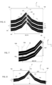
- the tread 10 comprises a plurality of patterns 13 which follow one another in the circumferential direction X. Each pattern 13 comprises a block 17 which extends, in the embodiment of the figure 1 , continuously from the first edge 14A of the tread 10 to the second edge 14B. This block 17 is delimited by oblique grooves 16A, 16B which are represented in gray on the figure 1 . In the tread, the oblique grooves 16A, 16B extend from the first edge 14A and from the second edge 14B to the central axis 12 of the tread.
- Block 17 also includes an incision 18 to promote the grip of the tire on snow-covered ground. In the tread, this incision 18 extends continuously from the first edge 14A to the second edge 14B. More particularly, the incision 18 here divides the block 17 into two parts of generally identical width.
- Each pattern 13 has a pitch P.
- This pitch P is determined as the distance between the centers of two adjacent oblique grooves framing a block 17. It will be noted that in the example of the figure 1 , the pitch P of the different tread patterns is identical.
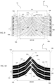
- FIG. 2 represents an imprint of the tread of the figure 1 .
- This imprint was made dynamically under conditions as described above.
- the recessed elements such as the oblique grooves 16A, 16B, the incisions 18 are represented in white.
- Blocks 17 are shown in black. From this imprint, it is possible to determine a slenderness E of the oblique grooves ( picture 3 ) and an SD incision density in blocks 17 ( figure 4 ).
- FIG. 3 There picture 3 represents part of the footprint of the figure 2 centered on an oblique groove 16A.
- this oblique groove 16A starts from the first edge 14A and stops at the level of the central axis 12. It is possible to determine a slenderness E of the oblique groove 16A in the central part of the tread. bearing, that is, the level of its inclination in this central part. As has already been specified, the central part is delimited in part by the third edge 15A.
- the projected length Lpx is measured between a first point A and a second point B.
- Point A is determined at the intersection between a median 19 of the oblique groove 16A and the third edge 15A.
- the median 19 of the oblique groove 16A separates said oblique groove 16A into two oblique half-grooves of the same width.
- Point B is determined at the intersection between the median 19 of the oblique groove 16A and the central axis 12 of the tread 10.
- the slenderness E is here between 0.85 and 1.5 and preferably between 0.87 and 1.1.
- block 17 extends continuously from the first edge 14A to the second edge 14B.
- the incision 18 also extends continuously between a third point C and a fourth point D.
- the third point C is determined at the intersection between the incision 18 and the first edge 14A.
- the fourth point D is determined at the intersection between the incision 18 and the second edge 14B.
- the incision density SD in block 17 is between 10 mm -1 and 42 mm -1 and preferably between 30 mm -1 and 40 mm -1 .
- the incision density in block 17 is 33.33 mm ⁇ 1 .
- a tire according to a second embodiment of the invention comprises a tread 10 and two sidewalls 11A, 11B framing said tread 10.
- the sidewalls 11A, 11B form the side parts of the tire.
- Each sidewall has at its end a bead intended to sit on a rim of a wheel.
- the sidewalls 11A, 11B delimit the tread 10 at a first edge 14A and a second edge 14B.
- the first edge 14A and the second edge 14B frame a central axis 12 of the tread 10.
- This first edge 14A and this second edge 14B determine a tread width W.
- This tread width is here greater than 140 mm.
- the tread 10 also comprises a central part centered on the central axis 12 and whose width corresponds to 80% of the width W of said tread 10. This central part is delimited by a third edge 15A and a fourth edge 15B.
- the tread 10 comprises a plurality of patterns 13 which follow one another in the circumferential direction X. Each pattern 13 comprises a set of blocks comprising here a first block 171 and a second block 172. These blocks 171, 172 extend respectively to from the first edge 14A and from the second edge 14B of the tread 10 as far as the central axis 12. These blocks 171, 172 are delimited by oblique grooves 16A, 16B.
- the oblique grooves 16A, 16B extend respectively from the first edge 14A and from the second edge 14B to the central axis 12. These oblique grooves 16A, 16B promote the evacuation of water out of the tread when driving on wet pavement.
- Each block 171, 172 respectively comprises a first incision 181 and a second incision 182 to promote the grip of the tire on snow-covered ground.
- each incision 181, 182 respectively extends from continuously from the first edge 14A or the second edge 14B to one end 21A, 21B of the block 171, 17
- each incision 181, 182 divides the associated block 171, 172 into two parts of generally identical width.
- Each pattern 13 has a pitch P.
- This pitch P is determined as the distance between the centers of two adjacent oblique grooves framing a block 171, 172. It will be noted that in the example of the figure 5 , the pitch P of the different tread patterns is identical.
- FIG 6 represents an imprint of the tread of the figure 5 .
- This imprint was made dynamically under conditions as described above.
- the recessed elements such as the oblique grooves 16A, 16B, the incisions 181, 182 are represented in white.
- Blocks 171, 172 are shown in black. From this imprint, it is possible to determine a slenderness E of the oblique grooves ( figure 7 ) and a density of SD incisions in blocks 171, 172 ( figure 8 ).
- FIG. 7 represents part of the footprint of the figure 6 centered on an oblique groove 16A.
- this oblique groove 16A starts from the first edge 14A and stops at the level of the central axis 12. It is possible to determine a slenderness E of the oblique groove 16A in the central part of the tread. bearing, that is, the level of its inclination in this central part. As has already been specified, the central part is delimited in part by the third edge 15A.
- the projected length Lpx is measured between a first point A and a second point B.
- Point A is determined at the intersection between a median 19 of the oblique groove 16A and the third edge 15A.
- the median 19 of the oblique groove 16A separates said oblique groove 16A into two oblique half-grooves of the same width.
- Point B is determined at the intersection between the median 19 of the oblique groove 16 and the central axis 12 of the tread 10.
- the slenderness E is here between 0.85 and 1.5, and preferably between 0.87 and 1.1.
- FIG 8 represents part of the footprint of the figure 6 centered on the first block 171 and the second block 172.
- the first block 171 extends from the first edge 14A to the central axis 12 of the tread and the second block 172 is extends from the second edge 14B to the central axis 12 of the tread.
- the first incision 181 of the first block 171 extends continuously between a third point C and the end 21A of the block 171.
- the third point C is determined at the intersection between the first incision 181 and the first edge 14A.
- the second incision 182 of the second block 172 extends continuously between a fourth point D and the end 21B of the block 172.
- the fourth point D is determined at the intersection between the second incision 182 and the second edge 14B.
- the incision density SD in the set of blocks comprising the first block 171 and the second block 172 is between 10 mm -1 and 42 mm -1 and preferably between 30 mm -1 and 40 mm -1 .
- a tire according to a third embodiment of the invention comprises a tread 10 and two sidewalls 11A, 11B framing said tread 10.
- the sidewalls 11A, 11B delimit the tread 10 at a first edge 14A and a second edge 14B.
- the first edge 14A and the second edge 14B frame a central axis 12 of the tread 10.
- This first edge 14A and this second edge 14B determine a tread width W.
- This tread width is here greater than 140 mm.
- the tread 10 also comprises a central part centered on the central axis 12 and whose width corresponds to 80% of the width W of said tread 10. This central part is delimited by a third edge 15A and a fourth edge 15B.
- the tread 10 comprises a plurality of patterns 13 which follow one another in the circumferential direction X.
- Each pattern 13 comprises a set of blocks comprising here 4 blocks, including a first block 171, a second block 172, a third block 173 and a fourth block 174.
- the first block 171 and the third block 173 are located on the same side with respect to the central axis 12.
- the second block 172 and the fourth block 174 are located on the same side with respect to the central axis 12 in opposition with respect to the first block 171 and the third block 173.
- the first block 171 and the third block 173 are separated by a first cutout 231.
- the second block 172 and the fourth block 174 are separated by a second cutout 232.
- the first cutout 231 and the second cutout 232 are here grooves which will decouple the blocks between them in order to facilitate the flattening of the tread during rolling.
- the first cutout 231 is an incision
- the two blocks 171, 173 form a single block.
- the second cutout 232 is an incision
- the two blocks 172, 174 form a single block.
- the first block 171 and the fourth block 174 respectively extend from the first edge 14A and from the second edge 14B of the tread 10 as far as the first cutout 231 and the second cutout 232.
- the second block 172 and the fourth block 174 respectively extend from the first cutout 231 and the second cutout 232 to the central axis 12.
- the blocks 171, 172, 173, 174 are delimited by oblique grooves 16A, 16B .
- the oblique grooves 16A, 16B extend respectively from the first edge 14A and from the second edge 14B to the central axis 12. These oblique grooves 16A, 16B promote the evacuation of water out of the tread when driving on wet pavement.
- Each block 171, 172, 173, 174 respectively comprises a first incision 181, a second incision 182, a third incision 183 and a fourth incision 184 to promote the grip of the tire on snow-covered ground.
- the first incision 181 and the fourth incision 184 respectively extend from the first edge 14A or from the second edge 14B to an end which does not here lead to the first cutout 231 or the second cutout 232.
- the second incision 182 and the third incision 183 respectively extend from the second cutout 232 and the first cutout 231 to the end 21B of the block 172 or to the end 21A of block 173.
- Each incision 181, 182, 183, 184 divides the associated blocks 171, 172, 173, 174 into two half-blocks of generally identical width.
- Each pattern 13 has a pitch P.
- This pitch P is determined as the distance between the centers of two adjacent oblique grooves framing a block 171, 172, 173, 174. It will be noted that in the example of figure 9 , the pitch P of the different tread patterns is identical.
- FIG 10 represents an imprint of the tread of the figure 9 .
- This imprint was made dynamically under conditions as described above.
- the recessed elements such as the oblique grooves 16A, 16B, the incisions 181, 182, 183, 184 are represented in white.
- Blocks 171, 172, 173, 174 are shown in black. From this imprint, it is possible to determine a slenderness E of the oblique grooves ( figure 11 ) and a density of SD incisions in blocks 171, 172, 173, 174 ( figure 12 ).
- FIG 11 represents part of the footprint of the figure 10 centered on an oblique groove 16A.
- this oblique groove 16A starts from the first edge 14A and stops at the level of the central axis 12. It is possible to determine a slenderness E of the oblique groove 16A in the central part of the tread. bearing, that is, the level of its inclination in this central part. As has already been specified, the central part is delimited in part by the third edge 15A.
- the projected length Lpx is measured between a first point A and a second point B.
- Point A is determined at the intersection between a median 19 of the oblique groove 16A and the third edge 15A.
- the median 19 of the oblique groove 16A separates said oblique groove 16A into two oblique half-grooves of the same width.
- Point B is determined at the intersection between the median 19 of the oblique groove 16 and the central axis 12 of the tread 10.
- the slenderness E is here between 0.85 and 1.5, and preferably between 0.87 and 1.1.
- FIG 12 represents part of the footprint of the figure 10 centered on the first block 171, the second block 172, the third block 173 and the fourth block 174.
- the first block 171 extends from the first edge 14A to the first cutout 231.
- the third block 173 extends from first cutout 231 to end 21A of block 173.
- Second block 172 extends from end 21B of block 172 to second cutout 232.
- the fourth block is extends from the second cutout 232 to the second edge 14B.
- the first incision 181 of the first block 171 extends between a third point C and an end close to the first cutout 231.
- the third point C is determined at the intersection between the first incision 181 and the first edge 14A.
- Third incision 183 extends from first cutout 231 to end 21A of block 173.
- Second incision 182 extends from end 21B of second block 172 to second cutout 232
- the fourth incision 184 extends from the second cutout 232 to the fourth point D.
- the fourth point D is determined at the intersection between the fourth incision 184 and the second edge 14B.
- the incision density SD in the set of blocks comprising the first block 171, the second block 172, the third block 173 and the fourth block 174 is between 10 mm -1 and 42 mm -1 and preferably between 30 mm -1 and 40 mm -1 .
- this tire comprises a tread 10 and two sidewalls 11A, 11B framing said tread 10.
- the sidewalls 11A, 11B delimit the tread 10 at a first edge 14A and a second edge 14B.
- the first edge 14A and the second edge 14B frame a central axis 12 of the tread 10. This first edge 14A and this second edge 14B thus determine a tread width W.
- This tread width is here greater than 140 mm.
- the tread 10 also comprises a central part centered on the central axis 12 and whose width corresponds to 80% of the width W of said tread 10. This central part is delimited by a third edge 15A and a fourth edge 15B.
- the tread 10 comprises a plurality of patterns 13 which follow one another in the circumferential direction X.
- Each pattern 13 comprises a set of blocks comprising here 6 blocks, including a first block 171, a second block 172, a third block 173, a fourth block 174, a fifth block 175, a sixth block 176.
- the first block 171, the third block 173 and the fifth block 175 are located on the same side with respect to the central axis 12.
- the second block 172, the fourth block 174 and the sixth block 176 are located on the same side with respect to the central axis 12 in opposition with respect to the first block 171, the third block 173 and the fifth block 175.
- the first block 171 and the third block 173 are separated by a first cutout 231.
- the second block 172 and the fourth block 174 are separated by a second cutout 232.
- the third block 173 and the fifth block 175 are separated by a third cutout 233.
- the fourth block 174 and the sixth block 176 are separated by a fourth cutout 234.
- the first cutout 231, the second cutout 232, the third cutout 233, the fourth cutout 234 are here grooves which will decouple the blocks from each other in order to facilitate the flattening of the tread during rolling.
- the first cutout 231, the second cutout 232, the third cutout 233 and the fourth cutout 234 are grooves.
- first block 171 and the sixth block 176 respectively extend from the first edge 14A and from the second edge 14B of the tread 10 as far as the first cutout 231 and the fourth cutout 234.
- the third block 173 and the fourth block 174 respectively extend from the first cutout 231 and the fourth cutout 234 to the third cutout 233 and the second cutout 232.
- the fifth block 175 and the second block 172 respectively extend to from the third cutout 233 and the second cutout 232 to the central axis 12.
- the blocks 171, 172, 173, 174, 175, 176 are delimited by oblique grooves 16A, 16B.
- the oblique grooves 16A, 16B extend respectively from the first edge 14A and from the second edge 14B to the central axis 12. As already indicated, these oblique grooves 16A, 16B promote the evacuation of water from the tread when driving on wet pavement.
- Each block 171, 172, 173, 174, 175, 176 respectively comprises a first incision 181, a second incision 182, a third incision 183, a fourth incision 184, a fifth incision 185 and a sixth incision 186 to promote adhesion of the tire on snowy ground.
- the first incision 181 and the sixth incision 186 respectively extend from the first edge 14A or from the second edge 14B to an end which does not here lead to the first cutout 231 or the fourth cutout 234.
- the third incision 183 and the fourth incision 184 respectively extend from the first cutout 231 and the fourth cutout 234 to the third cutout 233 and to the second cutout 232.
- the fifth incision 185 and the second incision 182 extend respectively from the third cutout 233 and the second cutout 232 to the end 21A of the block 175 and to the end 21B of the block 172.
- Each incision 181, 182, 183, 184, 185, 186 divides the associated blocks 171, 172, 173, 174, 175, 176 in two half-blocks of generally identical width.
- Each pattern 13 has a pitch P.
- This pitch P is determined as the distance between the centers of two adjacent oblique grooves framing a block 171, 172, 173, 174, 175, 176. It will be noted that in the example of figure 13 , the pitch P of the different tread patterns is identical.
- the figure 14 represents a portion of a tire tread footprint figure 13 .
- This imprint was made dynamically under conditions as described above.
- the recessed elements such as the oblique grooves 16A, 16B, the incisions 181, 182, 183, 184, 185, 186 are represented in white.
- Blocks 171, 172, 173, 174, 175, 176 are shown in black. From an imprint, it is possible to determine a slenderness E of the oblique grooves and a density of incisions SD in blocks 171, 172, 173, 174, 175, 176.
- the determination of the slenderness E is done in the same way as in the examples of figure 8 , 12 .
- This slenderness E is between 0.85 and 1.5 and preferably between 0.87 and 1.1.
- FIG 14 thus represents part of the tire tread footprint figure 13 centered on the first block 171, the second block 172, the third block 173, the fourth block 174, the fifth block 175 and the sixth block 176.
- the first block 171 extends from the first edge 14A up to the first cutout 231.
- the third block 173 extends from the first cutout 231 to the third cutout 233.
- the fifth block 175 extends from the third cutout 233 to the central axis 12.
- the second block 172 extends from centerline 12 to second cutout 232.
- Fourth block 174 extends from second cutout to fourth cutout 234.
- Sixth block 176 extends from fourth cutout 234 to the second edge 14B.
- the first incision 181 of the first block 171 extends between a third point C and an end close to the first cutout 231.
- the third point C is determined at the intersection between the first incision 181 and the first edge 14A.
- Third incision 183 extends from first cutout 231 to third cutout 233.
- Fifth incision 185 extends from third cutout 233 to end 21A of block 175.
- the second incision 182 extends from end 21B of second block 172 to second cutout 232.
- Fourth cutout 184 extends from second cutout 232 to fourth cutout 234.
- Sixth cutout 176 s extends from an end of this incision close to the fourth cutout 234 to the fourth point D.
- the fourth point D is determined at the intersection between the sixth incision 186 and the second edge 14B.
- the incision density SD in the set of blocks comprising the first block 171, the second block 172, the third block 173, the fourth block 174, the fifth block 175 and the sixth block 176 is between 10 mm -1 and 42 mm -1 and preferably between 30 mm -1 and 40 mm -1 .
- FIG. 15 represents part of a footprint of a tread according to a fifth embodiment of the invention.
- This footprint part is centered on the blocks of a pattern of this tread. More particularly, this footprint part comprises, as in the previous embodiment, a first block 171, a second block 172, a third block 173, a fourth block 174, a fifth block 175 and a sixth block 176.
- the first block 171 extends from first edge 14A to first cutout 231.
- Third block 173 extends from first cutout 231 to third cutout 233.
- Fifth block 175 extends from third cutout 233 to 'to the central axis 12.
- the second block 172 extends from the central axis 12 to the second cutout 232.
- the fourth block 174 extends from the second cutout to the fourth cutout 234.
- the sixth block 176 extends from fourth cutout 234 to second edge 14B.
- the different blocks 171, 172, 173, 174, 175, 176 comprise at least one incision.
- the first block 171 comprises a first incision 181
- the third block 173 comprises a third incision 183.
- the fifth block 175 for its part comprises three incisions: a fifth incision 185a, a fifth incision bis 185b and a fifth incision ter 185c.
- the second block 172 comprises three incisions: a second incision 182a, a second bis incision 182b and a second ter incision 182c.
- the fourth block 174 comprises a fourth incision 184 and the sixth block 176 comprises a sixth incision 186. More particularly, the first incision 181 of the first block 171 extends between a third point C and an end close to the first cutout 231. The third point C is determined at the intersection between the first incision 181 and the first edge 14A. The third incision 183 extends from the first cutout 231 to the third cutout 233.
- the fifth incision 185a, the fifth incision bis 185b and the fifth incision ter 185c extend globally in the axial direction from a first side wall of the fifth block 175 up to a second side wall of this fifth block 175.
- the second incision 182a, the second bis incision 182b and the second ter incision 182c extend globally in the axial direction from a first wall of the second block 172 to a second side wall of this second block 172.
- the fourth incision 184 extends from the second cutout 232 to the fourth cutout 234.
- the sixth incision 186 extends from an end of this incision close to the fourth cutout 234 to a fourth point D.
- the fourth point D is determined at the intersection between the sixth incision 186 and the second edge 14B.
- the incisions 181, 183, 184, 186 divide their associated block 171, 173, 174, 176 into two half-blocks of generally identical width.
- the portion of the tread pattern shown in figure 15 thus comprises at least two adjacent blocks, such as the couple of blocks comprising the third block 173 and the fifth block 175 or the couple of blocks comprising the second block 172 and the fourth block 174.
- These adjacent blocks have a different number of incisions and also a different arrangement of incisions.
- the incision density SD in the set of blocks comprising the first block 171, the second block 172, the third block 173, the fourth block 174, the fifth block 175 and the sixth block 176 is between 10 mm -1 and 42 mm -1 and preferably between 30 mm -1 and 40 mm -1 .
- THE figures 16, 17 and 18 illustrate three patterns of the same tread belonging to three different types of patterns.
- This first pattern thus illustrates a first pattern having a first step P1.
- This first pattern comprises a first block 171, a second block 172, a third block 173, a fourth block 174, a fifth block 175 and a sixth block 176.
- the first block 171 extends from the first edge 14A to a first cutout 231.
- the third block 173 extends from the first cutout 231 to the third cutout 233.
- the fifth block 175 extends from the third cutout 233 to the central axis 12.
- the second block 172 extends from the extends from the central axis 12 to the second cutout 232.
- the fourth block 174 extends from the second cutout 232 to the fourth cutout 234.
- the sixth block 176 extends from the fourth cutout 234 to the second edge 14B.
- the different blocks 171, 172, 173, 174, 175, 176 each include an incision.
- the first block 171 comprises a first incision 181 which extends between a third point C and an end close to the first cutout 231.
- the third point C is determined at the intersection between the first incision 181 and the first edge 14A .
- the third block 173 comprises a third incision 183 which extends between the first cutout 231 and the third cutout 233.
- the fifth block 175 comprises a fifth incision 185 which extends between the third cutout 233 and an end 21A of the fifth block 175
- the second block 172 includes a second incision 182 which extends between an end 21B of the second block 172 and a second cutout 232.
- the fourth block 174 includes a fourth incision 184 which extends between the second cutout 232 and the fourth cutout 234.
- the sixth block 176 includes a sixth incision 186 which extends between the fourth cutout 234 and a fourth point D.
- the fourth point D is determined at the intersection between the sixth incision 186 and the second edge 14B.
- the incisions 181, 182, 183, 184, 185, 186 divide their associated block 171, 172, 173, 174, 175, 176 into two half-blocks of generally identical width.
- FIG 17 illustrates a second pattern having a second pitch P2.
- this second pattern comprises a first block 171, a second block 172, a third block 173, a fourth block 174, a fifth block 175 and a sixth block 176.
- the different blocks 171, 172, 173, 174 , 175, 176 each include an incision 181, 182, 183, 184, 185, 186.
- the arrangement of the blocks 171, 172, 173, 174, 175, 176 and , 184, 185, 186 reference is made to the above description of the first pattern.
- FIG 18 illustrates a third pattern having a third step P3.
- this third pattern comprises a first block 171, a second block 172, a third block 173, a fourth block 174, a fifth block 175 and a sixth block 176.
- the different blocks 171, 172 , 173, 174, 175, 176 each include an incision 181, 182, 183, 184, 185, 186.
- incision 181, 182, 183, 184, 185, 186 For a more detailed description of the arrangement of blocks 171, 172, 173, 174, 175, 176 and , 182, 183, 184, 185, 186, reference is made to the above description of the first pattern or the second pattern.
- the tread comprises an arrangement of N1 pitch patterns P1, N2 pitch patterns P2 and N3 pitch patterns P3. It is thus possible to determine an average incision density SDmoy corresponding to the average of the incision densities SD1, SD2, SD3 of the patterns of steps P1, P2, P3 over the entire circumference of the tread.
- the pitch patterns P1, P2, P3 are arranged randomly on the tread in order to limit the emergence of noise from the tire when rolling.
- the arrangement between pitch patterns P1, P2 and P3 could be as follows: P1 P1 P2 P1 P2 P2 P2 P2 P1 P1 P2 P1 P1 P1 P2 P2 P3 P2 P2 P3 P2 P1 P2 P2 P1 P1 P1 P1 P2 P1 P1 P1 P1 P2 P1 P1 P1 P1 P2 P1 P1 P1 P2 P2 P3 P3 P3 P2 P2 P3 P3 P3 P3 P3 P3 P3 P3 P2 P2 P1 P2 P2 P3 P2 P1 P2 P2 P1 P2 P2 P1 P1 P2 P2 P1 P1 P1 P2 P3 P2 P1 P1 P1 P2 P3 P2 P1.
- Such an arrangement would then comprise 21 pitch patterns P1, 35 pitch patterns P2 and 13 pitch patterns P3.
- a pitch P is determined as the distance between the centers of two adjacent oblique grooves framing a block.
- these are measured in groups of patterns belonging to the same type of pattern, for example in groups of patterns P1 P1 P1, P2 P2 P2 and P3 P3 P3 .
- each block is formed from a rubber material.
- the composition of this rubber material has a glass transition temperature of between -40°C and -10°C, and preferably between -35°C and -15°C and a shear modulus measured at 60° C. between 0.5 MPa and 2 MPa, and preferably between 0.7 MPa and 1.5 MPa.
- the solution SBR of this preferred embodiment is a copolymer of styrene and butadiene prepared in solution. It has the characteristic of wearing a silanol function and an amine function.
- the silanol function of the SBR solution bearing a silanol function and an amine function can for example be introduced by hydrosilylation of the elastomer chain by a silane bearing an alkoxysilane group, followed by hydrolysis of the alkoxysilane function into silanol function.
- the silanol function of the SBR solution carrying a silanol function and an amine function can also be introduced by reaction of the living elastomer chains with a cyclic polysiloxane compound as described in EP 0 778 311 .
- the amine function of the SBR solution carrying a silanol function and an amine function can for example be introduced by initiating the polymerization with an initiator carrying such a function.
- An SBR solution bearing a silanol function and an amine function can also be prepared by reacting living elastomer chains with a compound bearing an alkoxysilane function and an amine function according to the procedure described in the patent application EP 2 285 852 , followed by hydrolysis of the alkoxysilane function to silanol function.
- the silanol function and the amine function are preferably located inside the chain of the SBR solution, outside the chain ends.
- the hydrolysis reaction of the alkoxysilane function carried by the SBR solution as a silanol function can be carried out according to the procedure described in the patent application EP 2 266 819 A1 or else by a step of stripping the solution containing the SBR solution.
- the amine function can be a primary, secondary or tertiary, preferably tertiary, amine.
- the blocks have a relatively low maximum radial height Hmax when new. This radial height is between 5.5 mm and 9 mm and preferably between 6 mm and 7.5 mm. This relatively low radial height could penalize grip on wet ground.
- the radial height is compensated by the strong slenderness of the tread and by the characteristics of the material used containing the SBR solution. This makes it possible to ensure good grip of the tire on wet ground over time.
- blind incisions which do not extend over the entire length of a block and which therefore do not join a cutout for all the ends of the cutouts.
- all the incisions of the blocks of the pattern open into a cutout.
- all the incisions of the blocks of the pattern are blind.
- the figure 18 has a number of oblique cutouts 231, 232, 233, 234 equal to four.
- the number of oblique cutouts on the tread is greater than four.
- the oblique cutouts 231, 232, 233, 234 have a depth identical to that of the oblique grooves 16A, 16B.
- the oblique cutouts have a depth less than that of the oblique grooves 16A, 16B.
- the patterns have an overall simple arrangement of the block(s).
- the patterns may have more complex arrangements.
- each pattern can comprise several adjacent blocks which follow one another in the circumferential direction. These adjacent blocks are delimited by secondary oblique grooves.
- These secondary oblique grooves may have a slenderness identical to the main oblique grooves 16A, 16B.
- the slenderness of the secondary oblique grooves is different from that of the main oblique grooves 16A, 16B.
Landscapes
- Chemical & Material Sciences (AREA)
- Engineering & Computer Science (AREA)
- Mechanical Engineering (AREA)
- Health & Medical Sciences (AREA)
- Chemical Kinetics & Catalysis (AREA)
- Medicinal Chemistry (AREA)
- Polymers & Plastics (AREA)
- Organic Chemistry (AREA)
- Oil, Petroleum & Natural Gas (AREA)
- Tires In General (AREA)
Claims (15)
- Reifen mit einem gerichteten Laufstreifen (10), wobei der Laufstreifen eine Mittelachse (12) und zwei Ränder (14A, 14B) umfasst, die die Mittelachse (12) einrahmen und eine Laufstreifenbreite W bestimmen, wobei die Laufstreifenbreite W 140 mm oder mehr beträgt, wobei der Laufstreifen (10) mehrere Muster (13) umfasst, die in Umfangsrichtung aufeinanderfolgen, wobei jedes Muster eine Teilung P aufweist, wobei die Muster (13) mehrere schräge Rillen (16A, 16B) begrenzen, wobei sich jede schräge Rille von einem der Ränder (14A, 14B) des Laufstreifens bis zur Mittelachse (12) erstreckt,- wobei in einem Mittelteil des Laufstreifens, der auf der Mittelachse (12) zentriert ist und eine Breite aufweist, die 80 % der Breite W des Laufstreifens entspricht, alle oder ein Teil der schrägen Rillen (16A, 16B) der mehreren schrägen Rillen einen Schlankheitsgrad E zwischen 0,85 und 1,5 und vorzugsweise zwischen 0,87 und 1,1 aufweisen, wobei der Schlankheitsgrad einem Verhältnis zwischen einer projizierten Länge Lpx der schrägen Rille in der Umfangsrichtung (X) und der Hälfte der Breite des Mittelteils des Laufstreifens (10) entspricht, sodass
 - alle oder ein Teil der Muster mindestens einen Einschnitt (18; 181, 182, 183, 184, 185, 186) umfassen, wobei eine Einschnittsdichte SD in allen oder einem Teil der Muster zwischen 10 mm-1 und 70 mm-1 beträgt, wobei die Einschnittsdichte SD dem Verhältnis zwischen der Summe der projizierten Länge(n) lpyi des Einschnitts (der Einschnitte) in einer axialen Richtung (Y) und dem Produkt aus der Teilung P des Musters und der Breite W des Laufstreifens entspricht, wobei das Ganze mit 1.000 multipliziert wird, sodass
- Reifen nach Anspruch 1, wobei der Laufstreifen verschiedene Musterarten Mj umfasst, wobei j größer oder gleich 2 ist, wobei die Muster, die zu einer gleichen Musterart gehören, eine gleiche Teilung aufweisen, wobei die Teilung zwischen Mustern, die zu zwei verschiedenen Musterarten gehören, unterschiedlich ist, und wobei die mittlere Einschnittsdichte SDmoy zwischen 10 mm-1 und 70 mm-1 beträgt, wobei die mittlere Einschnittsdichte SDmoy dem Mittelwert der Einschnittsdichten SDj der Muster der verschiedenen Musterarten Mj über den gesamten Umfang des Laufstreifens entspricht, wobei die mittlere Einschnittsdichte SDmoy in Abhängigkeit von der Musteranzahl Nj pro Musterart Mj und von der Teilung Pj der zu einer Musterart Mj gehörenden Muster über den Umfang des Laufstreifens gewichtet ist, sodass

- Reifen nach Anspruch 1 oder Anspruch 2, wobei die Einschnittsdichte SD oder die mittlere Einschnittsdichte SDmoy größer als 25 mm-1 und/oder kleiner als 50 mm-1 ist.
- Reifen nach einem der Ansprüche 1 bis 3, wobei die Einschnittsdichte SD oder die mittlere Einschnittsdichte SDmoy zwischen 30 mm-1 und 40 mm-1 beträgt.
- Reifen nach einem der Ansprüche 1 bis 4, wobei jedes Muster (13) eine Blockanordnung umfasst, die mindestens einen Block (17; 171, 172, 173, 174, 175, 176) aufweist, wobei der Block eine maximale radiale Höhe Hmax im Neuzustand zwischen 5,5 mm und 9 mm und vorzugsweise zwischen 6 mm und 7,5 mm aufweist.
- Reifen nach Anspruch 5, wobei jedes Muster mindestens zwei benachbarte Blöcke (171, 173; 173, 175; 175, 172; 172, 174; 174, 176) umfasst, wobei die Anzahl der Einschnitte in jedem Block einen Einschnitt oder mehr beträgt, wobei die Anzahl der Einschnitte und/oder die Anordnung der Einschnitte zwischen den beiden benachbarten Blöcken unterschiedlich ist.
- Reifen nach einem der Ansprüche 5 oder 6, wobei der oder die Blöcke (17; 171, 172, 173, 174, 175, 176) aus einem kautschukartigen Material gebildet sind, wobei die Zusammensetzung des kautschukartigen Materials eine Glasübergangstemperatur Tg zwischen -40°C und -10°C und vorzugsweise zwischen -35°C und -15°C und einen komplexen dynamischen Schubmodul G*, gemessen bei 60°C, zwischen 0,5 MPa und 2 MPa, und vorzugsweise zwischen 0,7 MPa und 1,5 MPa aufweist.
- Reifen nach einem der Ansprüche 5 bis 7, wobei die Zusammensetzung des Blocks eine elastomere Mischung umfasst, wobei die elastomere Mischung ein modifiziertes Dienelastomer umfasst, das mindestens eine funktionelle Gruppe mit einem Siliciumatom umfasst, wobei sich letzteres innerhalb der Hauptkette des Elastomers einschließlich der Kettenenden befindet.
- Reifen nach Anspruch 8, wobei das modifizierte Dienelastomer, das eine funktionelle Gruppe mit einem Siliciumatom umfasst, ein modifiziertes Elastomer ist, das mindestens eine Silanolfunktion umfasst, die sich an einem Ende der Hauptkette des Elastomers befindet.
- Reifen nach Anspruch 8, wobei das modifizierte Dienelastomer, das eine funktionelle Gruppe mit einem Siliciumatom umfasst, ein modifiziertes Elastomer ist, das innerhalb seiner Struktur mindestens eine Alkoxysilangruppe, die über das Siliciumatom an das Elastomer gebunden ist, und mindestens eine Funktion mit einem Stickstoffatom umfasst.
- Reifen nach Anspruch 10, wobei das modifizierte Dienelastomer überwiegend in der Kettenmitte durch eine Alkoxysilangruppe funktionalisiert ist, die über das Siliciumatom an die beiden Zweige des modifizierten Dienelastomers gebunden ist.
- Reifen nach einem der Ansprüche 10 oder 11, wobei das modifizierte Dienelastomer mindestens zwei, vorzugsweise alle der folgenden Merkmale aufweist:- die Funktion mit einem Stickstoffatom ist ein tertiäres Amin, insbesondere eine Diethylamino- oder Dimethylaminogruppe,- die Funktion mit einem Stickstoffatom wird durch die Alkoxysilangruppe über eine Spacergruppe getragen, die als aliphatischer C1-C10-Kohlenwasserstoffrest definiert ist, besonders vorzugsweise der lineare C2- oder C3-Kohlenwasserstoffrest,- die Alkoxysilangruppe ist ein Methoxysilan oder ein Ethoxysilan, das gegebenenfalls teilweise oder vollständig zu Silanol hydrolysiert ist.
- Reifen nach einem der Ansprüche 8 bis 12, wobei das modifizierte Dienelastomer ein Styrol-Butadien-Copolymer ist.
- Reifen nach einem der Ansprüche 8 bis 13, wobei das modifizierte Dienelastomer eine Glasübergangstemperatur in einem Bereich von -105°C bis -70°C aufweist.
- Reifen nach einem der Ansprüche 1 bis 14, wobei der Reifen eine 3PMSF-Winterzertifizierung aufweist, wobei die Zertifizierung auf einer Flanke des Reifens angegeben ist.
Applications Claiming Priority (2)
| Application Number | Priority Date | Filing Date | Title |
|---|---|---|---|
| FR1908517A FR3099084B1 (fr) | 2019-07-26 | 2019-07-26 | Pneumatique comportant une bande de roulement |
| PCT/FR2020/051372 WO2021019174A1 (fr) | 2019-07-26 | 2020-07-27 | Pneumatique comportant une bande de roulement |
Publications (2)
| Publication Number | Publication Date |
|---|---|
| EP4003761A1 EP4003761A1 (de) | 2022-06-01 |
| EP4003761B1 true EP4003761B1 (de) | 2023-07-05 |
Family
ID=68733285
Family Applications (1)
| Application Number | Title | Priority Date | Filing Date |
|---|---|---|---|
| EP20757643.0A Active EP4003761B1 (de) | 2019-07-26 | 2020-07-27 | Reifen mit lauffläche |
Country Status (5)
| Country | Link |
|---|---|
| US (1) | US20220274444A1 (de) |
| EP (1) | EP4003761B1 (de) |
| CN (1) | CN114174079B (de) |
| FR (1) | FR3099084B1 (de) |
| WO (1) | WO2021019174A1 (de) |
Families Citing this family (9)
| Publication number | Priority date | Publication date | Assignee | Title |
|---|---|---|---|---|
| EP4054860B1 (de) | 2019-11-06 | 2025-05-28 | Compagnie Generale Des Etablissements Michelin | Reifen mit einer lauffläche |
| JP7815745B2 (ja) * | 2021-12-21 | 2026-02-18 | 住友ゴム工業株式会社 | タイヤ |
| DE102023200378A1 (de) | 2023-01-18 | 2024-07-18 | Continental Reifen Deutschland Gmbh | Laufstreifen für einen Fahrzeugreifen |
| FR3148541A1 (fr) * | 2023-05-12 | 2024-11-15 | Compagnie Generale Des Etablissements Michelin | Pneumatique à bande de roulement molle et à sculpture rigide |
| DE102024107320A1 (de) * | 2024-03-14 | 2025-09-18 | Continental Reifen Deutschland Gmbh | Fahrzeugreifen |
| FR3161387A1 (fr) * | 2024-04-18 | 2025-10-24 | Compagnie Generale Des Etablissements Michelin | Pneumatique comprenant un sous-creux réduit et une bande de roulement silencieuse |
| FR3161386A1 (fr) * | 2024-04-18 | 2025-10-24 | Compagnie Generale Des Etablissements Michelin | Pneumatique à bonne adhérence sur sol mouillé et à grande longévité |
| FR3165689A1 (fr) * | 2024-08-26 | 2026-02-27 | Compagnie Generale Des Etablissements Michelin | Pneumatique à performances durables améliorées |
| FR3165690A1 (fr) * | 2024-08-26 | 2026-02-27 | Compagnie Generale Des Etablissements Michelin | Pneumatique à performances durables maximisées |
Family Cites Families (25)
| Publication number | Priority date | Publication date | Assignee | Title |
|---|---|---|---|---|
| JPH0220407A (ja) * | 1988-07-09 | 1990-01-24 | Sumitomo Rubber Ind Ltd | 重車両用ラジアルタイヤ |
| IT1248635B (it) | 1990-01-10 | 1995-01-21 | Uniroyal Englebert Gmbh | Pneumatico radiale per veicoli,con estremita'degli_elementi del profi lo,nella zona cinturata del battistrada,sviluppati a forma di forcella |
| US5327952A (en) * | 1991-03-08 | 1994-07-12 | The Goodyear Tire & Rubber Company | Pneumatic tire having improved wet traction |
| JP3127172B2 (ja) * | 1992-05-14 | 2001-01-22 | 株式会社ブリヂストン | 空気入りタイヤ |
| AT400424B (de) * | 1993-01-28 | 1995-12-27 | Semperit Ag | Fahrzeugreifen |
| FR2740778A1 (fr) | 1995-11-07 | 1997-05-09 | Michelin & Cie | Composition de caoutchouc a base de silice et de polymere dienique fonctionalise ayant une fonction silanol terminale |
| JP4400817B2 (ja) * | 2003-11-17 | 2010-01-20 | 東洋ゴム工業株式会社 | 空気入りラジアルタイヤ |
| US9623705B2 (en) | 2008-03-10 | 2017-04-18 | Bridgestone Corporation | Method for producing modified conjugated diene polymer/copolymer, modified conjugated diene polymer/copolymer, and rubber composition and tire using the same |
| FR2930554B1 (fr) | 2008-04-29 | 2012-08-17 | Michelin Soc Tech | Melange elastomerique comprenant majoritairement un elastomere dienique couple par un groupe amino-alcoxysilane, composition de caoutchouc le comprenant et leurs procedes d'obtention. |
| FR2951178B1 (fr) | 2009-10-08 | 2012-08-17 | Michelin Soc Tech | Elastomere dienique fonctionnalise et composition de caoutchouc le contenant. |
| JP5545854B2 (ja) * | 2010-08-23 | 2014-07-09 | 株式会社ブリヂストン | タイヤ |
| FR2964601B1 (fr) * | 2010-09-10 | 2012-09-07 | Michelin Soc Tech | Bande de roulement pour pneumatique |
| US8757229B2 (en) * | 2010-10-29 | 2014-06-24 | The Goodyear Tire & Rubber Company | Winter tire center tread pattern |
| DE102010061086A1 (de) * | 2010-12-07 | 2012-06-14 | Continental Reifen Deutschland Gmbh | Fahrzeugluftreifen |
| JP5909045B2 (ja) * | 2011-03-02 | 2016-04-26 | 株式会社ブリヂストン | 空気入りタイヤ |
| FR3009559A1 (fr) | 2013-08-08 | 2015-02-13 | Michelin & Cie | Elastomere dienique modifie, son procede de synthese et composition de caoutchouc le comprenant |
| FR3009558B1 (fr) | 2013-08-09 | 2015-09-04 | Michelin & Cie | Elastomere dienique couple possedant une fonction silanol en milieu de chaine et fonctionnalise amine en extremite de chaine et composition de caoutchouc le comprenant |
| FR3009557B1 (fr) | 2013-08-09 | 2015-09-11 | Michelin & Cie | Elastomere dienique modifie comprenant un elastomere dienique couple par un compose aminoalcoxysilane et fonctionnalise amine en extremite de chaine et composition de caoutchouc le comprenant |
| JP2015051753A (ja) * | 2013-09-09 | 2015-03-19 | 横浜ゴム株式会社 | 空気入りタイヤ |
| JP5852634B2 (ja) * | 2013-12-20 | 2016-02-03 | 住友ゴム工業株式会社 | 空気入りタイヤ |
| DE102014213266A1 (de) * | 2014-07-09 | 2016-01-14 | Continental Reifen Deutschland Gmbh | Fahrzeugluftreifen |
| FR3033142B1 (fr) * | 2015-02-27 | 2017-02-24 | Michelin & Cie | Pneumatique avec bande de roulement directionnelle comportant une alternance de blocs et rainures incurves |
| DE102015224291A1 (de) * | 2015-12-04 | 2017-06-08 | Continental Reifen Deutschland Gmbh | Fahrzeugluftreifen |
| DE102017203225A1 (de) * | 2017-02-28 | 2018-08-30 | Continental Reifen Deutschland Gmbh | Fahrzeugluftreifen |
| DE102017203221A1 (de) * | 2017-02-28 | 2018-08-30 | Continental Reifen Deutschland Gmbh | Fahrzeugluftreifen |
-
2019
- 2019-07-26 FR FR1908517A patent/FR3099084B1/fr active Active
-
2020
- 2020-07-27 US US17/630,192 patent/US20220274444A1/en active Pending
- 2020-07-27 EP EP20757643.0A patent/EP4003761B1/de active Active
- 2020-07-27 CN CN202080051270.9A patent/CN114174079B/zh active Active
- 2020-07-27 WO PCT/FR2020/051372 patent/WO2021019174A1/fr not_active Ceased
Also Published As
| Publication number | Publication date |
|---|---|
| FR3099084B1 (fr) | 2021-06-25 |
| CN114174079B (zh) | 2023-10-13 |
| FR3099084A1 (fr) | 2021-01-29 |
| EP4003761A1 (de) | 2022-06-01 |
| US20220274444A1 (en) | 2022-09-01 |
| CN114174079A (zh) | 2022-03-11 |
| WO2021019174A1 (fr) | 2021-02-04 |
Similar Documents
| Publication | Publication Date | Title |
|---|---|---|
| EP4003761B1 (de) | Reifen mit lauffläche | |
| EP4003757B1 (de) | Reifen mit lauffläche | |
| EP4054862B1 (de) | Reifen mit lauffläche | |
| EP4054860B1 (de) | Reifen mit einer lauffläche | |
| EP4054858B1 (de) | Reifen mit einer lauffläche | |
| EP4171971B1 (de) | Reifen mit einer lauffläche, die für die griffigkeit auf nassboden im abgenutzen zustand optimiert ist | |
| EP4054863B1 (de) | Reifen mit einer lauffläche | |
| EP4126566B1 (de) | Reifen mit einer lauffläche mit optimierter griffigkeit auf schneebedecktem grund | |
| EP4054859B1 (de) | Reifen mit lauffläche | |
| EP4054864B1 (de) | Reifen mit einer lauffläche | |
| EP4126565B1 (de) | Reifen mit optimierter lauffläche in bezug auf die haftung auf trockenem boden | |
| EP4237261A1 (de) | Reifen mit einer lauffläche mit verstärkten umfangsrillen | |
| WO2025219093A1 (fr) | Pneumatique à bonne adhérence sur sol mouillé et à grande longévité | |
| WO2025082947A1 (fr) | Pneumatique comportant une bande de roulement recreusable | |
| WO2025219092A1 (fr) | Pneumatique comprenant un sous-creux réduit et une bande de roulement silencieuse | |
| FR3159557A1 (fr) | Pneumatique comprenant une bande de roulement complexe à interface endurante | |
| FR3159556A1 (fr) | Pneumatique comprenant une bande de roulement complexe résistante à l’usure |
Legal Events
| Date | Code | Title | Description |
|---|---|---|---|
| STAA | Information on the status of an ep patent application or granted ep patent |
Free format text: STATUS: UNKNOWN |
|
| STAA | Information on the status of an ep patent application or granted ep patent |
Free format text: STATUS: THE INTERNATIONAL PUBLICATION HAS BEEN MADE |
|
| PUAI | Public reference made under article 153(3) epc to a published international application that has entered the european phase |
Free format text: ORIGINAL CODE: 0009012 |
|
| STAA | Information on the status of an ep patent application or granted ep patent |
Free format text: STATUS: REQUEST FOR EXAMINATION WAS MADE |
|
| 17P | Request for examination filed |
Effective date: 20220228 |
|
| AK | Designated contracting states |
Kind code of ref document: A1 Designated state(s): AL AT BE BG CH CY CZ DE DK EE ES FI FR GB GR HR HU IE IS IT LI LT LU LV MC MK MT NL NO PL PT RO RS SE SI SK SM TR |
|
| DAV | Request for validation of the european patent (deleted) | ||
| DAX | Request for extension of the european patent (deleted) | ||
| GRAP | Despatch of communication of intention to grant a patent |
Free format text: ORIGINAL CODE: EPIDOSNIGR1 |
|
| STAA | Information on the status of an ep patent application or granted ep patent |
Free format text: STATUS: GRANT OF PATENT IS INTENDED |
|
| INTG | Intention to grant announced |
Effective date: 20230126 |
|
| GRAS | Grant fee paid |
Free format text: ORIGINAL CODE: EPIDOSNIGR3 |
|
| GRAA | (expected) grant |
Free format text: ORIGINAL CODE: 0009210 |
|
| STAA | Information on the status of an ep patent application or granted ep patent |
Free format text: STATUS: THE PATENT HAS BEEN GRANTED |
|
| AK | Designated contracting states |
Kind code of ref document: B1 Designated state(s): AL AT BE BG CH CY CZ DE DK EE ES FI FR GB GR HR HU IE IS IT LI LT LU LV MC MK MT NL NO PL PT RO RS SE SI SK SM TR |
|
| REG | Reference to a national code |
Ref country code: CH Ref legal event code: EP |
|
| REG | Reference to a national code |
Ref country code: AT Ref legal event code: REF Ref document number: 1584527 Country of ref document: AT Kind code of ref document: T Effective date: 20230715 |
|
| REG | Reference to a national code |
Ref country code: DE Ref legal event code: R096 Ref document number: 602020013398 Country of ref document: DE |
|
| REG | Reference to a national code |
Ref country code: IE Ref legal event code: FG4D Free format text: LANGUAGE OF EP DOCUMENT: FRENCH |
|
| REG | Reference to a national code |
Ref country code: LT Ref legal event code: MG9D |
|
| REG | Reference to a national code |
Ref country code: NL Ref legal event code: MP Effective date: 20230705 |
|
| REG | Reference to a national code |
Ref country code: AT Ref legal event code: MK05 Ref document number: 1584527 Country of ref document: AT Kind code of ref document: T Effective date: 20230705 |
|
| PG25 | Lapsed in a contracting state [announced via postgrant information from national office to epo] |
Ref country code: NL Free format text: LAPSE BECAUSE OF FAILURE TO SUBMIT A TRANSLATION OF THE DESCRIPTION OR TO PAY THE FEE WITHIN THE PRESCRIBED TIME-LIMIT Effective date: 20230705 |
|
| PG25 | Lapsed in a contracting state [announced via postgrant information from national office to epo] |
Ref country code: GR Free format text: LAPSE BECAUSE OF FAILURE TO SUBMIT A TRANSLATION OF THE DESCRIPTION OR TO PAY THE FEE WITHIN THE PRESCRIBED TIME-LIMIT Effective date: 20231006 |
|
| PG25 | Lapsed in a contracting state [announced via postgrant information from national office to epo] |
Ref country code: ES Free format text: LAPSE BECAUSE OF FAILURE TO SUBMIT A TRANSLATION OF THE DESCRIPTION OR TO PAY THE FEE WITHIN THE PRESCRIBED TIME-LIMIT Effective date: 20230705 |
|
| PG25 | Lapsed in a contracting state [announced via postgrant information from national office to epo] |
Ref country code: IS Free format text: LAPSE BECAUSE OF FAILURE TO SUBMIT A TRANSLATION OF THE DESCRIPTION OR TO PAY THE FEE WITHIN THE PRESCRIBED TIME-LIMIT Effective date: 20231105 |
|
| PG25 | Lapsed in a contracting state [announced via postgrant information from national office to epo] |
Ref country code: SE Free format text: LAPSE BECAUSE OF FAILURE TO SUBMIT A TRANSLATION OF THE DESCRIPTION OR TO PAY THE FEE WITHIN THE PRESCRIBED TIME-LIMIT Effective date: 20230705 Ref country code: RS Free format text: LAPSE BECAUSE OF FAILURE TO SUBMIT A TRANSLATION OF THE DESCRIPTION OR TO PAY THE FEE WITHIN THE PRESCRIBED TIME-LIMIT Effective date: 20230705 Ref country code: PT Free format text: LAPSE BECAUSE OF FAILURE TO SUBMIT A TRANSLATION OF THE DESCRIPTION OR TO PAY THE FEE WITHIN THE PRESCRIBED TIME-LIMIT Effective date: 20231106 Ref country code: NO Free format text: LAPSE BECAUSE OF FAILURE TO SUBMIT A TRANSLATION OF THE DESCRIPTION OR TO PAY THE FEE WITHIN THE PRESCRIBED TIME-LIMIT Effective date: 20231005 Ref country code: LV Free format text: LAPSE BECAUSE OF FAILURE TO SUBMIT A TRANSLATION OF THE DESCRIPTION OR TO PAY THE FEE WITHIN THE PRESCRIBED TIME-LIMIT Effective date: 20230705 Ref country code: LT Free format text: LAPSE BECAUSE OF FAILURE TO SUBMIT A TRANSLATION OF THE DESCRIPTION OR TO PAY THE FEE WITHIN THE PRESCRIBED TIME-LIMIT Effective date: 20230705 Ref country code: IS Free format text: LAPSE BECAUSE OF FAILURE TO SUBMIT A TRANSLATION OF THE DESCRIPTION OR TO PAY THE FEE WITHIN THE PRESCRIBED TIME-LIMIT Effective date: 20231105 Ref country code: HR Free format text: LAPSE BECAUSE OF FAILURE TO SUBMIT A TRANSLATION OF THE DESCRIPTION OR TO PAY THE FEE WITHIN THE PRESCRIBED TIME-LIMIT Effective date: 20230705 Ref country code: GR Free format text: LAPSE BECAUSE OF FAILURE TO SUBMIT A TRANSLATION OF THE DESCRIPTION OR TO PAY THE FEE WITHIN THE PRESCRIBED TIME-LIMIT Effective date: 20231006 Ref country code: FI Free format text: LAPSE BECAUSE OF FAILURE TO SUBMIT A TRANSLATION OF THE DESCRIPTION OR TO PAY THE FEE WITHIN THE PRESCRIBED TIME-LIMIT Effective date: 20230705 Ref country code: ES Free format text: LAPSE BECAUSE OF FAILURE TO SUBMIT A TRANSLATION OF THE DESCRIPTION OR TO PAY THE FEE WITHIN THE PRESCRIBED TIME-LIMIT Effective date: 20230705 Ref country code: AT Free format text: LAPSE BECAUSE OF FAILURE TO SUBMIT A TRANSLATION OF THE DESCRIPTION OR TO PAY THE FEE WITHIN THE PRESCRIBED TIME-LIMIT Effective date: 20230705 |
|
| PG25 | Lapsed in a contracting state [announced via postgrant information from national office to epo] |
Ref country code: PL Free format text: LAPSE BECAUSE OF FAILURE TO SUBMIT A TRANSLATION OF THE DESCRIPTION OR TO PAY THE FEE WITHIN THE PRESCRIBED TIME-LIMIT Effective date: 20230705 |
|
| REG | Reference to a national code |
Ref country code: CH Ref legal event code: PL |
|
| REG | Reference to a national code |
Ref country code: BE Ref legal event code: MM Effective date: 20230731 |
|
| PG25 | Lapsed in a contracting state [announced via postgrant information from national office to epo] |
Ref country code: LU Free format text: LAPSE BECAUSE OF NON-PAYMENT OF DUE FEES Effective date: 20230727 |
|
| PG25 | Lapsed in a contracting state [announced via postgrant information from national office to epo] |
Ref country code: LU Free format text: LAPSE BECAUSE OF NON-PAYMENT OF DUE FEES Effective date: 20230727 |
|
| REG | Reference to a national code |
Ref country code: DE Ref legal event code: R097 Ref document number: 602020013398 Country of ref document: DE |
|
| REG | Reference to a national code |
Ref country code: IE Ref legal event code: MM4A |
|
| PG25 | Lapsed in a contracting state [announced via postgrant information from national office to epo] |
Ref country code: SM Free format text: LAPSE BECAUSE OF FAILURE TO SUBMIT A TRANSLATION OF THE DESCRIPTION OR TO PAY THE FEE WITHIN THE PRESCRIBED TIME-LIMIT Effective date: 20230705 Ref country code: RO Free format text: LAPSE BECAUSE OF FAILURE TO SUBMIT A TRANSLATION OF THE DESCRIPTION OR TO PAY THE FEE WITHIN THE PRESCRIBED TIME-LIMIT Effective date: 20230705 Ref country code: EE Free format text: LAPSE BECAUSE OF FAILURE TO SUBMIT A TRANSLATION OF THE DESCRIPTION OR TO PAY THE FEE WITHIN THE PRESCRIBED TIME-LIMIT Effective date: 20230705 Ref country code: DK Free format text: LAPSE BECAUSE OF FAILURE TO SUBMIT A TRANSLATION OF THE DESCRIPTION OR TO PAY THE FEE WITHIN THE PRESCRIBED TIME-LIMIT Effective date: 20230705 Ref country code: CZ Free format text: LAPSE BECAUSE OF FAILURE TO SUBMIT A TRANSLATION OF THE DESCRIPTION OR TO PAY THE FEE WITHIN THE PRESCRIBED TIME-LIMIT Effective date: 20230705 Ref country code: SK Free format text: LAPSE BECAUSE OF FAILURE TO SUBMIT A TRANSLATION OF THE DESCRIPTION OR TO PAY THE FEE WITHIN THE PRESCRIBED TIME-LIMIT Effective date: 20230705 Ref country code: CH Free format text: LAPSE BECAUSE OF NON-PAYMENT OF DUE FEES Effective date: 20230731 Ref country code: MC Free format text: LAPSE BECAUSE OF FAILURE TO SUBMIT A TRANSLATION OF THE DESCRIPTION OR TO PAY THE FEE WITHIN THE PRESCRIBED TIME-LIMIT Effective date: 20230705 |
|
| PLBE | No opposition filed within time limit |
Free format text: ORIGINAL CODE: 0009261 |
|
| STAA | Information on the status of an ep patent application or granted ep patent |
Free format text: STATUS: NO OPPOSITION FILED WITHIN TIME LIMIT |
|
| PG25 | Lapsed in a contracting state [announced via postgrant information from national office to epo] |
Ref country code: IT Free format text: LAPSE BECAUSE OF FAILURE TO SUBMIT A TRANSLATION OF THE DESCRIPTION OR TO PAY THE FEE WITHIN THE PRESCRIBED TIME-LIMIT Effective date: 20230705 Ref country code: BE Free format text: LAPSE BECAUSE OF NON-PAYMENT OF DUE FEES Effective date: 20230731 |
|
| 26N | No opposition filed |
Effective date: 20240408 |
|
| PG25 | Lapsed in a contracting state [announced via postgrant information from national office to epo] |
Ref country code: IE Free format text: LAPSE BECAUSE OF NON-PAYMENT OF DUE FEES Effective date: 20230727 |
|
| PG25 | Lapsed in a contracting state [announced via postgrant information from national office to epo] |
Ref country code: IE Free format text: LAPSE BECAUSE OF NON-PAYMENT OF DUE FEES Effective date: 20230727 Ref country code: SI Free format text: LAPSE BECAUSE OF FAILURE TO SUBMIT A TRANSLATION OF THE DESCRIPTION OR TO PAY THE FEE WITHIN THE PRESCRIBED TIME-LIMIT Effective date: 20230705 |
|
| PG25 | Lapsed in a contracting state [announced via postgrant information from national office to epo] |
Ref country code: BG Free format text: LAPSE BECAUSE OF FAILURE TO SUBMIT A TRANSLATION OF THE DESCRIPTION OR TO PAY THE FEE WITHIN THE PRESCRIBED TIME-LIMIT Effective date: 20230705 |
|
| PG25 | Lapsed in a contracting state [announced via postgrant information from national office to epo] |
Ref country code: BG Free format text: LAPSE BECAUSE OF FAILURE TO SUBMIT A TRANSLATION OF THE DESCRIPTION OR TO PAY THE FEE WITHIN THE PRESCRIBED TIME-LIMIT Effective date: 20230705 |
|
| GBPC | Gb: european patent ceased through non-payment of renewal fee |
Effective date: 20240727 |
|
| PG25 | Lapsed in a contracting state [announced via postgrant information from national office to epo] |
Ref country code: GB Free format text: LAPSE BECAUSE OF NON-PAYMENT OF DUE FEES Effective date: 20240727 |
|
| PG25 | Lapsed in a contracting state [announced via postgrant information from national office to epo] |
Ref country code: CY Free format text: LAPSE BECAUSE OF FAILURE TO SUBMIT A TRANSLATION OF THE DESCRIPTION OR TO PAY THE FEE WITHIN THE PRESCRIBED TIME-LIMIT; INVALID AB INITIO Effective date: 20200727 |
|
| PG25 | Lapsed in a contracting state [announced via postgrant information from national office to epo] |
Ref country code: HU Free format text: LAPSE BECAUSE OF FAILURE TO SUBMIT A TRANSLATION OF THE DESCRIPTION OR TO PAY THE FEE WITHIN THE PRESCRIBED TIME-LIMIT; INVALID AB INITIO Effective date: 20200727 |
|
| PGFP | Annual fee paid to national office [announced via postgrant information from national office to epo] |
Ref country code: DE Payment date: 20250722 Year of fee payment: 6 |
|
| PGFP | Annual fee paid to national office [announced via postgrant information from national office to epo] |
Ref country code: FR Payment date: 20250725 Year of fee payment: 6 |
|
| PG25 | Lapsed in a contracting state [announced via postgrant information from national office to epo] |
Ref country code: TR Free format text: LAPSE BECAUSE OF FAILURE TO SUBMIT A TRANSLATION OF THE DESCRIPTION OR TO PAY THE FEE WITHIN THE PRESCRIBED TIME-LIMIT Effective date: 20230705 |