EP4003769B1 - Vorrichtung zur regelung eines luftstroms eines kraftfahrzeuges - Google Patents
Vorrichtung zur regelung eines luftstroms eines kraftfahrzeuges Download PDFInfo
- Publication number
- EP4003769B1 EP4003769B1 EP20742351.8A EP20742351A EP4003769B1 EP 4003769 B1 EP4003769 B1 EP 4003769B1 EP 20742351 A EP20742351 A EP 20742351A EP 4003769 B1 EP4003769 B1 EP 4003769B1
- Authority
- EP
- European Patent Office
- Prior art keywords
- curtain
- belt
- winding
- curtains
- air flow
- Prior art date
- Legal status (The legal status is an assumption and is not a legal conclusion. Google has not performed a legal analysis and makes no representation as to the accuracy of the status listed.)
- Active
Links
Images




Classifications
-
- B—PERFORMING OPERATIONS; TRANSPORTING
- B60—VEHICLES IN GENERAL
- B60K—ARRANGEMENT OR MOUNTING OF PROPULSION UNITS OR OF TRANSMISSIONS IN VEHICLES; ARRANGEMENT OR MOUNTING OF PLURAL DIVERSE PRIME-MOVERS IN VEHICLES; AUXILIARY DRIVES FOR VEHICLES; INSTRUMENTATION OR DASHBOARDS FOR VEHICLES; ARRANGEMENTS IN CONNECTION WITH COOLING, AIR INTAKE, GAS EXHAUST OR FUEL SUPPLY OF PROPULSION UNITS IN VEHICLES
- B60K11/00—Arrangement in connection with cooling of propulsion units
- B60K11/08—Air inlets for cooling; Shutters or blinds therefor
- B60K11/085—Air inlets for cooling; Shutters or blinds therefor with adjustable shutters or blinds
-
- F—MECHANICAL ENGINEERING; LIGHTING; HEATING; WEAPONS; BLASTING
- F01—MACHINES OR ENGINES IN GENERAL; ENGINE PLANTS IN GENERAL; STEAM ENGINES
- F01P—COOLING OF MACHINES OR ENGINES IN GENERAL; COOLING OF INTERNAL-COMBUSTION ENGINES
- F01P7/00—Controlling of coolant flow
- F01P7/02—Controlling of coolant flow the coolant being cooling-air
- F01P7/10—Controlling of coolant flow the coolant being cooling-air by throttling amount of air flowing through liquid-to-air heat exchangers
-
- Y—GENERAL TAGGING OF NEW TECHNOLOGICAL DEVELOPMENTS; GENERAL TAGGING OF CROSS-SECTIONAL TECHNOLOGIES SPANNING OVER SEVERAL SECTIONS OF THE IPC; TECHNICAL SUBJECTS COVERED BY FORMER USPC CROSS-REFERENCE ART COLLECTIONS [XRACs] AND DIGESTS
- Y02—TECHNOLOGIES OR APPLICATIONS FOR MITIGATION OR ADAPTATION AGAINST CLIMATE CHANGE
- Y02T—CLIMATE CHANGE MITIGATION TECHNOLOGIES RELATED TO TRANSPORTATION
- Y02T10/00—Road transport of goods or passengers
- Y02T10/80—Technologies aiming to reduce greenhouse gasses emissions common to all road transportation technologies
- Y02T10/88—Optimized components or subsystems, e.g. lighting, actively controlled glasses
Definitions
- the invention relates to a device for regulating an air flow circulating within a heat exchanger for a motor vehicle and a cooling module provided with such a device. It is in particular intended for equipping a front face of a motor vehicle.
- AGS Active Grille Shutter
- the AGS is preferably installed at the level of a grille of the motor vehicle. In the open position of the air intake, the air can circulate through the grille and participate in particular in cooling the engine of the motor vehicle. In the closed position of the air intake, the air does not enter via the grille, which reduces drag and thus reduces fuel consumption and carbon dioxide emissions. The AGS therefore reduces energy consumption and pollution when the engine does not need to be cooled by outside air.
- Cooling modules for motor vehicles comprising two heat exchangers are known.
- a first heat exchanger has the function of cooling an auxiliary circuit of the vehicle, such as an air conditioning system or a charge air cooling system.
- a second heat exchanger is necessary for cooling the engine of the vehicle.
- the heat exchangers are arranged on the front of the vehicle, assembled and aligned in series to be successively crossed by the flow of air entering through the grille of the vehicle. They typically comprise a heat exchange bundle, comprising tubes in which the fluid to be cooled circulates and through which air from the radiator grille passes.
- the regulating device comprises two curtains mounted in a frame and movable alternately in translation between two open and closed positions. By moving between these two positions, the curtains allow the regulating device to alternately allow or block the air flow passing through the grille of the motor vehicle.
- the movement of the curtains is carried out by means of a transmission system which guides the movement of said curtains in translation, as well as an actuator inducing movement to the transmission system.
- Such a regulating device is known from FR3063338A1 .
- the invention thus relates to a device for regulating an air flow intended to circulate through a heat exchanger for a motor vehicle, the device comprising two curtains capable of moving in an opening/closing direction, between a closed position blocking the passage of the air flow and an open position allowing the air flow to pass, this regulation device comprising a transmission system arranged to guide the movement of said curtains, as well as an actuator inducing movement to the transmission system, this transmission system comprising two winding shafts each for winding and unwinding one of the curtains, this transmission system further comprising at least one belt that can be actuated in movement and arranged to rotate at least one of the winding shafts both in the direction of winding the curtain and in the direction of unwinding the curtain, characterized in that each winding shaft comprises a toothed pinion arranged to cooperate with the belt which is notched so that the movement of one winding shafts, including a movement caused by the actuator, is transmitted to the other winding shaft,
- the actuator is arranged to rotate one of the winding shafts selectively in a winding direction of the curtain or in a unwinding direction of the curtain.
- the regulating device comprises two belts each at one end of the two winding shafts so that each belt is associated with two toothed pinions of the two winding shafts, these two belts being arranged to be in synchronized movement relative to each other.
- the device comprises at least one drive member secured to a free edge of the curtain and arranged to move at the same time as the belt to accompany the curtain when it is rolled up or unrolled so as to keep the curtain flat.
- the drive member comprises fixing elements arranged to be fixed to the belts so that the drive member is secured to the two belts.
- each fastening element is clamped on the associated belt, in particular clamped on a strip forming the belt.
- the fastening element associated with one of the curtains is fixed on a first strand of the belt between the two winding shafts and the other fastening element associated with the other of the curtains is fixed on a second strand of the belt which is opposite the first strand so that the two fastening elements can be moved in opposite directions, either away from each other or towards each other.
- the drive member comprises a rod with at each end of the rod one of the fixing elements, and the rod being placed along a free edge of the associated curtain.
- the two rods come to bear against each other.
- the fixing elements are in particular fixed on the belt without the possibility of relative movement in relation to this belt.
- each fixing element is made of plastic.
- this curtain is driven both by the winding shaft and by the drive member, at both ends.
- the simultaneous action at both ends of the curtain makes it possible to keep this curtain taut as desired, thus avoiding gathers or folds and possible jamming of the curtain.
- the invention thus makes it possible to advantageously do away with a return spring which could be bulky and have to consume part of the torque developed by the actuator.
- the invention also makes it possible to uniformly transmit the torque of the actuator to the two winding shafts of the two curtains.
- the direction for winding the curtain around the winding shaft is the same on both shafts. This is enabled by the fact that the curtains wind in opposite directions on the two shafts.
- the belt thus allows the rotation of one of the winding shafts simultaneously with the translational movement of the curtain drive member via the fixing elements.
- the invention also relates to a method for opening or closing the curtain of a device according to one of the preceding claims, this curtain is driven both by the winding shaft and by the drive member, respectively at the two ends, in particular without the intervention of an additional return spring.
- FIG. 1 illustrates a device 10 for regulating an air flow F and a cooling module 1, according to a side view.
- the cooling module 1 extends in depth in a direction X intended to correspond to the longitudinal axis of the equipped vehicle.
- the air flow F flows substantially parallel to the direction X.
- the module is configured to be fixed to a support, such as a chassis of the vehicle.
- Cooling module 1 includes an upstream heat exchanger 2 (located on the left on the fig. 1 ) and a downstream heat exchanger 3 (located on the right on the fig. 1 ) arranged in series according to the direction of flow of the air flow F passing through them.
- the cooling module 1 is configured to be arranged on its support, so that the upstream heat exchanger 2 is crossed by the air flow F first and the downstream heat exchanger 3 second.
- the upstream heat exchanger 2 is a cooling radiator, called low temperature, used to cool a coolant of a heat exchange loop, called low temperature, comprising, in particular, an air conditioning condenser and/or a charge air cooler.
- the downstream heat exchanger 3 is, for example, a high temperature cooling radiator intended to cool a coolant of a heat exchange loop comprising an engine of the vehicle. The air which passes through this downstream exchanger 3 cools the coolant of the engine.
- Each exchanger 2, 3 comprises, for example, a heat exchange bundle and collection chambers arranged laterally on either side of the bundle (not shown).
- the bundle is crossed by the air flow F. It comprises a set of tubes parallel to each other, opening into the collection chambers, for the circulation of the coolant (not shown).
- the cooling module 1 is advantageously configured to allow a flow of air in a substantially sealed manner between said heat exchangers 2, 3, that is to say that the upstream heat exchanger 2 and the downstream heat exchanger 3 are assembled together so that the downstream heat exchanger 3 is not directly crossed by air coming from outside the module.
- the air flow F passing through the downstream heat exchanger 3 comes from the air flow passing through the upstream heat exchanger 2.
- the cooling module 1 may, for example, comprise sealing means making it possible to guide the entire air flow having passed through the upstream heat exchanger 2 towards the downstream heat exchanger 3 without loss of air flow.
- These sealing means may for example comprise a sheath arranged between the two heat exchangers 2, 3.
- the module advantageously comprises a motor-fan unit 10 capable of circulating the air in the cooling module 1.
- the motor-fan group 4 is here arranged downstream of the downstream heat exchanger 3, the group motor fan 4 being configured to draw air from an air inlet of the vehicle, which is preferably defined by its grille.
- the cooling module 1 further comprises an air flow regulating device 10 preferably arranged between the upstream heat exchanger 2 and the downstream heat exchanger 3.
- the regulating device 10 has a small thickness in the depth of the cooling module.
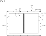
- the regulating device 10 controls the passage of the air flow F from the upstream heat exchanger 2 to the downstream heat exchanger 3 by means of rolling/unrolling blinds or curtains 11.
- the cooling module 1 may comprise a single heat exchanger, for example a cooling radiator, said regulating device 10 then being arranged upstream or downstream of said heat exchanger.
- the air flow F passing through the heat exchanger comes from the air flow F passing through the regulating device or opens onto said regulating device.
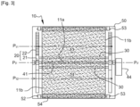
- the device 300 comprising two curtains 11 capable of moving in an opening/closing direction, between a closed position blocking the passage of the air flow and an open position allowing the air flow to pass, this regulating device comprising a transmission system 301 arranged to guide the movement of said curtains 11, as well as an actuator 40 inducing movement to the transmission system, this transmission system 301 comprising two winding shafts 302 and 303 each for winding and unwinding one of the curtains 11, this transmission system 301 further comprising at least one belt 305 operable in movement and arranged to rotate at least one of the winding shafts both in the direction of winding the curtain and in the direction of unwinding the curtain 11.
- the actuator 40 is arranged to rotate one of the winding shafts, that 303 in the figures, selectively in a winding direction of the curtain or in a unwinding direction of the curtain 11.
- Each winding shaft 302 and 303 has a toothed pinion 310 arranged to cooperate with the belt 305 which is toothed so that the movement of the winding shaft 303, a movement caused by the actuator 40, is transmitted to the other winding shaft 302.
- the regulating device 300 comprises two belts 305 each at one end of the two winding shafts 302 and 303 so that each belt 305 is associated with two toothed pinions 310 of the two winding shafts, these two belts 305 being arranged to be in synchronized movement relative to each other.
- the device 300 comprises a drive member 320 secured to a free edge 321 of the curtain 11 and arranged to move at the same time as the two belts 305 to accompany the curtain 11 during its rolling up or unrolling so as to keep the curtain 11 flat.
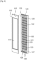
- Each drive member 320 comprises two fixing elements 322 arranged to be fixed to the two belts 305 so that the drive member 320 is secured to the two belts 305.
- Each fastener 322 is clamped onto the associated belt 305, precisely clamped onto a strip 324 forming the belt.
- the fastening element 322 associated with one of the curtains is fixed on a first strand 328 of the belt between the two winding shafts 302 and 303 and the other fastening element associated with the other of the curtains is fixed on a second strand 329 of the belt which is opposite the first strand so that the two fastening elements 322 can be moved in opposite directions, either away from each other or towards each other.
- Each drive member 320 comprises a rod 331 with at each end of the rod 331 one of the fixing elements 322, and the rod 331 being placed along a free edge 321 of the associated curtain 11. In particular when the two curtains 11 are in the closed position, the two rods 331 come to bear against each other.
- the fixing elements 322 are in particular fixed on the belt without the possibility of relative movement with respect to this belt.
- the 322 fixing elements are made of plastic.
- this curtain 11 is driven both by the winding shaft and by the drive member, at both ends.
- the simultaneous action at both ends of the curtain makes it possible to keep this curtain taut as desired, thus avoiding gathers or folds and possible jamming of the curtain.
- the invention thus makes it possible to advantageously dispense with a return spring which could be bulky and have to consume part of the torque developed by the actuator.
- the invention also makes it possible to uniformly transmit the torque of the actuator to the two winding shafts of the two curtains 11.
- the direction for winding the curtain 11 around the winding shaft is the same on both shafts. This is enabled by the fact that the curtains wind in opposite directions on the two shafts.
- the belts 305 allow the rotation of one of the winding shafts simultaneously with the translational movement of the drive member 322 of the curtain via the fixing elements.
- the shaft 303 cooperates with the actuator 40 via a cooperation tab 340. 1
Landscapes
- Engineering & Computer Science (AREA)
- Chemical & Material Sciences (AREA)
- Combustion & Propulsion (AREA)
- Transportation (AREA)
- Mechanical Engineering (AREA)
- Curtains And Furnishings For Windows Or Doors (AREA)
- Cooling, Air Intake And Gas Exhaust, And Fuel Tank Arrangements In Propulsion Units (AREA)
- Air-Conditioning For Vehicles (AREA)
Claims (9)
- Vorrichtung (300) zur Regelung eines Luftstroms (F), der dazu bestimmt ist, durch einen Wärmetauscher hindurch zu zirkulieren, für ein Kraftfahrzeug, wobei die Vorrichtung zwei Rollos (11) aufweist, die geeignet sind, sich entlang einer Öffnungs-/Schließrichtung (Z), zwischen einer geschlossenen Stellung (PF), die den Durchgang des Luftstroms (F) verschließt, und einer geöffneten Stellung (PO), die den Luftstrom (F) durchlässt, zu verlagern, wobei diese Vorrichtung zur Regelung ein Antriebssystem (301), das dazu eingerichtet ist, die Bewegung der Rollos zu führen, sowie einen Aktor (40), der eine Bewegung des Antriebssystems bewirkt, umfasst, wobei dieses Antriebssystem zwei Wickelwellen umfasst, jede zum Aufwickeln und zum Abwickeln eines der Rollos, wobei dieses Antriebssystem ferner mindestens einen Riemen (305) umfasst, der in Bewegung versetzbar ist und dazu eingerichtet ist, mindestens eine der Wickelwellen (302; 303) sowohl in die Richtung eines Aufwickelns des Rollos als auch in die Richtung eines Abwickelns des Rollos drehen zu lassen, dadurch gekennzeichnet, dass jede Wickelwelle ein Zahnrad (310) umfasst, das dazu eingerichtet ist, mit dem Riemen zusammenzuwirken, der formgezahnt ist, so dass die Bewegung der einen der Wickelwellen, insbesondere eine von dem Aktor ausgelöste Bewegung, auf die andere Wickelwelle übertragen wird.
- Vorrichtung nach dem vorhergehenden Anspruch, wobei der Aktor (40) dazu eingerichtet ist, die eine der Wickelwellen (303) selektiv in eine Aufwickelrichtung des Rollos oder in eine Abwickelrichtung des Rollos drehen zu lassen.
- Vorrichtung nach einem der vorhergehenden Ansprüche, wobei die Vorrichtung zur Regelung zwei Riemen (305) umfasst, jeden an einem der Enden der beiden Wickelwellen (302; 303), so dass jeder Riemen zwei Zahnrädern der beiden Wickelwellen zugeordnet ist, wobei diese beiden Riemen dazu eingerichtet sind, zueinander synchronisiert in Bewegung zu sein.
- Vorrichtung nach einem der vorhergehenden Ansprüche, wobei die Vorrichtung mindestens ein Mitnahmeorgan (320) umfasst, das mit einem freien Rand des Rollos fest verbunden ist und dazu eingerichtet ist, sich gleichzeitig mit dem Riemen zu verlagern, um das Rollo bei seinem Aufwickeln oder seinem Abwickeln zu begleiten, so dass das Rollo flach gehalten wird.
- Vorrichtung nach dem vorhergehenden Anspruch, wobei das Mitnahmeorgan (320) Befestigungselemente (322) umfasst, die dazu eingerichtet sind, an den Riemen befestigt zu werden, so dass das Mitnahmeorgan mit den beiden Riemen fest verbunden ist.
- Vorrichtung nach dem vorhergehenden Anspruch, wobei das Befestigungselement (322) an den zugeordneten Riemen geklemmt ist, insbesondere an einen den Riemen bildenden Streifen geklemmt ist.
- Vorrichtung nach einem der vorhergehenden Ansprüche, wobei, bei jedem Riemen, das einem der Rollos zugeordnete Befestigungselement an einem ersten Trum (328) des Riemens zwischen den beiden Wickelwellen befestigt ist und das dem anderen der Rollos zugeordnete Befestigungselement an einem zweiten Trum (329) des Riemens befestigt ist, das zu dem ersten Trum entgegengesetzt ist, so dass die beiden Befestigungselemente in entgegengesetzte Richtungen verlagert werden können, entweder voneinander weg oder zueinander hin.
- Vorrichtung nach einem der drei vorhergehenden Ansprüche, wobei das Mitnahmeorgan (320) einen Stab (331) mit einem der Befestigungselemente an jedem Ende des Stabs umfasst und wobei der Stab entlang eines freien Rands (321) des zugeordneten Rollos angeordnet ist.
- Verfahren zum Öffnen oder Schließen des Rollos einer Vorrichtung nach einem der vorhergehenden Ansprüche, wobei dieses Rollo (11) sowohl von der Wickelwelle als auch von dem Mitnahmeorgan, an den beiden Enden, mitgenommen wird, insbesondere ohne Mitwirkung einer zusätzlichen Rückstellfeder.
Applications Claiming Priority (2)
| Application Number | Priority Date | Filing Date | Title |
|---|---|---|---|
| FR1908294A FR3099091B1 (fr) | 2019-07-22 | 2019-07-22 | Dispositif de régulation d’un flux d’air d’un véhicule automobile |
| PCT/FR2020/051037 WO2021014059A1 (fr) | 2019-07-22 | 2020-06-16 | Dispositif de regulation d'un flux d'air d'un vehicule automobile |
Publications (2)
| Publication Number | Publication Date |
|---|---|
| EP4003769A1 EP4003769A1 (de) | 2022-06-01 |
| EP4003769B1 true EP4003769B1 (de) | 2025-01-08 |
Family
ID=68501783
Family Applications (1)
| Application Number | Title | Priority Date | Filing Date |
|---|---|---|---|
| EP20742351.8A Active EP4003769B1 (de) | 2019-07-22 | 2020-06-16 | Vorrichtung zur regelung eines luftstroms eines kraftfahrzeuges |
Country Status (3)
| Country | Link |
|---|---|
| EP (1) | EP4003769B1 (de) |
| FR (1) | FR3099091B1 (de) |
| WO (1) | WO2021014059A1 (de) |
Families Citing this family (1)
| Publication number | Priority date | Publication date | Assignee | Title |
|---|---|---|---|---|
| CN117227857A (zh) * | 2022-06-08 | 2023-12-15 | 北京车和家汽车科技有限公司 | 进气格栅及车辆 |
Citations (1)
| Publication number | Priority date | Publication date | Assignee | Title |
|---|---|---|---|---|
| FR3079917A1 (fr) * | 2018-04-09 | 2019-10-11 | Valeo Systemes Thermiques | Dispositif de regulation d'un flux d'air circulant au sein d'un echangeur de chaleur pour vehicule automobile et module de refroidissement muni d'un tel dispositif. |
Family Cites Families (5)
| Publication number | Priority date | Publication date | Assignee | Title |
|---|---|---|---|---|
| GB119375A (en) * | 1918-01-17 | 1918-10-03 | S E Saunders Ltd | Improvements in Screens for Regulating the Admission of Air to Aircraft and other Radiators. |
| KR101527881B1 (ko) * | 2009-07-01 | 2015-06-10 | 한라비스테온공조 주식회사 | 에어 플랩 |
| DE102011009778A1 (de) * | 2011-01-29 | 2012-08-02 | Brose Fahrzeugteile Gmbh & Co. Kg, Coburg | Verschlussvorrichtung des Lufteinlasses eines KFZ-Kühlers |
| DE102014113067A1 (de) * | 2014-09-10 | 2016-03-10 | Dr. Ing. H.C. F. Porsche Aktiengesellschaft | Vorrichtung zum Regulieren von Kühlluft bei einem Kraftfahrzeug |
| FR3063338B1 (fr) * | 2017-02-28 | 2019-05-10 | Valeo Systemes Thermiques | Dispositif de regulation d'un flux d'air |
-
2019
- 2019-07-22 FR FR1908294A patent/FR3099091B1/fr active Active
-
2020
- 2020-06-16 EP EP20742351.8A patent/EP4003769B1/de active Active
- 2020-06-16 WO PCT/FR2020/051037 patent/WO2021014059A1/fr not_active Ceased
Patent Citations (1)
| Publication number | Priority date | Publication date | Assignee | Title |
|---|---|---|---|---|
| FR3079917A1 (fr) * | 2018-04-09 | 2019-10-11 | Valeo Systemes Thermiques | Dispositif de regulation d'un flux d'air circulant au sein d'un echangeur de chaleur pour vehicule automobile et module de refroidissement muni d'un tel dispositif. |
Also Published As
| Publication number | Publication date |
|---|---|
| EP4003769A1 (de) | 2022-06-01 |
| FR3099091B1 (fr) | 2021-10-08 |
| WO2021014059A1 (fr) | 2021-01-28 |
| FR3099091A1 (fr) | 2021-01-29 |
Similar Documents
| Publication | Publication Date | Title |
|---|---|---|
| EP3568311B1 (de) | Vorrichtung zur steuerung eines luftstroms | |
| EP3774430A1 (de) | Vorrichtung zur steuerung eines in einem wärmetauscher zirkulierenden luftstroms für ein kraftfahrzeug und kühlmodul mit einer solchen vorrichtung | |
| EP4003769B1 (de) | Vorrichtung zur regelung eines luftstroms eines kraftfahrzeuges | |
| FR3079916A1 (fr) | Dispositif de regulation d'un flux d'air circulant au sein d'un echangeur de chaleur pour vehicule automobile et module de refroidissement muni d'un tel dispositif. | |
| FR3099092A1 (fr) | Dispositif de régulation d’un flux d’air d’un véhicule automobile | |
| WO2021094679A1 (fr) | Dispositif de regulation d'un flux d'air d'un vehicule automobile | |
| EP4210983A1 (de) | Wärmetauschermodul und entsprechendes kraftfahrzeug | |
| FR3121078A1 (fr) | Dispositif de régulation d’un flux d’air d’un véhicule automobile | |
| FR3121077A1 (fr) | Dispositif de régulation d’un flux d’air d’un véhicule automobile | |
| EP3589512A1 (de) | Vorrichtung zur regelung einer luftströmung in einem ersten wärmetauscher für ein kraftfahrzeug | |
| FR3077623A1 (fr) | Dispositif de regulation d’un flux d’air | |
| FR3104077A1 (fr) | Dispositif de régulation d’un flux d’air d’un véhicule automobile | |
| WO2021214000A1 (fr) | Dispositif de regulation d'un flux d'air d'un vehicule automobile | |
| WO2021170926A1 (fr) | Dispositif de regulation d'un flux d'air d'un vehicule automobile | |
| FR3103519A1 (fr) | Dispositif de régulation d’un flux d’air d’un véhicule automobile | |
| FR3103518A1 (fr) | Dispositif de régulation d’un flux d’air d’un véhicule automobile | |
| WO2022152894A1 (fr) | Dispositif de regulation d'un flux d'air d'un vehicule automobile | |
| EP4116126B1 (de) | Lufteinlassverschlussvorrichtung für ein kraftfahrzeug mit automatischem rückstellsystem | |
| FR3102101A1 (fr) | Dispositif de régulation d’un flux d’air d’un véhicule automobile | |
| WO2022157087A1 (fr) | Dispositif de régulation d'un flux d'air d'un véhicule automobile | |
| WO2021176155A1 (fr) | Dispositif de regulation d'un flux d'air d'un vehicule automobile | |
| FR3151897A1 (fr) | Dispositif d’obturation d’un flux d’air pour un véhicule automobile | |
| EP4139150A1 (de) | Luftstromregelvorrichtung für ein kraftfahrzeug | |
| FR3119116A1 (fr) | Dispositif de régulation d’un flux d’air d’un véhicule automobile | |
| WO2022233809A1 (fr) | Module de regulation thermique pour vehicule automobile |
Legal Events
| Date | Code | Title | Description |
|---|---|---|---|
| STAA | Information on the status of an ep patent application or granted ep patent |
Free format text: STATUS: UNKNOWN |
|
| STAA | Information on the status of an ep patent application or granted ep patent |
Free format text: STATUS: THE INTERNATIONAL PUBLICATION HAS BEEN MADE |
|
| PUAI | Public reference made under article 153(3) epc to a published international application that has entered the european phase |
Free format text: ORIGINAL CODE: 0009012 |
|
| STAA | Information on the status of an ep patent application or granted ep patent |
Free format text: STATUS: REQUEST FOR EXAMINATION WAS MADE |
|
| 17P | Request for examination filed |
Effective date: 20220111 |
|
| AK | Designated contracting states |
Kind code of ref document: A1 Designated state(s): AL AT BE BG CH CY CZ DE DK EE ES FI FR GB GR HR HU IE IS IT LI LT LU LV MC MK MT NL NO PL PT RO RS SE SI SK SM TR |
|
| DAV | Request for validation of the european patent (deleted) | ||
| DAX | Request for extension of the european patent (deleted) | ||
| P01 | Opt-out of the competence of the unified patent court (upc) registered |
Effective date: 20230528 |
|
| GRAP | Despatch of communication of intention to grant a patent |
Free format text: ORIGINAL CODE: EPIDOSNIGR1 |
|
| STAA | Information on the status of an ep patent application or granted ep patent |
Free format text: STATUS: GRANT OF PATENT IS INTENDED |
|
| INTG | Intention to grant announced |
Effective date: 20240730 |
|
| GRAS | Grant fee paid |
Free format text: ORIGINAL CODE: EPIDOSNIGR3 |
|
| GRAA | (expected) grant |
Free format text: ORIGINAL CODE: 0009210 |
|
| STAA | Information on the status of an ep patent application or granted ep patent |
Free format text: STATUS: THE PATENT HAS BEEN GRANTED |
|
| AK | Designated contracting states |
Kind code of ref document: B1 Designated state(s): AL AT BE BG CH CY CZ DE DK EE ES FI FR GB GR HR HU IE IS IT LI LT LU LV MC MK MT NL NO PL PT RO RS SE SI SK SM TR |
|
| REG | Reference to a national code |
Ref country code: GB Ref legal event code: FG4D Free format text: NOT ENGLISH |
|
| REG | Reference to a national code |
Ref country code: CH Ref legal event code: EP |
|
| REG | Reference to a national code |
Ref country code: DE Ref legal event code: R096 Ref document number: 602020044506 Country of ref document: DE |
|
| REG | Reference to a national code |
Ref country code: IE Ref legal event code: FG4D Free format text: LANGUAGE OF EP DOCUMENT: FRENCH |
|
| REG | Reference to a national code |
Ref country code: LT Ref legal event code: MG9D |
|
| REG | Reference to a national code |
Ref country code: NL Ref legal event code: MP Effective date: 20250108 |
|
| REG | Reference to a national code |
Ref country code: AT Ref legal event code: MK05 Ref document number: 1758117 Country of ref document: AT Kind code of ref document: T Effective date: 20250108 |
|
| PG25 | Lapsed in a contracting state [announced via postgrant information from national office to epo] |
Ref country code: NL Free format text: LAPSE BECAUSE OF FAILURE TO SUBMIT A TRANSLATION OF THE DESCRIPTION OR TO PAY THE FEE WITHIN THE PRESCRIBED TIME-LIMIT Effective date: 20250108 |
|
| PG25 | Lapsed in a contracting state [announced via postgrant information from national office to epo] |
Ref country code: RS Free format text: LAPSE BECAUSE OF FAILURE TO SUBMIT A TRANSLATION OF THE DESCRIPTION OR TO PAY THE FEE WITHIN THE PRESCRIBED TIME-LIMIT Effective date: 20250408 |
|
| PG25 | Lapsed in a contracting state [announced via postgrant information from national office to epo] |
Ref country code: FI Free format text: LAPSE BECAUSE OF FAILURE TO SUBMIT A TRANSLATION OF THE DESCRIPTION OR TO PAY THE FEE WITHIN THE PRESCRIBED TIME-LIMIT Effective date: 20250108 |
|
| PG25 | Lapsed in a contracting state [announced via postgrant information from national office to epo] |
Ref country code: PL Free format text: LAPSE BECAUSE OF FAILURE TO SUBMIT A TRANSLATION OF THE DESCRIPTION OR TO PAY THE FEE WITHIN THE PRESCRIBED TIME-LIMIT Effective date: 20250108 |
|
| PGFP | Annual fee paid to national office [announced via postgrant information from national office to epo] |
Ref country code: DE Payment date: 20250617 Year of fee payment: 6 |
|
| PG25 | Lapsed in a contracting state [announced via postgrant information from national office to epo] |
Ref country code: ES Free format text: LAPSE BECAUSE OF FAILURE TO SUBMIT A TRANSLATION OF THE DESCRIPTION OR TO PAY THE FEE WITHIN THE PRESCRIBED TIME-LIMIT Effective date: 20250108 |
|
| PG25 | Lapsed in a contracting state [announced via postgrant information from national office to epo] |
Ref country code: NO Free format text: LAPSE BECAUSE OF FAILURE TO SUBMIT A TRANSLATION OF THE DESCRIPTION OR TO PAY THE FEE WITHIN THE PRESCRIBED TIME-LIMIT Effective date: 20250408 Ref country code: IS Free format text: LAPSE BECAUSE OF FAILURE TO SUBMIT A TRANSLATION OF THE DESCRIPTION OR TO PAY THE FEE WITHIN THE PRESCRIBED TIME-LIMIT Effective date: 20250508 |
|
| PG25 | Lapsed in a contracting state [announced via postgrant information from national office to epo] |
Ref country code: HR Free format text: LAPSE BECAUSE OF FAILURE TO SUBMIT A TRANSLATION OF THE DESCRIPTION OR TO PAY THE FEE WITHIN THE PRESCRIBED TIME-LIMIT Effective date: 20250108 |
|
| PG25 | Lapsed in a contracting state [announced via postgrant information from national office to epo] |
Ref country code: LV Free format text: LAPSE BECAUSE OF FAILURE TO SUBMIT A TRANSLATION OF THE DESCRIPTION OR TO PAY THE FEE WITHIN THE PRESCRIBED TIME-LIMIT Effective date: 20250108 Ref country code: PT Free format text: LAPSE BECAUSE OF FAILURE TO SUBMIT A TRANSLATION OF THE DESCRIPTION OR TO PAY THE FEE WITHIN THE PRESCRIBED TIME-LIMIT Effective date: 20250508 |
|
| PGFP | Annual fee paid to national office [announced via postgrant information from national office to epo] |
Ref country code: FR Payment date: 20250630 Year of fee payment: 6 |
|
| PG25 | Lapsed in a contracting state [announced via postgrant information from national office to epo] |
Ref country code: GR Free format text: LAPSE BECAUSE OF FAILURE TO SUBMIT A TRANSLATION OF THE DESCRIPTION OR TO PAY THE FEE WITHIN THE PRESCRIBED TIME-LIMIT Effective date: 20250409 Ref country code: BG Free format text: LAPSE BECAUSE OF FAILURE TO SUBMIT A TRANSLATION OF THE DESCRIPTION OR TO PAY THE FEE WITHIN THE PRESCRIBED TIME-LIMIT Effective date: 20250108 |
|
| PG25 | Lapsed in a contracting state [announced via postgrant information from national office to epo] |
Ref country code: AT Free format text: LAPSE BECAUSE OF FAILURE TO SUBMIT A TRANSLATION OF THE DESCRIPTION OR TO PAY THE FEE WITHIN THE PRESCRIBED TIME-LIMIT Effective date: 20250108 |
|
| PG25 | Lapsed in a contracting state [announced via postgrant information from national office to epo] |
Ref country code: SE Free format text: LAPSE BECAUSE OF FAILURE TO SUBMIT A TRANSLATION OF THE DESCRIPTION OR TO PAY THE FEE WITHIN THE PRESCRIBED TIME-LIMIT Effective date: 20250108 |
|
| PG25 | Lapsed in a contracting state [announced via postgrant information from national office to epo] |
Ref country code: SM Free format text: LAPSE BECAUSE OF FAILURE TO SUBMIT A TRANSLATION OF THE DESCRIPTION OR TO PAY THE FEE WITHIN THE PRESCRIBED TIME-LIMIT Effective date: 20250108 |
|
| REG | Reference to a national code |
Ref country code: DE Ref legal event code: R097 Ref document number: 602020044506 Country of ref document: DE |
|
| PG25 | Lapsed in a contracting state [announced via postgrant information from national office to epo] |
Ref country code: DK Free format text: LAPSE BECAUSE OF FAILURE TO SUBMIT A TRANSLATION OF THE DESCRIPTION OR TO PAY THE FEE WITHIN THE PRESCRIBED TIME-LIMIT Effective date: 20250108 |
|
| PG25 | Lapsed in a contracting state [announced via postgrant information from national office to epo] |
Ref country code: CZ Free format text: LAPSE BECAUSE OF FAILURE TO SUBMIT A TRANSLATION OF THE DESCRIPTION OR TO PAY THE FEE WITHIN THE PRESCRIBED TIME-LIMIT Effective date: 20250108 Ref country code: EE Free format text: LAPSE BECAUSE OF FAILURE TO SUBMIT A TRANSLATION OF THE DESCRIPTION OR TO PAY THE FEE WITHIN THE PRESCRIBED TIME-LIMIT Effective date: 20250108 |
|
| PG25 | Lapsed in a contracting state [announced via postgrant information from national office to epo] |
Ref country code: RO Free format text: LAPSE BECAUSE OF FAILURE TO SUBMIT A TRANSLATION OF THE DESCRIPTION OR TO PAY THE FEE WITHIN THE PRESCRIBED TIME-LIMIT Effective date: 20250108 |
|
| PG25 | Lapsed in a contracting state [announced via postgrant information from national office to epo] |
Ref country code: SK Free format text: LAPSE BECAUSE OF FAILURE TO SUBMIT A TRANSLATION OF THE DESCRIPTION OR TO PAY THE FEE WITHIN THE PRESCRIBED TIME-LIMIT Effective date: 20250108 |
|
| PLBE | No opposition filed within time limit |
Free format text: ORIGINAL CODE: 0009261 |
|
| STAA | Information on the status of an ep patent application or granted ep patent |
Free format text: STATUS: NO OPPOSITION FILED WITHIN TIME LIMIT |
|
| REG | Reference to a national code |
Ref country code: CH Ref legal event code: L10 Free format text: ST27 STATUS EVENT CODE: U-0-0-L10-L00 (AS PROVIDED BY THE NATIONAL OFFICE) Effective date: 20251119 |
|
| 26N | No opposition filed |
Effective date: 20251009 |
|
| REG | Reference to a national code |
Ref country code: CH Ref legal event code: H13 Free format text: ST27 STATUS EVENT CODE: U-0-0-H10-H13 (AS PROVIDED BY THE NATIONAL OFFICE) Effective date: 20260127 |
|
| PG25 | Lapsed in a contracting state [announced via postgrant information from national office to epo] |
Ref country code: IT Free format text: LAPSE BECAUSE OF FAILURE TO SUBMIT A TRANSLATION OF THE DESCRIPTION OR TO PAY THE FEE WITHIN THE PRESCRIBED TIME-LIMIT Effective date: 20250108 |
|
| PG25 | Lapsed in a contracting state [announced via postgrant information from national office to epo] |
Ref country code: MC Free format text: LAPSE BECAUSE OF FAILURE TO SUBMIT A TRANSLATION OF THE DESCRIPTION OR TO PAY THE FEE WITHIN THE PRESCRIBED TIME-LIMIT Effective date: 20250108 |
|
| PG25 | Lapsed in a contracting state [announced via postgrant information from national office to epo] |
Ref country code: LU Free format text: LAPSE BECAUSE OF NON-PAYMENT OF DUE FEES Effective date: 20250616 |
|
| GBPC | Gb: european patent ceased through non-payment of renewal fee |
Effective date: 20250616 |
|
| REG | Reference to a national code |
Ref country code: BE Ref legal event code: MM Effective date: 20250630 |
|
| PG25 | Lapsed in a contracting state [announced via postgrant information from national office to epo] |
Ref country code: GB Free format text: LAPSE BECAUSE OF NON-PAYMENT OF DUE FEES Effective date: 20250616 |
|
| PG25 | Lapsed in a contracting state [announced via postgrant information from national office to epo] |
Ref country code: IE Free format text: LAPSE BECAUSE OF NON-PAYMENT OF DUE FEES Effective date: 20250616 |
|
| PG25 | Lapsed in a contracting state [announced via postgrant information from national office to epo] |
Ref country code: BE Free format text: LAPSE BECAUSE OF NON-PAYMENT OF DUE FEES Effective date: 20250630 |
|
| PG25 | Lapsed in a contracting state [announced via postgrant information from national office to epo] |
Ref country code: CH Free format text: LAPSE BECAUSE OF NON-PAYMENT OF DUE FEES Effective date: 20250630 |