EP4003769B1 - Dispositif de regulation d'un flux d'air d'un vehicule automobile - Google Patents
Dispositif de regulation d'un flux d'air d'un vehicule automobile Download PDFInfo
- Publication number
- EP4003769B1 EP4003769B1 EP20742351.8A EP20742351A EP4003769B1 EP 4003769 B1 EP4003769 B1 EP 4003769B1 EP 20742351 A EP20742351 A EP 20742351A EP 4003769 B1 EP4003769 B1 EP 4003769B1
- Authority
- EP
- European Patent Office
- Prior art keywords
- curtain
- belt
- winding
- curtains
- air flow
- Prior art date
- Legal status (The legal status is an assumption and is not a legal conclusion. Google has not performed a legal analysis and makes no representation as to the accuracy of the status listed.)
- Active
Links
Images




Classifications
-
- B—PERFORMING OPERATIONS; TRANSPORTING
- B60—VEHICLES IN GENERAL
- B60K—ARRANGEMENT OR MOUNTING OF PROPULSION UNITS OR OF TRANSMISSIONS IN VEHICLES; ARRANGEMENT OR MOUNTING OF PLURAL DIVERSE PRIME-MOVERS IN VEHICLES; AUXILIARY DRIVES FOR VEHICLES; INSTRUMENTATION OR DASHBOARDS FOR VEHICLES; ARRANGEMENTS IN CONNECTION WITH COOLING, AIR INTAKE, GAS EXHAUST OR FUEL SUPPLY OF PROPULSION UNITS IN VEHICLES
- B60K11/00—Arrangement in connection with cooling of propulsion units
- B60K11/08—Air inlets for cooling; Shutters or blinds therefor
- B60K11/085—Air inlets for cooling; Shutters or blinds therefor with adjustable shutters or blinds
-
- F—MECHANICAL ENGINEERING; LIGHTING; HEATING; WEAPONS; BLASTING
- F01—MACHINES OR ENGINES IN GENERAL; ENGINE PLANTS IN GENERAL; STEAM ENGINES
- F01P—COOLING OF MACHINES OR ENGINES IN GENERAL; COOLING OF INTERNAL-COMBUSTION ENGINES
- F01P7/00—Controlling of coolant flow
- F01P7/02—Controlling of coolant flow the coolant being cooling-air
- F01P7/10—Controlling of coolant flow the coolant being cooling-air by throttling amount of air flowing through liquid-to-air heat exchangers
-
- Y—GENERAL TAGGING OF NEW TECHNOLOGICAL DEVELOPMENTS; GENERAL TAGGING OF CROSS-SECTIONAL TECHNOLOGIES SPANNING OVER SEVERAL SECTIONS OF THE IPC; TECHNICAL SUBJECTS COVERED BY FORMER USPC CROSS-REFERENCE ART COLLECTIONS [XRACs] AND DIGESTS
- Y02—TECHNOLOGIES OR APPLICATIONS FOR MITIGATION OR ADAPTATION AGAINST CLIMATE CHANGE
- Y02T—CLIMATE CHANGE MITIGATION TECHNOLOGIES RELATED TO TRANSPORTATION
- Y02T10/00—Road transport of goods or passengers
- Y02T10/80—Technologies aiming to reduce greenhouse gasses emissions common to all road transportation technologies
- Y02T10/88—Optimized components or subsystems, e.g. lighting, actively controlled glasses
Definitions
- the invention relates to a device for regulating an air flow circulating within a heat exchanger for a motor vehicle and a cooling module provided with such a device. It is in particular intended for equipping a front face of a motor vehicle.
- AGS Active Grille Shutter
- the AGS is preferably installed at the level of a grille of the motor vehicle. In the open position of the air intake, the air can circulate through the grille and participate in particular in cooling the engine of the motor vehicle. In the closed position of the air intake, the air does not enter via the grille, which reduces drag and thus reduces fuel consumption and carbon dioxide emissions. The AGS therefore reduces energy consumption and pollution when the engine does not need to be cooled by outside air.
- Cooling modules for motor vehicles comprising two heat exchangers are known.
- a first heat exchanger has the function of cooling an auxiliary circuit of the vehicle, such as an air conditioning system or a charge air cooling system.
- a second heat exchanger is necessary for cooling the engine of the vehicle.
- the heat exchangers are arranged on the front of the vehicle, assembled and aligned in series to be successively crossed by the flow of air entering through the grille of the vehicle. They typically comprise a heat exchange bundle, comprising tubes in which the fluid to be cooled circulates and through which air from the radiator grille passes.
- the regulating device comprises two curtains mounted in a frame and movable alternately in translation between two open and closed positions. By moving between these two positions, the curtains allow the regulating device to alternately allow or block the air flow passing through the grille of the motor vehicle.
- the movement of the curtains is carried out by means of a transmission system which guides the movement of said curtains in translation, as well as an actuator inducing movement to the transmission system.
- Such a regulating device is known from FR3063338A1 .
- the invention thus relates to a device for regulating an air flow intended to circulate through a heat exchanger for a motor vehicle, the device comprising two curtains capable of moving in an opening/closing direction, between a closed position blocking the passage of the air flow and an open position allowing the air flow to pass, this regulation device comprising a transmission system arranged to guide the movement of said curtains, as well as an actuator inducing movement to the transmission system, this transmission system comprising two winding shafts each for winding and unwinding one of the curtains, this transmission system further comprising at least one belt that can be actuated in movement and arranged to rotate at least one of the winding shafts both in the direction of winding the curtain and in the direction of unwinding the curtain, characterized in that each winding shaft comprises a toothed pinion arranged to cooperate with the belt which is notched so that the movement of one winding shafts, including a movement caused by the actuator, is transmitted to the other winding shaft,
- the actuator is arranged to rotate one of the winding shafts selectively in a winding direction of the curtain or in a unwinding direction of the curtain.
- the regulating device comprises two belts each at one end of the two winding shafts so that each belt is associated with two toothed pinions of the two winding shafts, these two belts being arranged to be in synchronized movement relative to each other.
- the device comprises at least one drive member secured to a free edge of the curtain and arranged to move at the same time as the belt to accompany the curtain when it is rolled up or unrolled so as to keep the curtain flat.
- the drive member comprises fixing elements arranged to be fixed to the belts so that the drive member is secured to the two belts.
- each fastening element is clamped on the associated belt, in particular clamped on a strip forming the belt.
- the fastening element associated with one of the curtains is fixed on a first strand of the belt between the two winding shafts and the other fastening element associated with the other of the curtains is fixed on a second strand of the belt which is opposite the first strand so that the two fastening elements can be moved in opposite directions, either away from each other or towards each other.
- the drive member comprises a rod with at each end of the rod one of the fixing elements, and the rod being placed along a free edge of the associated curtain.
- the two rods come to bear against each other.
- the fixing elements are in particular fixed on the belt without the possibility of relative movement in relation to this belt.
- each fixing element is made of plastic.
- this curtain is driven both by the winding shaft and by the drive member, at both ends.
- the simultaneous action at both ends of the curtain makes it possible to keep this curtain taut as desired, thus avoiding gathers or folds and possible jamming of the curtain.
- the invention thus makes it possible to advantageously do away with a return spring which could be bulky and have to consume part of the torque developed by the actuator.
- the invention also makes it possible to uniformly transmit the torque of the actuator to the two winding shafts of the two curtains.
- the direction for winding the curtain around the winding shaft is the same on both shafts. This is enabled by the fact that the curtains wind in opposite directions on the two shafts.
- the belt thus allows the rotation of one of the winding shafts simultaneously with the translational movement of the curtain drive member via the fixing elements.
- the invention also relates to a method for opening or closing the curtain of a device according to one of the preceding claims, this curtain is driven both by the winding shaft and by the drive member, respectively at the two ends, in particular without the intervention of an additional return spring.
- FIG. 1 illustrates a device 10 for regulating an air flow F and a cooling module 1, according to a side view.
- the cooling module 1 extends in depth in a direction X intended to correspond to the longitudinal axis of the equipped vehicle.
- the air flow F flows substantially parallel to the direction X.
- the module is configured to be fixed to a support, such as a chassis of the vehicle.
- Cooling module 1 includes an upstream heat exchanger 2 (located on the left on the fig. 1 ) and a downstream heat exchanger 3 (located on the right on the fig. 1 ) arranged in series according to the direction of flow of the air flow F passing through them.
- the cooling module 1 is configured to be arranged on its support, so that the upstream heat exchanger 2 is crossed by the air flow F first and the downstream heat exchanger 3 second.
- the upstream heat exchanger 2 is a cooling radiator, called low temperature, used to cool a coolant of a heat exchange loop, called low temperature, comprising, in particular, an air conditioning condenser and/or a charge air cooler.
- the downstream heat exchanger 3 is, for example, a high temperature cooling radiator intended to cool a coolant of a heat exchange loop comprising an engine of the vehicle. The air which passes through this downstream exchanger 3 cools the coolant of the engine.
- Each exchanger 2, 3 comprises, for example, a heat exchange bundle and collection chambers arranged laterally on either side of the bundle (not shown).
- the bundle is crossed by the air flow F. It comprises a set of tubes parallel to each other, opening into the collection chambers, for the circulation of the coolant (not shown).
- the cooling module 1 is advantageously configured to allow a flow of air in a substantially sealed manner between said heat exchangers 2, 3, that is to say that the upstream heat exchanger 2 and the downstream heat exchanger 3 are assembled together so that the downstream heat exchanger 3 is not directly crossed by air coming from outside the module.
- the air flow F passing through the downstream heat exchanger 3 comes from the air flow passing through the upstream heat exchanger 2.
- the cooling module 1 may, for example, comprise sealing means making it possible to guide the entire air flow having passed through the upstream heat exchanger 2 towards the downstream heat exchanger 3 without loss of air flow.
- These sealing means may for example comprise a sheath arranged between the two heat exchangers 2, 3.
- the module advantageously comprises a motor-fan unit 10 capable of circulating the air in the cooling module 1.
- the motor-fan group 4 is here arranged downstream of the downstream heat exchanger 3, the group motor fan 4 being configured to draw air from an air inlet of the vehicle, which is preferably defined by its grille.
- the cooling module 1 further comprises an air flow regulating device 10 preferably arranged between the upstream heat exchanger 2 and the downstream heat exchanger 3.
- the regulating device 10 has a small thickness in the depth of the cooling module.
- the regulating device 10 controls the passage of the air flow F from the upstream heat exchanger 2 to the downstream heat exchanger 3 by means of rolling/unrolling blinds or curtains 11.
- the cooling module 1 may comprise a single heat exchanger, for example a cooling radiator, said regulating device 10 then being arranged upstream or downstream of said heat exchanger.
- the air flow F passing through the heat exchanger comes from the air flow F passing through the regulating device or opens onto said regulating device.
- the device 300 comprising two curtains 11 capable of moving in an opening/closing direction, between a closed position blocking the passage of the air flow and an open position allowing the air flow to pass, this regulating device comprising a transmission system 301 arranged to guide the movement of said curtains 11, as well as an actuator 40 inducing movement to the transmission system, this transmission system 301 comprising two winding shafts 302 and 303 each for winding and unwinding one of the curtains 11, this transmission system 301 further comprising at least one belt 305 operable in movement and arranged to rotate at least one of the winding shafts both in the direction of winding the curtain and in the direction of unwinding the curtain 11.
- the actuator 40 is arranged to rotate one of the winding shafts, that 303 in the figures, selectively in a winding direction of the curtain or in a unwinding direction of the curtain 11.
- Each winding shaft 302 and 303 has a toothed pinion 310 arranged to cooperate with the belt 305 which is toothed so that the movement of the winding shaft 303, a movement caused by the actuator 40, is transmitted to the other winding shaft 302.
- the regulating device 300 comprises two belts 305 each at one end of the two winding shafts 302 and 303 so that each belt 305 is associated with two toothed pinions 310 of the two winding shafts, these two belts 305 being arranged to be in synchronized movement relative to each other.
- the device 300 comprises a drive member 320 secured to a free edge 321 of the curtain 11 and arranged to move at the same time as the two belts 305 to accompany the curtain 11 during its rolling up or unrolling so as to keep the curtain 11 flat.
- Each drive member 320 comprises two fixing elements 322 arranged to be fixed to the two belts 305 so that the drive member 320 is secured to the two belts 305.
- Each fastener 322 is clamped onto the associated belt 305, precisely clamped onto a strip 324 forming the belt.
- the fastening element 322 associated with one of the curtains is fixed on a first strand 328 of the belt between the two winding shafts 302 and 303 and the other fastening element associated with the other of the curtains is fixed on a second strand 329 of the belt which is opposite the first strand so that the two fastening elements 322 can be moved in opposite directions, either away from each other or towards each other.
- Each drive member 320 comprises a rod 331 with at each end of the rod 331 one of the fixing elements 322, and the rod 331 being placed along a free edge 321 of the associated curtain 11. In particular when the two curtains 11 are in the closed position, the two rods 331 come to bear against each other.
- the fixing elements 322 are in particular fixed on the belt without the possibility of relative movement with respect to this belt.
- the 322 fixing elements are made of plastic.
- this curtain 11 is driven both by the winding shaft and by the drive member, at both ends.
- the simultaneous action at both ends of the curtain makes it possible to keep this curtain taut as desired, thus avoiding gathers or folds and possible jamming of the curtain.
- the invention thus makes it possible to advantageously dispense with a return spring which could be bulky and have to consume part of the torque developed by the actuator.
- the invention also makes it possible to uniformly transmit the torque of the actuator to the two winding shafts of the two curtains 11.
- the direction for winding the curtain 11 around the winding shaft is the same on both shafts. This is enabled by the fact that the curtains wind in opposite directions on the two shafts.
- the belts 305 allow the rotation of one of the winding shafts simultaneously with the translational movement of the drive member 322 of the curtain via the fixing elements.
- the shaft 303 cooperates with the actuator 40 via a cooperation tab 340. 1
Landscapes
- Engineering & Computer Science (AREA)
- Chemical & Material Sciences (AREA)
- Combustion & Propulsion (AREA)
- Transportation (AREA)
- Mechanical Engineering (AREA)
- Curtains And Furnishings For Windows Or Doors (AREA)
- Air-Conditioning For Vehicles (AREA)
- Cooling, Air Intake And Gas Exhaust, And Fuel Tank Arrangements In Propulsion Units (AREA)
Description
- L'invention concerne un dispositif de régulation d'un flux d'air circulant au sein d'un échangeur de chaleur pour véhicule automobile et un module de refroidissement muni d'un tel dispositif. Elle est en particulier destinée à l'équipement d'une face avant de véhicule automobile.
- Il est connu d'utiliser des volets pilotés par un actionneur en face avant de véhicule afin de réduire le coefficient de traînée et aussi d'améliorer les performances de refroidissement et de climatisation. Un tel système est le plus souvent désigné par l'acronyme AGS provenant de l'expression de langue anglaise « Active Grille Shutter ». L'AGS est de préférence installé au niveau d'une calandre du véhicule automobile. En position d'ouverture de l'entrée d'air, l'air peut circuler à travers la calandre et participer notamment au refroidissement du moteur du véhicule automobile. En position d'obturation de l'entrée d'air, l'air ne pénètre pas via la calandre ce qui réduit la traînée et permet ainsi de réduire la consommation de carburant et l'émission de dioxyde de carbone. L'AGS permet donc de réduire la consommation d'énergie et la pollution lorsque le moteur n'a pas besoin d'être refroidi par l'air extérieur.
- Dans certains cas, il n'est pas possible de positionner un AGS au niveau de la calandre, devant les échangeurs, à cause d'un environnement inadapté, d'un souhait de client ou autre.
- Il est connu des modules de refroidissement pour véhicule automobile comprenant deux échangeurs de chaleur. Un premier échangeur de chaleur a pour fonction de refroidir un circuit annexe du véhicule, tel qu'un dispositif de climatisation ou un dispositif de refroidissement d'air de suralimentation. Un deuxième échangeur de chaleur est nécessaire au refroidissement du moteur du véhicule. Les échangeurs de chaleur sont disposés en face avant du véhicule, assemblés et alignés en série pour être successivement traversés par le flux d'air entrant à travers la calandre du véhicule. Ils comprennent typiquement un faisceau d'échange de chaleur, comprenant des tubes dans lesquels circule le fluide à refroidir et traversé par l'air provenant de la calandre.
- Afin de dissocier le refroidissement des deux échangeurs de chaleur et optimiser le gain aérodynamique de chaque échangeur de chaleur, le déposant a récemment proposé un dispositif de régulation du flux d'air destiné à circuler dans les échangeurs de chaleur dans une demande de brevet non publiée du déposant. Le dispositif de régulation comprend deux rideaux montés dans un cadre et déplaçables alternativement en translation entre deux positions ouverte et fermée. En se déplaçant entre ces deux positions, les rideaux permettent au dispositif de régulation de laisser passer ou obturer alternativement le flux d'air traversant la calandre du véhicule automobile. Le déplacement des rideaux s'effectue au moyen d'un système de transmission qui guide le mouvement desdits rideaux en translation, ainsi qu'un actionneur induisant un mouvement au système de transmission.
- Un tel dispositif de régulation est connu de
FR3063338A1 - L'invention a ainsi pour objet, un dispositif de régulation d'un flux d'air destiné à circuler à travers un échangeur de chaleur pour véhicule automobile, le dispositif comprenant deux rideaux aptes à se déplacer selon une direction d'ouverture/fermeture, entre une position fermée obturant le passage du flux d'air et une position ouverte laissant passer le flux d'air, ce dispositif de régulation comportant un système de transmission agencé pour guider le mouvement desdits rideaux, ainsi qu'un actionneur induisant un mouvement au système de transmission, ce système de transmission comportant deux arbres d'enroulement chacun pour l'enroulement et le déroulement de l'un des rideaux, ce système de transmission comportant en outre au moins une courroie actionnable en mouvement et agencée pour faire tourner l'un au moins des arbres d'enroulement à la fois dans le sens d'un enroulement du rideau et dans le sens d'un déroulement du rideau, caractérisé en ce que chaque arbre d'enroulement comporte un pignon denté agencé pour coopérer avec la courroie qui est crantée de sorte que le mouvement de l'un des arbres d'enroulement, notamment un mouvement provoqué par l'actionneur, soit transmis à l'autre arbre d'enroulement,
- Selon l'un des aspects de l'invention, l'actionneur est agencé pour faire tourner l'un des arbres d'enroulement sélectivement dans un sens d'enroulement du rideau ou dans un sens de déroulement du rideau.
- Selon l'un des aspects de l'invention, le dispositif de régulation comporte deux courroies chacune à l'une des extrémités des deux arbres d'enroulement de sorte que chaque courroie est associée à deux pignons dentés des deux arbres d'enroulement, ces deux courroies étant agencées pour être en mouvement synchronisé l'une par rapport à l'autre.
- Selon l'un des aspects de l'invention, le dispositif comporte au moins un organe d'entraînement solidaire d'un bord libre du rideau et agencé pour se déplacer en même temps que la courroie pour accompagner le rideau lors de son enroulement ou de son déroulement de manière à maintenir le rideau à plat.
- Selon l'un des aspects de l'invention, l'organe d'entrainement comporte des éléments de fixation agencés pour être fixés aux courroies de sorte que l'organe d'entrainement soit solidaire des deux courroies.
- Selon l'un des aspects de l'invention, chaque élément de fixation est pincé sur la courroie associée, notamment pincé sur une bande formant la courroie.
- Selon l'un des aspects de l'invention, pour chaque courroie, l'élément de fixation associé à l'un des rideaux est fixé sur un premier brin de la courroie entre les deux arbres d'enroulement et l'autre élément de fixation associé à l'autre des rideaux est fixé sur un deuxième brin de la courroie qui est opposé au premier brin de sorte que les deux éléments de fixation puissent être déplacés en directions opposées, soit en s'éloignant l'un de l'autre soit en se rapprochant l'un de l'autre.
- Selon l'un des aspects de l'invention, l'organe d'entrainement comporte une tige avec à chaque extrémité de la tige l'un des éléments de fixation, et la tige étant placée le long d'un bord libre du rideau associé. Notamment lorsque les deux rideaux sont en positon fermée, les deux tiges viennent en appui l'une contre l'autre. Les éléments de fixation sont notamment fixés sur la courroie sans possibilité de mouvement relatif par rapport à cette courroie.
- Selon l'un des aspects de l'invention, chaque élément de fixation est réalisé en matière plastique.
- Ainsi pour ouvrir ou fermer le rideau, ce rideau est entrainé à la fois par l'arbre d'enroulement et par l'organe d'entrainement, aux deux extrémités. L'action simultanée aux deux extrémités du rideau permet de maintenir ce rideau tendu comme souhaité, évitant ainsi des fronces ou plis et d'éventuels coincements du rideau. L'invention permet ainsi de s'affranchir, de manière avantageuse, d'un ressort de rappel qui pourrait être volumineux et devoir consommer une partie du couple développé par l'actionneur. L'invention permet en outre de transmettre de manière uniforme le couple de l'actionneur aux deux arbres d'enroulement des deux rideaux. Lors de l'ouverture du rideau, le rideau s'enroule autour de son arbre d'enroulement et le mouvement de la courroie ramène l'extrémité libre du rideau vers cet arbre d'enroulement via l'organe d'entrainement.
- Selon l'un des aspects de l'invention, le sens pour enrouler le rideau autour de l'arbre d'enroulement est le même sur les deux arbres. Ceci est permis par le fait que les rideaux s'enroulent de façon opposée sur les deux arbres
- Ainsi la courroie permet la rotation de l'un des arbres d'enroulement simultanément à la mise en mouvement en translation de l'organe d'entrainement du rideau via les éléments de fixation.
- L'invention a encore pour objet un procédé pour ouvrir ou fermer le rideau d'un dispositif selon l'une des revendications précédentes, ce rideau est entrainé à la fois par l'arbre d'enroulement et par l'organe d'entrainement, respectivement aux deux extrémités, notamment sans intervention d'un ressort de rappel supplémentaire
- Il est entendu que l'ensemble des caractéristiques et configurations précédemment ne sont en rien limitatives. D'autres caractéristiques, détails et avantages de l'invention ressortiront plus clairement à la lecture de la description détaillée donnée ci-après, et de plusieurs exemples de réalisation donnés à titre indicatif et non limitatif en référence aux dessins schématiques annexés, sur lesquels :
- La
figure 1 [Fig. 1 ] illustre de façon schématique, en vue de côté, la face avant d'un véhicule comprenant un module de refroidissement équipé d'un dispositif de régulation ne faisant pas partie de l'invention; - La
figure 2 [Fig. 2 ] illustre, en vue schématique de face, un dispositif de régulation ne faisant pas partie de l'invention, les rideaux sont en position ouverte, - La
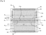
figure 3 [Fig. 3 ] illustre, en vue schématique de face, un dispositif de régulation selon l'invention, les rideaux sont en position fermée, - La
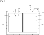
figure 4 [Fig. 4 ] est une représentation schématique d'un autre dispositif de régulation ne faisant pas partie de l'invention, - La
figure 5 [Fig. 5 ] est une représentation schématique des éléments du dispositif de lafigure 4 , - La
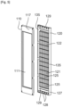
figure 6 [Fig. 6 ] est une représentation schématique d'un dispositif selon un exemple de réalisation de l'invention, en positon fermée, - La
figure 7 [Fig. 7 ] est une représentation schématique d'un dispositif selon la figure précédente, en positon ouverte, - La
figure 8 [Fig. 8 ] est une représentation schématique du dispositif selon lafigure 6 , en vue grossie, en positon fermée. - La
figure 1 illustre un dispositif de régulation 10 d'un flux d'air F ainsi qu'un module de refroidissement 1, selon une vue de côté. Le module de refroidissement 1 s'étend en profondeur selon une direction X destinée à correspondre à l'axe longitudinal du véhicule équipé. Le flux d'air F s'écoule sensiblement parallèlement à la direction X. Le module est configuré pour être fixé sur un support, tel qu'un châssis du véhicule. - Le module de refroidissement 1 comprend un échangeur de chaleur amont 2 (situé à gauche sur la
fig. 1 ) et un échangeur de chaleur aval 3 (situé à droite sur lafig. 1 ) agencés en série selon le sens d'écoulement du flux d'air F les traversant. Autrement dit, le module de refroidissement 1 est configuré pour être disposé sur son support, de sorte que l'échangeur de chaleur amont 2 soit traversé par le flux d'air F en premier et l'échangeur de chaleur aval 3 en deuxième. - L'échangeur de chaleur amont 2 est un radiateur de refroidissement, dit basse température, servant à refroidir un liquide de refroidissement d'une boucle d'échange de chaleur, dite basse température, comprenant, notamment, un condenseur de climatisation et/ou un refroidisseur d'air de suralimentation. L'échangeur de chaleur aval 3 est, par exemple, un radiateur de refroidissement haute température destiné à refroidir un liquide de refroidissement d'une boucle d'échange de chaleur comprenant un moteur du véhicule. L'air qui traverse cet échangeur aval 3 refroidit le liquide de refroidissement du moteur.
- Chaque échangeur 2, 3 comprend, par exemple, un faisceau d'échange de chaleur et des chambres de collecte disposées latéralement de part et d'autre du faisceau (non illustré). Le faisceau est traversé par le flux d'air F. Il comprend un ensemble de tubes parallèles les uns aux autres, débouchant dans les chambres de collecte, pour la circulation du liquide de refroidissement (non illustré).
- Le module de refroidissement 1 est avantageusement configuré pour autoriser un écoulement d'air de manière sensiblement étanche entre lesdits échangeurs de chaleur 2, 3, c'est-à-dire que l'échangeur de chaleur amont 2 et l'échangeur de chaleur aval 3 sont assemblés l'un à autre de sorte que l'échangeur de chaleur aval 3 ne soit pas directement traversé par de l'air venant de l'extérieur du module. Autrement dit, le flux d'air F traversant l'échangeur de chaleur aval 3 est issu du flux d'air traversant l'échangeur de chaleur amont 2. Pour cela, le module de refroidissement 1 peut, par exemple, comprendre des moyens d'étanchéité permettant de guider l'intégralité du flux d'air ayant traversé l'échangeur de chaleur amont 2 vers l'échangeur de chaleur aval 3 sans perte de débit d'air. Ces moyens d'étanchéité, non illustrés, peuvent par exemple comprendre une gaine agencée entre les deux échangeurs de chaleur 2,3.
- Pour faciliter le passage du flux d'air dans le module de refroidissement 1, notamment lorsque le véhicule est à l'arrêt, le module comprend avantageusement un groupe moto-ventilateur 10 apte à faire circuler l'air dans le module de refroidissement 1. Comme illustré sur la
figure 1 , le groupe moto-ventilateur 4 est ici disposé en aval de l'échangeur de chaleur aval 3, le groupe moto-ventilateur 4 étant configuré pour aspirer l'air depuis une entrée d'air du véhicule, qui est de préférence définie par sa calandre. - Le module de refroidissement 1 comprend, en outre, un dispositif de régulation 10 du flux d'air agencé préférentiellement entre l'échangeur de chaleur amont 2 et l'échangeur de chaleur aval 3. Le dispositif de régulation 10 présente une faible épaisseur dans la profondeur du module de refroidissement. Le dispositif de régulation 10 contrôle le passage du flux d'air F de l'échangeur de chaleur amont 2 vers l'échangeur de chaleur aval 3 par l'intermédiaire de stores ou rideaux 11 enroulables/déroulables.
- En variante, le module de refroidissement 1 peut comprendre un unique échangeur de chaleur, par exemple un radiateur de refroidissement, ledit dispositif de régulation 10 étant alors agencé en amont ou en aval dudit échangeur de chaleur. Dans une telle configuration, le flux d'air F traversant l'échangeur de chaleur est issu du flux d'air F traversant le dispositif de régulation ou débouche sur ledit dispositif de régulation.
- On a représenté sur les
figures 5 à 7 un dispositif de régulation d'un flux d'air 300 selon un exemple de réalisation de l'invention, le dispositif 300 comprenant deux rideaux 11 aptes à se déplacer selon une direction d'ouverture/fermeture, entre une position fermée obturant le passage du flux d'air et une position ouverte laissant passer le flux d'air, ce dispositif de régulation comportant un système de transmission 301 agencé pour guider le mouvement desdits rideaux 11, ainsi qu'un actionneur 40 induisant un mouvement au système de transmission, ce système de transmission 301 comportant deux arbres d'enroulement 302 et 303 chacun pour l'enroulement et le déroulement de l'un des rideaux 11, ce système de transmission 301 comportant en outre au moins une courroie 305 actionnable en mouvement et agencée pour faire tourner l'un au moins des arbres d'enroulement à la fois dans le sens d'un enroulement du rideau et dans le sens d'un déroulement du rideau 11. - L'actionneur 40 est agencé pour faire tourner l'un des arbres d'enroulement, celui 303 sur les figures, sélectivement dans un sens d'enroulement du rideau ou dans un sens de déroulement du rideau 11.
- Chaque arbre d'enroulement 302 et 303 comporte un pignon denté 310 agencé pour coopérer avec la courroie 305 qui est crantée de sorte que le mouvement de l'arbre d'enroulement 303, un mouvement provoqué par l'actionneur 40, soit transmis à l'autre arbre d'enroulement 302.
- Le dispositif de régulation 300 comporte deux courroies 305 chacune à l'une des extrémités des deux arbres d'enroulement 302 et 303 de sorte que chaque courroie 305 est associée à deux pignons dentés 310 des deux arbres d'enroulement, ces deux courroies 305 étant agencées pour être en mouvement synchronisé l'une par rapport à l'autre.
- Le dispositif 300 comporte un organe d'entraînement 320 solidaire d'un bord libre 321 du rideau 11 et agencé pour se déplacer en même temps que les deux courroies 305 pour accompagner le rideau 11 lors de son enroulement ou de son déroulement de manière à maintenir le rideau 11 à plat.
- Chaque organe d'entrainement 320 comporte deux éléments de fixation 322 agencés pour être fixés aux deux courroies 305 de sorte que l'organe d'entrainement 320 soit solidaire des deux courroies 305.
- Chaque élément de fixation 322 est pincé sur la courroie 305 associée, précisément pincé sur une bande 324 formant la courroie.
- Pour chaque courroie, l'élément de fixation 322 associé à l'un des rideaux est fixé sur un premier brin 328 de la courroie entre les deux arbres d'enroulement 302 et 303 et l'autre élément de fixation associé à l'autre des rideaux est fixé sur un deuxième brin 329 de la courroie qui est opposé au premier brin de sorte que les deux éléments de fixation 322 puissent être déplacés en directions opposées, soit en s'éloignant l'un de l'autre soit en se rapprochant l'un de l'autre.
- Chaque organe d'entrainement 320 comporte une tige 331 avec à chaque extrémité de la tige 331 l'un des éléments de fixation 322, et la tige 331 étant placée le long d'un bord libre 321 du rideau 11 associé. Notamment lorsque les deux rideaux 11 sont en positon fermée, les deux tiges 331 viennent en appui l'une contre l'autre. Les éléments de fixation 322 sont notamment fixés sur la courroie sans possibilité de mouvement relatif par rapport à cette courroie.
- Les éléments de fixation 322 sont réalisés en matière plastique.
- Ainsi pour ouvrir ou fermer le rideau, ce rideau 11 est entrainé à la fois par l'arbre d'enroulement et par l'organe d'entrainement, aux deux extrémités. L'action simultanée aux deux extrémités du rideau permet de maintenir ce rideau tendu comme souhaité, évitant ainsi des fronces ou plis et d'éventuels coincements du rideau. L'invention permet ainsi de s'affranchir, de manière avantageuse, d'un ressort de rappel qui pourrait être volumineux et devoir consommer une partie du couple développé par l'actionneur. L'invention permet en outre de transmettre de manière uniforme le couple de l'actionneur aux deux arbres d'enroulement des deux rideaux 11. Lors de l'ouverture du rideau, le rideau s'enroule autour de son arbre d'enroulement 302 et 303 et le mouvement de la courroie ramène l'extrémité libre du rideau vers cet arbre d'enroulement via l'organe d'entrainement.
- Selon l'un des aspects de l'invention, le sens pour enrouler le rideau 11 autour de l'arbre d'enroulement est le même sur les deux arbres. Ceci est permis par le fait que les rideaux s'enroulent de façon opposée sur les deux arbres
- Ainsi les courroies 305 permettent la rotation de l'un des arbres d'enroulement simultanément à la mise en mouvement en translation de l'organe d'entrainement 322 du rideau via les éléments de fixation.
- L'arbre 303 coopère avec l'actionneur 40 via une patte de coopération 340. 1
Claims (9)
- Dispositif de régulation (300) d'un flux d'air (F) destiné à circuler à travers un échangeur de chaleur pour véhicule automobile, le dispositif comprenant deux rideaux (11) aptes à se déplacer selon une direction d'ouverture/fermeture (Z), entre une position fermée (PF) obturant le passage du flux d'air (F) et une position ouverte (PO) laissant passer le flux d'air (F), ce dispositif de régulation comportant un système de transmission (301) agencé pour guider le mouvement desdits rideaux, ainsi qu'un actionneur (40) induisant un mouvement au système de transmission, ce système de transmission comportant deux arbres d'enroulement chacun pour l'enroulement et le déroulement de l'un des rideaux, ce système de transmission comportant en outre au moins une courroie (305) actionnable en mouvement et agencée pour faire tourner l'un au moins des arbres d'enroulement (302 ; 303) à la fois dans le sens d'un enroulement du rideau et dans le sens d'un déroulement du rideau, caractérisé en ce que chaque arbre d'enroulement comporte un pignon denté (310) agencé pour coopérer avec la courroie qui est crantée de sorte que le mouvement de l'un des arbres d'enroulement, notamment un mouvement provoqué par l'actionneur, soit transmis à l'autre arbre d'enroulement..
- Dispositif selon la revendication précédente, dans lequel l'actionneur (40) est agencé pour faire tourner l'un des arbres d'enroulement (303) sélectivement dans un sens d'enroulement du rideau ou dans un sens de déroulement du rideau.
- Dispositif selon l'une des revendications précédentes, dans lequel le dispositif de régulation comporte deux courroies (305) chacune à l'une des extrémités des deux arbres d'enroulement (302 ; 303) de sorte que chaque courroie est associée à deux pignons dentés des deux arbres d'enroulement, ces deux courroies étant agencées pour être en mouvement synchronisé l'une par rapport à l'autre.
- Dispositif selon l'une des revendications précédentes, dans lequel le dispositif comporte au moins un organe d'entraînement (320) solidaire d'un bord libre du rideau et agencé pour se déplacer en même temps que la courroie pour accompagner le rideau lors de son enroulement ou de son déroulement de manière à maintenir le rideau à plat.
- Dispositif selon la revendication précédente, dans lequel l'organe d'entrainement (320) comporte des éléments de fixation (322) agencés pour être fixés aux courroies de sorte que l'organe d'entrainement soit solidaire des deux courroies.
- Dispositif selon la revendication précédente, dans lequel chaque élément de fixation (322) est pincé sur la courroie associée, notamment pincé sur une bande formant la courroie.
- Dispositif selon l'une des revendications précédentes, dans lequel, pour chaque courroie, l'élément de fixation associé à l'un des rideaux est fixé sur un premier brin (328) de la courroie entre les deux arbres d'enroulement et l'autre élément de fixation associé à l'autre des rideaux est fixé sur un deuxième brin (329) de la courroie qui est opposé au premier brin de sorte que les deux éléments de fixation puissent être déplacés en directions opposées, soit en s'éloignant l'un de l'autre soit en se rapprochant l'un de l'autre.
- Dispositif selon l'une des trois revendications précédentes, dans lequel l'organe d'entrainement (320) comporte une tige 331) avec à chaque extrémité de la tige l'un des éléments de fixation, et la tige étant placée le long d'un bord libre (321) du rideau associé.
- Procédé pour ouvrir ou fermer le rideau d'un dispositif selon l'une des revendications précédentes, ce rideau (11) est entrainé à la fois par l'arbre d'enroulement et par l'organe d'entrainement, respectivement aux deux extrémités, notamment sans intervention d'un ressort de rappel supplémentaire.
Applications Claiming Priority (2)
| Application Number | Priority Date | Filing Date | Title |
|---|---|---|---|
| FR1908294A FR3099091B1 (fr) | 2019-07-22 | 2019-07-22 | Dispositif de régulation d’un flux d’air d’un véhicule automobile |
| PCT/FR2020/051037 WO2021014059A1 (fr) | 2019-07-22 | 2020-06-16 | Dispositif de regulation d'un flux d'air d'un vehicule automobile |
Publications (2)
| Publication Number | Publication Date |
|---|---|
| EP4003769A1 EP4003769A1 (fr) | 2022-06-01 |
| EP4003769B1 true EP4003769B1 (fr) | 2025-01-08 |
Family
ID=68501783
Family Applications (1)
| Application Number | Title | Priority Date | Filing Date |
|---|---|---|---|
| EP20742351.8A Active EP4003769B1 (fr) | 2019-07-22 | 2020-06-16 | Dispositif de regulation d'un flux d'air d'un vehicule automobile |
Country Status (3)
| Country | Link |
|---|---|
| EP (1) | EP4003769B1 (fr) |
| FR (1) | FR3099091B1 (fr) |
| WO (1) | WO2021014059A1 (fr) |
Families Citing this family (1)
| Publication number | Priority date | Publication date | Assignee | Title |
|---|---|---|---|---|
| CN117227857A (zh) * | 2022-06-08 | 2023-12-15 | 北京车和家汽车科技有限公司 | 进气格栅及车辆 |
Citations (1)
| Publication number | Priority date | Publication date | Assignee | Title |
|---|---|---|---|---|
| FR3079917A1 (fr) * | 2018-04-09 | 2019-10-11 | Valeo Systemes Thermiques | Dispositif de regulation d'un flux d'air circulant au sein d'un echangeur de chaleur pour vehicule automobile et module de refroidissement muni d'un tel dispositif. |
Family Cites Families (5)
| Publication number | Priority date | Publication date | Assignee | Title |
|---|---|---|---|---|
| GB119375A (en) * | 1918-01-17 | 1918-10-03 | S E Saunders Ltd | Improvements in Screens for Regulating the Admission of Air to Aircraft and other Radiators. |
| KR101527881B1 (ko) * | 2009-07-01 | 2015-06-10 | 한라비스테온공조 주식회사 | 에어 플랩 |
| DE102011009778A1 (de) * | 2011-01-29 | 2012-08-02 | Brose Fahrzeugteile Gmbh & Co. Kg, Coburg | Verschlussvorrichtung des Lufteinlasses eines KFZ-Kühlers |
| DE102014113067A1 (de) * | 2014-09-10 | 2016-03-10 | Dr. Ing. H.C. F. Porsche Aktiengesellschaft | Vorrichtung zum Regulieren von Kühlluft bei einem Kraftfahrzeug |
| FR3063338B1 (fr) * | 2017-02-28 | 2019-05-10 | Valeo Systemes Thermiques | Dispositif de regulation d'un flux d'air |
-
2019
- 2019-07-22 FR FR1908294A patent/FR3099091B1/fr active Active
-
2020
- 2020-06-16 EP EP20742351.8A patent/EP4003769B1/fr active Active
- 2020-06-16 WO PCT/FR2020/051037 patent/WO2021014059A1/fr not_active Ceased
Patent Citations (1)
| Publication number | Priority date | Publication date | Assignee | Title |
|---|---|---|---|---|
| FR3079917A1 (fr) * | 2018-04-09 | 2019-10-11 | Valeo Systemes Thermiques | Dispositif de regulation d'un flux d'air circulant au sein d'un echangeur de chaleur pour vehicule automobile et module de refroidissement muni d'un tel dispositif. |
Also Published As
| Publication number | Publication date |
|---|---|
| FR3099091B1 (fr) | 2021-10-08 |
| WO2021014059A1 (fr) | 2021-01-28 |
| EP4003769A1 (fr) | 2022-06-01 |
| FR3099091A1 (fr) | 2021-01-29 |
Similar Documents
| Publication | Publication Date | Title |
|---|---|---|
| EP3568311B1 (fr) | Dispositif de régulation d'un flux d'air | |
| EP3774430A1 (fr) | Dispositif de regulation d'un flux d'air circulant au sein d'un echangeur de chaleur pour vehicule automobile et module de refroidissement muni d'un tel dispositif | |
| EP4210983A1 (fr) | Module d'échange thermique et véhicule automobile correspondant | |
| EP4003769A1 (fr) | Dispositif de regulation d'un flux d'air d'un vehicule automobile | |
| FR3079916A1 (fr) | Dispositif de regulation d'un flux d'air circulant au sein d'un echangeur de chaleur pour vehicule automobile et module de refroidissement muni d'un tel dispositif. | |
| FR3077623A1 (fr) | Dispositif de regulation d’un flux d’air | |
| FR3099092A1 (fr) | Dispositif de régulation d’un flux d’air d’un véhicule automobile | |
| WO2021094679A1 (fr) | Dispositif de regulation d'un flux d'air d'un vehicule automobile | |
| FR3121078A1 (fr) | Dispositif de régulation d’un flux d’air d’un véhicule automobile | |
| FR3121077A1 (fr) | Dispositif de régulation d’un flux d’air d’un véhicule automobile | |
| EP3589512A1 (fr) | Dispositif de régulation d'un flux d'air circulant au sein d'un premier échangeur de chaleur pour véhicule automobile | |
| WO2021176155A1 (fr) | Dispositif de regulation d'un flux d'air d'un vehicule automobile | |
| FR3102101A1 (fr) | Dispositif de régulation d’un flux d’air d’un véhicule automobile | |
| FR3104077A1 (fr) | Dispositif de régulation d’un flux d’air d’un véhicule automobile | |
| WO2021214000A1 (fr) | Dispositif de regulation d'un flux d'air d'un vehicule automobile | |
| EP4139150A1 (fr) | Dispositif de regulation d'un flux d'air d'un vehicule automobile | |
| WO2021170926A1 (fr) | Dispositif de regulation d'un flux d'air d'un vehicule automobile | |
| FR3103519A1 (fr) | Dispositif de régulation d’un flux d’air d’un véhicule automobile | |
| FR3103518A1 (fr) | Dispositif de régulation d’un flux d’air d’un véhicule automobile | |
| WO2022152894A1 (fr) | Dispositif de regulation d'un flux d'air d'un vehicule automobile | |
| EP4116126B1 (fr) | Dispositif d'obturation d'entrée d'air pour un véhicule automobile avec système de rappel automatique | |
| WO2022157087A1 (fr) | Dispositif de régulation d'un flux d'air d'un véhicule automobile | |
| FR3123262A1 (fr) | Dispositif d’obturation d’entrée d’air pour un véhicule automobile | |
| FR3119116A1 (fr) | Dispositif de régulation d’un flux d’air d’un véhicule automobile | |
| WO2022233809A1 (fr) | Module de regulation thermique pour vehicule automobile |
Legal Events
| Date | Code | Title | Description |
|---|---|---|---|
| STAA | Information on the status of an ep patent application or granted ep patent |
Free format text: STATUS: UNKNOWN |
|
| STAA | Information on the status of an ep patent application or granted ep patent |
Free format text: STATUS: THE INTERNATIONAL PUBLICATION HAS BEEN MADE |
|
| PUAI | Public reference made under article 153(3) epc to a published international application that has entered the european phase |
Free format text: ORIGINAL CODE: 0009012 |
|
| STAA | Information on the status of an ep patent application or granted ep patent |
Free format text: STATUS: REQUEST FOR EXAMINATION WAS MADE |
|
| 17P | Request for examination filed |
Effective date: 20220111 |
|
| AK | Designated contracting states |
Kind code of ref document: A1 Designated state(s): AL AT BE BG CH CY CZ DE DK EE ES FI FR GB GR HR HU IE IS IT LI LT LU LV MC MK MT NL NO PL PT RO RS SE SI SK SM TR |
|
| DAV | Request for validation of the european patent (deleted) | ||
| DAX | Request for extension of the european patent (deleted) | ||
| P01 | Opt-out of the competence of the unified patent court (upc) registered |
Effective date: 20230528 |
|
| GRAP | Despatch of communication of intention to grant a patent |
Free format text: ORIGINAL CODE: EPIDOSNIGR1 |
|
| STAA | Information on the status of an ep patent application or granted ep patent |
Free format text: STATUS: GRANT OF PATENT IS INTENDED |
|
| INTG | Intention to grant announced |
Effective date: 20240730 |
|
| GRAS | Grant fee paid |
Free format text: ORIGINAL CODE: EPIDOSNIGR3 |
|
| GRAA | (expected) grant |
Free format text: ORIGINAL CODE: 0009210 |
|
| STAA | Information on the status of an ep patent application or granted ep patent |
Free format text: STATUS: THE PATENT HAS BEEN GRANTED |
|
| AK | Designated contracting states |
Kind code of ref document: B1 Designated state(s): AL AT BE BG CH CY CZ DE DK EE ES FI FR GB GR HR HU IE IS IT LI LT LU LV MC MK MT NL NO PL PT RO RS SE SI SK SM TR |
|
| REG | Reference to a national code |
Ref country code: GB Ref legal event code: FG4D Free format text: NOT ENGLISH |
|
| REG | Reference to a national code |
Ref country code: CH Ref legal event code: EP |
|
| REG | Reference to a national code |
Ref country code: DE Ref legal event code: R096 Ref document number: 602020044506 Country of ref document: DE |
|
| REG | Reference to a national code |
Ref country code: IE Ref legal event code: FG4D Free format text: LANGUAGE OF EP DOCUMENT: FRENCH |
|
| REG | Reference to a national code |
Ref country code: LT Ref legal event code: MG9D |
|
| REG | Reference to a national code |
Ref country code: NL Ref legal event code: MP Effective date: 20250108 |
|
| REG | Reference to a national code |
Ref country code: AT Ref legal event code: MK05 Ref document number: 1758117 Country of ref document: AT Kind code of ref document: T Effective date: 20250108 |
|
| PG25 | Lapsed in a contracting state [announced via postgrant information from national office to epo] |
Ref country code: NL Free format text: LAPSE BECAUSE OF FAILURE TO SUBMIT A TRANSLATION OF THE DESCRIPTION OR TO PAY THE FEE WITHIN THE PRESCRIBED TIME-LIMIT Effective date: 20250108 |
|
| PG25 | Lapsed in a contracting state [announced via postgrant information from national office to epo] |
Ref country code: RS Free format text: LAPSE BECAUSE OF FAILURE TO SUBMIT A TRANSLATION OF THE DESCRIPTION OR TO PAY THE FEE WITHIN THE PRESCRIBED TIME-LIMIT Effective date: 20250408 |
|
| PG25 | Lapsed in a contracting state [announced via postgrant information from national office to epo] |
Ref country code: FI Free format text: LAPSE BECAUSE OF FAILURE TO SUBMIT A TRANSLATION OF THE DESCRIPTION OR TO PAY THE FEE WITHIN THE PRESCRIBED TIME-LIMIT Effective date: 20250108 |
|
| PG25 | Lapsed in a contracting state [announced via postgrant information from national office to epo] |
Ref country code: PL Free format text: LAPSE BECAUSE OF FAILURE TO SUBMIT A TRANSLATION OF THE DESCRIPTION OR TO PAY THE FEE WITHIN THE PRESCRIBED TIME-LIMIT Effective date: 20250108 |
|
| PG25 | Lapsed in a contracting state [announced via postgrant information from national office to epo] |
Ref country code: ES Free format text: LAPSE BECAUSE OF FAILURE TO SUBMIT A TRANSLATION OF THE DESCRIPTION OR TO PAY THE FEE WITHIN THE PRESCRIBED TIME-LIMIT Effective date: 20250108 |
|
| PG25 | Lapsed in a contracting state [announced via postgrant information from national office to epo] |
Ref country code: NO Free format text: LAPSE BECAUSE OF FAILURE TO SUBMIT A TRANSLATION OF THE DESCRIPTION OR TO PAY THE FEE WITHIN THE PRESCRIBED TIME-LIMIT Effective date: 20250408 Ref country code: IS Free format text: LAPSE BECAUSE OF FAILURE TO SUBMIT A TRANSLATION OF THE DESCRIPTION OR TO PAY THE FEE WITHIN THE PRESCRIBED TIME-LIMIT Effective date: 20250508 |
|
| PG25 | Lapsed in a contracting state [announced via postgrant information from national office to epo] |
Ref country code: HR Free format text: LAPSE BECAUSE OF FAILURE TO SUBMIT A TRANSLATION OF THE DESCRIPTION OR TO PAY THE FEE WITHIN THE PRESCRIBED TIME-LIMIT Effective date: 20250108 |
|
| PG25 | Lapsed in a contracting state [announced via postgrant information from national office to epo] |
Ref country code: LV Free format text: LAPSE BECAUSE OF FAILURE TO SUBMIT A TRANSLATION OF THE DESCRIPTION OR TO PAY THE FEE WITHIN THE PRESCRIBED TIME-LIMIT Effective date: 20250108 Ref country code: PT Free format text: LAPSE BECAUSE OF FAILURE TO SUBMIT A TRANSLATION OF THE DESCRIPTION OR TO PAY THE FEE WITHIN THE PRESCRIBED TIME-LIMIT Effective date: 20250508 |
|
| PG25 | Lapsed in a contracting state [announced via postgrant information from national office to epo] |
Ref country code: GR Free format text: LAPSE BECAUSE OF FAILURE TO SUBMIT A TRANSLATION OF THE DESCRIPTION OR TO PAY THE FEE WITHIN THE PRESCRIBED TIME-LIMIT Effective date: 20250409 Ref country code: BG Free format text: LAPSE BECAUSE OF FAILURE TO SUBMIT A TRANSLATION OF THE DESCRIPTION OR TO PAY THE FEE WITHIN THE PRESCRIBED TIME-LIMIT Effective date: 20250108 |
|
| PG25 | Lapsed in a contracting state [announced via postgrant information from national office to epo] |
Ref country code: AT Free format text: LAPSE BECAUSE OF FAILURE TO SUBMIT A TRANSLATION OF THE DESCRIPTION OR TO PAY THE FEE WITHIN THE PRESCRIBED TIME-LIMIT Effective date: 20250108 |
|
| PG25 | Lapsed in a contracting state [announced via postgrant information from national office to epo] |
Ref country code: SE Free format text: LAPSE BECAUSE OF FAILURE TO SUBMIT A TRANSLATION OF THE DESCRIPTION OR TO PAY THE FEE WITHIN THE PRESCRIBED TIME-LIMIT Effective date: 20250108 |
|
| PG25 | Lapsed in a contracting state [announced via postgrant information from national office to epo] |
Ref country code: SM Free format text: LAPSE BECAUSE OF FAILURE TO SUBMIT A TRANSLATION OF THE DESCRIPTION OR TO PAY THE FEE WITHIN THE PRESCRIBED TIME-LIMIT Effective date: 20250108 |
|
| REG | Reference to a national code |
Ref country code: DE Ref legal event code: R097 Ref document number: 602020044506 Country of ref document: DE |
|
| PG25 | Lapsed in a contracting state [announced via postgrant information from national office to epo] |
Ref country code: DK Free format text: LAPSE BECAUSE OF FAILURE TO SUBMIT A TRANSLATION OF THE DESCRIPTION OR TO PAY THE FEE WITHIN THE PRESCRIBED TIME-LIMIT Effective date: 20250108 |
|
| PG25 | Lapsed in a contracting state [announced via postgrant information from national office to epo] |
Ref country code: CZ Free format text: LAPSE BECAUSE OF FAILURE TO SUBMIT A TRANSLATION OF THE DESCRIPTION OR TO PAY THE FEE WITHIN THE PRESCRIBED TIME-LIMIT Effective date: 20250108 Ref country code: EE Free format text: LAPSE BECAUSE OF FAILURE TO SUBMIT A TRANSLATION OF THE DESCRIPTION OR TO PAY THE FEE WITHIN THE PRESCRIBED TIME-LIMIT Effective date: 20250108 |
|
| PG25 | Lapsed in a contracting state [announced via postgrant information from national office to epo] |
Ref country code: RO Free format text: LAPSE BECAUSE OF FAILURE TO SUBMIT A TRANSLATION OF THE DESCRIPTION OR TO PAY THE FEE WITHIN THE PRESCRIBED TIME-LIMIT Effective date: 20250108 |
|
| PG25 | Lapsed in a contracting state [announced via postgrant information from national office to epo] |
Ref country code: SK Free format text: LAPSE BECAUSE OF FAILURE TO SUBMIT A TRANSLATION OF THE DESCRIPTION OR TO PAY THE FEE WITHIN THE PRESCRIBED TIME-LIMIT Effective date: 20250108 |
|
| PLBE | No opposition filed within time limit |
Free format text: ORIGINAL CODE: 0009261 |
|
| STAA | Information on the status of an ep patent application or granted ep patent |
Free format text: STATUS: NO OPPOSITION FILED WITHIN TIME LIMIT |
|
| REG | Reference to a national code |
Ref country code: CH Ref legal event code: L10 Free format text: ST27 STATUS EVENT CODE: U-0-0-L10-L00 (AS PROVIDED BY THE NATIONAL OFFICE) Effective date: 20251119 |
|
| 26N | No opposition filed |
Effective date: 20251009 |
|
| REG | Reference to a national code |
Ref country code: CH Ref legal event code: H13 Free format text: ST27 STATUS EVENT CODE: U-0-0-H10-H13 (AS PROVIDED BY THE NATIONAL OFFICE) Effective date: 20260127 |
|
| PG25 | Lapsed in a contracting state [announced via postgrant information from national office to epo] |
Ref country code: IT Free format text: LAPSE BECAUSE OF FAILURE TO SUBMIT A TRANSLATION OF THE DESCRIPTION OR TO PAY THE FEE WITHIN THE PRESCRIBED TIME-LIMIT Effective date: 20250108 |
|
| PG25 | Lapsed in a contracting state [announced via postgrant information from national office to epo] |
Ref country code: MC Free format text: LAPSE BECAUSE OF FAILURE TO SUBMIT A TRANSLATION OF THE DESCRIPTION OR TO PAY THE FEE WITHIN THE PRESCRIBED TIME-LIMIT Effective date: 20250108 |
|
| PG25 | Lapsed in a contracting state [announced via postgrant information from national office to epo] |
Ref country code: LU Free format text: LAPSE BECAUSE OF NON-PAYMENT OF DUE FEES Effective date: 20250616 |
|
| GBPC | Gb: european patent ceased through non-payment of renewal fee |
Effective date: 20250616 |
|
| REG | Reference to a national code |
Ref country code: BE Ref legal event code: MM Effective date: 20250630 |
|
| PG25 | Lapsed in a contracting state [announced via postgrant information from national office to epo] |
Ref country code: GB Free format text: LAPSE BECAUSE OF NON-PAYMENT OF DUE FEES Effective date: 20250616 |
|
| PG25 | Lapsed in a contracting state [announced via postgrant information from national office to epo] |
Ref country code: IE Free format text: LAPSE BECAUSE OF NON-PAYMENT OF DUE FEES Effective date: 20250616 |
|
| PG25 | Lapsed in a contracting state [announced via postgrant information from national office to epo] |
Ref country code: BE Free format text: LAPSE BECAUSE OF NON-PAYMENT OF DUE FEES Effective date: 20250630 |
|
| PG25 | Lapsed in a contracting state [announced via postgrant information from national office to epo] |
Ref country code: CH Free format text: LAPSE BECAUSE OF NON-PAYMENT OF DUE FEES Effective date: 20250630 |
|
| PG25 | Lapsed in a contracting state [announced via postgrant information from national office to epo] |
Ref country code: LT Free format text: LAPSE BECAUSE OF FAILURE TO SUBMIT A TRANSLATION OF THE DESCRIPTION OR TO PAY THE FEE WITHIN THE PRESCRIBED TIME-LIMIT Effective date: 20250108 |
|
| PGFP | Annual fee paid to national office [announced via postgrant information from national office to epo] |
Ref country code: DE Payment date: 20260612 Year of fee payment: 7 |
|
| PGFP | Annual fee paid to national office [announced via postgrant information from national office to epo] |
Ref country code: FR Payment date: 20260630 Year of fee payment: 7 |
|
| PG25 | Lapsed in a contracting state [announced via postgrant information from national office to epo] |
Ref country code: CY Free format text: LAPSE BECAUSE OF FAILURE TO SUBMIT A TRANSLATION OF THE DESCRIPTION OR TO PAY THE FEE WITHIN THE PRESCRIBED TIME-LIMIT Effective date: 20250108 |