EP4003771B1 - Méthode d'assistance de traction d'un tracteur tirant une remorque - Google Patents
Méthode d'assistance de traction d'un tracteur tirant une remorque Download PDFInfo
- Publication number
- EP4003771B1 EP4003771B1 EP20739922.1A EP20739922A EP4003771B1 EP 4003771 B1 EP4003771 B1 EP 4003771B1 EP 20739922 A EP20739922 A EP 20739922A EP 4003771 B1 EP4003771 B1 EP 4003771B1
- Authority
- EP
- European Patent Office
- Prior art keywords
- vehicle
- trailer
- control unit
- trailer vehicle
- brake control
- Prior art date
- Legal status (The legal status is an assumption and is not a legal conclusion. Google has not performed a legal analysis and makes no representation as to the accuracy of the status listed.)
- Active
Links
Images

Classifications
-
- B—PERFORMING OPERATIONS; TRANSPORTING
- B60—VEHICLES IN GENERAL
- B60W—CONJOINT CONTROL OF VEHICLE SUB-UNITS OF DIFFERENT TYPE OR DIFFERENT FUNCTION; CONTROL SYSTEMS SPECIALLY ADAPTED FOR HYBRID VEHICLES; ROAD VEHICLE DRIVE CONTROL SYSTEMS FOR PURPOSES NOT RELATED TO THE CONTROL OF A PARTICULAR SUB-UNIT
- B60W30/00—Purposes of road vehicle drive control systems not related to the control of a particular sub-unit, e.g. of systems using conjoint control of vehicle sub-units
- B60W30/18—Propelling the vehicle
- B60W30/18172—Preventing, or responsive to skidding of wheels
-
- B—PERFORMING OPERATIONS; TRANSPORTING
- B60—VEHICLES IN GENERAL
- B60R—VEHICLES, VEHICLE FITTINGS, OR VEHICLE PARTS, NOT OTHERWISE PROVIDED FOR
- B60R16/00—Electric or fluid circuits specially adapted for vehicles and not otherwise provided for; Arrangement of elements of electric or fluid circuits specially adapted for vehicles and not otherwise provided for
- B60R16/02—Electric or fluid circuits specially adapted for vehicles and not otherwise provided for; Arrangement of elements of electric or fluid circuits specially adapted for vehicles and not otherwise provided for electric constitutive elements
- B60R16/023—Electric or fluid circuits specially adapted for vehicles and not otherwise provided for; Arrangement of elements of electric or fluid circuits specially adapted for vehicles and not otherwise provided for electric constitutive elements for transmission of signals between vehicle parts or subsystems
- B60R16/0231—Circuits relating to the driving or the functioning of the vehicle
-
- B—PERFORMING OPERATIONS; TRANSPORTING
- B62—LAND VEHICLES FOR TRAVELLING OTHERWISE THAN ON RAILS
- B62D—MOTOR VEHICLES; TRAILERS
- B62D59/00—Trailers with driven ground wheels or the like
- B62D59/04—Trailers with driven ground wheels or the like driven from propulsion unit on trailer
-
- B—PERFORMING OPERATIONS; TRANSPORTING
- B60—VEHICLES IN GENERAL
- B60W—CONJOINT CONTROL OF VEHICLE SUB-UNITS OF DIFFERENT TYPE OR DIFFERENT FUNCTION; CONTROL SYSTEMS SPECIALLY ADAPTED FOR HYBRID VEHICLES; ROAD VEHICLE DRIVE CONTROL SYSTEMS FOR PURPOSES NOT RELATED TO THE CONTROL OF A PARTICULAR SUB-UNIT
- B60W2300/00—Indexing codes relating to the type of vehicle
- B60W2300/14—Tractor-trailers, i.e. combinations of a towing vehicle and one or more towed vehicles, e.g. caravans; Road trains
-
- B—PERFORMING OPERATIONS; TRANSPORTING
- B60—VEHICLES IN GENERAL
- B60W—CONJOINT CONTROL OF VEHICLE SUB-UNITS OF DIFFERENT TYPE OR DIFFERENT FUNCTION; CONTROL SYSTEMS SPECIALLY ADAPTED FOR HYBRID VEHICLES; ROAD VEHICLE DRIVE CONTROL SYSTEMS FOR PURPOSES NOT RELATED TO THE CONTROL OF A PARTICULAR SUB-UNIT
- B60W2510/00—Input parameters relating to a particular sub-units
- B60W2510/18—Braking system
-
- B—PERFORMING OPERATIONS; TRANSPORTING
- B60—VEHICLES IN GENERAL
- B60W—CONJOINT CONTROL OF VEHICLE SUB-UNITS OF DIFFERENT TYPE OR DIFFERENT FUNCTION; CONTROL SYSTEMS SPECIALLY ADAPTED FOR HYBRID VEHICLES; ROAD VEHICLE DRIVE CONTROL SYSTEMS FOR PURPOSES NOT RELATED TO THE CONTROL OF A PARTICULAR SUB-UNIT
- B60W2520/00—Input parameters relating to overall vehicle dynamics
- B60W2520/22—Articulation angle, e.g. between tractor and trailer
-
- B—PERFORMING OPERATIONS; TRANSPORTING
- B60—VEHICLES IN GENERAL
- B60W—CONJOINT CONTROL OF VEHICLE SUB-UNITS OF DIFFERENT TYPE OR DIFFERENT FUNCTION; CONTROL SYSTEMS SPECIALLY ADAPTED FOR HYBRID VEHICLES; ROAD VEHICLE DRIVE CONTROL SYSTEMS FOR PURPOSES NOT RELATED TO THE CONTROL OF A PARTICULAR SUB-UNIT
- B60W2520/00—Input parameters relating to overall vehicle dynamics
- B60W2520/26—Wheel slip
- B60W2520/263—Slip values between front and rear axle
-
- B—PERFORMING OPERATIONS; TRANSPORTING
- B60—VEHICLES IN GENERAL
- B60W—CONJOINT CONTROL OF VEHICLE SUB-UNITS OF DIFFERENT TYPE OR DIFFERENT FUNCTION; CONTROL SYSTEMS SPECIALLY ADAPTED FOR HYBRID VEHICLES; ROAD VEHICLE DRIVE CONTROL SYSTEMS FOR PURPOSES NOT RELATED TO THE CONTROL OF A PARTICULAR SUB-UNIT
- B60W2520/00—Input parameters relating to overall vehicle dynamics
- B60W2520/26—Wheel slip
- B60W2520/266—Slip values between left and right wheel
-
- B—PERFORMING OPERATIONS; TRANSPORTING
- B60—VEHICLES IN GENERAL
- B60W—CONJOINT CONTROL OF VEHICLE SUB-UNITS OF DIFFERENT TYPE OR DIFFERENT FUNCTION; CONTROL SYSTEMS SPECIALLY ADAPTED FOR HYBRID VEHICLES; ROAD VEHICLE DRIVE CONTROL SYSTEMS FOR PURPOSES NOT RELATED TO THE CONTROL OF A PARTICULAR SUB-UNIT
- B60W2530/00—Input parameters relating to vehicle conditions or values, not covered by groups B60W2510/00 or B60W2520/00
- B60W2530/10—Weight
-
- B—PERFORMING OPERATIONS; TRANSPORTING
- B60—VEHICLES IN GENERAL
- B60W—CONJOINT CONTROL OF VEHICLE SUB-UNITS OF DIFFERENT TYPE OR DIFFERENT FUNCTION; CONTROL SYSTEMS SPECIALLY ADAPTED FOR HYBRID VEHICLES; ROAD VEHICLE DRIVE CONTROL SYSTEMS FOR PURPOSES NOT RELATED TO THE CONTROL OF A PARTICULAR SUB-UNIT
- B60W2530/00—Input parameters relating to vehicle conditions or values, not covered by groups B60W2510/00 or B60W2520/00
- B60W2530/203—Presence of trailer
-
- B—PERFORMING OPERATIONS; TRANSPORTING
- B60—VEHICLES IN GENERAL
- B60W—CONJOINT CONTROL OF VEHICLE SUB-UNITS OF DIFFERENT TYPE OR DIFFERENT FUNCTION; CONTROL SYSTEMS SPECIALLY ADAPTED FOR HYBRID VEHICLES; ROAD VEHICLE DRIVE CONTROL SYSTEMS FOR PURPOSES NOT RELATED TO THE CONTROL OF A PARTICULAR SUB-UNIT
- B60W2540/00—Input parameters relating to occupants
- B60W2540/10—Accelerator pedal position
-
- B—PERFORMING OPERATIONS; TRANSPORTING
- B60—VEHICLES IN GENERAL
- B60W—CONJOINT CONTROL OF VEHICLE SUB-UNITS OF DIFFERENT TYPE OR DIFFERENT FUNCTION; CONTROL SYSTEMS SPECIALLY ADAPTED FOR HYBRID VEHICLES; ROAD VEHICLE DRIVE CONTROL SYSTEMS FOR PURPOSES NOT RELATED TO THE CONTROL OF A PARTICULAR SUB-UNIT
- B60W2710/00—Output or target parameters relating to a particular sub-units
- B60W2710/08—Electric propulsion units
- B60W2710/083—Torque
-
- B—PERFORMING OPERATIONS; TRANSPORTING
- B60—VEHICLES IN GENERAL
- B60W—CONJOINT CONTROL OF VEHICLE SUB-UNITS OF DIFFERENT TYPE OR DIFFERENT FUNCTION; CONTROL SYSTEMS SPECIALLY ADAPTED FOR HYBRID VEHICLES; ROAD VEHICLE DRIVE CONTROL SYSTEMS FOR PURPOSES NOT RELATED TO THE CONTROL OF A PARTICULAR SUB-UNIT
- B60W2720/00—Output or target parameters relating to overall vehicle dynamics
- B60W2720/10—Longitudinal speed
- B60W2720/106—Longitudinal acceleration
Definitions
- the invention relates to the field of vehicle combinations with at least one towing vehicle and a trailer vehicle pulled by the towing vehicle.
- the towing vehicle is a commercial vehicle, such as a truck, in particular a tractor unit.
- the trailer vehicle is preferably also a commercial vehicle, preferably a semitrailer or a drawbar trailer, for example a central axle trailer or an articulated drawbar trailer.
- the invention relates to the support of the towing vehicle in the event of a loss of traction, which occurs, for example, on a slippery road surface in the event of a requested acceleration by a driver, who is also called the vehicle operator or operator.
- Driver assistance systems are usually integrated into towing vehicles to help the driver control the vehicle. These driver assistance systems often run in the background and only intervene in the driver's control when necessary. This includes, for example, a traction control system that records signals from the towing vehicle's wheel speed sensors and, in the event of differential slip between the drive and non-drive axles, can conclude that there is a loss of traction. A loss of traction is assumed, for example, if the differential slip of the towing vehicle rises above a predefined threshold. In this case, the drive torque of the drive axle is reduced in order to restore traction. Because of the reduction in torque, in the event of a simultaneous acceleration request from the driver, the acceleration request is not responded to to the extent desired by the driver. reacts. A comparatively lower acceleration than desired by the driver is therefore provided.
- the traction control system prevents the towing vehicle from swerving, but at the same time the driver's comfort is impaired by the intervention and the failure to implement the driver's wishes.
- dangerous situations can even arise if a vehicle that has come to a stop in a dangerous area, such as an intersection, loses traction and cannot leave the intersection in time, thus posing a danger to other traffic.
- EN 10 2017 210 485 A1 discloses a method for assisting the traction of a vehicle combination, wherein a towing vehicle has an electrical energy storage device and a trailer has electrically driven wheels. It is determined whether at least one of the driven wheels of the towing vehicle is spinning and/or whether traction control is active on the towing vehicle. If this is the case, electrically driven wheels of the trailer are driven to assist traction of the towing vehicle.
- EN 10 2015 009 149 A1 discloses a truck with a tractor unit and a rear subframe on a semi-trailer or a trailer, the rear subframe having wheels driven by an electric motor.
- EN 10 2016 213 786 A1 discloses a motor vehicle combination with a towing vehicle and a trailer.
- the trailer has an electric drive unit and a control unit.
- the control unit is designed to detect a control signal from a control unit of the towing vehicle and, depending on the signal, to provide electrical energy to the drive unit for driving the trailer and for pushing the towing vehicle.
- the object of the present invention is therefore to find a method and a device for supporting a towing vehicle in the event of a loss of traction, which can be integrated as far as possible into an existing vehicle structure and vehicle functionality and whose integration requires as little additional hardware as possible.
- the invention relates to a method for supporting a towing vehicle in the event of a loss of traction due to a trailer vehicle.
- a differential slip between at least one driven wheel and at least one non-driven wheel of the towing vehicle is first determined using a brake control unit of the towing vehicle, which is above a predefined threshold value. If this differential slip is above the threshold value, this is also referred to below as a loss of traction.
- the differential slip preferably refers to a slip difference between the driven wheel and the non-driven, i.e. non-driven, wheel.
- This slip difference can be an absolute or relative value that represents the current slip difference, or that corresponds to a rate of change of the slip difference, namely a change over time, in particular in the form of a gradient.
- the brake control unit of the towing vehicle preferably receives signals from wheel speed sensors of the at least one driven wheel and the at least one non-driven wheel and compares these or signals derived therefrom with each other.
- a rate of change is determined, for example, by time-deriving the difference in the wheel speeds.
- the differential slip is also determined with the brake control unit of the towing vehicle by comparing the wheel speed or wheel circumferential speed of a wheel, in particular a drive wheel, and the current speed of the towing vehicle.
- the current speed is then referred to as the reference speed, for example.
- the predefined threshold value is preferably selected so that the differential slip, if it is above the threshold value, clearly does not indicate slip due to the power transmission alone during acceleration, but is a sign of a lack of traction, for example due to a slippery road surface. If the differential slip therefore corresponds to a current slip value, the threshold value defines a maximum permitted value above which a current slip value is an indication of a lack of traction. If, on the other hand, the differential slip corresponds to a rate of change of the slip difference, the threshold value defines a maximum permitted rate of change, exceeding which is seen as an indication of a lack of traction.
- an acceleration request is generated or determined in the brake control unit of the towing vehicle depending on the determined differential slip.
- the acceleration request therefore preferably describes a signal or a signal with a value, in particular a torque value, which is to be requested to compensate for the reduced acceleration or reduced drive torque due to the loss of traction.
- the torque that the driver wants for acceleration and that is attempted to be implemented with the drive in the event of a loss of traction is reduced due to the differential slip, which is above the predefined threshold value.
- the acceleration request generated by the brake control unit is then preferably generated in such a way that it essentially corresponds to the amount of the reduced torque.
- the brake control unit of the towing vehicle not only to reduce the torque of the driven wheel, but that individual wheels are also braked to maintain the stability of the vehicle.
- the acceleration request is transmitted to a trailer brake control unit of a trailer vehicle.
- a control signal is then generated in the trailer brake control unit, which is provided for an electric drive of the trailer vehicle.
- the control signal is then transmitted to the electric drive of the trailer vehicle and a drive torque is generated with the electric drive depending on the control signal.
- the drive torque generated with the electric drive preferably refers to a positive torque that is generated with electric motors of the electric drive and leads to the acceleration of the trailer vehicle by driving wheels connected to the motors.
- the acceleration request therefore preferably corresponds to a torque request or a torque requirement.
- the term "acceleration request” is therefore not limited exclusively to increasing the speed, but also includes, for example, the case where the current speed is to be maintained and for this purpose a torque value, namely a torque requirement, is determined with a value that is greater than zero and thus results in a constant speed, i.e. an acceleration request that corresponds to neither a positive nor a negative acceleration request.
- the method is particularly characterized by the fact that the existing control units, namely the brake control unit and the trailer brake control unit, are already regularly present components in the towing vehicle or trailer vehicle and their functionality only needs to be slightly expanded in order to carry out the method mentioned. This is possible, for example, with adapted software with comparatively little effort. For example, no additional sensors are required to determine a loss of traction, since these are already included in a conventional brake control unit of a towing vehicle or are connected to it. It is also not necessary for the electric drive in the trailer vehicle to be controlled directly by the towing vehicle and simple communication between the towing vehicle and trailer vehicle is therefore possible to implement the process.
- the transmission of the acceleration request from the brake control unit of the towing vehicle to the trailer brake control unit of the trailer vehicle comprises the transmission of the acceleration request via a CAN-ISO 11992-2 bus.
- This bus is standardized between the brake control unit of a towing vehicle and a trailer brake control unit of a trailer vehicle and is used according to the embodiment by using a previously unused message. An additional communication interface is then not necessary to implement the function of the method according to the invention.
- the acceleration request is determined depending on the differential slip of the towing vehicle and a desired acceleration of a driver control element or a driver assistance system.
- driver controls or driver assistance systems include in particular an accelerator pedal position, CAN bus information about a desired engine torque, transmission information, cruise control or other assistance systems.
- care is taken to ensure that, for example, if a driver wants a different acceleration during or after a loss of traction than before the loss of traction, an attempt is made not only to compensate for the driver's request before the loss of traction by supporting the electric drive in the trailer vehicle with a corresponding acceleration request, but also for a changed driver's request.
- a vehicle state of the trailer vehicle is determined using the trailer brake control unit.
- the generation of the control signal for the electric drive of the trailer vehicle is then generated depending on the acceleration requirement and also depending on the vehicle state of the trailer vehicle.
- determining the vehicle state comprises at least determining a loading state of the trailer vehicle, in particular comprising at least determining an axle load of the axles of the trailer vehicle and additionally or alternatively a mass distribution in the trailer vehicle.
- the loading state and/or the mass distribution can preferably be determined by determining the pressures of the trailer vehicle's air springs or by a load-dependent brake force regulator.
- different drive torques can be generated depending on the mass distribution or the overall loading state. In this case, these different drive torques would be specified in the control signal for the electric drive. This prevents a loss of traction and in particular a Loss of stability of the trailer vehicle when supporting the towing vehicle is counteracted in the event of a loss of traction of the towing vehicle.
- the generation of the control signal and/or the acceleration request is additionally carried out depending on at least one articulation angle. At least a first articulation angle is determined between the towing vehicle and the trailer vehicle. In the event that the trailer vehicle is another trailer vehicle that is attached to the trailer vehicle, another articulation angle is determined between the trailer vehicle and the other trailer vehicle.
- the towing vehicle By taking the articulation angle(s) into account, it is possible for the towing vehicle to only be fully advanced when it is supported by a trailer vehicle if there is no articulation angle, i.e. the towing vehicle and trailer vehicle(s) are essentially arranged on a straight line.
- a control signal or an acceleration request is then generated to request a correspondingly reduced drive torque in the event that an articulation angle is present.
- the support of the trailer vehicle can be completely prevented if the towing vehicle loses traction if one or more articulation angles are above predefined threshold values. This further increases the stability of the towing vehicle and trailer vehicle combination.
- the differential slip between at least two wheels of the trailer vehicle driven by the electric drive, in particular by the electric drive is determined.
- the control signal comprises at least one maximum torque value or corresponds to at least one maximum torque value.
- the drive torque is increased from a predefined starting value step by step, in particular by a predefined step value with a predefined time interval, or continuously, in particular with a predefined temporal gradient, up to the maximum Torque value is increased. The increase occurs as long as the differential slip is below another predefined threshold value.
- the embodiment ensures that, starting from a slippery or icy road surface, which is the cause of a loss of traction in the towing vehicle, a loss of traction in the electrically driven wheels of the trailer vehicle is also likely, at least in the event of a sudden increase in torque to assist.
- the drive torque is therefore increased continuously or step by step from the predefined starting value, at which, for example, no or only a small drive torque is generated, as long as there is no significant differential slip of the drive wheels.
- the starting value is preferably predetermined as a drive torque with a value of zero or with a low value of, for example, 10 to 100 Nm, in particular 10 Nm. In any case, the starting value is selected such that the trailer vehicle does not push the towing vehicle through the electric drive in any situation. A loss of traction or spinning of the drive wheels of the trailer vehicle is thus prevented.
- the acceleration request corresponds to or includes a maximum drive torque to be generated, wherein the control signal is generated in such a way that the maximum drive torque to be generated is not exceeded, in particular so that the trailer vehicle does not push onto the towing vehicle.
- a differential slip between at least one driven and one non-driven wheel of the trailer vehicle is monitored with the trailer brake control unit and the control signal is determined depending on this differential slip. This takes into account that if the trailer vehicle is driving unstably, for example due to a loss of traction of the driven wheels, the drive torque required by the electric drive is reduced with the control signal in order to regain traction.
- individual wheels are controlled with a control signal that includes individual drive torques for the individual driven wheels and/or braked individually in order to keep the trailer vehicle straight in overrun mode.
- the control signal is generated in the case of a central electric motor of the electric drive with differential drive in such a way that the total torque of the electric motor is reduced.
- Individual wheels that are driven by the central motor or several wheels can also be braked side-selectively in order to keep the trailer vehicle straight when coasting.
- individual or side-selective braking is also dependent on the axle modulator installed in the trailer vehicle. If the electric drive in the trailer vehicle is provided as a single-wheel drive, the control signal is generated in such a way that a torque reduction occurs in the event of the tires spinning, with the torque reduction being controlled individually for each wheel by the respective inverter of the electric drive that is assigned to the electric motor of a wheel.
- the control signal includes several required drive torques for each of the electric motors. If a drive wheel tends to spin, the torque is reduced by reducing the power supplied to each electric motor. Here too, stability can be achieved by individual wheel braking or side-selective braking using generator operation of the electric motors. If torque reduction or electric braking is not sufficient, a friction brake is also used. This can reduce brake wear.
- the invention further relates to a towing vehicle that is designed to carry out the method according to one of the aforementioned embodiments.
- the towing vehicle comprises at least one brake control unit and is designed to use the brake control unit to determine a differential slip between at least one driven and at least one non-driven wheel of the towing vehicle that is above a predefined threshold value.
- the towing vehicle is further designed to generate an acceleration request depending on the determined differential slip and to transmit the acceleration request to a trailer brake control unit of a trailer vehicle.
- the invention further comprises a trailer vehicle for carrying out a method according to one of the aforementioned embodiments.
- the trailer vehicle is further configured for coupling to a towing vehicle according to the invention.
- the trailer vehicle has at least one trailer brake control unit and an electric drive.
- the trailer brake control unit is configured to receive an acceleration request and, using the trailer brake control unit, to generate a control signal for an electric drive of the trailer vehicle.
- the electric drive comprises at least one energy storage device, at least one converter, also called an inverter, and at least one electric motor.
- the electric drive is further configured to generate a drive torque depending on the control signal.
- the invention comprises a combination of the aforementioned towing vehicle according to the invention and the aforementioned trailer vehicle according to the invention.
- the invention comprises a computer program product which comprises program code which, when executed on a brake control device of a towing vehicle, carries out the steps of the method according to one of the embodiments which are carried out with the brake control device, wherein the computer program product further comprises further program code which is executed on a trailer brake control unit, the steps of the method according to one of the embodiments are carried out with the trailer brake control unit.
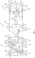
- Fig.1 shows a vehicle combination 10.
- the vehicle combination 10 comprises a towing vehicle 12, which is, for example, a commercial vehicle.
- the towing vehicle 12 is connected to a trailer vehicle 16 of the vehicle combination 10 via a drawbar 14.
- the trailer vehicle 16 can thus be towed by the towing vehicle 12.
- the towing vehicle 12 and the trailer vehicle 16 each comprise several axles 18, each of which has two wheels 20a, 20b.
- the wheels 20a are driven wheels and thus belong to a drive axle 18 and the wheels 20b are non-driven wheels and belong to a non-driven axle 18.
- Non-driven wheels 20b here refer to non-driven wheels.
- Each of the wheels 20a, 20b is equipped with a friction brake 22 in order to brake the wheels 20a, 20b in the event of a braking request.
- At least one of the axles 18 of the towing vehicle 12 is driven by an internal combustion engine or an electric drive, whereby neither an internal combustion engine nor an electric drive is shown for better overview in Fig.1 is shown.
- a request for an increase in speed 27 or a braking request 29 is signaled by an operator of the towing vehicle 12 by varying an accelerator pedal position 23 of an accelerator pedal 24 and by varying a brake pedal position 25 of a brake pedal 26.
- the request for an increase in speed 27 or a braking request 29 is signaled by a Control is generated which controls autonomous operation or driver assistance operation.
- the accelerator pedal 24 is connected to a vehicle control unit 28 and the brake pedal 26 to a brake control unit 32 for signaling purposes.
- the vehicle control unit 28 transmits control signals for controlling the drive (not shown) to a bus (not shown) connected to the vehicle control unit 28.
- the vehicle control unit 28 transmits a requested positive acceleration 31 from the request for an increase in speed 27 and also passes this on to the brake control unit 32 via a connection 34.
- the brake control unit 32 monitors a differential slip between at least one driven wheel 20a and a non-driven wheel 20b, particularly in the case of a requested positive acceleration 31. Wheel speed sensors 21 are provided on the wheels 20a, 20b for this purpose. If a differential slip above a predefined threshold value is detected in the brake control unit 32, this is interpreted as a loss of traction of the towing vehicle 12.
- the brake control unit 32 then generates a signal 33 to reduce the drive torque for the vehicle control unit 28 and sends this to the vehicle control unit 28 via the connection 34.
- an acceleration request 46 is generated and sent on a CAN-ISO 11992-2 bus 30.
- the bus 30 is connected to a trailer brake control unit 48 of the trailer vehicle 16, to which the acceleration request 46 is transmitted.
- An electric drive 52 is also connected via a further bus 50 to the trailer brake control unit 48, which receives the acceleration request 48 via the bus 30.
- the electric drive comprises a battery 54, which is rechargeable and can also be referred to as an accumulator.
- the electric drive 52 comprises two converters 56, which supply electric motors 58 with the energy from the battery 54 in order to generate a positive torque.
- the battery 54, the converters 56 and the electric motors 58 correspond to components 59 of the electric drive 52.
- only one electric motor 58 is provided, which also has only one converter 56 and drives two or more wheels 20b via a differential.
- the electric motors 58 in Fig.1 can also be operated in generator mode or as a generator, so that electrical energy 55 is fed back into the battery 54 via the converter 56.
- the converter 56 of the electric drive 52 is connected to the trailer brake control unit 48 via the further bus 50 in order to receive a control signal 60 from the trailer brake control unit 48, which is generated in the trailer brake control unit 48 depending on the acceleration request 46.
- Control of the converter 56 which takes place depending on the control signal 60, specifies on the one hand whether the electric motors 58 should be operated in generator mode or motor mode and which torque should be used in this case. In the case of operation of the electric motors 58 in motor mode, this is referred to as a positive torque, while the torque, i.e. a value of the torque in generator mode of the electric motors 58, is referred to as a negative torque.
- control signals 60 are only considered here with at least one positive torque value.
- the control signal 60 is sent from the trailer brake control unit 48 to the electric drive 52 via the further bus 50 and, in the present case, two torque values are taken from the control signal 60, with which wheel-specific drive torques are generated.
- the electric drive 52 also sends a status signal 64 to the trailer brake control unit 48 in order to be able to inform the trailer brake control unit 48, for example or among other things, which currently available positive torque or which currently available positive torque change is provided by the electric drive 52 at the current time.
- the currently available torques or torque changes depend, for example, on the current operating state of the electric drive 52.
- the trailer brake control unit 48 is also connected, as is the brake control unit 32 of the towing vehicle 12, to speed sensors 21 in order to monitor a differential slip between at least one driven wheel 20a and a non-driven wheel 20b of the trailer vehicle 16, wherein the control signal 60 can then additionally be determined as a function of the differential slip from the acceleration request 46.
- Fig.2 shows the steps of an embodiment of the method.
- a differential slip 92 is determined.
- sensor signals 94 of a wheel speed sensor 21 on a driven wheel 20a of the towing vehicle 12 and sensor signals 96 of a further wheel speed sensor 21 on a non-driven wheel 20b of the towing vehicle 12 are fed to the determination step 90.
- the differential slip 92 is compared with a threshold value 100 in a step 98 and, if the differential slip 92 exceeds the threshold value 100, a loss of traction 102 is reported and output.
- a signal 33 is output which is transmitted to a vehicle control unit 28 in order to reduce the engine torque of an engine of the towing vehicle 12.
- a command is issued in step 104 in order to then determine or generate an acceleration request 46 in a step 108.
- acceleration requests 110a, 110b from driver control elements 112 and/or driver assistance systems 114 are also supplied.
- the acceleration request 46 is then issued and after a transmission step 118 in which the acceleration request 46 was transmitted to a trailer brake control unit 48, a control signal 60 is generated from the acceleration request 46 in a step 120.
- a bend angle 122 between the towing vehicle 12 and a trailer vehicle 16 and, if necessary, a further bend angle 124 between the trailer vehicle 16 and another trailer vehicle 16 are fed to step 120.
- a state of the trailer vehicle 16 is determined in a step 126 and this state 128 is additionally taken into account when generating the control signal 60.
- the state 128 of the trailer vehicle 16 is determined from the axle load 130 and a mass distribution 132.
- a further differential slip 136 is determined in a step 134 between at least one driven wheel 20a and a non-driven wheel 20b of the trailer vehicle 16. The differential slip 136 is also taken into account when generating the control signal 60 in step 120.
- the generated control signal 60 is then transmitted to an electric drive 52 in a step 140.
- a step 138 depending on the control signal 60, one or more drive torques 139 are generated with one or more electric motors 58 and the connected driven wheels 20a of the trailer vehicle 16.
- the control signal 60 is initially interpreted as a maximum drive torque 142 with the electric drive 52 in step 138 and thus a converter 56 is controlled in a control step 144.
- at least one electric motor 58 is supplied with energy from an energy storage device in a step 148.
- a start value 150, a step size 152, a time interval 154 and a predefined threshold value 156 are fed to step 144.
- the electric motor 58 is controlled such that, starting from the starting value 150, a torque is generated with the motor 58, which increases each time after the expiration of the time interval 154 by an increment 152 up to the maximum drive torque 142, as long as a differential slip 158 of at least two wheels 20a driven by the electric drive 52, which is also fed to step 144, is below the predefined threshold value 156.
- a predefined temporal gradient 160 is fed to the control step 144, so that it is alternatively possible for the electric motor 58 to be continuously increased in accordance with the gradient 160 with respect to the torque generated, starting from the starting value 150, until the maximum drive torque 142 is reached.
- the towing vehicle 12 is assisted by the trailer vehicle 16 in the event of a loss of traction 102 of the trailer vehicle 16.
Landscapes
- Engineering & Computer Science (AREA)
- Mechanical Engineering (AREA)
- Transportation (AREA)
- Automation & Control Theory (AREA)
- Chemical & Material Sciences (AREA)
- Combustion & Propulsion (AREA)
- Regulating Braking Force (AREA)
- Electric Propulsion And Braking For Vehicles (AREA)
Claims (15)
- Procédé d'assistance d'un véhicule tracteur (12) en cas de perte de traction (102) due à un véhicule remorqué (16), comprenant les étapes :- de détermination (90) d'un glissement différentiel (92) entre au moins une roue motrice (20a) et au moins une roue non motrice (20b) du véhicule tracteur (12) au moyen d'un appareil de commande de frein (32) du véhicule tracteur (12), lequel glissement différentiel est supérieur à une valeur seuil prédéfinie (100),- de génération (108) d'une demande d'accélération (46) en fonction du glissement différentiel (92) déterminé dans l'appareil de commande de frein (32) du véhicule tracteur (12),- de transmission (118) de la demande d'accélération (46) à un appareil de commande de frein de remorque (48) du véhicule remorqué (16),- de génération (120) d'un signal de commande (60) pour un entraînement électrique (52) du véhicule remorqué (16) en fonction de la demande d'accélération (46) dans l'appareil de commande de frein de remorque (48),- de transmission (140) d'au moins un signal de commande (60) de l'appareil de commande de frein de remorque (48) à l'au moins un entraînement électrique (52) du véhicule remorqué (16) et- de génération (138) d'au moins un couple d'entraînement (139) au moyen de l'entraînement électrique (52) en fonction du signal de commande (60).
- Procédé selon la revendication 1, dans lequel la transmission (118) de la demande d'accélération (46) à l'appareil de commande de frein de remorque (48) comprend la transmission (118) de la demande d'accélération (46) par l'intermédiaire d'un bus (30) CAN-ISO 11992-2.
- Procédé selon la revendication 1 ou 2, dans lequel la demande d'accélération (46) est déterminée en fonction du glissement différentiel (92) du véhicule tracteur (12) et d'une accélération souhaitée (110a, 110b) par un élément d'actionnement par un conducteur (112) ou un système d'assistance au conducteur (114).
- Procédé selon l'une des revendications précédentes, dans lequel un état de véhicule (128) du véhicule remorqué (16) est déterminé (126) au moyen de l'appareil de commande de frein de remorque (48) et la génération (120) du signal de commande (60) pour l'entraînement électrique (52) du véhicule remorqué (16) est effectuée en outre en fonction de l'état de véhicule (128) du véhicule remorqué (16).
- Procédé selon la revendication 4, dans lequel, lors de la détermination (126) de l'état de véhicule (128), au moins un état de chargement (130, 132) du véhicule remorqué (16) est pris en compte, comprenant en particulier au moins une charge par essieu (130) des essieux (18) du véhicule remorqué (16) et/ou une répartition de masse (132) dans le véhicule remorqué (16).
- Procédé selon l'une des revendications précédentes, dans lequel la génération (120) du signal de commande (60) et/ou de la demande d'accélération (46) est en outre effectuée en fonction d'au moins un angle d'articulation (122, 124), dans lequel un angle d'articulation (122) entre le véhicule tracteur (12) et le véhicule remorqué (16) est déterminé et, dans le cas où le véhicule remorqué (16) est un autre véhicule remorqué (16) qui est attelé à un véhicule remorqué (16), un autre angle d'articulation (124) entre le véhicule remorqué (16) et l'autre véhicule remorqué (16) est déterminé.
- Procédé selon l'une des revendications précédentes, dans lequel la génération (138) du couple d'entraînement (139) au moyen de l'entraînement électrique (52) comprend une commande (144) d'au moins un convertisseur électrique (56) du véhicule remorqué (16) pour alimenter (148) au moins un moteur électrique (58) du véhicule remorqué (16) en énergie (55) à partir d'un accumulateur d'énergie (54) du véhicule remorqué (16).
- Procédé selon l'une des revendications précédentes, dans lequel un glissement différentiel (158) est déterminé entre au moins deux roues (20a) du véhicule remorqué (16) entraînées par l'entraînement électrique (52), en particulier par l'entraînement électrique (52) et
le signal de commande (60) correspond à au moins une valeur de couple maximale (142) ou comprend celle-ci et un couple de commande (146) permettant de générer (138) le couple d'entraînement (139) au moyen de l'entraînement électrique (52) à partir d'une valeur de départ prédéfinie (150) est augmenté progressivement, en particulier avec une largeur de pas (152) prédéfinie et avec un intervalle de temps (154) prédéfini, ou en continu, en particulier avec une pente temporelle (160) prédéfinie, jusqu'à la valeur de couple maximale (142), tant que le glissement différentiel (158) des roues motrices (20a) du véhicule remorqué (16) est inférieur à une autre valeur seuil (156) prédéfinie. - Procédé selon l'une des revendications précédentes, dans lequel la demande d'accélération (46) correspond à un couple d'entraînement maximal (142) à générer au moyen de l'entraînement électrique (52) ou comprend ledit couple d'entraînement maximal et le signal de commande (60) est généré de telle sorte que le couple d'entraînement maximal (142) à générer n'est pas dépassé.
- Procédé selon l'une des revendications précédentes, dans lequel un glissement différentiel (136) du véhicule remorqué (16) entre au moins une roue motrice (20a) et une roue non motrice (20b) du véhicule remorqué (16) est surveillé au moyen de l'appareil de commande de frein de remorque (48) et le signal de commande (60) est déterminé en fonction de ce glissement différentiel (136).
- Procédé selon la revendication 10, dans lequel, dans le véhicule remorqué (16), différentes roues (20) sont commandées par des signaux de commande (60) individuels pour générer (138) un couple d'entraînement (139) et/ou sont freinées individuellement.
- Véhicule tracteur (12) permettant de mettre en oeuvre un procédé selon l'une des revendications précédentes, dans lequel le véhicule tracteur (12) comprend au moins un appareil de commande de frein (32) et est conçu pour déterminer une perte de traction (102) au moyen de l'appareil de commande de frein (32), pour déterminer une demande d'accélération (46) en fonction d'un glissement différentiel (92) conduisant à la perte de traction (102) détectée, et pour transmettre (118) la demande d'accélération (46) à un appareil de commande de frein de remorque (48).
- Véhicule remorqué (16) permettant de mettre en oeuvre un procédé selon l'une des revendications 1 à 11, dans lequel le véhicule remorqué (16) est conçu pour recevoir une demande d'accélération (46) d'un appareil de commande de frein (32) d'un véhicule tracteur (12) au moyen d'un appareil de commande de frein de remorque (48) du véhicule remorqué (16), pour générer, dans l'appareil de commande de frein de remorque (48), un signal de commande (60) permettant de commander un entraînement électrique (52) en fonction de la demande d'accélération (46), et pour générer, au moyen de l'entraînement électrique (52) du véhicule remorqué (16), un couple d'entraînement (139) en fonction du signal de commande (60).
- Attelage (10) constitué d'un véhicule tracteur (12) selon la revendication 12 et d'un véhicule remorqué (16) selon la revendication 13, dans lequel le véhicule remorqué (16) est relié au véhicule tracteur (12) par l'intermédiaire d'un bus (30) CAN-ISO 11992-2.
- Produit de programme informatique comprenant des parties d'un code de programme qui, exécuté sur un appareil de commande de frein (32) d'un véhicule tracteur (12), exécute les étapes du procédé selon l'une des revendications 1 à 11, lesquelles étapes doivent être exécutées par l'appareil de commande de frein (32), et comprenant des parties d'un code de programme qui, exécuté sur un appareil de commande de frein de remorque (48) d'un véhicule remorqué (16), exécute les étapes du procédé selon l'une des revendications 1 à 11, lesquelles étapes doivent être exécutées par l'appareil de commande de frein de remorque (48).
Applications Claiming Priority (2)
| Application Number | Priority Date | Filing Date | Title |
|---|---|---|---|
| DE102019119786.4A DE102019119786A1 (de) | 2019-07-22 | 2019-07-22 | Verfahren zum Unterstützen eines Zugfahrzeugs bei Traktionsverlust |
| PCT/EP2020/069208 WO2021013541A1 (fr) | 2019-07-22 | 2020-07-08 | Procédé pour assister un véhicule tracteur en cas de perte de traction |
Publications (2)
| Publication Number | Publication Date |
|---|---|
| EP4003771A1 EP4003771A1 (fr) | 2022-06-01 |
| EP4003771B1 true EP4003771B1 (fr) | 2024-07-24 |
Family
ID=71607948
Family Applications (1)
| Application Number | Title | Priority Date | Filing Date |
|---|---|---|---|
| EP20739922.1A Active EP4003771B1 (fr) | 2019-07-22 | 2020-07-08 | Méthode d'assistance de traction d'un tracteur tirant une remorque |
Country Status (5)
| Country | Link |
|---|---|
| US (1) | US12377851B2 (fr) |
| EP (1) | EP4003771B1 (fr) |
| CN (1) | CN114007916B (fr) |
| DE (1) | DE102019119786A1 (fr) |
| WO (1) | WO2021013541A1 (fr) |
Families Citing this family (14)
| Publication number | Priority date | Publication date | Assignee | Title |
|---|---|---|---|---|
| US11814098B2 (en) * | 2021-03-11 | 2023-11-14 | GM Global Technology Operations LLC | Methods, systems, and apparatuses for identification and compensation of trailer impacts on steering dynamics for automated driving |
| US12116009B2 (en) * | 2021-03-22 | 2024-10-15 | Waymo Llc | Systems and operations of transfer hubs for autonomous trucking systems |
| DE102021133759A1 (de) | 2021-12-17 | 2023-06-22 | Zf Cv Systems Global Gmbh | Verfahren zum Betreiben eines Anhängerfahrzeugs mit einem elektrischen Antrieb und mit Reibbremsen sowie Anhängerbremssteuergerät und Anhängerfahrzeug zum Ausführen des Verfahrens |
| EP4265494B1 (fr) * | 2022-04-21 | 2025-07-02 | ZF CV Systems Global GmbH | Unité de traitement d'air, système de gestion d'air, système pneumatique et véhicule |
| US12427957B2 (en) * | 2022-04-28 | 2025-09-30 | Bendix Commercial Vehicle Systems Llc | Multi-circuit braking system for brake blending on an electric driveline equipped with pneumatic control |
| KR20250028280A (ko) * | 2022-06-23 | 2025-02-28 | 볼보 트럭 코퍼레이션 | 스윙 아웃 방지를 위한 크루즈 제어 시스템 제어 방법 |
| GB2620183B (en) * | 2022-06-30 | 2024-10-09 | Bamford Excavators Ltd | A method and system for enhanced braking in a tractor unit |
| CN115610556A (zh) * | 2022-10-17 | 2023-01-17 | 山东省交通科学研究院 | 一种探地雷达检测车 |
| DE102023109504A1 (de) * | 2023-04-14 | 2024-10-17 | Zf Cv Systems Global Gmbh | Verfahren zum Betreiben eines Antriebs eines Anhängers sowie ein Anhänger für ein Fahrzeuggespann |
| DE102023121783A1 (de) * | 2023-08-15 | 2025-02-20 | Zf Cv Systems Global Gmbh | Steuern eines Aufliegers mit einer elektrischen Antriebsmaschine |
| DE102023125298A1 (de) * | 2023-09-19 | 2025-03-20 | Zf Cv Systems Global Gmbh | Verfahren für ein Bremsensteuergerät zum Betreiben eines elektrischen Antriebs eines Anhängefahrzeugs, Computerprogramm und/oder computerlesbares Medium, Bremsensteuergerät, Anhängefahrzeug |
| DE102023132374A1 (de) * | 2023-11-21 | 2025-05-22 | Zf Cv Systems Global Gmbh | Verfahren zur Stabilisierung eines Anhängefahrzeugs, Steuereinheit, Anhängefahrzeug und Fahrzeuggespann |
| DE102024111657A1 (de) * | 2024-04-25 | 2025-10-30 | Audi Aktiengesellschaft | Gespann, Zugfahrzeug und Anhänger |
| DE102024205147A1 (de) * | 2024-06-04 | 2025-12-04 | Zf Friedrichshafen Ag | Verfahren zum Betreiben einer Antriebseinrichtung für einen Anhänger |
Family Cites Families (13)
| Publication number | Priority date | Publication date | Assignee | Title |
|---|---|---|---|---|
| DE4133912A1 (de) * | 1991-10-09 | 1993-04-15 | Mannesmann Ag | Fahrzeug mit durch elektromotoren angetriebenen antriebsraedern |
| DE10137148A1 (de) * | 2001-07-30 | 2003-02-13 | Knorr Bremse Systeme | Bremsanlage für Nutzfahrzeuganhänger |
| US8010252B2 (en) * | 2007-10-05 | 2011-08-30 | Ford Global Technologies | Trailer oscillation detection and compensation method for a vehicle and trailer combination |
| US8244445B2 (en) * | 2007-10-30 | 2012-08-14 | Ford Global Technologies, Llc | Stuck vehicle with time and pedal related traction control |
| US8061464B2 (en) * | 2008-04-09 | 2011-11-22 | Ford Global Technologies, Llc | Traction and stability control system and method for a vehicle with mechanically independent front and rear traction wheels |
| DE102009008342B4 (de) * | 2009-02-11 | 2015-09-10 | Knorr-Bremse Systeme für Nutzfahrzeuge GmbH | Steuerungs- und Überwachungsvorrichtung eines Fahrzeugs mit in einer Baueinheit integriertem Reifenüberwachungs-Steuergerät und Brems-Steuergerät |
| DE102015009149A1 (de) * | 2015-07-14 | 2017-01-19 | Günter Löffelmann | LKW und Verfahren zu seinem Betrieb |
| DE102016013054A1 (de) * | 2015-12-09 | 2017-06-14 | Wabco Gmbh | Verfahren zum Einstellen von Bremsdrücken eines Fahrzeugs, Bremsanlage zur Durchführung des Verfahrens sowie Fahrzeug |
| DE102016210343A1 (de) * | 2016-06-10 | 2017-12-14 | Zf Friedrichshafen Ag | Verfahren zum Steuern des Antriebs eines elektrisch angetriebenen Anhängers aufweisend zumindest eine elektrisch angetriebene Achse |
| DE102016213786A1 (de) * | 2016-07-27 | 2018-02-01 | Siemens Aktiengesellschaft | Anhänger, Kraftfahrzeuggespann mit solch einem Anhänger und Verfahren zum Betrieb solch eines Anhängers |
| US10309871B2 (en) * | 2016-09-22 | 2019-06-04 | Ford Global Technologie, Llc | Trailer for measuring operating characteristics of a vehicle |
| EP3315369B1 (fr) * | 2016-10-25 | 2021-03-03 | KNORR-BREMSE Systeme für Nutzfahrzeuge GmbH | Appareil et procédé de commande d'une traction d'un véhicule |
| DE102017210485A1 (de) * | 2017-06-22 | 2018-12-27 | Robert Bosch Gmbh | Verfahren und Vorrichtung zur Traktionsunterstützung eines Fahrzeuggespanns |
-
2019
- 2019-07-22 DE DE102019119786.4A patent/DE102019119786A1/de active Pending
-
2020
- 2020-07-08 EP EP20739922.1A patent/EP4003771B1/fr active Active
- 2020-07-08 WO PCT/EP2020/069208 patent/WO2021013541A1/fr not_active Ceased
- 2020-07-08 CN CN202080044204.9A patent/CN114007916B/zh active Active
-
2022
- 2022-01-18 US US17/577,682 patent/US12377851B2/en active Active
Also Published As
| Publication number | Publication date |
|---|---|
| WO2021013541A1 (fr) | 2021-01-28 |
| US12377851B2 (en) | 2025-08-05 |
| CN114007916B (zh) | 2024-10-01 |
| US20220135041A1 (en) | 2022-05-05 |
| EP4003771A1 (fr) | 2022-06-01 |
| CN114007916A (zh) | 2022-02-01 |
| DE102019119786A1 (de) | 2021-01-28 |
Similar Documents
| Publication | Publication Date | Title |
|---|---|---|
| EP4003771B1 (fr) | Méthode d'assistance de traction d'un tracteur tirant une remorque | |
| EP3906177B1 (fr) | Remorque et dispositif de contrôle de freinage du remorque, procédé et produit de programme informatique | |
| EP2760714B1 (fr) | Système de freinage à régulation de glissement, destiné à des véhicules électriques | |
| EP4126583B1 (fr) | Procédé et dispositif de contrôle d'entraînement électrique d'une remorque | |
| EP4003774B1 (fr) | Procédé et dispositif pour activer un entraînement électrique d'un véhicule tracté | |
| DE102020202477A1 (de) | Sicherheitssystem für einen elektrisch antreibbaren Kraftwagen, Verfahren zum Betreiben eines solchen Sicherheitssystems sowie Kraftwagen | |
| EP4054905B1 (fr) | Méthode et système pour freiner un véhicule utilitaire avec un propulsion électrique | |
| DE102018121439A1 (de) | Anhängerbremssteuergerät sowie Verfahren und Software dafür und Anhängerfahrzeug damit | |
| EP1016572A2 (fr) | Dispositif et procédé de stabilisation d'un attelage de véhicules constitué d'un tracteur et d'une remorque | |
| DE102020212598A1 (de) | Traktionssteuereinrichtung und -Verfahren für vierradgetriebenes Elektrofahrzeug | |
| DE102021204001B4 (de) | Verfahren zur Antriebsregelung eines Anhängers und Antriebsvorrichtung | |
| DE102021121914A1 (de) | Fahrzeugbremssystem und Fahrzeugbremsverfahren | |
| EP3030451A2 (fr) | Procédé de freinage d'un véhicule et véhicule | |
| EP0700822B1 (fr) | Procédé limitant l'angle de pliage entre les parties avant et arrière d'un autobus articulé | |
| WO2023066604A1 (fr) | Dispositif destiné à exciter un entraînement électrique d'un véhicule tracté ainsi que système le comprenant et procédé associé | |
| DE102022116594A1 (de) | Verfahren zum Ansteuern eines elektrischen Antriebs eines Anhängerfahrzeugs sowie Anhängersteuergerät zum Ausführen des Verfahrens | |
| DE102022116596A1 (de) | Anhängersteuergerät zum Ansteuern eines elektrischen Antriebs eines Anhängerfahrzeugs sowie Verfahren zum Ansteuern des elektrischen Antriebs mit dem Anhängersteuergerät | |
| DE102013204913A1 (de) | Rekuperation im Anhängerbetrieb | |
| DE102022100252A1 (de) | Verfahren zum Steuern eines elektrischen Antriebs eines Fahrzeugs sowie System und Gespann zum Ausführen des Verfahrens | |
| DE102021133757A1 (de) | Verfahren zum Bremsen eines Anhängerfahrzeugs mit einem elektrischen Antrieb und Reibbremsen sowie Bremssystem zum Ausführen des Verfahrens | |
| DE102020111402A1 (de) | Notbremsen eines Kraftfahrzeugs mittels eines Doppelkupplungsgetriebes | |
| EP3793857B1 (fr) | Système comprenant un appareil de commande pour un véhicule utilitaire ainsi que procédé servant à faire fonctionner un véhicule utilitaire à l'aide du système | |
| EP4448321B1 (fr) | Procédé de fonctionnement d'un véhicule à remorque avec entraînement électrique et freins à frottement, dispositif de contrôle des freins à remorque et véhicule à remorque à exécuter le procédé | |
| DE102016214747A1 (de) | Zentraler Längsdynamik-Momentkoordinator und Kraftfahrzeugsteuerung | |
| DE102023201427A1 (de) | System und Verfahren zur Koordinierung und Steuerung von Antriebs- und/oder Bremsmomenten und Kraftfahrzeug |
Legal Events
| Date | Code | Title | Description |
|---|---|---|---|
| STAA | Information on the status of an ep patent application or granted ep patent |
Free format text: STATUS: UNKNOWN |
|
| STAA | Information on the status of an ep patent application or granted ep patent |
Free format text: STATUS: THE INTERNATIONAL PUBLICATION HAS BEEN MADE |
|
| PUAI | Public reference made under article 153(3) epc to a published international application that has entered the european phase |
Free format text: ORIGINAL CODE: 0009012 |
|
| STAA | Information on the status of an ep patent application or granted ep patent |
Free format text: STATUS: REQUEST FOR EXAMINATION WAS MADE |
|
| 17P | Request for examination filed |
Effective date: 20220222 |
|
| AK | Designated contracting states |
Kind code of ref document: A1 Designated state(s): AL AT BE BG CH CY CZ DE DK EE ES FI FR GB GR HR HU IE IS IT LI LT LU LV MC MK MT NL NO PL PT RO RS SE SI SK SM TR |
|
| DAV | Request for validation of the european patent (deleted) | ||
| DAX | Request for extension of the european patent (deleted) | ||
| STAA | Information on the status of an ep patent application or granted ep patent |
Free format text: STATUS: EXAMINATION IS IN PROGRESS |
|
| 17Q | First examination report despatched |
Effective date: 20230720 |
|
| GRAP | Despatch of communication of intention to grant a patent |
Free format text: ORIGINAL CODE: EPIDOSNIGR1 |
|
| STAA | Information on the status of an ep patent application or granted ep patent |
Free format text: STATUS: GRANT OF PATENT IS INTENDED |
|
| INTG | Intention to grant announced |
Effective date: 20240418 |
|
| GRAS | Grant fee paid |
Free format text: ORIGINAL CODE: EPIDOSNIGR3 |
|
| GRAA | (expected) grant |
Free format text: ORIGINAL CODE: 0009210 |
|
| STAA | Information on the status of an ep patent application or granted ep patent |
Free format text: STATUS: THE PATENT HAS BEEN GRANTED |
|
| AK | Designated contracting states |
Kind code of ref document: B1 Designated state(s): AL AT BE BG CH CY CZ DE DK EE ES FI FR GB GR HR HU IE IS IT LI LT LU LV MC MK MT NL NO PL PT RO RS SE SI SK SM TR |
|
| REG | Reference to a national code |
Ref country code: GB Ref legal event code: FG4D Free format text: NOT ENGLISH |
|
| REG | Reference to a national code |
Ref country code: CH Ref legal event code: EP |
|
| REG | Reference to a national code |
Ref country code: IE Ref legal event code: FG4D Free format text: LANGUAGE OF EP DOCUMENT: GERMAN Ref country code: DE Ref legal event code: R096 Ref document number: 502020008681 Country of ref document: DE |
|
| REG | Reference to a national code |
Ref country code: LT Ref legal event code: MG9D |
|
| REG | Reference to a national code |
Ref country code: NL Ref legal event code: MP Effective date: 20240724 |
|
| PG25 | Lapsed in a contracting state [announced via postgrant information from national office to epo] |
Ref country code: PT Free format text: LAPSE BECAUSE OF FAILURE TO SUBMIT A TRANSLATION OF THE DESCRIPTION OR TO PAY THE FEE WITHIN THE PRESCRIBED TIME-LIMIT Effective date: 20241125 |
|
| PG25 | Lapsed in a contracting state [announced via postgrant information from national office to epo] |
Ref country code: NL Free format text: LAPSE BECAUSE OF FAILURE TO SUBMIT A TRANSLATION OF THE DESCRIPTION OR TO PAY THE FEE WITHIN THE PRESCRIBED TIME-LIMIT Effective date: 20240724 |
|
| PG25 | Lapsed in a contracting state [announced via postgrant information from national office to epo] |
Ref country code: PT Free format text: LAPSE BECAUSE OF FAILURE TO SUBMIT A TRANSLATION OF THE DESCRIPTION OR TO PAY THE FEE WITHIN THE PRESCRIBED TIME-LIMIT Effective date: 20241125 Ref country code: NL Free format text: LAPSE BECAUSE OF FAILURE TO SUBMIT A TRANSLATION OF THE DESCRIPTION OR TO PAY THE FEE WITHIN THE PRESCRIBED TIME-LIMIT Effective date: 20240724 |
|
| PG25 | Lapsed in a contracting state [announced via postgrant information from national office to epo] |
Ref country code: NO Free format text: LAPSE BECAUSE OF FAILURE TO SUBMIT A TRANSLATION OF THE DESCRIPTION OR TO PAY THE FEE WITHIN THE PRESCRIBED TIME-LIMIT Effective date: 20241024 |
|
| PG25 | Lapsed in a contracting state [announced via postgrant information from national office to epo] |
Ref country code: FI Free format text: LAPSE BECAUSE OF FAILURE TO SUBMIT A TRANSLATION OF THE DESCRIPTION OR TO PAY THE FEE WITHIN THE PRESCRIBED TIME-LIMIT Effective date: 20240724 Ref country code: PL Free format text: LAPSE BECAUSE OF FAILURE TO SUBMIT A TRANSLATION OF THE DESCRIPTION OR TO PAY THE FEE WITHIN THE PRESCRIBED TIME-LIMIT Effective date: 20240724 Ref country code: GR Free format text: LAPSE BECAUSE OF FAILURE TO SUBMIT A TRANSLATION OF THE DESCRIPTION OR TO PAY THE FEE WITHIN THE PRESCRIBED TIME-LIMIT Effective date: 20241025 |
|
| PG25 | Lapsed in a contracting state [announced via postgrant information from national office to epo] |
Ref country code: BG Free format text: LAPSE BECAUSE OF FAILURE TO SUBMIT A TRANSLATION OF THE DESCRIPTION OR TO PAY THE FEE WITHIN THE PRESCRIBED TIME-LIMIT Effective date: 20240724 |
|
| PG25 | Lapsed in a contracting state [announced via postgrant information from national office to epo] |
Ref country code: LV Free format text: LAPSE BECAUSE OF FAILURE TO SUBMIT A TRANSLATION OF THE DESCRIPTION OR TO PAY THE FEE WITHIN THE PRESCRIBED TIME-LIMIT Effective date: 20240724 |
|
| PG25 | Lapsed in a contracting state [announced via postgrant information from national office to epo] |
Ref country code: IS Free format text: LAPSE BECAUSE OF FAILURE TO SUBMIT A TRANSLATION OF THE DESCRIPTION OR TO PAY THE FEE WITHIN THE PRESCRIBED TIME-LIMIT Effective date: 20241124 |
|
| PG25 | Lapsed in a contracting state [announced via postgrant information from national office to epo] |
Ref country code: HR Free format text: LAPSE BECAUSE OF FAILURE TO SUBMIT A TRANSLATION OF THE DESCRIPTION OR TO PAY THE FEE WITHIN THE PRESCRIBED TIME-LIMIT Effective date: 20240724 |
|
| PG25 | Lapsed in a contracting state [announced via postgrant information from national office to epo] |
Ref country code: RS Free format text: LAPSE BECAUSE OF FAILURE TO SUBMIT A TRANSLATION OF THE DESCRIPTION OR TO PAY THE FEE WITHIN THE PRESCRIBED TIME-LIMIT Effective date: 20241024 Ref country code: ES Free format text: LAPSE BECAUSE OF FAILURE TO SUBMIT A TRANSLATION OF THE DESCRIPTION OR TO PAY THE FEE WITHIN THE PRESCRIBED TIME-LIMIT Effective date: 20240724 |
|
| PG25 | Lapsed in a contracting state [announced via postgrant information from national office to epo] |
Ref country code: RS Free format text: LAPSE BECAUSE OF FAILURE TO SUBMIT A TRANSLATION OF THE DESCRIPTION OR TO PAY THE FEE WITHIN THE PRESCRIBED TIME-LIMIT Effective date: 20241024 Ref country code: PL Free format text: LAPSE BECAUSE OF FAILURE TO SUBMIT A TRANSLATION OF THE DESCRIPTION OR TO PAY THE FEE WITHIN THE PRESCRIBED TIME-LIMIT Effective date: 20240724 Ref country code: NO Free format text: LAPSE BECAUSE OF FAILURE TO SUBMIT A TRANSLATION OF THE DESCRIPTION OR TO PAY THE FEE WITHIN THE PRESCRIBED TIME-LIMIT Effective date: 20241024 Ref country code: LV Free format text: LAPSE BECAUSE OF FAILURE TO SUBMIT A TRANSLATION OF THE DESCRIPTION OR TO PAY THE FEE WITHIN THE PRESCRIBED TIME-LIMIT Effective date: 20240724 Ref country code: IS Free format text: LAPSE BECAUSE OF FAILURE TO SUBMIT A TRANSLATION OF THE DESCRIPTION OR TO PAY THE FEE WITHIN THE PRESCRIBED TIME-LIMIT Effective date: 20241124 Ref country code: HR Free format text: LAPSE BECAUSE OF FAILURE TO SUBMIT A TRANSLATION OF THE DESCRIPTION OR TO PAY THE FEE WITHIN THE PRESCRIBED TIME-LIMIT Effective date: 20240724 Ref country code: GR Free format text: LAPSE BECAUSE OF FAILURE TO SUBMIT A TRANSLATION OF THE DESCRIPTION OR TO PAY THE FEE WITHIN THE PRESCRIBED TIME-LIMIT Effective date: 20241025 Ref country code: FI Free format text: LAPSE BECAUSE OF FAILURE TO SUBMIT A TRANSLATION OF THE DESCRIPTION OR TO PAY THE FEE WITHIN THE PRESCRIBED TIME-LIMIT Effective date: 20240724 Ref country code: ES Free format text: LAPSE BECAUSE OF FAILURE TO SUBMIT A TRANSLATION OF THE DESCRIPTION OR TO PAY THE FEE WITHIN THE PRESCRIBED TIME-LIMIT Effective date: 20240724 Ref country code: BG Free format text: LAPSE BECAUSE OF FAILURE TO SUBMIT A TRANSLATION OF THE DESCRIPTION OR TO PAY THE FEE WITHIN THE PRESCRIBED TIME-LIMIT Effective date: 20240724 |
|
| PG25 | Lapsed in a contracting state [announced via postgrant information from national office to epo] |
Ref country code: SM Free format text: LAPSE BECAUSE OF FAILURE TO SUBMIT A TRANSLATION OF THE DESCRIPTION OR TO PAY THE FEE WITHIN THE PRESCRIBED TIME-LIMIT Effective date: 20240724 Ref country code: RO Free format text: LAPSE BECAUSE OF FAILURE TO SUBMIT A TRANSLATION OF THE DESCRIPTION OR TO PAY THE FEE WITHIN THE PRESCRIBED TIME-LIMIT Effective date: 20240724 Ref country code: DK Free format text: LAPSE BECAUSE OF FAILURE TO SUBMIT A TRANSLATION OF THE DESCRIPTION OR TO PAY THE FEE WITHIN THE PRESCRIBED TIME-LIMIT Effective date: 20240724 |
|
| PG25 | Lapsed in a contracting state [announced via postgrant information from national office to epo] |
Ref country code: EE Free format text: LAPSE BECAUSE OF FAILURE TO SUBMIT A TRANSLATION OF THE DESCRIPTION OR TO PAY THE FEE WITHIN THE PRESCRIBED TIME-LIMIT Effective date: 20240724 |
|
| PG25 | Lapsed in a contracting state [announced via postgrant information from national office to epo] |
Ref country code: CZ Free format text: LAPSE BECAUSE OF FAILURE TO SUBMIT A TRANSLATION OF THE DESCRIPTION OR TO PAY THE FEE WITHIN THE PRESCRIBED TIME-LIMIT Effective date: 20240724 |
|
| REG | Reference to a national code |
Ref country code: DE Ref legal event code: R097 Ref document number: 502020008681 Country of ref document: DE |
|
| PG25 | Lapsed in a contracting state [announced via postgrant information from national office to epo] |
Ref country code: SK Free format text: LAPSE BECAUSE OF FAILURE TO SUBMIT A TRANSLATION OF THE DESCRIPTION OR TO PAY THE FEE WITHIN THE PRESCRIBED TIME-LIMIT Effective date: 20240724 Ref country code: IT Free format text: LAPSE BECAUSE OF FAILURE TO SUBMIT A TRANSLATION OF THE DESCRIPTION OR TO PAY THE FEE WITHIN THE PRESCRIBED TIME-LIMIT Effective date: 20240724 |
|
| PLBE | No opposition filed within time limit |
Free format text: ORIGINAL CODE: 0009261 |
|
| STAA | Information on the status of an ep patent application or granted ep patent |
Free format text: STATUS: NO OPPOSITION FILED WITHIN TIME LIMIT |
|
| 26N | No opposition filed |
Effective date: 20250425 |
|
| PGFP | Annual fee paid to national office [announced via postgrant information from national office to epo] |
Ref country code: GB Payment date: 20250529 Year of fee payment: 6 |
|
| PGFP | Annual fee paid to national office [announced via postgrant information from national office to epo] |
Ref country code: FR Payment date: 20250610 Year of fee payment: 6 |
|
| PG25 | Lapsed in a contracting state [announced via postgrant information from national office to epo] |
Ref country code: SE Free format text: LAPSE BECAUSE OF FAILURE TO SUBMIT A TRANSLATION OF THE DESCRIPTION OR TO PAY THE FEE WITHIN THE PRESCRIBED TIME-LIMIT Effective date: 20240724 |
|
| PGFP | Annual fee paid to national office [announced via postgrant information from national office to epo] |
Ref country code: DE Payment date: 20250604 Year of fee payment: 6 |
|
| REG | Reference to a national code |
Ref country code: CH Ref legal event code: H13 Free format text: ST27 STATUS EVENT CODE: U-0-0-H10-H13 (AS PROVIDED BY THE NATIONAL OFFICE) Effective date: 20260224 |
|
| PG25 | Lapsed in a contracting state [announced via postgrant information from national office to epo] |
Ref country code: LU Free format text: LAPSE BECAUSE OF NON-PAYMENT OF DUE FEES Effective date: 20250708 |
|
| REG | Reference to a national code |
Ref country code: BE Ref legal event code: MM Effective date: 20250731 |
|
| PG25 | Lapsed in a contracting state [announced via postgrant information from national office to epo] |
Ref country code: BE Free format text: LAPSE BECAUSE OF NON-PAYMENT OF DUE FEES Effective date: 20250731 |
|
| PG25 | Lapsed in a contracting state [announced via postgrant information from national office to epo] |
Ref country code: CH Free format text: LAPSE BECAUSE OF NON-PAYMENT OF DUE FEES Effective date: 20250731 |