EP4003800B1 - Procede de commande, lors des passages de vitesses, des reseaux d'alimentation electrique d'un vehicule hybride equipe d'une boite de vitesse robotisee, ainsi que dispositif de commande et véhicule - Google Patents
Procede de commande, lors des passages de vitesses, des reseaux d'alimentation electrique d'un vehicule hybride equipe d'une boite de vitesse robotisee, ainsi que dispositif de commande et véhicule Download PDFInfo
- Publication number
- EP4003800B1 EP4003800B1 EP20737191.5A EP20737191A EP4003800B1 EP 4003800 B1 EP4003800 B1 EP 4003800B1 EP 20737191 A EP20737191 A EP 20737191A EP 4003800 B1 EP4003800 B1 EP 4003800B1
- Authority
- EP
- European Patent Office
- Prior art keywords
- voltage
- converter
- network
- motor vehicle
- electrical
- Prior art date
- Legal status (The legal status is an assumption and is not a legal conclusion. Google has not performed a legal analysis and makes no representation as to the accuracy of the status listed.)
- Active
Links
Images
Classifications
-
- B—PERFORMING OPERATIONS; TRANSPORTING
- B60—VEHICLES IN GENERAL
- B60W—CONJOINT CONTROL OF VEHICLE SUB-UNITS OF DIFFERENT TYPE OR DIFFERENT FUNCTION; CONTROL SYSTEMS SPECIALLY ADAPTED FOR HYBRID VEHICLES; ROAD VEHICLE DRIVE CONTROL SYSTEMS FOR PURPOSES NOT RELATED TO THE CONTROL OF A PARTICULAR SUB-UNIT
- B60W20/00—Control systems specially adapted for hybrid vehicles
- B60W20/10—Controlling the power contribution of each of the prime movers to meet required power demand
- B60W20/15—Control strategies specially adapted for achieving a particular effect
-
- B—PERFORMING OPERATIONS; TRANSPORTING
- B60—VEHICLES IN GENERAL
- B60K—ARRANGEMENT OR MOUNTING OF PROPULSION UNITS OR OF TRANSMISSIONS IN VEHICLES; ARRANGEMENT OR MOUNTING OF PLURAL DIVERSE PRIME-MOVERS IN VEHICLES; AUXILIARY DRIVES FOR VEHICLES; INSTRUMENTATION OR DASHBOARDS FOR VEHICLES; ARRANGEMENTS IN CONNECTION WITH COOLING, AIR INTAKE, GAS EXHAUST OR FUEL SUPPLY OF PROPULSION UNITS IN VEHICLES
- B60K6/00—Arrangement or mounting of plural diverse prime-movers for mutual or common propulsion, e.g. hybrid propulsion systems comprising electric motors and internal combustion engines
- B60K6/20—Arrangement or mounting of plural diverse prime-movers for mutual or common propulsion, e.g. hybrid propulsion systems comprising electric motors and internal combustion engines the prime-movers consisting of electric motors and internal combustion engines, e.g. HEVs
- B60K6/42—Arrangement or mounting of plural diverse prime-movers for mutual or common propulsion, e.g. hybrid propulsion systems comprising electric motors and internal combustion engines the prime-movers consisting of electric motors and internal combustion engines, e.g. HEVs characterised by the architecture of the hybrid electric vehicle
- B60K6/44—Series-parallel type
- B60K6/442—Series-parallel switching type
-
- B—PERFORMING OPERATIONS; TRANSPORTING
- B60—VEHICLES IN GENERAL
- B60K—ARRANGEMENT OR MOUNTING OF PROPULSION UNITS OR OF TRANSMISSIONS IN VEHICLES; ARRANGEMENT OR MOUNTING OF PLURAL DIVERSE PRIME-MOVERS IN VEHICLES; AUXILIARY DRIVES FOR VEHICLES; INSTRUMENTATION OR DASHBOARDS FOR VEHICLES; ARRANGEMENTS IN CONNECTION WITH COOLING, AIR INTAKE, GAS EXHAUST OR FUEL SUPPLY OF PROPULSION UNITS IN VEHICLES
- B60K6/00—Arrangement or mounting of plural diverse prime-movers for mutual or common propulsion, e.g. hybrid propulsion systems comprising electric motors and internal combustion engines
- B60K6/20—Arrangement or mounting of plural diverse prime-movers for mutual or common propulsion, e.g. hybrid propulsion systems comprising electric motors and internal combustion engines the prime-movers consisting of electric motors and internal combustion engines, e.g. HEVs
- B60K6/50—Architecture of the driveline characterised by arrangement or kind of transmission units
- B60K6/54—Transmission for changing ratio
- B60K6/547—Transmission for changing ratio the transmission being a stepped gearing
-
- B—PERFORMING OPERATIONS; TRANSPORTING
- B60—VEHICLES IN GENERAL
- B60L—PROPULSION OF ELECTRICALLY-PROPELLED VEHICLES; SUPPLYING ELECTRIC POWER FOR AUXILIARY EQUIPMENT OF ELECTRICALLY-PROPELLED VEHICLES; ELECTRODYNAMIC BRAKE SYSTEMS FOR VEHICLES IN GENERAL; MAGNETIC SUSPENSION OR LEVITATION FOR VEHICLES; MONITORING OPERATING VARIABLES OF ELECTRICALLY-PROPELLED VEHICLES; ELECTRIC SAFETY DEVICES FOR ELECTRICALLY-PROPELLED VEHICLES
- B60L50/00—Electric propulsion with power supplied within the vehicle
- B60L50/10—Electric propulsion with power supplied within the vehicle using propulsion power supplied by engine-driven generators, e.g. generators driven by combustion engines
- B60L50/16—Electric propulsion with power supplied within the vehicle using propulsion power supplied by engine-driven generators, e.g. generators driven by combustion engines with provision for separate direct mechanical propulsion
-
- B—PERFORMING OPERATIONS; TRANSPORTING
- B60—VEHICLES IN GENERAL
- B60L—PROPULSION OF ELECTRICALLY-PROPELLED VEHICLES; SUPPLYING ELECTRIC POWER FOR AUXILIARY EQUIPMENT OF ELECTRICALLY-PROPELLED VEHICLES; ELECTRODYNAMIC BRAKE SYSTEMS FOR VEHICLES IN GENERAL; MAGNETIC SUSPENSION OR LEVITATION FOR VEHICLES; MONITORING OPERATING VARIABLES OF ELECTRICALLY-PROPELLED VEHICLES; ELECTRIC SAFETY DEVICES FOR ELECTRICALLY-PROPELLED VEHICLES
- B60L50/00—Electric propulsion with power supplied within the vehicle
- B60L50/50—Electric propulsion with power supplied within the vehicle using propulsion power supplied by batteries or fuel cells
- B60L50/60—Electric propulsion with power supplied within the vehicle using propulsion power supplied by batteries or fuel cells using power supplied by batteries
- B60L50/61—Electric propulsion with power supplied within the vehicle using propulsion power supplied by batteries or fuel cells using power supplied by batteries by batteries charged by engine-driven generators, e.g. series hybrid electric vehicles
-
- B—PERFORMING OPERATIONS; TRANSPORTING
- B60—VEHICLES IN GENERAL
- B60L—PROPULSION OF ELECTRICALLY-PROPELLED VEHICLES; SUPPLYING ELECTRIC POWER FOR AUXILIARY EQUIPMENT OF ELECTRICALLY-PROPELLED VEHICLES; ELECTRODYNAMIC BRAKE SYSTEMS FOR VEHICLES IN GENERAL; MAGNETIC SUSPENSION OR LEVITATION FOR VEHICLES; MONITORING OPERATING VARIABLES OF ELECTRICALLY-PROPELLED VEHICLES; ELECTRIC SAFETY DEVICES FOR ELECTRICALLY-PROPELLED VEHICLES
- B60L58/00—Methods or circuit arrangements for monitoring or controlling batteries or fuel cells, specially adapted for electric vehicles
- B60L58/10—Methods or circuit arrangements for monitoring or controlling batteries or fuel cells, specially adapted for electric vehicles for monitoring or controlling batteries
- B60L58/18—Methods or circuit arrangements for monitoring or controlling batteries or fuel cells, specially adapted for electric vehicles for monitoring or controlling batteries of two or more battery modules
- B60L58/20—Methods or circuit arrangements for monitoring or controlling batteries or fuel cells, specially adapted for electric vehicles for monitoring or controlling batteries of two or more battery modules having different nominal voltages
-
- B—PERFORMING OPERATIONS; TRANSPORTING
- B60—VEHICLES IN GENERAL
- B60R—VEHICLES, VEHICLE FITTINGS, OR VEHICLE PARTS, NOT OTHERWISE PROVIDED FOR
- B60R16/00—Electric or fluid circuits specially adapted for vehicles and not otherwise provided for; Arrangement of elements of electric or fluid circuits specially adapted for vehicles and not otherwise provided for
- B60R16/02—Electric or fluid circuits specially adapted for vehicles and not otherwise provided for; Arrangement of elements of electric or fluid circuits specially adapted for vehicles and not otherwise provided for electric constitutive elements
- B60R16/03—Electric or fluid circuits specially adapted for vehicles and not otherwise provided for; Arrangement of elements of electric or fluid circuits specially adapted for vehicles and not otherwise provided for electric constitutive elements for supply of electrical power to vehicle subsystems or for
-
- H—ELECTRICITY
- H02—GENERATION; CONVERSION OR DISTRIBUTION OF ELECTRIC POWER
- H02J—ELECTRIC POWER NETWORKS; CIRCUIT ARRANGEMENTS OR SYSTEMS FOR SUPPLYING OR DISTRIBUTING ELECTRIC POWER; SYSTEMS FOR STORING ELECTRIC ENERGY
- H02J7/00—Circuit arrangements for charging or discharging batteries or for supplying loads from batteries
- H02J7/14—Circuit arrangements for charging or discharging batteries or for supplying loads from batteries for charging batteries from dynamo-electric generators driven at varying speed, e.g. on vehicle
- H02J7/1423—Circuit arrangements for charging or discharging batteries or for supplying loads from batteries for charging batteries from dynamo-electric generators driven at varying speed, e.g. on vehicle with multiple batteries
-
- H—ELECTRICITY
- H02—GENERATION; CONVERSION OR DISTRIBUTION OF ELECTRIC POWER
- H02J—ELECTRIC POWER NETWORKS; CIRCUIT ARRANGEMENTS OR SYSTEMS FOR SUPPLYING OR DISTRIBUTING ELECTRIC POWER; SYSTEMS FOR STORING ELECTRIC ENERGY
- H02J7/00—Circuit arrangements for charging or discharging batteries or for supplying loads from batteries
- H02J7/34—Parallel operation in networks using both storage and other DC sources, e.g. providing buffering
- H02J7/342—The other DC source being a battery actively interacting with the first one, i.e. battery to battery charging
-
- B—PERFORMING OPERATIONS; TRANSPORTING
- B60—VEHICLES IN GENERAL
- B60L—PROPULSION OF ELECTRICALLY-PROPELLED VEHICLES; SUPPLYING ELECTRIC POWER FOR AUXILIARY EQUIPMENT OF ELECTRICALLY-PROPELLED VEHICLES; ELECTRODYNAMIC BRAKE SYSTEMS FOR VEHICLES IN GENERAL; MAGNETIC SUSPENSION OR LEVITATION FOR VEHICLES; MONITORING OPERATING VARIABLES OF ELECTRICALLY-PROPELLED VEHICLES; ELECTRIC SAFETY DEVICES FOR ELECTRICALLY-PROPELLED VEHICLES
- B60L1/00—Supplying electric power to auxiliary equipment of vehicles
-
- B—PERFORMING OPERATIONS; TRANSPORTING
- B60—VEHICLES IN GENERAL
- B60L—PROPULSION OF ELECTRICALLY-PROPELLED VEHICLES; SUPPLYING ELECTRIC POWER FOR AUXILIARY EQUIPMENT OF ELECTRICALLY-PROPELLED VEHICLES; ELECTRODYNAMIC BRAKE SYSTEMS FOR VEHICLES IN GENERAL; MAGNETIC SUSPENSION OR LEVITATION FOR VEHICLES; MONITORING OPERATING VARIABLES OF ELECTRICALLY-PROPELLED VEHICLES; ELECTRIC SAFETY DEVICES FOR ELECTRICALLY-PROPELLED VEHICLES
- B60L2210/00—Converter types
- B60L2210/40—DC to AC converters
-
- B—PERFORMING OPERATIONS; TRANSPORTING
- B60—VEHICLES IN GENERAL
- B60L—PROPULSION OF ELECTRICALLY-PROPELLED VEHICLES; SUPPLYING ELECTRIC POWER FOR AUXILIARY EQUIPMENT OF ELECTRICALLY-PROPELLED VEHICLES; ELECTRODYNAMIC BRAKE SYSTEMS FOR VEHICLES IN GENERAL; MAGNETIC SUSPENSION OR LEVITATION FOR VEHICLES; MONITORING OPERATING VARIABLES OF ELECTRICALLY-PROPELLED VEHICLES; ELECTRIC SAFETY DEVICES FOR ELECTRICALLY-PROPELLED VEHICLES
- B60L2240/00—Control parameters of input or output; Target parameters
- B60L2240/40—Drive Train control parameters
- B60L2240/52—Drive Train control parameters related to converters
- B60L2240/527—Voltage
-
- B—PERFORMING OPERATIONS; TRANSPORTING
- B60—VEHICLES IN GENERAL
- B60L—PROPULSION OF ELECTRICALLY-PROPELLED VEHICLES; SUPPLYING ELECTRIC POWER FOR AUXILIARY EQUIPMENT OF ELECTRICALLY-PROPELLED VEHICLES; ELECTRODYNAMIC BRAKE SYSTEMS FOR VEHICLES IN GENERAL; MAGNETIC SUSPENSION OR LEVITATION FOR VEHICLES; MONITORING OPERATING VARIABLES OF ELECTRICALLY-PROPELLED VEHICLES; ELECTRIC SAFETY DEVICES FOR ELECTRICALLY-PROPELLED VEHICLES
- B60L2250/00—Driver interactions
- B60L2250/24—Driver interactions by lever actuation
-
- B—PERFORMING OPERATIONS; TRANSPORTING
- B60—VEHICLES IN GENERAL
- B60W—CONJOINT CONTROL OF VEHICLE SUB-UNITS OF DIFFERENT TYPE OR DIFFERENT FUNCTION; CONTROL SYSTEMS SPECIALLY ADAPTED FOR HYBRID VEHICLES; ROAD VEHICLE DRIVE CONTROL SYSTEMS FOR PURPOSES NOT RELATED TO THE CONTROL OF A PARTICULAR SUB-UNIT
- B60W2510/00—Input parameters relating to a particular sub-units
- B60W2510/10—Change speed gearings
-
- B—PERFORMING OPERATIONS; TRANSPORTING
- B60—VEHICLES IN GENERAL
- B60W—CONJOINT CONTROL OF VEHICLE SUB-UNITS OF DIFFERENT TYPE OR DIFFERENT FUNCTION; CONTROL SYSTEMS SPECIALLY ADAPTED FOR HYBRID VEHICLES; ROAD VEHICLE DRIVE CONTROL SYSTEMS FOR PURPOSES NOT RELATED TO THE CONTROL OF A PARTICULAR SUB-UNIT
- B60W2510/00—Input parameters relating to a particular sub-units
- B60W2510/30—Auxiliary equipments
- B60W2510/305—Power absorbed by auxiliaries
-
- B—PERFORMING OPERATIONS; TRANSPORTING
- B60—VEHICLES IN GENERAL
- B60W—CONJOINT CONTROL OF VEHICLE SUB-UNITS OF DIFFERENT TYPE OR DIFFERENT FUNCTION; CONTROL SYSTEMS SPECIALLY ADAPTED FOR HYBRID VEHICLES; ROAD VEHICLE DRIVE CONTROL SYSTEMS FOR PURPOSES NOT RELATED TO THE CONTROL OF A PARTICULAR SUB-UNIT
- B60W2710/00—Output or target parameters relating to a particular sub-units
- B60W2710/30—Auxiliary equipments
- B60W2710/305—Auxiliary equipments target power to auxiliaries
-
- B—PERFORMING OPERATIONS; TRANSPORTING
- B60—VEHICLES IN GENERAL
- B60W—CONJOINT CONTROL OF VEHICLE SUB-UNITS OF DIFFERENT TYPE OR DIFFERENT FUNCTION; CONTROL SYSTEMS SPECIALLY ADAPTED FOR HYBRID VEHICLES; ROAD VEHICLE DRIVE CONTROL SYSTEMS FOR PURPOSES NOT RELATED TO THE CONTROL OF A PARTICULAR SUB-UNIT
- B60W30/00—Purposes of road vehicle drive control systems not related to the control of a particular sub-unit, e.g. of systems using conjoint control of vehicle sub-units
- B60W30/18—Propelling the vehicle
- B60W30/19—Improvement of gear change, e.g. by synchronisation or smoothing gear shift
-
- H—ELECTRICITY
- H02—GENERATION; CONVERSION OR DISTRIBUTION OF ELECTRIC POWER
- H02J—ELECTRIC POWER NETWORKS; CIRCUIT ARRANGEMENTS OR SYSTEMS FOR SUPPLYING OR DISTRIBUTING ELECTRIC POWER; SYSTEMS FOR STORING ELECTRIC ENERGY
- H02J2105/00—Networks for supplying or distributing electric power characterised by their spatial reach or by the load
- H02J2105/30—Networks for supplying or distributing electric power characterised by their spatial reach or by the load the load networks being external to vehicles, i.e. exchanging power with vehicles
- H02J2105/33—Networks for supplying or distributing electric power characterised by their spatial reach or by the load the load networks being external to vehicles, i.e. exchanging power with vehicles exchanging power with road vehicles
- H02J2105/37—Networks for supplying or distributing electric power characterised by their spatial reach or by the load the load networks being external to vehicles, i.e. exchanging power with vehicles exchanging power with road vehicles exchanging power with electric vehicles [EV] or with hybrid electric vehicles [HEV]
-
- Y—GENERAL TAGGING OF NEW TECHNOLOGICAL DEVELOPMENTS; GENERAL TAGGING OF CROSS-SECTIONAL TECHNOLOGIES SPANNING OVER SEVERAL SECTIONS OF THE IPC; TECHNICAL SUBJECTS COVERED BY FORMER USPC CROSS-REFERENCE ART COLLECTIONS [XRACs] AND DIGESTS
- Y02—TECHNOLOGIES OR APPLICATIONS FOR MITIGATION OR ADAPTATION AGAINST CLIMATE CHANGE
- Y02T—CLIMATE CHANGE MITIGATION TECHNOLOGIES RELATED TO TRANSPORTATION
- Y02T10/00—Road transport of goods or passengers
- Y02T10/60—Other road transportation technologies with climate change mitigation effect
- Y02T10/62—Hybrid vehicles
-
- Y—GENERAL TAGGING OF NEW TECHNOLOGICAL DEVELOPMENTS; GENERAL TAGGING OF CROSS-SECTIONAL TECHNOLOGIES SPANNING OVER SEVERAL SECTIONS OF THE IPC; TECHNICAL SUBJECTS COVERED BY FORMER USPC CROSS-REFERENCE ART COLLECTIONS [XRACs] AND DIGESTS
- Y02—TECHNOLOGIES OR APPLICATIONS FOR MITIGATION OR ADAPTATION AGAINST CLIMATE CHANGE
- Y02T—CLIMATE CHANGE MITIGATION TECHNOLOGIES RELATED TO TRANSPORTATION
- Y02T10/00—Road transport of goods or passengers
- Y02T10/60—Other road transportation technologies with climate change mitigation effect
- Y02T10/70—Energy storage systems for electromobility, e.g. batteries
-
- Y—GENERAL TAGGING OF NEW TECHNOLOGICAL DEVELOPMENTS; GENERAL TAGGING OF CROSS-SECTIONAL TECHNOLOGIES SPANNING OVER SEVERAL SECTIONS OF THE IPC; TECHNICAL SUBJECTS COVERED BY FORMER USPC CROSS-REFERENCE ART COLLECTIONS [XRACs] AND DIGESTS
- Y02—TECHNOLOGIES OR APPLICATIONS FOR MITIGATION OR ADAPTATION AGAINST CLIMATE CHANGE
- Y02T—CLIMATE CHANGE MITIGATION TECHNOLOGIES RELATED TO TRANSPORTATION
- Y02T10/00—Road transport of goods or passengers
- Y02T10/60—Other road transportation technologies with climate change mitigation effect
- Y02T10/7072—Electromobility specific charging systems or methods for batteries, ultracapacitors, supercapacitors or double-layer capacitors
-
- Y—GENERAL TAGGING OF NEW TECHNOLOGICAL DEVELOPMENTS; GENERAL TAGGING OF CROSS-SECTIONAL TECHNOLOGIES SPANNING OVER SEVERAL SECTIONS OF THE IPC; TECHNICAL SUBJECTS COVERED BY FORMER USPC CROSS-REFERENCE ART COLLECTIONS [XRACs] AND DIGESTS
- Y02—TECHNOLOGIES OR APPLICATIONS FOR MITIGATION OR ADAPTATION AGAINST CLIMATE CHANGE
- Y02T—CLIMATE CHANGE MITIGATION TECHNOLOGIES RELATED TO TRANSPORTATION
- Y02T10/00—Road transport of goods or passengers
- Y02T10/60—Other road transportation technologies with climate change mitigation effect
- Y02T10/72—Electric energy management in electromobility
Definitions
- the present invention relates to a power supply assembly for a hybrid motor vehicle and a method for regulating, during gear changes, the power and voltage of the low-voltage network of a hybrid vehicle equipped with a robotic gearbox, also called a hybrid transmission.
- the hybrid powertrain is composed of a thermal engine connected to a first gearbox input shaft which can transmit its torque to the wheels on different transmission ratios, a first electrical machine connected to a second input shaft thereof, and a second electrical machine, called a high-voltage alternator-starter, abbreviated HSG, connected alternately to the first or second input shaft of the gearbox, which can act as a generator and as a receiver of electrical energy.
- a thermal engine connected to a first gearbox input shaft which can transmit its torque to the wheels on different transmission ratios
- a first electrical machine connected to a second input shaft thereof
- a second electrical machine called a high-voltage alternator-starter, abbreviated HSG
- the publication WO 2014/207332 describes a hybrid transmission of this type, having several electric, thermal and hybrid ratios, where the torques of the thermal engine and at least one electric machine are added towards the wheels.
- the thermal torque is transmitted to the wheels in a "thermal" transmission ratio, and that of the torque of the main electric machine in an "electric" ratio.
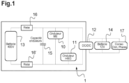
- the power supply assembly of such a hybrid vehicle comprises an electric accumulator battery 13, the first electric machine, not shown, associated with a first inverter 10, and the HSG, not shown, associated with a second inverter 11.
- the two inverters 10, 11 are mounted in parallel with each other, in parallel with capacitors 15 called inverter capacitors 15, and in parallel with the direct-direct converter, abbreviated DCDC 12, capable of supplying energy, from the high voltage network to the low voltage on-board network 17, also called 12V network, powered by a battery 14.
- DCDC 12 direct-direct converter
- the transmission between the thermal engine and the wheels is interrupted.
- the HSG torque is then controlled to synchronize the thermal engine to its new gear, with the main engine providing torque to the wheel.
- the vehicle's electrical architecture particularly the power available from the main electric engine, limits its contribution during thermal gear changes. If the thermal torque interruption is poorly compensated, the driver and passengers of the vehicle feel these changes, like those of a robotized gearbox with torque break. It is therefore desirable to smooth out the torque break felt by the driver and vehicle users during gear changes.
- the document solution FR3051419 consists of increasing the supply voltage of the inverter, to increase the power.
- the electric machine can provide a power of approximately 70kW and the high voltage alternator-starter (abbreviated HSG), operating as an electric generator, a power of approximately 50kW. Also, during this gear change, to increase the supply voltage of the inverter, the battery relays 16, 16' are opened so as to increase the voltage at the terminals of the capacity of the inverters 15.
- HSG high voltage alternator-starter
- the electric machine provides the wheel with exactly the power that the HSG provides to the high-voltage network, the thermal engine maintaining the HSG speed.
- Opening the battery relays is the only simple solution to increase the voltage on the network because otherwise the battery would absorb all the power supplied by the HSG and it would then be impossible to increase the achievable powers.
- the electric machine is not the only device consuming energy from the high-voltage network.
- the on-board network 17 is powered by a 12-volt battery 14.
- a DC/DC converter takes energy from the 400V battery of the high-voltage network and sends it to the low-voltage battery 14.
- the principle of the DC/DC converter is to regulate the voltage of the 12V on-board network to an adjustable setpoint, generally set at 13.5V.
- the HSG therefore supplies energy to the electric machine and the DC/DC which continues to regulate the voltage of the on-board network 17.
- the problem that arises is that in the event of a variation in consumption of the on-board network 17, for example a rotation of the steering wheel using the power steering, the current draw naturally reduces the voltage of the on-board network 17, which triggers a current injection by the DC/DC so as to maintain the voltage at 13.5V.
- the energy thus drawn from the high-voltage (HV) network poses two problems. The first is that this energy is no longer available for the electric machine, which must be taken into account in the power to be supplied to the electric machine during the gear change. The second is that this rapid current draw generates disturbances in the voltage regulation of the HV network, which is carried out by the HSG during this gear change phase.
- the low-voltage network varies.
- the process thus forces the DCDC to provide power beyond a certain threshold, knowing that the voltage can vary while remaining above the set voltage of a low-voltage network, frequently 13.5V. This protects against voltage drops in the on-board network and, for example, the computer restarts that they could cause.
- the second calculation step involves adding the input power with the said correction value.
- the minimum value can be obtained relatively simply.
- the said correction value is between 1kW and 5kW, for example substantially equal to 2kW.
- the voltage on the low-voltage network can remain sufficiently high to ensure the proper functioning of low-voltage equipment without risk of damaging it.
- the invention also relates to a control device according to claim 4.
- the invention also relates to a hybrid motor vehicle according to claim 5.
- a hybrid motor vehicle comprises a heat engine, an electric machine, a high voltage alternator-starter (abbreviated HSG), a power supply assembly as described previously with reference to the Figure 1 , and means for controlling the direct-direct converter 12, also called DCDC 12.
- HSG high voltage alternator-starter
- DCDC direct-direct converter
- the control means of the DC-DC converter 12 are intended to ensure that sufficient power and sufficient current are supplied from the HSG to the DCDC 12, so that the low-voltage network is always correctly supplied.
- the hybrid motor vehicle also includes means implementing a method for optimized control of the torque available on a hybrid vehicle during gear changes.
- the control means are adapted to implement a control method 20.
- the control method comprises a first step 21 of detecting a change of speed on said gearbox or an open battery relay mode. This detection is for example carried out by receiving a digital signal from the robotic gearbox.
- the method implements a step 22 of acquiring the voltage and current values at the terminals of the DC-DC converter 12.
- the information signals typically include the voltage and current values at its terminals, or any other information allowing them to be determined.
- a first calculation step 23 of the input power of the DC-DC converter 12 is implemented as a function of the acquired voltage and current values.
- a person skilled in the art is able to calculate the input power, in other words the power consumed on the high-voltage network 1, and its output power, in other words the power injected into the low-voltage network 14. It is known that, apart from efficiency, these two powers are equal.
- a second calculation step 24 is then carried out for a minimum power value as a function of said input power and a correction value.
- the minimum power corresponds to the input power at the moment when the speed change or open relay mode is detected, to which the correction value is added.
- This correction value corresponds to a margin power to ensure that the low-voltage network voltage 14 remains above 13.5V.
- This margin power is generally between 1kW and 5kW, for example 2kW.
- the effect of this increase in power is that the voltage of the on-board network 17 will increase, but this is not problematic because the constraints of the on-board network 17 are less with regard to voltage increases.
- the on-board network 17 can generally tolerate up to a voltage of 18V.
- the voltage will remain stable at around 15.5V due to the excess power injected with the margin of 2kW. If a current draw occurs, for example following the activation of the power steering for example which consumes approximately 1.2kW, then the power taken from the high voltage network 1 by the DCDC 12 will not vary but the voltage of the on-board network will drop to 14.3V. The voltage is always maintained above 13.5V ensuring the robustness of all consumers of the on-board network 17.
Landscapes
- Engineering & Computer Science (AREA)
- Mechanical Engineering (AREA)
- Transportation (AREA)
- Power Engineering (AREA)
- Life Sciences & Earth Sciences (AREA)
- Sustainable Development (AREA)
- Sustainable Energy (AREA)
- Chemical & Material Sciences (AREA)
- Combustion & Propulsion (AREA)
- Automation & Control Theory (AREA)
- Electric Propulsion And Braking For Vehicles (AREA)
- Hybrid Electric Vehicles (AREA)
Description
- La présente invention concerne un ensemble d'alimentation d'un véhicule automobile hybride et un procédé pour réguler, lors des passages de vitesses, la puissance et la tension du réseau basse tension d'un véhicule hybride équipé d'une boite de vitesse robotisée, aussi appelée transmission hybride.
- Plus précisément, elle a pour objet un procédé de lissage de la tension électrique du réseau électrique haute tension et du réseau électrique basse tension d'un véhicule automobile hybride, tel que représenté en
figure 1 , lorsqu'un contrôle du couple est effectué pendant les changements de rapports d'un groupe motopropulseur à transmission hybride. - Le groupe motopropulseur hybride est composé d'un moteur thermique relié à un premier arbre d'entrée de boîte de vitesses qui peut transmettre son couple aux roues sur différents rapports de transmission, d'une première machine électrique reliée à un deuxième arbre d'entrée de celle-ci, et d'une deuxième machine électrique, nommée alterno-démarreur haute tension, abrégé HSG, reliée alternativement au premier ou au deuxième arbre d'entrée de la boîte, qui peut agir comme générateur et comme récepteur d'énergie électrique.
- La publication
WO 2014/207332 décrit une transmission hybride de ce type, disposant de plusieurs rapports électriques, thermiques et hybrides, où les couples du moteur thermique et d'au moins une machine électrique s'additionnent en direction des roues. Le couple d'origine thermique est transmis aux roues sur un rapport de transmission « thermique », et celle du couple de la machine électrique principale sur un rapport « électrique ». - En référence à la
figure 1 , l'ensemble d'alimentation d'un tel véhicule hybride comprend une batterie d'accumulateurs électriques 13, la première machine électrique, non représentée, associée à un premier onduleur 10, et le HSG, non représenté, associé à un deuxième onduleur 11. Les deux onduleurs 10,11 sont montés en parallèle l'un de l'autre, en parallèle de capacités 15 dites capacités d'onduleurs 15, et en parallèle du convertisseur continu-continu, abrégé DCDC 12, apte à fournir l'énergie, depuis le réseau haute tension vers le réseau de bord basse tension 17, aussi dit réseau 12V, alimenté par une batterie 14. - Lors de changements de rapport de transmission thermique en mode hybride, la transmission entre le moteur thermique et les roues est interrompue. Le couple du HSG est alors piloté pour synchroniser le moteur thermique sur son nouveau rapport, la machine principale fournissant du couple à la roue. Dans la pratique, l'architecture électrique du véhicule, en particulier la puissance disponible sur la machine électrique principale, limite l'apport de celle-ci pendant les changements de rapport thermique. Si l'interruption du couple thermique est peu compensée, le conducteur et les passagers du véhicule ressentent ces passages, comme ceux d'une boîte de vitesse robotisée à rupture de couple. Il est donc souhaitable de parvenir à estomper la rupture de couple ressentie par le conducteur et les usagers du véhicule, pendant les passages de vitesses.
- Une diminution du couple disponible autour du passage répond en théorie à ce problème. Mais, une telle mesure est inacceptable, pour son impact négatif sur les performances.
- Pour résoudre ce problème, on connait le document
FR3051419 - La solution du document
FR3051419 - A 450V d'alimentation, la machine électrique peut fournir une puissance de sensiblement 70kW et l'alterno-démarreur haute tension (abrégé HSG), fonctionnant en tant que générateur électrique, une puissance d'environ 50kW. Aussi, pendant ce changement de rapport, pour augmenter la tension d'alimentation de l'onduleur, les relais batterie 16, 16' sont ouverts de manière à faire monter la tension aux bornes de la capacité des onduleurs 15.
- Ainsi, pendant le changement de rapport, la boite de vitesse fonctionnant selon un mode de type hybride série, la machine électrique fournit à la roue exactement la puissance que fournit le HSG au réseau haute tension, le moteur thermique maintenant le régime du HSG.
- Ouvrir les relais batteries est la seule solution simple pour augmenter la tension sur le réseau car autrement la batterie absorberait toute la puissance fournie par le HSG et il serait alors impossible d'augmenter les puissances réalisables.
- Toutefois la machine électrique n'est pas le seul dispositif consommateur d'énergie du réseau haute-tension. Sur un véhicule électrique, ou hybride disposant d'une batterie de tension suffisante, le réseau de bord 17 est alimenté par une batterie 14 de 12 Volts. À cet effet, un convertisseur DC/DC prélève de l'énergie à la batterie 400V du réseau haute-tension pour l'envoyer vers la batterie 14 basse-tension.
- Le principe du convertisseur DC/DC est de réguler la tension du réseau de bord 12V à une consigne réglable, généralement réglée à 13.5V.
- Le HSG alimente donc en énergie la machine électrique et le DC/DC qui continue à réguler la tension du réseau de bord 17.
- Le problème qui se pose est alors qu'en cas de variation de consommation du réseau de bord 17, par exemple une rotation du volant faisant appel à la direction assistée, l'appel de courant fait naturellement diminuer la tension du réseau de bord 17 ce qui déclenche une injection de courant par le DC/DC de manière à maintenir la tension à 13.5V.
- L'énergie ainsi prélevée sur le réseau haute-tension (HT) pose deux problèmes. Le premier est que cette énergie n'est plus disponible pour la machine électrique dont il faut en tenir compte dans la puissance à fournir à la machine électrique pendant le changement de rapport. Le second est que cet appel de courant rapide génère des perturbations sur la régulation de tension du réseau HT qui est effectuée par le HSG pendant cette phase de changement de rapport.
- Aussi, il existe le besoin d'une solution pour résoudre les problèmes énoncés précédemment.
- À cet effet on propose un procédé de commande d'un ensemble électrique pour un véhicule automobile hybride comprenant un boitier de vitesse à transmission hybride, un réseau électrique haute tension comprenant une batterie d'accumulateurs électriques, un alterno-démarreur haute tension associé à un onduleur, une machine électrique associée à un autre onduleur, le véhicule automobile hybride comprenant en outre un réseau électrique basse tension, et un convertisseur continu-continu apte à alimenter, depuis le réseau haute tension, le réseau électrique basse tension ;
le procédé comprenant : - Une étape de détection d'un changement de mode ou de vitesse sur ledit boitier de vitesse, nécessitant l'ouverture des relais batterie ;
- Lorsqu'un tel changement de mode ou de vitesse est détecté, une étape d'acquisition des valeurs de tension et de courant aux bornes du convertisseur continu-continu ;
- Une première étape de calcul de la puissance d'entrée du convertisseur continu-continu en fonction des valeurs de tensions et de courant acquises ;
- Une deuxième étape de calcul d'une valeur de puissance minimale en fonction de ladite puissance d'entrée et d'une valeur de correction ;
- Une étape de commande du convertisseur continu-continu de sorte à fournir en sortie ladite puissance minimale calculée.
- Ainsi au lieu d'avoir des variations de tension sur le réseau haute tension, on fait varier le réseau basse tension. Le procédé force ainsi le DCDC à fournir une puissance au-delà d'un certain seuil, en sachant que la tension pourra varier en restant au-dessus de la tension de consigne d'un réseau basse-tension, fréquemment 13.5V. Ainsi, on reste protégé contre les chutes de tension du réseau de bord et, par exemple, des redémarrages de calculateurs qu'elles pourraient provoquer.
- En particulier la deuxième étape de calcul comprend l'addition de la puissance d'entrée avec ladite valeur de correction. Ainsi, on peut obtenir la valeur minimale de manière relativement simple.
- En particulier, ladite valeur de correction est comprise entre 1kW et 5kW, par exemple sensiblement égale à 2kW. Ainsi la tension sur le réseau basse-tension peut rester suffisamment élevé pour assurer le bon fonctionnement des équipements basse tension sans risque de les endommager.
- L'invention concerne aussi un dispositif de commande selon la revendication 4.
- L'invention concerne aussi un véhicule automobile hybride selon la revendication 5.
- D'autres particularités et avantages de l'invention ressortiront à la lecture de la description faite ci-après d'un mode de réalisation particulier de l'invention, donné à titre indicatif mais non limitatif, en référence aux dessins annexés sur lesquels :
- [
Fig. 1 ] est une vue schématique d'un ensemble électrique d'un véhicule automobile hybride selon l'invention ; et - [
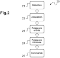
Fig. 2 ] est un organigramme du procédé selon le mode de réalisation de l'invention. - Les
figures 1 et2 se rapportant à un même mode de réalisation de l'invention, elles seront commentées simultanément. - Un véhicule automobile hybride comprend un moteur thermique, une machine électrique, un alterno-démarreur haute tension (abrégé HSG), un ensemble d'alimentation tel que décrit précédemment en référence à la
figure 1 , et des moyens de commande du convertisseur continu-continu 12, aussi appelé DCDC 12. - Les moyens de commande du convertisseur continu-continu 12 sont destinés à s'assurer qu'une puissance suffisante et un courant suffisant soient fournis depuis le HSG au DCDC 12, de sorte que le réseau basse-tension soit toujours correctement alimenté.
- Le véhicule automobile hybride comprend aussi des moyens mettant en œuvre un procédé de contrôle optimisé du couple disponible sur un véhicule hybride pendant les passages de vitesses.
- Les moyens de commande sont adaptés pour mettre en œuvre un procédé de commande 20.
- Le procédé de commande comprend une première étape de détection 21 d'un changement de vitesse sur ledit boitier de vitesse ou d'un mode à relais batterie ouverts. Cette détection est par exemple réalisée par réception d'un signal numérique provenant du boitier de vitesse robotisé.
- Lorsqu'un changement de vitesse ou un mode relais ouverts est détecté, le procédé met en œuvre une étape d'acquisition 22 des valeurs de tension et de courant aux bornes du convertisseur continu-continu 12.
- Ces valeurs de tension et de courant, sont ici obtenus par les signaux d'informations émis par le DCDC 12 de manière régulière sur le réseau de communication CAN du véhicule automobile. Les signaux d'informations comprennent classiquement les valeurs de tension et de courant à ses bornes, ou toute autre information permettant de les déterminer.
- Ensuite on met en œuvre une première étape de calcul 23 de la puissance d'entrée du convertisseur continu-continu DCDC 12 en fonction des valeurs de tensions et de courant acquises.
- L'homme du métier est apte à calculer la puissance d'entrée, autrement dit la puissance consommée sur le réseau haute-tension 1, et sa puissance de sortie, autrement dit la puissance injectée sur le réseau basse tension 14. Il est connu que, au rendement près, ces deux puissances sont égales.
- On met ensuite une deuxième étape de calcul 24 d'une valeur de puissance minimale en fonction de ladite puissance d'entrée et d'une valeur de correction.
- En particulier la puissance minimale correspond à la puissance d'entrée au moment où le changement de vitesse ou le mode relais ouverts est détecté à laquelle on ajoute la valeur de correction.
- Cette valeur de correction correspond à une puissance de marge pour assurer que la tension du réseau basse-tension 14 reste au-dessus de 13.5V. Cette puissance de marge est généralement comprise entre 1kW et 5kW, par exemple 2kW.
- Ensuite on met en œuvre une étape de commande 25 du convertisseur continu-continu 12 de sorte à ce qu'il fournisse en sortie ladite puissance minimale calculée.
- L'effet de cette augmentation de puissance est que la tension du réseau de bord 17 va augmenter, mais ceci n'est pas problématique car les contraintes du réseau de bord 17 sont moindres en ce qui concerne les augmentations de tension. Le réseau de bord 17 pouvant tolérer généralement jusqu'à une tension de 18V.
- Ainsi on s'assure que le DC/DC alimente dès le début de la transition le réseau de bord avec suffisamment d'énergie pour alimenter les éventuels consommateurs qui pourraient être activé pendant cette transition.
- Ainsi, sans appel de puissance sur le réseau de bord 17, la tension va rester stable aux alentours de 15.5V en raison du surplus de puissance injectée avec la marge de 2kW. Si un appel de courant a lieu, par exemple suite à l'activation de la direction assistée par exemple qui consomme sensiblement 1.2kW, alors la puissance prélevée au réseau haute tension 1 par le DCDC 12 ne variera pas mais la tension du réseau de bord va chuter à 14.3V. La tension est toujours maintenue au-dessus des 13.5V assurant la robustesse de tous les consommateurs du réseau de bord 17.
Claims (5)
- Procédé de commande d'un ensemble électrique pour un véhicule automobile hybride comprenant un boitier de vitesse à transmission hybride, un réseau électrique haute tension (1) comprenant une batterie d'accumulateurs électriques (13), un alterno-démarreur haute tension associé à un onduleur (11), une machine électrique associée à un autre onduleur (10), le véhicule automobile hybride comprenant en outre un réseau électrique basse tension (14, 17), et un convertisseur continu-continu (12) apte à alimenter, depuis le réseau haute tension (1), le réseau électrique basse tension (14) ;
le procédé comprenant :- Une étape de détection (21) d'un changement de mode ou de vitesse sur ledit boitier de vitesse, nécessitant l'ouverture des relais batterie, caractérisé en ce que, lorsqu'un tel changement de mode ou de vitesse est détecté,- Une étape d'acquisition (22) des valeurs de tension et de courant aux bornes du convertisseur continu-continu (12),- Une première étape de calcul (23) de la puissance d'entrée du convertisseur continu-continu (12) en fonction des valeurs de tensions et de courant acquises ;- Une deuxième étape de calcul (24) d'une valeur de puissance minimale en fonction de ladite puissance d'entrée et d'une valeur de correction, et- Une étape de commande (25) du convertisseur continu-continu (12) de sorte à fournir en sortie ladite puissance minimale calculée. - Procédé selon la revendication 1 caractérisé en ce que la deuxième étape de calcul (24) comprend l'addition de la puissance d'entrée avec ladite valeur de correction.
- Procédé selon la revendication 1 ou 2, caractérisé en ce que ladite valeur de correction est comprise entre 1kW et 5kW, par exemple sensiblement égale à 2kW.
- Dispositif de commande d'un ensemble électrique pour un véhicule automobile, ledit dispositif comprenant un boitier de vitesse à transmission hybride, un réseau électrique haute tension (1) comprenant une batterie d'accumulateurs électriques (13), un alterno-démarreur haute tension associé à un onduleur (11), une machine électrique associée à un autre onduleur (10), le véhicule automobile hybride comprenant en outre un réseau électrique basse tension (14, 17), et un convertisseur continu-continu (12) apte à alimenter, depuis le réseau haute tension (1), le réseau électrique basse tension (14) ;
le dispositif comprenant :- Des moyens de détection d'un changement de mode ou de vitesse sur ledit boitier de vitesse, nécessitant l'ouverture des relais batterie,- Des moyens d'acquisition des valeurs de tension et de courant aux bornes du convertisseur continu-continu (12),- Des moyens de calcul de la puissance d'entrée du convertisseur continu-continu en fonction des valeurs de tensions et de courant acquises ;- Des moyens de calcul d'une valeur de puissance minimale en fonction de ladite puissance d'entrée et d'une valeur de correction ;- Des moyens de commande du convertisseur continu-continu (12) de sorte à fournir en sortie ladite puissance minimale calculée,caractérisé en ce que ledit dispositif est configuré pour exécuter le procédé selon l'une des revendications 1 à 3. - Véhicule automobile hybride comprenant un boitier de vitesse à transmission hybride, un réseau électrique haute tension (1) comprenant une batterie d'accumulateurs électriques (13), un alterno-démarreur haute tension associé à un onduleur (11), une machine électrique associée à un autre onduleur (10), le véhicule automobile hybride comprenant en outre un réseau électrique basse tension (14, 17), un convertisseur continu-continu (12) apte à alimenter, depuis le réseau haute tension (1), le réseau électrique basse tension (14) et un dispositif de commande selon la revendication 4.
Applications Claiming Priority (2)
| Application Number | Priority Date | Filing Date | Title |
|---|---|---|---|
| FR1908268A FR3099115B1 (fr) | 2019-07-22 | 2019-07-22 | Procédé de commande, lors des passages de vitesses, des réseaux d’alimentation électrique d’un véhicule hybride équipé d’une boite de vitesse robotisée. |
| PCT/EP2020/069203 WO2021013539A1 (fr) | 2019-07-22 | 2020-07-08 | Procede de commande, lors des passages de vitesses, des reseaux d'alimentation electrique d'un vehicule hybride equipe d'une boite de vitesse robotisee, ainsi que dispositif de commande, ensemble électrique et véhicule |
Publications (2)
| Publication Number | Publication Date |
|---|---|
| EP4003800A1 EP4003800A1 (fr) | 2022-06-01 |
| EP4003800B1 true EP4003800B1 (fr) | 2025-04-30 |
Family
ID=68806945
Family Applications (1)
| Application Number | Title | Priority Date | Filing Date |
|---|---|---|---|
| EP20737191.5A Active EP4003800B1 (fr) | 2019-07-22 | 2020-07-08 | Procede de commande, lors des passages de vitesses, des reseaux d'alimentation electrique d'un vehicule hybride equipe d'une boite de vitesse robotisee, ainsi que dispositif de commande et véhicule |
Country Status (3)
| Country | Link |
|---|---|
| EP (1) | EP4003800B1 (fr) |
| FR (1) | FR3099115B1 (fr) |
| WO (1) | WO2021013539A1 (fr) |
Family Cites Families (3)
| Publication number | Priority date | Publication date | Assignee | Title |
|---|---|---|---|---|
| FR3007696B1 (fr) | 2013-06-26 | 2015-06-26 | Renault Sa | Transmission hybride avec une machine electrique additionnelle et procede de commande |
| FR3051419B1 (fr) | 2016-05-20 | 2021-07-30 | Renault Sas | Procede de controle du couple disponible sur un vehicule hybride pendant les passages de vitesses |
| FR3076121B1 (fr) * | 2017-12-21 | 2022-01-28 | Continental Automotive France | Procede de controle d'un convertisseur de courant continu dans un reseau de bord d'un vehicule automobile |
-
2019
- 2019-07-22 FR FR1908268A patent/FR3099115B1/fr active Active
-
2020
- 2020-07-08 WO PCT/EP2020/069203 patent/WO2021013539A1/fr not_active Ceased
- 2020-07-08 EP EP20737191.5A patent/EP4003800B1/fr active Active
Also Published As
| Publication number | Publication date |
|---|---|
| FR3099115A1 (fr) | 2021-01-29 |
| EP4003800A1 (fr) | 2022-06-01 |
| WO2021013539A1 (fr) | 2021-01-28 |
| FR3099115B1 (fr) | 2021-06-18 |
Similar Documents
| Publication | Publication Date | Title |
|---|---|---|
| JP4434302B2 (ja) | ハイブリッド車両の制御装置およびハイブリッド車両 | |
| EP2885147B1 (fr) | Procede de limitation de couple d'une machine electrique de vehicule hybride comportant un systeme de controle de vitesse | |
| WO2008015894A1 (fr) | Dispositif d'entraînement de véhicule | |
| FR2856109A1 (fr) | Systeme de commande de puissance pour un vehicule sur lequel est monte un moteur avec turbocompresseur | |
| EP2788228A1 (fr) | Procede de gestion de l'energie electrique d'un vehicule automobile et vehicule automobile mettant en uvre un tel procede | |
| EP4003800B1 (fr) | Procede de commande, lors des passages de vitesses, des reseaux d'alimentation electrique d'un vehicule hybride equipe d'une boite de vitesse robotisee, ainsi que dispositif de commande et véhicule | |
| FR3053646A1 (fr) | Dispositif de commande de passage de rapports pour vehicule | |
| EP1542882A2 (fr) | Procede et dispositif de transmission de puissance pour un vehicule hybride | |
| EP2656494A1 (fr) | Dispositif et procede de conversion dc/dc dans le reseau de bord d'un vehicule | |
| WO2011092390A1 (fr) | Procede de derivation de puissance electrique pour vehicule hybride | |
| WO2018011483A1 (fr) | Procédé de commande des organes d'une transmission hybride pour véhicule automobile | |
| FR2972700A1 (fr) | Procede de repartition de la puissance dans un vehicule hybride et vehicule associe | |
| JP2018179710A (ja) | 電源装置 | |
| JP4285638B2 (ja) | 車両の充電制御装置 | |
| FR3056956A1 (fr) | Procede de controle d'une recharge d'une batterie d'un groupe motopropulseur hybride | |
| FR3078204A1 (fr) | Gestion de l’energie electrique dans un vehicule automobile hybride | |
| JP4884031B2 (ja) | 車両用電源システム | |
| JP2005022561A (ja) | 車両の充電制御装置 | |
| WO2007122344A2 (fr) | Procede d'optimisation de la generation electrique dans un vehicule | |
| WO2025045473A1 (fr) | Procédé de détermination de l'état d'un interrupteur dans un groupe motopropulseur hybride, procédé de commande, dispositif et véhicule correspondants | |
| EP3452324A1 (fr) | Procede de pilotage d'une machine electrique d'un groupe motopropulseur hybride en fonction de la consigne conducteur | |
| FR3140585A1 (fr) | Procede de controle de charge d’un systeme de stockage de vehicule electrifie en freinage regeneratif | |
| JP2005022562A (ja) | 車両の充電制御装置 | |
| FR3043047A1 (fr) | Procede de fonctionnement du moteur thermique d’un vehicule hybride equipe d’une climatisation | |
| FR2931774A1 (fr) | Procede de controle d'un couple alternateur-variateur d'un ensemble moteur de vehicule automobile. |
Legal Events
| Date | Code | Title | Description |
|---|---|---|---|
| STAA | Information on the status of an ep patent application or granted ep patent |
Free format text: STATUS: UNKNOWN |
|
| STAA | Information on the status of an ep patent application or granted ep patent |
Free format text: STATUS: THE INTERNATIONAL PUBLICATION HAS BEEN MADE |
|
| PUAI | Public reference made under article 153(3) epc to a published international application that has entered the european phase |
Free format text: ORIGINAL CODE: 0009012 |
|
| STAA | Information on the status of an ep patent application or granted ep patent |
Free format text: STATUS: REQUEST FOR EXAMINATION WAS MADE |
|
| 17P | Request for examination filed |
Effective date: 20211207 |
|
| AK | Designated contracting states |
Kind code of ref document: A1 Designated state(s): AL AT BE BG CH CY CZ DE DK EE ES FI FR GB GR HR HU IE IS IT LI LT LU LV MC MK MT NL NO PL PT RO RS SE SI SK SM TR |
|
| RAP3 | Party data changed (applicant data changed or rights of an application transferred) |
Owner name: RENAULT S.A.S |
|
| DAV | Request for validation of the european patent (deleted) | ||
| DAX | Request for extension of the european patent (deleted) | ||
| STAA | Information on the status of an ep patent application or granted ep patent |
Free format text: STATUS: EXAMINATION IS IN PROGRESS |
|
| 17Q | First examination report despatched |
Effective date: 20230217 |
|
| P01 | Opt-out of the competence of the unified patent court (upc) registered |
Effective date: 20230608 |
|
| GRAP | Despatch of communication of intention to grant a patent |
Free format text: ORIGINAL CODE: EPIDOSNIGR1 |
|
| STAA | Information on the status of an ep patent application or granted ep patent |
Free format text: STATUS: GRANT OF PATENT IS INTENDED |
|
| INTG | Intention to grant announced |
Effective date: 20241126 |
|
| GRAS | Grant fee paid |
Free format text: ORIGINAL CODE: EPIDOSNIGR3 |
|
| GRAA | (expected) grant |
Free format text: ORIGINAL CODE: 0009210 |
|
| STAA | Information on the status of an ep patent application or granted ep patent |
Free format text: STATUS: THE PATENT HAS BEEN GRANTED |
|
| AK | Designated contracting states |
Kind code of ref document: B1 Designated state(s): AL AT BE BG CH CY CZ DE DK EE ES FI FR GB GR HR HU IE IS IT LI LT LU LV MC MK MT NL NO PL PT RO RS SE SI SK SM TR |
|
| REG | Reference to a national code |
Ref country code: CH Ref legal event code: EP Ref country code: GB Ref legal event code: FG4D Free format text: NOT ENGLISH |
|
| REG | Reference to a national code |
Ref country code: DE Ref legal event code: R096 Ref document number: 602020050404 Country of ref document: DE |
|
| REG | Reference to a national code |
Ref country code: IE Ref legal event code: FG4D Free format text: LANGUAGE OF EP DOCUMENT: FRENCH |
|
| REG | Reference to a national code |
Ref country code: NL Ref legal event code: MP Effective date: 20250430 |
|
| REG | Reference to a national code |
Ref country code: AT Ref legal event code: MK05 Ref document number: 1789793 Country of ref document: AT Kind code of ref document: T Effective date: 20250430 |
|
| PG25 | Lapsed in a contracting state [announced via postgrant information from national office to epo] |
Ref country code: FI Free format text: LAPSE BECAUSE OF FAILURE TO SUBMIT A TRANSLATION OF THE DESCRIPTION OR TO PAY THE FEE WITHIN THE PRESCRIBED TIME-LIMIT Effective date: 20250430 Ref country code: ES Free format text: LAPSE BECAUSE OF FAILURE TO SUBMIT A TRANSLATION OF THE DESCRIPTION OR TO PAY THE FEE WITHIN THE PRESCRIBED TIME-LIMIT Effective date: 20250430 Ref country code: PT Free format text: LAPSE BECAUSE OF FAILURE TO SUBMIT A TRANSLATION OF THE DESCRIPTION OR TO PAY THE FEE WITHIN THE PRESCRIBED TIME-LIMIT Effective date: 20250901 |
|
| PGFP | Annual fee paid to national office [announced via postgrant information from national office to epo] |
Ref country code: DE Payment date: 20250722 Year of fee payment: 6 |
|
| REG | Reference to a national code |
Ref country code: LT Ref legal event code: MG9D |
|
| PG25 | Lapsed in a contracting state [announced via postgrant information from national office to epo] |
Ref country code: NO Free format text: LAPSE BECAUSE OF FAILURE TO SUBMIT A TRANSLATION OF THE DESCRIPTION OR TO PAY THE FEE WITHIN THE PRESCRIBED TIME-LIMIT Effective date: 20250730 Ref country code: GR Free format text: LAPSE BECAUSE OF FAILURE TO SUBMIT A TRANSLATION OF THE DESCRIPTION OR TO PAY THE FEE WITHIN THE PRESCRIBED TIME-LIMIT Effective date: 20250731 |
|
| PG25 | Lapsed in a contracting state [announced via postgrant information from national office to epo] |
Ref country code: NL Free format text: LAPSE BECAUSE OF FAILURE TO SUBMIT A TRANSLATION OF THE DESCRIPTION OR TO PAY THE FEE WITHIN THE PRESCRIBED TIME-LIMIT Effective date: 20250430 Ref country code: PL Free format text: LAPSE BECAUSE OF FAILURE TO SUBMIT A TRANSLATION OF THE DESCRIPTION OR TO PAY THE FEE WITHIN THE PRESCRIBED TIME-LIMIT Effective date: 20250430 |
|
| PG25 | Lapsed in a contracting state [announced via postgrant information from national office to epo] |
Ref country code: BG Free format text: LAPSE BECAUSE OF FAILURE TO SUBMIT A TRANSLATION OF THE DESCRIPTION OR TO PAY THE FEE WITHIN THE PRESCRIBED TIME-LIMIT Effective date: 20250430 |
|
| PGFP | Annual fee paid to national office [announced via postgrant information from national office to epo] |
Ref country code: GB Payment date: 20250722 Year of fee payment: 6 |
|
| PG25 | Lapsed in a contracting state [announced via postgrant information from national office to epo] |
Ref country code: HR Free format text: LAPSE BECAUSE OF FAILURE TO SUBMIT A TRANSLATION OF THE DESCRIPTION OR TO PAY THE FEE WITHIN THE PRESCRIBED TIME-LIMIT Effective date: 20250430 |
|
| PG25 | Lapsed in a contracting state [announced via postgrant information from national office to epo] |
Ref country code: AT Free format text: LAPSE BECAUSE OF FAILURE TO SUBMIT A TRANSLATION OF THE DESCRIPTION OR TO PAY THE FEE WITHIN THE PRESCRIBED TIME-LIMIT Effective date: 20250430 |
|
| PGFP | Annual fee paid to national office [announced via postgrant information from national office to epo] |
Ref country code: FR Payment date: 20250725 Year of fee payment: 6 |
|
| PG25 | Lapsed in a contracting state [announced via postgrant information from national office to epo] |
Ref country code: RS Free format text: LAPSE BECAUSE OF FAILURE TO SUBMIT A TRANSLATION OF THE DESCRIPTION OR TO PAY THE FEE WITHIN THE PRESCRIBED TIME-LIMIT Effective date: 20250731 |
|
| PG25 | Lapsed in a contracting state [announced via postgrant information from national office to epo] |
Ref country code: IS Free format text: LAPSE BECAUSE OF FAILURE TO SUBMIT A TRANSLATION OF THE DESCRIPTION OR TO PAY THE FEE WITHIN THE PRESCRIBED TIME-LIMIT Effective date: 20250830 |
|
| PG25 | Lapsed in a contracting state [announced via postgrant information from national office to epo] |
Ref country code: LV Free format text: LAPSE BECAUSE OF FAILURE TO SUBMIT A TRANSLATION OF THE DESCRIPTION OR TO PAY THE FEE WITHIN THE PRESCRIBED TIME-LIMIT Effective date: 20250430 |
|
| PG25 | Lapsed in a contracting state [announced via postgrant information from national office to epo] |
Ref country code: SM Free format text: LAPSE BECAUSE OF FAILURE TO SUBMIT A TRANSLATION OF THE DESCRIPTION OR TO PAY THE FEE WITHIN THE PRESCRIBED TIME-LIMIT Effective date: 20250430 Ref country code: DK Free format text: LAPSE BECAUSE OF FAILURE TO SUBMIT A TRANSLATION OF THE DESCRIPTION OR TO PAY THE FEE WITHIN THE PRESCRIBED TIME-LIMIT Effective date: 20250430 |
|
| PG25 | Lapsed in a contracting state [announced via postgrant information from national office to epo] |
Ref country code: CZ Free format text: LAPSE BECAUSE OF FAILURE TO SUBMIT A TRANSLATION OF THE DESCRIPTION OR TO PAY THE FEE WITHIN THE PRESCRIBED TIME-LIMIT Effective date: 20250430 |
|
| PG25 | Lapsed in a contracting state [announced via postgrant information from national office to epo] |
Ref country code: EE Free format text: LAPSE BECAUSE OF FAILURE TO SUBMIT A TRANSLATION OF THE DESCRIPTION OR TO PAY THE FEE WITHIN THE PRESCRIBED TIME-LIMIT Effective date: 20250430 |
|
| PG25 | Lapsed in a contracting state [announced via postgrant information from national office to epo] |
Ref country code: RO Free format text: LAPSE BECAUSE OF FAILURE TO SUBMIT A TRANSLATION OF THE DESCRIPTION OR TO PAY THE FEE WITHIN THE PRESCRIBED TIME-LIMIT Effective date: 20250430 Ref country code: SK Free format text: LAPSE BECAUSE OF FAILURE TO SUBMIT A TRANSLATION OF THE DESCRIPTION OR TO PAY THE FEE WITHIN THE PRESCRIBED TIME-LIMIT Effective date: 20250430 |
|
| PG25 | Lapsed in a contracting state [announced via postgrant information from national office to epo] |
Ref country code: IT Free format text: LAPSE BECAUSE OF FAILURE TO SUBMIT A TRANSLATION OF THE DESCRIPTION OR TO PAY THE FEE WITHIN THE PRESCRIBED TIME-LIMIT Effective date: 20250430 |
|
| REG | Reference to a national code |
Ref country code: DE Ref legal event code: R097 Ref document number: 602020050404 Country of ref document: DE |
|
| REG | Reference to a national code |
Ref country code: CH Ref legal event code: H13 Free format text: ST27 STATUS EVENT CODE: U-0-0-H10-H13 (AS PROVIDED BY THE NATIONAL OFFICE) Effective date: 20260224 |
|
| PLBE | No opposition filed within time limit |
Free format text: ORIGINAL CODE: 0009261 |
|
| STAA | Information on the status of an ep patent application or granted ep patent |
Free format text: STATUS: NO OPPOSITION FILED WITHIN TIME LIMIT |
|
| REG | Reference to a national code |
Ref country code: CH Ref legal event code: L10 Free format text: ST27 STATUS EVENT CODE: U-0-0-L10-L00 (AS PROVIDED BY THE NATIONAL OFFICE) Effective date: 20260311 |
|
| PG25 | Lapsed in a contracting state [announced via postgrant information from national office to epo] |
Ref country code: LU Free format text: LAPSE BECAUSE OF NON-PAYMENT OF DUE FEES Effective date: 20250708 |
|
| REG | Reference to a national code |
Ref country code: BE Ref legal event code: MM Effective date: 20250731 |
|
| 26N | No opposition filed |
Effective date: 20260202 |
|
| PG25 | Lapsed in a contracting state [announced via postgrant information from national office to epo] |
Ref country code: BE Free format text: LAPSE BECAUSE OF NON-PAYMENT OF DUE FEES Effective date: 20250731 |