EP4003810B1 - Schienenbremssystem mit bremsgestänge und schienenfahrzeug mit einem solchen system - Google Patents
Schienenbremssystem mit bremsgestänge und schienenfahrzeug mit einem solchen system Download PDFInfo
- Publication number
- EP4003810B1 EP4003810B1 EP20757224.9A EP20757224A EP4003810B1 EP 4003810 B1 EP4003810 B1 EP 4003810B1 EP 20757224 A EP20757224 A EP 20757224A EP 4003810 B1 EP4003810 B1 EP 4003810B1
- Authority
- EP
- European Patent Office
- Prior art keywords
- support
- lining
- braking system
- lining support
- force
- Prior art date
- Legal status (The legal status is an assumption and is not a legal conclusion. Google has not performed a legal analysis and makes no representation as to the accuracy of the status listed.)
- Active
Links
Images








Classifications
-
- B—PERFORMING OPERATIONS; TRANSPORTING
- B61—RAILWAYS
- B61H—BRAKES OR OTHER RETARDING DEVICES SPECIALLY ADAPTED FOR RAIL VEHICLES; ARRANGEMENT OR DISPOSITION THEREOF IN RAIL VEHICLES
- B61H13/00—Actuating rail-vehicle brakes
- B61H13/34—Details
-
- B—PERFORMING OPERATIONS; TRANSPORTING
- B61—RAILWAYS
- B61H—BRAKES OR OTHER RETARDING DEVICES SPECIALLY ADAPTED FOR RAIL VEHICLES; ARRANGEMENT OR DISPOSITION THEREOF IN RAIL VEHICLES
- B61H13/00—Actuating rail-vehicle brakes
- B61H13/34—Details
- B61H13/36—Beams; Suspension thereof
-
- B—PERFORMING OPERATIONS; TRANSPORTING
- B61—RAILWAYS
- B61H—BRAKES OR OTHER RETARDING DEVICES SPECIALLY ADAPTED FOR RAIL VEHICLES; ARRANGEMENT OR DISPOSITION THEREOF IN RAIL VEHICLES
- B61H5/00—Applications or arrangements of brakes with substantially radial braking surfaces pressed together in axial direction, e.g. disc brakes
-
- F—MECHANICAL ENGINEERING; LIGHTING; HEATING; WEAPONS; BLASTING
- F16—ENGINEERING ELEMENTS AND UNITS; GENERAL MEASURES FOR PRODUCING AND MAINTAINING EFFECTIVE FUNCTIONING OF MACHINES OR INSTALLATIONS; THERMAL INSULATION IN GENERAL
- F16D—COUPLINGS FOR TRANSMITTING ROTATION; CLUTCHES; BRAKES
- F16D55/00—Brakes with substantially-radial braking surfaces pressed together in axial direction, e.g. disc brakes
- F16D55/02—Brakes with substantially-radial braking surfaces pressed together in axial direction, e.g. disc brakes with axially-movable discs or pads pressed against axially-located rotating members
- F16D55/22—Brakes with substantially-radial braking surfaces pressed together in axial direction, e.g. disc brakes with axially-movable discs or pads pressed against axially-located rotating members by clamping an axially-located rotating disc between movable braking members, e.g. movable brake discs or brake pads
- F16D55/224—Brakes with substantially-radial braking surfaces pressed together in axial direction, e.g. disc brakes with axially-movable discs or pads pressed against axially-located rotating members by clamping an axially-located rotating disc between movable braking members, e.g. movable brake discs or brake pads with a common actuating member for the braking members
- F16D55/2245—Brakes with substantially-radial braking surfaces pressed together in axial direction, e.g. disc brakes with axially-movable discs or pads pressed against axially-located rotating members by clamping an axially-located rotating disc between movable braking members, e.g. movable brake discs or brake pads with a common actuating member for the braking members in which the common actuating member acts on two levers carrying the braking members, e.g. tong-type brakes
-
- F—MECHANICAL ENGINEERING; LIGHTING; HEATING; WEAPONS; BLASTING
- F16—ENGINEERING ELEMENTS AND UNITS; GENERAL MEASURES FOR PRODUCING AND MAINTAINING EFFECTIVE FUNCTIONING OF MACHINES OR INSTALLATIONS; THERMAL INSULATION IN GENERAL
- F16D—COUPLINGS FOR TRANSMITTING ROTATION; CLUTCHES; BRAKES
- F16D65/00—Parts or details
- F16D65/02—Braking members; Mounting thereof
- F16D65/04—Bands, shoes or pads; Pivots or supporting members therefor
- F16D65/092—Bands, shoes or pads; Pivots or supporting members therefor for axially-engaging brakes, e.g. disc brakes
-
- F—MECHANICAL ENGINEERING; LIGHTING; HEATING; WEAPONS; BLASTING
- F16—ENGINEERING ELEMENTS AND UNITS; GENERAL MEASURES FOR PRODUCING AND MAINTAINING EFFECTIVE FUNCTIONING OF MACHINES OR INSTALLATIONS; THERMAL INSULATION IN GENERAL
- F16D—COUPLINGS FOR TRANSMITTING ROTATION; CLUTCHES; BRAKES
- F16D65/00—Parts or details
- F16D65/02—Braking members; Mounting thereof
- F16D65/04—Bands, shoes or pads; Pivots or supporting members therefor
- F16D65/092—Bands, shoes or pads; Pivots or supporting members therefor for axially-engaging brakes, e.g. disc brakes
- F16D65/095—Pivots or supporting members therefor
-
- F—MECHANICAL ENGINEERING; LIGHTING; HEATING; WEAPONS; BLASTING
- F16—ENGINEERING ELEMENTS AND UNITS; GENERAL MEASURES FOR PRODUCING AND MAINTAINING EFFECTIVE FUNCTIONING OF MACHINES OR INSTALLATIONS; THERMAL INSULATION IN GENERAL
- F16D—COUPLINGS FOR TRANSMITTING ROTATION; CLUTCHES; BRAKES
- F16D65/00—Parts or details
- F16D65/02—Braking members; Mounting thereof
- F16D65/04—Bands, shoes or pads; Pivots or supporting members therefor
- F16D65/092—Bands, shoes or pads; Pivots or supporting members therefor for axially-engaging brakes, e.g. disc brakes
- F16D65/095—Pivots or supporting members therefor
- F16D65/097—Resilient means interposed between pads and supporting members or other brake parts
- F16D65/0973—Resilient means interposed between pads and supporting members or other brake parts not subjected to brake forces
-
- F—MECHANICAL ENGINEERING; LIGHTING; HEATING; WEAPONS; BLASTING
- F16—ENGINEERING ELEMENTS AND UNITS; GENERAL MEASURES FOR PRODUCING AND MAINTAINING EFFECTIVE FUNCTIONING OF MACHINES OR INSTALLATIONS; THERMAL INSULATION IN GENERAL
- F16D—COUPLINGS FOR TRANSMITTING ROTATION; CLUTCHES; BRAKES
- F16D65/00—Parts or details
- F16D65/14—Actuating mechanisms for brakes; Means for initiating operation at a predetermined position
- F16D65/16—Actuating mechanisms for brakes; Means for initiating operation at a predetermined position arranged in or on the brake
- F16D65/18—Actuating mechanisms for brakes; Means for initiating operation at a predetermined position arranged in or on the brake adapted for drawing members together, e.g. for disc brakes
- F16D65/183—Actuating mechanisms for brakes; Means for initiating operation at a predetermined position arranged in or on the brake adapted for drawing members together, e.g. for disc brakes with force-transmitting members arranged side by side acting on a spot type force-applying member
-
- F—MECHANICAL ENGINEERING; LIGHTING; HEATING; WEAPONS; BLASTING
- F16—ENGINEERING ELEMENTS AND UNITS; GENERAL MEASURES FOR PRODUCING AND MAINTAINING EFFECTIVE FUNCTIONING OF MACHINES OR INSTALLATIONS; THERMAL INSULATION IN GENERAL
- F16D—COUPLINGS FOR TRANSMITTING ROTATION; CLUTCHES; BRAKES
- F16D69/00—Friction linings; Attachment thereof; Selection of coacting friction substances or surfaces
- F16D69/04—Attachment of linings
- F16D69/0408—Attachment of linings specially adapted for plane linings
-
- F—MECHANICAL ENGINEERING; LIGHTING; HEATING; WEAPONS; BLASTING
- F16—ENGINEERING ELEMENTS AND UNITS; GENERAL MEASURES FOR PRODUCING AND MAINTAINING EFFECTIVE FUNCTIONING OF MACHINES OR INSTALLATIONS; THERMAL INSULATION IN GENERAL
- F16D—COUPLINGS FOR TRANSMITTING ROTATION; CLUTCHES; BRAKES
- F16D2127/00—Auxiliary mechanisms
- F16D2127/06—Locking mechanisms, e.g. acting on actuators, on release mechanisms or on force transmission mechanisms
-
- F—MECHANICAL ENGINEERING; LIGHTING; HEATING; WEAPONS; BLASTING
- F16—ENGINEERING ELEMENTS AND UNITS; GENERAL MEASURES FOR PRODUCING AND MAINTAINING EFFECTIVE FUNCTIONING OF MACHINES OR INSTALLATIONS; THERMAL INSULATION IN GENERAL
- F16D—COUPLINGS FOR TRANSMITTING ROTATION; CLUTCHES; BRAKES
- F16D65/00—Parts or details
- F16D65/14—Actuating mechanisms for brakes; Means for initiating operation at a predetermined position
- F16D65/16—Actuating mechanisms for brakes; Means for initiating operation at a predetermined position arranged in or on the brake
- F16D65/18—Actuating mechanisms for brakes; Means for initiating operation at a predetermined position arranged in or on the brake adapted for drawing members together, e.g. for disc brakes
Definitions
- the invention relates to the field of braking of railway vehicles. It relates more particularly to a braking system for a railway vehicle with brakes with at least one lining, provided with a braking linkage and a service and/or parking brake configured to act on braking members of the vehicle, such as for example brake discs, via the braking linkage.
- Rail vehicles with brakes having at least one lining are generally equipped with braking systems with service and/or parking brake cylinders, comprising a piston which can move under the effect of a pressurized fluid, the movement of this piston actuating a braking linkage and causing a braking action such as the clamping of a brake disc by the lining of this linkage.
- Such a braking system is mounted on the railway vehicle, to be in contact with the brake discs or the wheels.
- it may be mechanically secured to a bogie, or to an axle fixed to the bogie, or to another device such as a drive motor or gearbox also mounted on the bogie.
- the braking action generates braking forces which can be transmitted, via the brake linkage, to the support to which the braking system is subjected. These forces can generate deformations, or at least displacements, of the brake linkage relative to the vehicle's brake disc, thus causing irregular wear of the lining.
- German patent application FROM 10 2017 101 028 and the patent application French FR 2 706 844 disclose connecting rods rotatably mounted on trim supports, at the level of the latter's attachment lugs.
- the invention relates to a braking system for a railway vehicle with brakes having at least one lining, with improved resistance and which remains simple, convenient and economical.
- the invention thus relates, in a first aspect, to a railway braking system for a railway vehicle, comprising a braking linkage, a brake service and/or parking configured to act on at least one braking member of said railway vehicle via said braking linkage, which is provided with at least one device having at least one lining support and at least one lining mechanically secured to said at least one lining support, and at least one force transmission link mechanically secured by a first end to a support of said vehicle and by a second end opposite said first end to said at least one lining support, characterized in that said at least one lining support comprises an attachment lug provided with a housing and a mounting member housed in said housing, and said at least one force transmission link is rotatably mounted by its second end in said mounting member.
- the connecting rod has neither horizontal nor vertical play in relation to the lining support.
- the possibility of rotational movement between the force transmission rod and the lining support allows the lining support to self-tilt to maintain optimum application of the braking force while allowing the forces to be returned to the vehicle support.
- This also makes it possible to limit the oblique wear of the linings, despite the deformations that the braking member may undergo, for example.
- Said at least one force transmission connecting rod may have a substantially L-shaped, S-shaped, H-shaped, or Y-shaped shape.
- Said at least one force transmission rod is mechanically secured by pivot connections respectively to said vehicle support and to said at least one lining support.
- Said at least one force transmission rod may be provided, at its second end, with an axis integral with said force transmission rod and projecting from a main arm of said transmission rod.
- Said at least one force transmission rod may be provided, at its second end, with a sleeve fitted into a main arm of said transmission rod and with a fixing member mounted through said sleeve and mechanically secured in the main arm.
- Said at least one trim support may comprise a locking part fixedly mounted in said housing and superimposed with said mounting member.
- Said at least one lining support may further comprise at least one elastic member interposed between said locking part and said mounting member.
- Said at least one elastic member can be formed by one or more Belleville washers, or by at least one spring, for example helical, or at least one elastomer.
- Said linkage may comprise at least one lever extending from said service and/or parking brake to said device to which it is fixed at an attachment zone of said at least one lining support, said at least one lever being configured to transmit a force for applying said service and/or parking brake to said device, and said at least one force transmission rod may be fixed in the immediate vicinity of said attachment zone of said at least one lever.
- Said at least one trim support may be provided with a lower base and a mounting axis mounted movable in rotation between said attachment tab and said lower base, said lever being mechanically secured to said mounting axis.
- Said mounting axis can be interposed between said mounting member and a stop member located at the level of said lower base.
- Said attachment zone may be located at most 35 mm from a transverse central axis of said device.
- the forces applied by the brake linkage lever to the device of this linkage to bring it into contact with the braking member of the vehicle, in particular a brake disc are substantially centered on the lining support. Since the attachment zone of the lever on the lining support is close to the transverse central axis of the device, this allows the lining support to have a degree of freedom when transmitting forces to the vehicle's brake disc.
- the lining support can more easily self-tilt to adapt to the type of braking system and/or the conditions of use of the railway vehicle.
- the arrangement of the brake linkage, the shape, the arrangement and/or the materials of the lining support and/or the linings, and/or whether it is a parking brake or a service brake, and/or the type of vehicle (tram, metro, high-speed train, etc.), and/or the load of the vehicle, and/or the journey made by the vehicle, and/or the type of braking component (diameter, thickness, material of the disc), may be parameters which allow the lining support to be positioned optimally.
- Said attachment zone may be located between approximately 0 and 35 mm from said transverse central axis of said device.
- Said attachment zone can extend in a general longitudinal orientation of said device and over a length of between approximately 15 mm and approximately 70 mm.
- Said attachment zone may extend on either side of said transverse central axis of said device in an uninterrupted manner.
- Said at least one attachment zone can extend on either side of said transverse central axis of said device in an interrupted manner.
- Said at least two support zones and said at least one withdrawal zone can be provided on said at least one lining support.
- Such support and withdrawal zones are configured to distribute the transmission of forces on the braking member. These zones have nothing to do with possible zones for fixing the linings on the lining support, the latter not being configured to distribute the transmission of forces on the braking member.
- Said at least one lining support and/or said at least one lining may have a general longitudinal orientation and a general transverse orientation, with said support and withdrawal zones which follow one another according to said general longitudinal orientation.
- At least one said support and/or withdrawal zone may extend totally or only partially along said general transverse orientation.
- Said support and withdrawal zones are arranged substantially symmetrically with respect to a transverse central axis of said device.
- This axis may correspond, for example, to a median axis of said braking member of said railway vehicle.
- At least one said support zone can be formed in a staircase and thus comprise different support portions more or less offset relative to the adjacent withdrawal zone.
- the invention also relates, in a second aspect, to a railway vehicle comprising at least one braking member, in particular a brake disc, and at least one railway braking system as described above, which is configured to act on said at least one braking member.
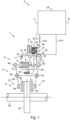
- FIG. 1 schematically represents a railway braking system 1 for a railway vehicle with lining brakes.
- the railway braking system 1 comprises a body 2 here forming a cylinder for both the service brake 6 and the parking brake 7, a control and command unit 3 configured to manage the operation of the service brake 6 and the parking brake 7, a pneumatic pipe routing network connected to the body 2 and to the control and command unit 3, and a braking linkage 4 mechanically connected to the body 2.
- Body 2 here has the shape of a generally closed envelope.
- the service brake 6 comprises a service brake piston 8 movable relative to the body 2 in a first axial direction, a push rod 9 also movable relative to the body 2 in a second axial direction perpendicular to the first axial direction.
- the brake piston 8 delimits with the body 2 a service brake pressure chamber 13.
- the brake piston 8 has two sides, respectively a first side 17 configured to act on the brake linkage 4 via the push rod 9, and a second side 18 opposite the first side 17 and facing the service brake pressure chamber 13.
- the service brake 6 further comprises a notched rod 21 fixed to the second side 18 of the braking piston 8. This notched rod 21 extends longitudinally in the first axial direction.
- the brake piston 8 is configured to move in the body 2 while maintaining the service brake pressure chamber 13 relatively sealed by means of a membrane 14, for example formed by a seal, arranged between this brake piston 8 and the inner edges of the body 2.
- the service brake 6 may comprise a corner piece 10 fixed on the first side 17 of the braking piston 8.
- This corner piece 10 may have a triangular section and be configured to cooperate with a set of rolling stops 11, one of the rolling stops of which may be connected to the body 2 while the other of the rolling stops may be connected to the push rod 9.
- This push rod 9 may be provided with a wear adjuster configured to compensate for the wear of the brake linings in order to prevent excessive play (resulting from wear of the linings) from reducing the braking force.
- the service brake 6 may comprise a spring 12 arranged around the push rod 9, between the bearing stop which is connected to the latter and an inner edge of the body 2. This spring 12 is configured to return the stop which is connected to the push rod 9 against the corner piece 10.
- the service brake 6 may comprise a first orifice 15 formed in the body 2 and configured to allow the movement of the push rod 9 through this first orifice 15.
- the service brake 6 may include a second orifice 16 formed in the body 2 and opening into the service brake pressure chamber 13.
- the service brake pressure chamber 13 is here connected by a first supply line, denoted CA1 on the figure 1 , of the pneumatic pipe routing network, more generally called a brake pipe, which pipe is connected at this second orifice 16 to a source of supply of pneumatic pressure agents (not visible).
- the body 2 comprises a cavity 27 attached to the service brake pressure chamber 13 and in which the parking brake 7 is arranged.
- the parking brake 7 comprises a locking device formed by a locking finger 20 movable relative to the body 2 and extending in the second axial direction.
- the parking brake 7 comprises a holding piston 23 movable relative to the body 2 and delimits with the latter a parking brake pressure chamber 25.
- This holding piston 23 has two sides, respectively a first side 31 on which the locking finger 20 is attached and which faces the parking brake pressure chamber 25, as well as a second side 32 opposite the first side.
- the parking brake 7 comprises a spring element 24 arranged between the body 2 and the second side 32 of the holding piston 23. This spring element 24 is configured to act on this holding piston 23 and consequently on the locking finger 20.
- the holding piston 23 and the spring element 24 can form a movable control device for the parking brake 7.
- the holding piston 23 is configured to move in the body 2 while maintaining the parking brake pressure chamber 25 relatively sealed by means of a membrane disposed between this holding piston 23 and inner edges of the body 2.
- the parking brake 7 comprises a third orifice (not shown) formed in the body 2 and opening into both the parking brake pressure chamber 25 and the service brake pressure chamber 13, which third orifice is configured to allow the locking finger 20 to move through this third orifice.
- the parking brake 7 has a fourth orifice 28 formed in the body 2 and opening into the parking brake pressure chamber 25.
- the unlocking part 29 is accessible for manipulation from outside the body 2 if necessary.
- the unlocking part 29 can be connected to an indicator device provided to indicate a state of the parking brake 7 and/or a state of the service brake 6.
- the unlocking part 29 can be coupled to a switch mechanically secured to this part 29 and having a first position and a second position selected as a function of the position of the unlocking part 29.
- the service brake 6 is arranged in the body 2 and is configured to act on one or more braking members 35 of the railway vehicle via the braking linkage 4.
- the braking member 35 of the vehicle may comprise a brake disc (here seen from above) mounted for example on an axle 36 of the railway vehicle, or directly on the wheel to be braked.
- the brake linkage 4 is provided with a lining device 5 designed to apply forces to the brake disc 35 when the linkage 4 is actuated.
- This device 5 here comprises two lining supports 37 on each of which linings 38 are mechanically secured.
- two gaskets 38 can be mounted on each gasket support 37.
- Each lining 38 is intended to be applied in contact with the disc 35 to reduce its rotation speed and consequently that of the wheel to be braked.
- the braking linkage 4 here comprises levers 40, for example substantially deformable.
- each lever 40 is provided with an upper portion and a lower portion which are integral and which extend from the service and parking brake to the device 5.
- Each portion of the levers 40 can be articulated on a central connector 41 by means of two pivots 42.
- each lever 40 can be connected by a first end to a respective articulation 44, 45.
- the braking linkage 4 can receive the body 2 between the upper portions of the deformable levers 40, at the level of the articulations 44 and 45.
- the body 2 can be rotatably mounted on the articulation 44 which is integral with one end of the push rod 9 while it can be fixedly mounted on the articulation 45, which is directly integral with this body 2.
- each lever 40 can be connected, at a second end opposite its first end, to one of the lining supports 37 at an attachment zone 39 provided on the latter and which is opposite the linings 37.
- the braking linkage 4 may comprise a first fixing member 43 secured to the central connector 41 for mounting this braking linkage 4 on the railway vehicle; so that the lining supports 37 are located on either side of the brake disc 35 (or the wheel of the railway vehicle).
- the bringing together of the articulations 44 and 45 can make it possible to move the lining supports 37 apart from each other and that, conversely, the moving apart of these articulations 44 and 45 can make it possible to tighten the lining supports 37 on the brake disc 35 (or on the wheel of the railway vehicle).
- the control and operating unit 3 is connected to the service brake pressure chamber 13 via the first supply line to which it is connected.
- This unit 3 is connected to the parking brake pressure chamber 25 via the second supply line, marked CA on the figure 1 , to which it is connected.
- This unit 3 is supplied with pneumatic agents by a main pipe, marked CP, which generally runs along the railway vehicle.
- Unit 3 includes systemic elements (not shown in the figure 1 ) which are configured to receive and process representative information relating for example to operating instructions of the railway vehicle, by a first channel of the electric and/or pneumatic and/or manual type, noted A on the figure 1 .
- systemic elements are further configured to receive and process representative information relating to parameters of use of the railway vehicle, by a second channel of the electric and/or pneumatic and/or manual type, denoted B on the figure 1 .
- systemic elements may for example be formed by pneumatic relays and/or solenoid valves and/or pressure switches and/or sensors and/or pressure reducers and/or electrical relays and/or electronic cards and/or central processing units or microprocessors, and/or RAM components comprising registers adapted to record variables of the parameters created and modified during the execution of programs, and/or communication interfaces configured to transmit and receive data, and/or internal storage elements, such as hard disks, which may in particular comprise the executable code of programs allowing the management of the service and parking brakes 6 and 7.
- the control and command unit 3 can be associated with one or more braking linkages of the railway vehicle.
- FIG 2 shows very schematically the railway vehicle 48 provided with an axle forming a support 49 to which the system 1 is mechanically attached, for example by means of a second fixing member 47 which connects the body 2 to the support 49.
- the system 1 comprises at least one force transmission rod 50 mechanically secured by a first end to the support 49 of the vehicle 48 and by a second end opposite the first end to the lining support 37.
- the lining support 37 is here opposite one face of the disc 35 mounted on its axle shaft 36 of the vehicle 48.
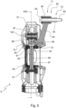
- FIG. 3 illustrates an example of the embodiment of the force transmission rod 50.
- the force transmission rod 50 here has a substantially L- or S-shaped shape.
- the force transmission rod 50 extends substantially in the same plane as that in which said lever 40 extends.
- Such an arrangement is particularly compact and allows maximum movement of the lining support 37 relative to the support 49, thanks to the L-shaped or S-shaped force transmission rod 50 which does not hinder the movement of the lining support 37.
- the connecting rod 50 comprises a main arm 83 extending between a first end 71 where the connecting rod 50 is mechanically secured to the support 49 by a pivot connection 70, and a second end 72, opposite its first end 71, where the connecting rod 50 is mechanically secured, via an axis 84, to the lining support 37 by a pivot connection 75.
- the lining support 37 is provided with a fastening tab 80 to which the connecting rod 50 is mechanically secured.
- the force transmission rod 50 is here mechanically secured to the lining support 37 in the immediate vicinity of the attachment zone 39 of the lever 40.
- the attachment lug 80 is located here in the immediate vicinity of the attachment zone 39 of the lever 40 so that the connecting rod 50 is mechanically secured to the lining support 37 in the immediate vicinity of this attachment zone 39 of the lever 40.
- the trim support 37 comprises a lower base 90 arranged at a distance from the attachment lug 80.
- the attachment zone 39 of the lever extends here between the attachment tab 80 and the lower base.
- the trim support 37 further comprises a mounting axis 89 mounted to move in rotation between the attachment lug 80 and the lower base 90.
- the lining support 37 comprises eyelets 96 formed here immediately below the lower base 90 and into which a stop member 91 is introduced, here formed for example by a pin and circlip assembly.
- the mounting pin 89 passes through the lower base 90 and rests on the stop member 91.
- the mounting pin 89 allows the mechanical securing of the linkage lever (not visible).
- Mounting rings 97 are provided to allow rotation of the mounting axis 89. These mounting rings 97 are housed in the lower base 90 and in a housing 82 of the attachment tab 80.
- the attachment tab 80 is further provided with a mounting member 81, also called an intermediate connecting piece, housed in its housing 82.
- the mounting member 81 is inserted into the housing 82 of the attachment tab 80 and here rests on one end of the mounting shaft 89.
- the mounting axis 89 is here interposed between the mounting member 81 and the stop member 91 located at the level of the lower base 90.
- the mounting member could be remote from the mounting axis.
- the mounting member 81 is here formed of a substantially cylindrical body 99 extending longitudinally and having an orifice passing 98 through the cylindrical body 99 in a transverse direction.
- the cylindrical body 99 is here further provided with an upper opening 100 and a stopper 101 movable in translation in the cylindrical body 99.
- the mounting member 81 here has dimensions such that it does not move in the attachment tab 80.
- the mounting member 81 is mounted in the housing 82 of the attachment tab 80 without substantial play.
- the lining support 37 here comprises a locking piece 87 fixedly mounted in the housing 82 of the attachment tab 80.
- the locking piece 87 is superimposed with the mounting member 81, so that the latter is here located between the mounting axis 89 and the locking piece 87.
- the locking part 87 is provided with an orifice crossed by a fixing member 102, for example a pin and circlip assembly, which fixing member 102 is mounted in engagement on the attachment tab 80.
- the lining support 37 further comprises here an elastic member 88 interposed between the locking part 87 and the mounting member 81.
- the elastic member bears against the movable stopper 101 in the cylindrical body 99 of the mounting member 81.
- the elastic member 88 can be formed by one or more Belleville washers.
- the axis 84 of the connecting rod 50 is integral with the arm 83 and is formed as a projection therefrom, at the level of the second end 72 of the connecting rod 50.
- the axis 84 of the connecting rod 50 is introduced into the through hole 98 in the cylindrical body 99 of the mounting member 81.
- the pivot connection 75 is thus formed and the connecting rod 50 is rotatably mounted by its second end 72 in the mounting member 81.
- the elastic member 88 can make it possible to exert a force via the plug 101 on the axis 84 of the connecting rod 50. In particular, this can generate a resistive torque to limit the rotation of the connecting rod 50 relative to the lining support 37 during rolling phases without application of the brake.
- the elastic member 88 does not hinder the rotation of the connecting rod 50 relative to the lining support 37 in order to best apply the braking force to the braking member of the vehicle.
- the arrangement of the elastic member 88 makes it possible to provide a slight suspension of the device 5 comprising the lining support 37 and the linings 38 relative to the connecting rod 50.
- the arrangement of the lining support 37, the connecting rod 50, the lever and the support (not visible) is such that the connecting rod 50 cannot disengage from the lining support, under normal conditions of use.
- the latter is provided with a tubular portion 92 in which a fixing sleeve 93 is mounted.
- a ring for example made of composite, can be mounted on the fixing sleeve 93, to avoid friction between this sleeve 93 and the tubular portion 92.
- This ring can also provide a slight suspension between the connecting rod and the support to which it is mechanically attached.
- a fixing member 94 for example a screw, passes through the fixing sleeve 93 and is fixed to the support (not visible) of the vehicle.
- a washer 95 is interposed between a head of the fixing member 94 and the tubular portion 92.
- the tubular portion 92 of the connecting rod 50 is movable in rotation relative to the fixing sleeve 93, around the pivot connection 70 thus formed.
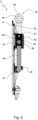
- THE figures 8 to 10 illustrate another example of embodiment of the force transmission rod 50, which differs from the rod described with reference to Figures 4 to 10 only in that it lacks an axis coming from the same material as the main arm. Its description will therefore be made more briefly than above.
- the mounting member 81 is here formed of a substantially cylindrical body 99 extending longitudinally and having an orifice passing 98 through the cylindrical body 99 in a transverse direction.
- the cylindrical body here lacks an upper opening and a stopper which can move in translation in the cylindrical body.
- the mounting member 81 is mounted in the housing 82 of the attachment tab 80 without substantial play.
- the mounting shaft 89 is mounted to be rotatable between the attachment lug 80, where it is in the immediate vicinity of the mounting member 81, and the lower base 90, where it rests on the stop member 91.
- the locking piece 87 is fixedly mounted in the housing 82 of the attachment tab 80, and is superimposed with the mounting member 81, so that the latter is here located between the mounting axis 89 and the locking piece 87.
- the locking part 87 is provided with an orifice crossed by a fixing member 102, for example a pin and circlip assembly, which fixing member 102 is mounted in engagement on the attachment tab 80.
- the connecting rod 50 is provided, at its second end 72, with a sleeve 85 fitted into its main arm 83, and with a fixing member 86, formed for example here by a screw, mounted through the sleeve 85 and mechanically secured in the main arm 83.
- the assembly formed by the sleeve 85 and the fixing member 86 is introduced into the through-hole 98 in the cylindrical body 99 of the mounting member 81.
- the pivot connection 75 is thus formed and the connecting rod 50 is rotatably mounted by its second end 72 in the mounting member 81.
- the fixing sleeve 93 is mounted in the tubular portion 92, the fixing member 94 passes through the fixing sleeve 93 and is fixed to the support (not visible) of the vehicle, with the washer 95 which is interposed between a head of the fixing member 94 and the tubular portion 92.
- the tubular portion 92 of the connecting rod 50 is movable in rotation relative to the fixing sleeve 93, around the pivot connection 70 thus formed.
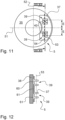
- the device 5 is opposite the brake disc 35.
- the device 5 whose lining support 37 and linings 38, have a general longitudinal orientation and a general transverse orientation.
- a longitudinal central axis 52 and a transverse central axis 51 are illustrated.
- the transverse central axis 51 also corresponds, in the position illustrated in the figure 11 , to a transverse central axis of the device 5.
- the lever 40 is mechanically secured to the lining support 37 via the attachment zones 39.
- the attachment zones 39 are located at most approximately 35 mm from the transverse central axis 51 of the device 5. This means that the distances E shown on the figure 3 are each at most equal to 35 mm.
- the attachment zones 39 are located on either side of the transverse central axis 51 and therefore extend at most, according to the general longitudinal orientation, over approximately 70 mm.
- the attachment zone(s) 39 may be located between approximately 0 and approximately 35 mm from the transverse central axis 51 and they may extend in a general longitudinal orientation and over a length of between approximately 15 mm and approximately 70 mm.
- the attachment zones 39 extend on either side of the transverse central axis 51 in an interrupted manner.
- attachment zones 39 are distinct.
- the attachment zones may extend on either side of the transverse central axis 51 in an uninterrupted manner.
- a longitudinal axis of application of the forces 53 is illustrated in fine dotted lines, while a longitudinal axis of maintenance 54 is illustrated in thick dotted lines.
- the longitudinal axis of application of the forces 53 is that passing through the attachment zones 39 of the lining support 37, which allow the mechanical securing of the levers 40, while the longitudinal holding axis 54 is slightly offset relative to the longitudinal axis of application of the forces 53 and corresponds to the zone of attachment of the linings 38 on the lining support 37.
- the device 5 comprises at least two support zones 60 on the brake disc 35 and at least one withdrawal zone 61 located between the two support zones 60.
- the device may comprise a plurality of support zones between which withdrawal zones are formed.
- the support zones 60 and withdrawal zones 61 follow one another according to the general longitudinal orientation of the device 5.
- the two support zones 60 and the withdrawal zone 61 are here provided on one face of the lining support 37, opposite that on which the attachment zones 39 are formed.
- Each of the two support zones 60 is here arranged so as to be opposite a respective lining 38.
- the support areas may be formed by protrusions on the lining supports and/or that the withdrawal areas may be formed by recesses in the lining supports.
- the support areas and the withdrawal areas are thus in offset planes.
- the support zones 60 and the withdrawal zone 61 extend entirely along the general transverse orientation of the device 5.
- support zones 60 and the withdrawal zone 61 are here arranged substantially symmetrically with respect to the transverse central axis 51.
- the device 5 of the braking linkage 4 which comes into contact with the brake disc 35 is therefore provided with a so-called discontinuous support surface, with only the support zones 60 which make it possible to transmit forces onto the brake disc 35. This makes it possible to distribute the transmission of forces onto the brake disc 35.
- the support zones 60 are closer to each other and to the transverse central axis 51, and the withdrawal zone 61 is more restricted.
- the attachment areas 39 are identical to those described above.
- the lever 40 is mechanically secured to the lining support 37 via a single attachment zone 39.
- the attachment zone 39 is located at the level of the transverse central axis 51 of the device 5 and extends slightly on either side of this axis 51.
- the attachment area extends only from about 10 mm to about 20 mm on either side of the transverse central axis 51.
- the distance E represented on the figure 10 is at most equal to approximately 40 mm, depending on the general longitudinal orientation.
- such a single attachment zone may extend in the general longitudinal orientation and over a length of between about 15 mm and about 70 mm.
- the single attachment zone 39 here extends on either side of the transverse central axis 51 in an uninterrupted manner.
- the device 5 comprises at least two support zones 60 on the brake disc 35 and at least one withdrawal zone 61 located between the two support zones 60.
- the support zones 60 and withdrawal zones 61 follow one another according to the general longitudinal orientation of the device 5 and are identical to that of the device illustrated in the Figures 11 to 14 .
- the two support zones 60 and the withdrawal zone 61 are here provided on a face of the lining support 37, opposite that on which the attachment zones 39 are formed, and each of the two support zones 60 is here provided so as to be opposite a respective lining 38.
- Preferred contact zones 65 are thus provided on the linings 38, which correspond respectively to the support zones 60.
- the support zones 60 and the withdrawal zone 61 extend entirely along the general transverse orientation of the device 5, and are here arranged substantially symmetrically with respect to the transverse central axis 51.
- the device 5 of the braking linkage 4 which comes into contact with the brake disc 35 is therefore provided with a so-called discontinuous support surface, with only the support zones 60 which make it possible to transmit forces onto the brake disc 35. This makes it possible to distribute the transmission of forces onto the brake disc 35.
- the device 5 is devoid of a withdrawal zone and therefore only has a single support zone 60 which extends over the entire face of the lining support 37.
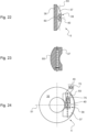
- FIG 24 is a view similar to that of the figure 18 , with in addition the force transmission rod 50, visible here very schematically in relation to the Figures 3 to 10 .
- the force transmission rod 50 is mechanically secured at its first end 71 to the support 49 of the vehicle and at its second end 72 opposite its first end to the lining support 37, and in the immediate vicinity of the single attachment zone 39 of the lever 40 on this same lining support 37.
- the force transmission rod 50 is mechanically secured by the pivot connections 70, 75 respectively to the support 49 of the vehicle and to the lining support 37.
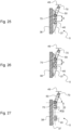
- FIG 25 also shows very schematically the force transmission rod 50 secured to the lining support 37 of a device 5 similar to that described with reference to the figure 22 , without a withdrawal zone on the lining support 37, and with a single attachment zone 39 of the lever 40 on the lining support 37.
- FIG 26 also shows very schematically the force transmission rod 50 secured to the lining support 37 of a device 5 similar to that described with reference to the figure 19 , with support zones 60 and a withdrawal zone 61 provided on the lining support 37, and with a single attachment zone 39 of the lever 40 on the lining support 37.
- FIG 27 also shows very schematically the force transmission rod 50 secured to the lining support 37 of a device 5 fairly close to those described with reference to figures 12 And 15 , but without a withdrawal zone on the lining support 37 (in the manner of those described with reference to figures 22 And 25 ), while it comprises attachment zones 39 distinct from the lever 40 on the lining support 37.
- FIG 28 shows very schematically the force transmission rod 50 secured to the lining support 37 of a device 5 fairly close to those described above, but whose support zone 60 is here formed in a staircase.
- the zone support 60 comprises different support portions 63 and 64 more or less offset relative to the adjacent withdrawal zone 61.
- the support portion 63 forms a so-called over-support zone.
- the trim support may include one or more recessed areas extending from about 100 mm to about 300 mm from the transverse central axis of said device.
- the withdrawal zone(s) may be formed by cavities having a depth of, for example, between approximately 0.1 mm and approximately 0.5 mm.
- the lining support may comprise a single withdrawal zone extending over approximately 180 mm (or over 90 mm on either side of the transverse axis), and having a cavity of approximately 0.2 mm; the remainder of the lining support generally forming one or more support zones.
- the lining support may comprise a first withdrawal zone extending over approximately 120 mm (or over 60 mm on either side of the transverse axis), and having a cavity of approximately 0.3 mm, then second withdrawal zones immediately or not following the first withdrawal zone, each extending over approximately 60 mm and having a cavity of approximately 0.15 mm; the remainder of the lining support generally forming one or more support zones.
- the lining support may comprise a first withdrawal zone extending over approximately 120 mm (or over 60 mm on either side of the transverse axis), and having a cavity of approximately 0.35 mm, then second withdrawal zones immediately or not following the first withdrawal zone, each extending over approximately 60 mm and having a cavity of approximately 0.2 mm; the remainder of the lining support generally forming one or more support zones.
- the force transmission rod may have a Y shape, or an H shape, or even an I shape, rather than an L or S shape.
- the elastic member may be formed by at least one spring, for example helical, or at least one elastomer rather than by one or more Belleville washers.
- the support areas and/or the withdrawal areas may be provided in the linings rather than in the lining supports.
- Some areas of support and/or withdrawal may extend completely along the general transverse orientation, while other such areas may extend only partially.
- the support and withdrawal zones are not arranged substantially symmetrically with respect to the transverse central axis.
- the attachment area of the trim support to which the lever is attached is located more than 35 mm from the transverse central axis of the device.
- the railway braking system may differ from that described above in that it may be a service brake only, or a parking brake, and the mechanism may be spring-loaded as described for example in the document EP 2 154 040 .
Landscapes
- Engineering & Computer Science (AREA)
- General Engineering & Computer Science (AREA)
- Mechanical Engineering (AREA)
- Braking Arrangements (AREA)
Claims (15)
- Eisenbahnbremssystem für ein Eisenbahnfahrzeug, umfassend ein Bremsgestänge (4), eine Betriebs- und/oder eine Feststellbremse (6, 7), die dazu konfiguriert sind, auf mindestens ein Bremselement (35) des Eisenbahnfahrzeugs mit Hilfe des Bremsgestänges einzuwirken, welches mit mindestens einer Vorrichtung (5) versehen ist, die mindestens einen Bremsbelagträger (37) und mindestens einen Bremsbelag (38) aufweist, der mechanisch an dem mindestens einen Bremsbelagträger befestigt ist, und mindestens eine Kraftübertragungsverbindungsstange (50), die mit einem ersten Ende (71) an einem Träger (49) des Fahrzeugs und mit einem gegenüberliegenden zweiten Ende (72) an mindestens einem Bremsbelagträger mechanisch befestigt ist, dadurch gekennzeichnet, dass der mindestens eine Bremsbelagträger ein Befestigungssystem (80) umfasst, das mit einem Gehäuse (82) und einem Montageelement (81), das im Gehäuse (82) untergebracht ist, versehen ist, und wobei die mindestens eine Kraftübertragungsverbindungsstange mit ihrem zweiten Ende im Montageelement drehbar gelagert ist.
- Eisenbahnbremssystem nach Anspruch 1, dadurch gekennzeichnet, dass, gekennzeichnet dadurch, dass die mindestens eine Kraftübertragungsverbindungsstange (50) eine im Wesentlichen L-förmige oder S-förmige oder H-förmig oder Y-förmige Form aufweist.
- Eisenbahnbremssystem nach einem der Ansprüche 1 und 2, dadurch gekennzeichnet, dass die mindestens eine Kraftübertragungsverbindungsstange (50) durch Drehverbindungen (70, 75) jeweils mechanisch am Träger des Fahrzeugs und dem mindestens einen Bremsbelagträger befestigt ist.
- Eisenbahnbremssystem nach einem der Ansprüche 1 bis 3, dadurch gekennzeichnet, dass die mindestens eine Kraftübertragungsverbindungsstange (50) ihrem zweiten Ende (72) mit einer Welle (84) versehen ist, die einstückig mit der Kraftübertragungsverbindungsstange ausgebildet ist und von einem Hauptarm (83) der Übertragungsverbindungsstange vorsteht.
- Eisenbahnbremssystem nach einem der Ansprüche 1 bis 3, dadurch gekennzeichnet, dass die mindestens eine Kraftübertragungsverbindungsstange (50) an ihrem zweiten Ende (72) mit einer Hülse (85), die in einen Hauptarm (83) der Übertragungsverbindungsstange eingesetzt ist, und mit einem Fixierungselement (86) versehen ist, das durch die Hülse gelagert und im Hauptarm (83) mechanisch befestigt ist.
- Eisenbahnbremssystem nach einem der Ansprüche 1 bis 5, dadurch gekennzeichnet, dass der mindestens eine Bremsbelagträger (37) ein Blockierbauteil (87) umfasst, das fest im Gehäuse (82) gelagert ist und mit dem Montageelement (81) überlagert wird.
- Eisenbahnbremssystem nach Anspruch 6, dadurch gekennzeichnet, dass der mindestens eine Bremsbelagträger (37) ferner mindestens ein elastisches Element (88) umfasst, das zwischen dem Blockierbauteil (87) und dem Montageelement (81) eingefügt ist.
- Eisenbahnbremssystem nach Anspruch 7, dadurch gekennzeichnet, dass das mindestens eine elastische Element (88) aus mindestens einer oder mehreren Tellerfedern oder mindestens einer Feder, zum Beispiel einer Schraubenfeder, oder mindestens einem Elastomer ausgebildet ist.
- Eisenbahnbremssystem nach einem der Ansprüche 1 bis 8, dadurch gekennzeichnet, dass das Gestänge mindestens einen Hebel (40) umfasst, der sich von der Betriebs- und/oder Feststellbremse (6, 7) bis zu der Vorrichtung (5) erstreckt, an der er an einem Befestigungsbereich (39) des mindestens einen Bremsbelagsträgers (37) fixiert ist, wobei der mindestens eine Hebel dazu konfiguriert ist, eine Betätigungskraft der Betriebs- und/oder Feststellbremse auf die Vorrichtung zu übertragen, und die mindestens eine Kraftübertragungsverbindungsstange (50) in der unmittelbaren Nähe des Befestigungsbereichs des mindestens einen Hebel fixiert ist.
- Eisenbahnbremssystem nach Anspruch 9, dadurch gekennzeichnet, dass der mindestens eine Bremsbelagträger (37) mit einer unteren Basis (90) und einer Lagerwelle (89), die drehbar zwischen dem Befestigungssystem (80) und der unteren Basis gelagert ist, versehen ist, wobei der Hebel (40) mechanisch an der Lagerwelle befestigt ist.
- Eisenbahnbremssystem nach Anspruch 10, dadurch gekennzeichnet, dass die Lagerwelle (89) zwischen dem Montageelement (81) und einem Anschlagelement (91), das sich an der unteren Basis (90) befindet, eingefügt ist.
- Eisenbahnbremssystem nach einem der Ansprüche 9 bis 11, dadurch gekennzeichnet, dass der Befestigungsbereich (39) höchstens 35 mm von einer Quermittelachse (51) der Vorrichtung (5) befindet und den mindestens einen Bremsbelagträger (37) und den mindestens einen Bremsbelag (38) aufweist.
- Eisenbahnbremssystem nach einem der Ansprüche 9 bis 12, dadurch gekennzeichnet, dass sich der mindestens eine Kraftübertragungsverbindungsstange (50) im Wesentlichen in derselben Ebene erstreckt wie die Ebene, in der sich der mindestens eine Hebel (40) erstreckt.
- System nach einem der Ansprüche 1 bis 13, dadurch gekennzeichnet, dass die Vorrichtung (5) mindestens zwei Auflagebereiche (60) für das mindestens eine Bremselement (35) und mindestens einen Rückzugsbereich (61) umfasst, der sich zwischen den beiden Auflagebereichen befindet, und mindestens ein Auflagebereich abgestuft ausgebildet ist und unterschiedliche Auflageabschnitte (63, 64) umfasst, die in Bezug auf den Rückzugsbereich mehr oder weniger versetzt sind.
- Eisenbahnfahrzeug, das mindestens ein Bremselement (35), insbesondere eine Bremsscheibe, und mindestens ein Eisenbahnbremssystem (1) nach einem der Ansprüche 1 bis 14 umfasst, das dazu konfiguriert ist, auf das mindestens eine Bremselement einzuwirken.
Applications Claiming Priority (4)
| Application Number | Priority Date | Filing Date | Title |
|---|---|---|---|
| FR1908510A FR3099118B1 (fr) | 2019-07-26 | 2019-07-26 | Système de freinage ferroviaire comportant une timonerie de freinage et véhicule ferroviaire pourvu d’un tel système |
| FR1908512A FR3099119B1 (fr) | 2019-07-26 | 2019-07-26 | Système de freinage ferroviaire comportant une timonerie de freinage et véhicule ferroviaire pourvu d’un tel système |
| FR1911666A FR3102129B1 (fr) | 2019-10-18 | 2019-10-18 | Système de freinage ferroviaire comportant une timonerie de freinage et véhicule ferroviaire pourvu d’un tel système |
| PCT/EP2020/070887 WO2021018743A1 (fr) | 2019-07-26 | 2020-07-23 | Systeme de freinage ferroviaire comportant une timonerie de freinage et vehicule ferroviaire pourvu d'un tel systeme |
Publications (2)
| Publication Number | Publication Date |
|---|---|
| EP4003810A1 EP4003810A1 (de) | 2022-06-01 |
| EP4003810B1 true EP4003810B1 (de) | 2025-02-19 |
Family
ID=71738161
Family Applications (3)
| Application Number | Title | Priority Date | Filing Date |
|---|---|---|---|
| EP20743698.1A Active EP4004396B1 (de) | 2019-07-26 | 2020-07-23 | Schienenbremssystem mit bremsgestänge und schienenfahrzeug mit einem solchen system |
| EP20743699.9A Active EP4003809B1 (de) | 2019-07-26 | 2020-07-23 | Schienenbremssystem mit bremsgestänge und schienenfahrzeug mit einem solchen system |
| EP20757224.9A Active EP4003810B1 (de) | 2019-07-26 | 2020-07-23 | Schienenbremssystem mit bremsgestänge und schienenfahrzeug mit einem solchen system |
Family Applications Before (2)
| Application Number | Title | Priority Date | Filing Date |
|---|---|---|---|
| EP20743698.1A Active EP4004396B1 (de) | 2019-07-26 | 2020-07-23 | Schienenbremssystem mit bremsgestänge und schienenfahrzeug mit einem solchen system |
| EP20743699.9A Active EP4003809B1 (de) | 2019-07-26 | 2020-07-23 | Schienenbremssystem mit bremsgestänge und schienenfahrzeug mit einem solchen system |
Country Status (7)
| Country | Link |
|---|---|
| US (3) | US12344289B2 (de) |
| EP (3) | EP4004396B1 (de) |
| CN (3) | CN114174691B (de) |
| AU (3) | AU2020321464B2 (de) |
| CA (3) | CA3144692A1 (de) |
| ES (3) | ES3028782T3 (de) |
| WO (3) | WO2021018744A1 (de) |
Families Citing this family (1)
| Publication number | Priority date | Publication date | Assignee | Title |
|---|---|---|---|---|
| US12344289B2 (en) * | 2019-07-26 | 2025-07-01 | Wabtec Hauts-De-France | Braking system comprising brake rigging, and vehicle equipped with such a braking system |
Family Cites Families (42)
| Publication number | Priority date | Publication date | Assignee | Title |
|---|---|---|---|---|
| FR816306A (fr) * | 1937-01-13 | 1937-08-05 | Administration Des Chemins De | Dispositif pour le freinage des véhicules |
| US2236311A (en) * | 1938-03-29 | 1941-03-25 | Budd Wheel Co | Brake shoe |
| US3422933A (en) * | 1967-08-17 | 1969-01-21 | Gen Motors Corp | Self-energized disc brake assembly |
| US3530493A (en) * | 1968-10-02 | 1970-09-22 | Kelsey Hayes Co | Floating friction brake for rotary disk |
| DE2233180C3 (de) * | 1972-07-06 | 1979-08-09 | Mak Maschinenbau Gmbh, 2300 Kiel | Scheibenbremse für seitenverschiebliche Radsätze von Schienenfahrzeugen |
| DE2547530A1 (de) * | 1975-10-23 | 1977-04-28 | Knorr Bremse Gmbh | Bremsbacke fuer scheibenbremsen |
| FR2365726A1 (fr) * | 1976-09-27 | 1978-04-21 | Pont A Mousson | Dispositif de maintien d'une garniture de friction sur un support dans un frein a disque, notamment pour vehicules ferroviaires |
| US4181199A (en) * | 1978-05-11 | 1980-01-01 | Dana Corporation | Caliper type disc brake |
| US4572336A (en) * | 1983-06-20 | 1986-02-25 | Allied Corporation | Disc brake and anti-rotational heat shield therefor |
| FR2631600B1 (fr) * | 1988-05-18 | 1990-07-13 | Alsthom Creusot Rail | Dispositif de freinage d'un essieu relie elastiquement a un chassis |
| FR2678334B1 (fr) * | 1991-06-28 | 1997-04-30 | Carbone Ind | Dispositif de plaquette de frein a disque en particulier a garniture en carbone-carbone. |
| JPH0616968U (ja) * | 1992-08-05 | 1994-03-04 | 新明和工業株式会社 | 運転シミュレータ装置 |
| FR2706844A1 (en) * | 1993-06-23 | 1994-12-30 | Gec Alsthom Transport Sa | Braking device for a bogie |
| CA2109377C (en) * | 1993-07-23 | 1998-08-04 | Joseph C. Kahr | Disc brake shoe assembly |
| DE4325066C2 (de) * | 1993-07-26 | 1996-05-15 | Eagle Picher Ind Gmbh | Bremsbacke |
| US5433301A (en) * | 1993-12-13 | 1995-07-18 | Rockwell International Corporation | Disc brake assembly including a configured load plate |
| FR2729357A1 (fr) * | 1994-12-22 | 1996-07-19 | Soc D Forges De Fresnes | Dispositif de freinage pour vehicule ferroviaire |
| US5601163A (en) * | 1996-03-05 | 1997-02-11 | Iri International Corporation | Automatic adjuster for brake calipers |
| US6206151B1 (en) * | 1999-04-17 | 2001-03-27 | Shimano, Inc. | Ventilated pad for a bicycle disc brake |
| US7032723B2 (en) * | 2002-10-22 | 2006-04-25 | Ford Global Technologies, Llc | Brake assembly with tuned mass damper |
| FR2853378B1 (fr) * | 2003-04-02 | 2006-03-10 | Carbone Lorraine Composants | Plaquettes de frein a disque ventilees |
| US7314122B2 (en) * | 2003-08-04 | 2008-01-01 | Everett Richard C | Bicycle brake assembly having multiple replaceable brake pads |
| ES2320154T3 (es) * | 2004-07-01 | 2009-05-19 | Knorr-Bremse Systeme Fur Schienenfahrzeuge Gmbh | Pastilla de freno para un freno de disco de un vehiculo sobre railes. |
| DE102004049657B4 (de) * | 2004-10-11 | 2007-09-20 | Knorr-Bremse Systeme für Nutzfahrzeuge GmbH | Bremsbelag |
| US20070119665A1 (en) * | 2005-11-28 | 2007-05-31 | Manuel Barbosa | Outer pad abutment design for frame type calipers |
| FR2924478B1 (fr) * | 2007-11-29 | 2009-12-04 | Afe Metal | Dispositif de freinage pour materiel roulant ferroviaire. |
| US20090145702A1 (en) * | 2007-12-06 | 2009-06-11 | Kelsey-Hayes Company | Brake pad for a vehicle disc brake assembly |
| DE102008039672B4 (de) * | 2008-07-24 | 2013-09-19 | Becorit Gmbh | Bremsbelag für eine Scheibenbremse und Bremsbelagsystem |
| FR2934981B1 (fr) | 2008-08-13 | 2010-09-24 | Faiveley Transp Amiens | Actionneur de frein de parking ou de secours pour frein a deverrouillage a billes |
| AT507509A3 (de) * | 2008-10-22 | 2012-02-15 | Siemens Ag Oesterreich | Scheibenbremse für ein schienenfahrzeug mit einem elektrisch isolierten bremsbelaghalter |
| DE112009004577B4 (de) * | 2009-03-24 | 2014-04-03 | Toyota Jidosha Kabushiki Kaisha | Bremssystem |
| JP5406632B2 (ja) * | 2009-08-25 | 2014-02-05 | カヤバ工業株式会社 | キャリパブレーキ装置 |
| DE202010017749U1 (de) * | 2010-10-29 | 2012-12-03 | Knorr-Bremse Systeme für Nutzfahrzeuge GmbH | Bremsbelag für eine Scheibenbremse |
| DE102011001562B4 (de) * | 2011-03-25 | 2012-12-13 | Dömer GmbH & Co. KG | Reibbelagträgerplatte |
| FR2981903B1 (fr) * | 2011-10-28 | 2013-11-29 | Sncf | Dispositif de freinage pour vehicule ferroviaire |
| DE102012207194A1 (de) * | 2012-04-30 | 2013-10-31 | Siemens Aktiengesellschaft | Bremseinheit für ein Fahrzeug und Fahrzeug mit einer derartigen Bremseinheit |
| DE102013008227A1 (de) * | 2013-05-13 | 2014-11-13 | Knorr-Bremse Systeme für Schienenfahrzeuge GmbH | Verfahren und Vorrichtung zum Bestimmen eines Bremsmoments an einer Bremsanlage für ein Schienenfahrzeug |
| FR3008668B1 (fr) * | 2013-07-17 | 2015-09-04 | Faiveley Transp Amiens | Systeme de freinage ferroviaire et procede de freinage d'un vehicule ferroviaire comportant un tel systeme |
| US9550504B2 (en) * | 2014-12-16 | 2017-01-24 | Faiveley Transport Amiens | Rail vehicle braking system and braking method for a rail vehicle comprising such a system |
| EP3396194A4 (de) * | 2015-12-25 | 2019-01-16 | Nippon Steel & Sumitomo Metal Corporation | Bremsbelag für schienenfahrzeuge und scheibenbremse damit |
| DE102017101028A1 (de) * | 2017-01-19 | 2018-07-19 | Knorr-Bremse Systeme für Schienenfahrzeuge GmbH | Bremszangeneinheit |
| US12344289B2 (en) * | 2019-07-26 | 2025-07-01 | Wabtec Hauts-De-France | Braking system comprising brake rigging, and vehicle equipped with such a braking system |
-
2020
- 2020-07-23 US US17/628,182 patent/US12344289B2/en active Active
- 2020-07-23 EP EP20743698.1A patent/EP4004396B1/de active Active
- 2020-07-23 WO PCT/EP2020/070888 patent/WO2021018744A1/fr not_active Ceased
- 2020-07-23 WO PCT/EP2020/070889 patent/WO2021018745A1/fr not_active Ceased
- 2020-07-23 CA CA3144692A patent/CA3144692A1/fr active Pending
- 2020-07-23 EP EP20743699.9A patent/EP4003809B1/de active Active
- 2020-07-23 AU AU2020321464A patent/AU2020321464B2/en active Active
- 2020-07-23 CN CN202080054362.2A patent/CN114174691B/zh active Active
- 2020-07-23 US US17/628,609 patent/US20220268328A1/en not_active Abandoned
- 2020-07-23 ES ES20757224T patent/ES3028782T3/es active Active
- 2020-07-23 CA CA3144856A patent/CA3144856A1/fr active Pending
- 2020-07-23 US US17/628,548 patent/US20220258777A1/en active Pending
- 2020-07-23 ES ES20743698T patent/ES3047712T3/es active Active
- 2020-07-23 EP EP20757224.9A patent/EP4003810B1/de active Active
- 2020-07-23 CA CA3144689A patent/CA3144689A1/fr active Pending
- 2020-07-23 CN CN202080053896.3A patent/CN114174690B/zh active Active
- 2020-07-23 AU AU2020321465A patent/AU2020321465B2/en active Active
- 2020-07-23 ES ES20743699T patent/ES2987631T3/es active Active
- 2020-07-23 WO PCT/EP2020/070887 patent/WO2021018743A1/fr not_active Ceased
- 2020-07-23 CN CN202080053496.2A patent/CN114207308A/zh active Pending
- 2020-07-23 AU AU2020322310A patent/AU2020322310B2/en active Active
Also Published As
| Publication number | Publication date |
|---|---|
| CN114207308A (zh) | 2022-03-18 |
| US20220268328A1 (en) | 2022-08-25 |
| EP4004396A1 (de) | 2022-06-01 |
| CA3144689A1 (fr) | 2021-02-04 |
| CN114174691B (zh) | 2024-04-09 |
| CN114174690A (zh) | 2022-03-11 |
| WO2021018745A1 (fr) | 2021-02-04 |
| US20220258777A1 (en) | 2022-08-18 |
| EP4004396B1 (de) | 2025-08-27 |
| ES3047712T3 (en) | 2025-12-04 |
| ES3028782T3 (en) | 2025-06-20 |
| AU2020322310B2 (en) | 2026-03-05 |
| AU2020322310A1 (en) | 2022-03-10 |
| EP4003809A1 (de) | 2022-06-01 |
| CA3144692A1 (fr) | 2021-02-04 |
| US20220258776A1 (en) | 2022-08-18 |
| EP4003810A1 (de) | 2022-06-01 |
| AU2020321464A1 (en) | 2022-03-03 |
| WO2021018743A1 (fr) | 2021-02-04 |
| CA3144856A1 (fr) | 2021-02-04 |
| ES2987631T3 (es) | 2024-11-15 |
| AU2020321464B2 (en) | 2026-02-26 |
| CN114174690B (zh) | 2024-01-30 |
| US12344289B2 (en) | 2025-07-01 |
| EP4003809B1 (de) | 2024-04-10 |
| AU2020321465B2 (en) | 2026-02-05 |
| CN114174691A (zh) | 2022-03-11 |
| AU2020321465A1 (en) | 2022-03-10 |
| WO2021018744A1 (fr) | 2021-02-04 |
Similar Documents
| Publication | Publication Date | Title |
|---|---|---|
| FR2934981A1 (fr) | Actionneur de frein de parking ou de secours pour frein a deverrouillage a billes | |
| EP3642091B1 (de) | Bremssystem für schienenfahrzeuge | |
| EP0772749A1 (de) | Bremsbelag und hiermit ausgerüstete scheibenbremse | |
| CA3015704C (fr) | Systeme de freinage ferroviaire pour vehicule ferroviaire | |
| EP0486341B1 (de) | Mechanisch betätigbare Trommelbremse | |
| EP0803031A1 (de) | Scheibenbremse mit mechanischer betätigungsvorrichtung | |
| EP4004396B1 (de) | Schienenbremssystem mit bremsgestänge und schienenfahrzeug mit einem solchen system | |
| FR3102129A1 (fr) | Système de freinage ferroviaire comportant une timonerie de freinage et véhicule ferroviaire pourvu d’un tel système | |
| EP1053409A1 (de) | Scheibenbremse mit ausgeglichener reaktion | |
| FR2716856A1 (fr) | Etrier de frein à mâchoires pour freins à disque de véhicules sur rails . | |
| EP0395460B1 (de) | Schwimmsattel-Scheibenbremse | |
| FR3099118A1 (fr) | Système de freinage ferroviaire comportant une timonerie de freinage et véhicule ferroviaire pourvu d’un tel système | |
| FR3099119A1 (fr) | Système de freinage ferroviaire comportant une timonerie de freinage et véhicule ferroviaire pourvu d’un tel système | |
| FR2722262A1 (fr) | Dispositif de commande d'embrayage | |
| WO2026022432A1 (fr) | Système de freinage ferroviaire pour véhicule ferroviaire à freins à au moins une garniture ou à au moins une semelle | |
| EP1270980B1 (de) | Scheibenbremse, insbesondere für Industriegebrauch | |
| FR3157328A1 (fr) | Système de freinage ferroviaire pour véhicule ferroviaire à freins à au moins une garniture ou à au moins une semelle | |
| FR2580048A1 (de) | ||
| EP0696689A1 (de) | Schwenksattel-Scheibenbremse | |
| EP4522883A1 (de) | Schienenbremssystem für ein schienenfahrzeug, und mit einem solchen system ausgestattetes schienenfahrzeug | |
| EP1936225A1 (de) | Bremsvorrichtung | |
| EP1480863A1 (de) | Befestigungsvorrichtung zwischen einer querstange und einem bremsklotze für ein eisenbahndrehgestell | |
| BE514987A (de) | ||
| EP0044772A2 (de) | Scheibenbremse mit beweglichem Sattel |
Legal Events
| Date | Code | Title | Description |
|---|---|---|---|
| STAA | Information on the status of an ep patent application or granted ep patent |
Free format text: STATUS: UNKNOWN |
|
| STAA | Information on the status of an ep patent application or granted ep patent |
Free format text: STATUS: THE INTERNATIONAL PUBLICATION HAS BEEN MADE |
|
| PUAI | Public reference made under article 153(3) epc to a published international application that has entered the european phase |
Free format text: ORIGINAL CODE: 0009012 |
|
| STAA | Information on the status of an ep patent application or granted ep patent |
Free format text: STATUS: REQUEST FOR EXAMINATION WAS MADE |
|
| 17P | Request for examination filed |
Effective date: 20220225 |
|
| AK | Designated contracting states |
Kind code of ref document: A1 Designated state(s): AL AT BE BG CH CY CZ DE DK EE ES FI FR GB GR HR HU IE IS IT LI LT LU LV MC MK MT NL NO PL PT RO RS SE SI SK SM TR |
|
| DAV | Request for validation of the european patent (deleted) | ||
| DAX | Request for extension of the european patent (deleted) | ||
| P01 | Opt-out of the competence of the unified patent court (upc) registered |
Effective date: 20230530 |
|
| RAP3 | Party data changed (applicant data changed or rights of an application transferred) |
Owner name: WABTEC HAUTS-DE-FRANCE |
|
| GRAP | Despatch of communication of intention to grant a patent |
Free format text: ORIGINAL CODE: EPIDOSNIGR1 |
|
| STAA | Information on the status of an ep patent application or granted ep patent |
Free format text: STATUS: GRANT OF PATENT IS INTENDED |
|
| INTG | Intention to grant announced |
Effective date: 20241004 |
|
| GRAS | Grant fee paid |
Free format text: ORIGINAL CODE: EPIDOSNIGR3 |
|
| GRAA | (expected) grant |
Free format text: ORIGINAL CODE: 0009210 |
|
| STAA | Information on the status of an ep patent application or granted ep patent |
Free format text: STATUS: THE PATENT HAS BEEN GRANTED |
|
| AK | Designated contracting states |
Kind code of ref document: B1 Designated state(s): AL AT BE BG CH CY CZ DE DK EE ES FI FR GB GR HR HU IE IS IT LI LT LU LV MC MK MT NL NO PL PT RO RS SE SI SK SM TR |
|
| REG | Reference to a national code |
Ref country code: GB Ref legal event code: FG4D Free format text: NOT ENGLISH |
|
| REG | Reference to a national code |
Ref country code: CH Ref legal event code: EP |
|
| REG | Reference to a national code |
Ref country code: IE Ref legal event code: FG4D Free format text: LANGUAGE OF EP DOCUMENT: FRENCH |
|
| REG | Reference to a national code |
Ref country code: DE Ref legal event code: R096 Ref document number: 602020046335 Country of ref document: DE |
|
| REG | Reference to a national code |
Ref country code: ES Ref legal event code: FG2A Ref document number: 3028782 Country of ref document: ES Kind code of ref document: T3 Effective date: 20250620 |
|
| REG | Reference to a national code |
Ref country code: NL Ref legal event code: MP Effective date: 20250219 |
|
| PG25 | Lapsed in a contracting state [announced via postgrant information from national office to epo] |
Ref country code: RS Free format text: LAPSE BECAUSE OF FAILURE TO SUBMIT A TRANSLATION OF THE DESCRIPTION OR TO PAY THE FEE WITHIN THE PRESCRIBED TIME-LIMIT Effective date: 20250519 |
|
| PG25 | Lapsed in a contracting state [announced via postgrant information from national office to epo] |
Ref country code: FI Free format text: LAPSE BECAUSE OF FAILURE TO SUBMIT A TRANSLATION OF THE DESCRIPTION OR TO PAY THE FEE WITHIN THE PRESCRIBED TIME-LIMIT Effective date: 20250219 |
|
| PG25 | Lapsed in a contracting state [announced via postgrant information from national office to epo] |
Ref country code: PL Free format text: LAPSE BECAUSE OF FAILURE TO SUBMIT A TRANSLATION OF THE DESCRIPTION OR TO PAY THE FEE WITHIN THE PRESCRIBED TIME-LIMIT Effective date: 20250219 |
|
| REG | Reference to a national code |
Ref country code: LT Ref legal event code: MG9D |
|
| PG25 | Lapsed in a contracting state [announced via postgrant information from national office to epo] |
Ref country code: NO Free format text: LAPSE BECAUSE OF FAILURE TO SUBMIT A TRANSLATION OF THE DESCRIPTION OR TO PAY THE FEE WITHIN THE PRESCRIBED TIME-LIMIT Effective date: 20250519 Ref country code: IS Free format text: LAPSE BECAUSE OF FAILURE TO SUBMIT A TRANSLATION OF THE DESCRIPTION OR TO PAY THE FEE WITHIN THE PRESCRIBED TIME-LIMIT Effective date: 20250619 |
|
| PG25 | Lapsed in a contracting state [announced via postgrant information from national office to epo] |
Ref country code: NL Free format text: LAPSE BECAUSE OF FAILURE TO SUBMIT A TRANSLATION OF THE DESCRIPTION OR TO PAY THE FEE WITHIN THE PRESCRIBED TIME-LIMIT Effective date: 20250219 |
|
| PG25 | Lapsed in a contracting state [announced via postgrant information from national office to epo] |
Ref country code: HR Free format text: LAPSE BECAUSE OF FAILURE TO SUBMIT A TRANSLATION OF THE DESCRIPTION OR TO PAY THE FEE WITHIN THE PRESCRIBED TIME-LIMIT Effective date: 20250219 |
|
| PG25 | Lapsed in a contracting state [announced via postgrant information from national office to epo] |
Ref country code: LV Free format text: LAPSE BECAUSE OF FAILURE TO SUBMIT A TRANSLATION OF THE DESCRIPTION OR TO PAY THE FEE WITHIN THE PRESCRIBED TIME-LIMIT Effective date: 20250219 Ref country code: PT Free format text: LAPSE BECAUSE OF FAILURE TO SUBMIT A TRANSLATION OF THE DESCRIPTION OR TO PAY THE FEE WITHIN THE PRESCRIBED TIME-LIMIT Effective date: 20250620 |
|
| PG25 | Lapsed in a contracting state [announced via postgrant information from national office to epo] |
Ref country code: GR Free format text: LAPSE BECAUSE OF FAILURE TO SUBMIT A TRANSLATION OF THE DESCRIPTION OR TO PAY THE FEE WITHIN THE PRESCRIBED TIME-LIMIT Effective date: 20250520 Ref country code: BG Free format text: LAPSE BECAUSE OF FAILURE TO SUBMIT A TRANSLATION OF THE DESCRIPTION OR TO PAY THE FEE WITHIN THE PRESCRIBED TIME-LIMIT Effective date: 20250219 |
|
| REG | Reference to a national code |
Ref country code: AT Ref legal event code: MK05 Ref document number: 1768045 Country of ref document: AT Kind code of ref document: T Effective date: 20250219 |
|
| PG25 | Lapsed in a contracting state [announced via postgrant information from national office to epo] |
Ref country code: SE Free format text: LAPSE BECAUSE OF FAILURE TO SUBMIT A TRANSLATION OF THE DESCRIPTION OR TO PAY THE FEE WITHIN THE PRESCRIBED TIME-LIMIT Effective date: 20250219 |
|
| PG25 | Lapsed in a contracting state [announced via postgrant information from national office to epo] |
Ref country code: SM Free format text: LAPSE BECAUSE OF FAILURE TO SUBMIT A TRANSLATION OF THE DESCRIPTION OR TO PAY THE FEE WITHIN THE PRESCRIBED TIME-LIMIT Effective date: 20250219 |
|
| PGFP | Annual fee paid to national office [announced via postgrant information from national office to epo] |
Ref country code: ES Payment date: 20250822 Year of fee payment: 6 |
|
| PG25 | Lapsed in a contracting state [announced via postgrant information from national office to epo] |
Ref country code: DK Free format text: LAPSE BECAUSE OF FAILURE TO SUBMIT A TRANSLATION OF THE DESCRIPTION OR TO PAY THE FEE WITHIN THE PRESCRIBED TIME-LIMIT Effective date: 20250219 |
|
| PGFP | Annual fee paid to national office [announced via postgrant information from national office to epo] |
Ref country code: DE Payment date: 20250618 Year of fee payment: 6 |
|
| PGFP | Annual fee paid to national office [announced via postgrant information from national office to epo] |
Ref country code: IT Payment date: 20250618 Year of fee payment: 6 |
|
| PGFP | Annual fee paid to national office [announced via postgrant information from national office to epo] |
Ref country code: GB Payment date: 20250717 Year of fee payment: 6 |
|
| PG25 | Lapsed in a contracting state [announced via postgrant information from national office to epo] |
Ref country code: AT Free format text: LAPSE BECAUSE OF FAILURE TO SUBMIT A TRANSLATION OF THE DESCRIPTION OR TO PAY THE FEE WITHIN THE PRESCRIBED TIME-LIMIT Effective date: 20250219 |
|
| PGFP | Annual fee paid to national office [announced via postgrant information from national office to epo] |
Ref country code: FR Payment date: 20250722 Year of fee payment: 6 |
|
| PG25 | Lapsed in a contracting state [announced via postgrant information from national office to epo] |
Ref country code: EE Free format text: LAPSE BECAUSE OF FAILURE TO SUBMIT A TRANSLATION OF THE DESCRIPTION OR TO PAY THE FEE WITHIN THE PRESCRIBED TIME-LIMIT Effective date: 20250219 Ref country code: CZ Free format text: LAPSE BECAUSE OF FAILURE TO SUBMIT A TRANSLATION OF THE DESCRIPTION OR TO PAY THE FEE WITHIN THE PRESCRIBED TIME-LIMIT Effective date: 20250219 |
|
| PG25 | Lapsed in a contracting state [announced via postgrant information from national office to epo] |
Ref country code: RO Free format text: LAPSE BECAUSE OF FAILURE TO SUBMIT A TRANSLATION OF THE DESCRIPTION OR TO PAY THE FEE WITHIN THE PRESCRIBED TIME-LIMIT Effective date: 20250219 |
|
| PG25 | Lapsed in a contracting state [announced via postgrant information from national office to epo] |
Ref country code: SK Free format text: LAPSE BECAUSE OF FAILURE TO SUBMIT A TRANSLATION OF THE DESCRIPTION OR TO PAY THE FEE WITHIN THE PRESCRIBED TIME-LIMIT Effective date: 20250219 |
|
| REG | Reference to a national code |
Ref country code: DE Ref legal event code: R097 Ref document number: 602020046335 Country of ref document: DE |
|
| PLBE | No opposition filed within time limit |
Free format text: ORIGINAL CODE: 0009261 |
|
| STAA | Information on the status of an ep patent application or granted ep patent |
Free format text: STATUS: NO OPPOSITION FILED WITHIN TIME LIMIT |
|
| REG | Reference to a national code |
Ref country code: CH Ref legal event code: L10 Free format text: ST27 STATUS EVENT CODE: U-0-0-L10-L00 (AS PROVIDED BY THE NATIONAL OFFICE) Effective date: 20251231 |
|
| 26N | No opposition filed |
Effective date: 20251120 |
|
| REG | Reference to a national code |
Ref country code: CH Ref legal event code: H13 Free format text: ST27 STATUS EVENT CODE: U-0-0-H10-H13 (AS PROVIDED BY THE NATIONAL OFFICE) Effective date: 20260224 |
|
| PG25 | Lapsed in a contracting state [announced via postgrant information from national office to epo] |
Ref country code: LU Free format text: LAPSE BECAUSE OF NON-PAYMENT OF DUE FEES Effective date: 20250723 |
|
| REG | Reference to a national code |
Ref country code: BE Ref legal event code: MM Effective date: 20250731 |
|
| PG25 | Lapsed in a contracting state [announced via postgrant information from national office to epo] |
Ref country code: BE Free format text: LAPSE BECAUSE OF NON-PAYMENT OF DUE FEES Effective date: 20250731 |
|
| PG25 | Lapsed in a contracting state [announced via postgrant information from national office to epo] |
Ref country code: CH Free format text: LAPSE BECAUSE OF NON-PAYMENT OF DUE FEES Effective date: 20250731 |