EP4003866B1 - Sicherheitsverschluss - Google Patents
Sicherheitsverschluss Download PDFInfo
- Publication number
- EP4003866B1 EP4003866B1 EP20754008.9A EP20754008A EP4003866B1 EP 4003866 B1 EP4003866 B1 EP 4003866B1 EP 20754008 A EP20754008 A EP 20754008A EP 4003866 B1 EP4003866 B1 EP 4003866B1
- Authority
- EP
- European Patent Office
- Prior art keywords
- cap
- lug
- groove
- container
- plug
- Prior art date
- Legal status (The legal status is an assumption and is not a legal conclusion. Google has not performed a legal analysis and makes no representation as to the accuracy of the status listed.)
- Active
Links
Images


Classifications
-
- B—PERFORMING OPERATIONS; TRANSPORTING
- B65—CONVEYING; PACKING; STORING; HANDLING THIN OR FILAMENTARY MATERIAL
- B65D—CONTAINERS FOR STORAGE OR TRANSPORT OF ARTICLES OR MATERIALS, e.g. BAGS, BARRELS, BOTTLES, BOXES, CANS, CARTONS, CRATES, DRUMS, JARS, TANKS, HOPPERS, FORWARDING CONTAINERS; ACCESSORIES, CLOSURES, OR FITTINGS THEREFOR; PACKAGING ELEMENTS; PACKAGES
- B65D47/00—Closures with filling and discharging, or with discharging, devices
- B65D47/04—Closures with discharging devices other than pumps
- B65D47/06—Closures with discharging devices other than pumps with pouring spouts or tubes; with discharge nozzles or passages
- B65D47/08—Closures with discharging devices other than pumps with pouring spouts or tubes; with discharge nozzles or passages having articulated or hinged closures
- B65D47/0804—Closures with discharging devices other than pumps with pouring spouts or tubes; with discharge nozzles or passages having articulated or hinged closures integrally formed with the base element provided with the spout or discharge passage
-
- B—PERFORMING OPERATIONS; TRANSPORTING
- B65—CONVEYING; PACKING; STORING; HANDLING THIN OR FILAMENTARY MATERIAL
- B65D—CONTAINERS FOR STORAGE OR TRANSPORT OF ARTICLES OR MATERIALS, e.g. BAGS, BARRELS, BOTTLES, BOXES, CANS, CARTONS, CRATES, DRUMS, JARS, TANKS, HOPPERS, FORWARDING CONTAINERS; ACCESSORIES, CLOSURES, OR FITTINGS THEREFOR; PACKAGING ELEMENTS; PACKAGES
- B65D47/00—Closures with filling and discharging, or with discharging, devices
- B65D47/04—Closures with discharging devices other than pumps
- B65D47/06—Closures with discharging devices other than pumps with pouring spouts or tubes; with discharge nozzles or passages
- B65D47/08—Closures with discharging devices other than pumps with pouring spouts or tubes; with discharge nozzles or passages having articulated or hinged closures
- B65D47/0857—Closures with discharging devices other than pumps with pouring spouts or tubes; with discharge nozzles or passages having articulated or hinged closures made separately from the base element provided with the spout or discharge passage
- B65D47/0876—Hinges without elastic bias
- B65D47/088—Hinges without elastic bias located at an edge of the base element
- B65D47/0885—Hinges without elastic bias located at an edge of the base element one part of the hinge being integral with the hinged closure and the other part with the base element, without any other additional hinge element
-
- B—PERFORMING OPERATIONS; TRANSPORTING
- B65—CONVEYING; PACKING; STORING; HANDLING THIN OR FILAMENTARY MATERIAL
- B65D—CONTAINERS FOR STORAGE OR TRANSPORT OF ARTICLES OR MATERIALS, e.g. BAGS, BARRELS, BOTTLES, BOXES, CANS, CARTONS, CRATES, DRUMS, JARS, TANKS, HOPPERS, FORWARDING CONTAINERS; ACCESSORIES, CLOSURES, OR FITTINGS THEREFOR; PACKAGING ELEMENTS; PACKAGES
- B65D50/00—Closures with means for discouraging unauthorised opening or removal thereof, with or without indicating means, e.g. child-proof closures
- B65D50/02—Closures with means for discouraging unauthorised opening or removal thereof, with or without indicating means, e.g. child-proof closures openable or removable by the combination of plural actions
- B65D50/06—Closures with means for discouraging unauthorised opening or removal thereof, with or without indicating means, e.g. child-proof closures openable or removable by the combination of plural actions requiring the combination of different actions in succession
- B65D50/061—Closures with means for discouraging unauthorised opening or removal thereof, with or without indicating means, e.g. child-proof closures openable or removable by the combination of plural actions requiring the combination of different actions in succession being disengageable from container only after rotational alignment of closure, or other means inhibiting removal of closure, with container, e.g. tortuous path type
- B65D50/062—Closures with means for discouraging unauthorised opening or removal thereof, with or without indicating means, e.g. child-proof closures openable or removable by the combination of plural actions requiring the combination of different actions in succession being disengageable from container only after rotational alignment of closure, or other means inhibiting removal of closure, with container, e.g. tortuous path type the closure removal inhibiting means being a displaceable ring
-
- B—PERFORMING OPERATIONS; TRANSPORTING
- B65—CONVEYING; PACKING; STORING; HANDLING THIN OR FILAMENTARY MATERIAL
- B65D—CONTAINERS FOR STORAGE OR TRANSPORT OF ARTICLES OR MATERIALS, e.g. BAGS, BARRELS, BOTTLES, BOXES, CANS, CARTONS, CRATES, DRUMS, JARS, TANKS, HOPPERS, FORWARDING CONTAINERS; ACCESSORIES, CLOSURES, OR FITTINGS THEREFOR; PACKAGING ELEMENTS; PACKAGES
- B65D55/00—Accessories for container closures not otherwise provided for
- B65D55/16—Devices preventing loss of removable closure members
Definitions
- the invention relates to a secure opening cap for a container.
- stoppers The general principle of these stoppers is to require a combination of operations which is in principle beyond the reach of a young child.
- documents US 5,316,162 And US 5,520,305 describe secure-opening caps comprising a ring adapted to be secured to the neck of a container and a cap removable from the ring.
- the ring has a circumferential groove and the cap comprises a lug arranged in the groove of the ring.
- the groove of the ring opens into a groove extending axially towards the cap, the width of the groove being greater than or equal to that of the lug.
- the cap is pivotable about a longitudinal axis of the cap by sliding the lug in the ring. As long as the lug is not entirely opposite the groove, the cap is thus retained by the ring in the closed position.
- the cap To open the cap, the cap should be pivoted relative to the ring so as to bring the lug opposite the groove, which allows the cap to be released by a simple pull in the axial direction.
- the appropriate position is indicated by an alignment of two arrows present respectively on the ring and the cap.
- the cap can be closed by positioning the lug opposite the groove, pushing in the cap and then pivoting it so as to engage the lug in the circumferential groove and thus hold the cap on the ring.
- a disadvantage of these caps is that in the open position the cap is detached from the container and is therefore liable to be lost or dropped, with the risk of soiling or damage.
- An aim of the invention is therefore to design a secure opening cap which overcomes the aforementioned drawbacks.
- this cap must make it possible to avoid losing the cap after opening while ensuring that when closing the cap is again in a secure configuration.
- the secure opening cap comprises a cap secured to a fixing ring by a hinge.
- the assembly formed by the cap and the fixing ring is pivotally movable relative to a part secured to the container (which may possibly be an integral part of said container) around a longitudinal axis of the cap. Said part defines an outlet orifice of the container.
- the cap is provided with a lug which, when the cap is in the closed position, is housed in a circumferential groove of the part integral with the container.
- the respective shapes and dimensions of the lug and the groove are chosen so that the lug can slide in the groove when a user pivots the assembly formed by the cap and the ring relative to the container.
- the opening of the cap is made possible by the presence of a groove which extends from the groove, emerging from the latter, towards the outlet orifice.
- said groove is inclined relative to the longitudinal axis of the cap.
- inclined is meant that the groove extends in a direction not parallel to the longitudinal axis of the cap.
- the groove extends in a direction inclined by 30 to 60° relative to the longitudinal axis of the cap.
- the groove extends in the opposite direction to that of unscrewing.
- the dimensions of the lug and said groove are chosen so that the lug can slide in said groove when a user exerts a combined rotation and pulling movement on the cap.
- the groove Due to its inclination, the groove is configured so that the position of the lug at its entry into the groove, i.e. at the intersection between the circumferential groove and the groove, which defines a start position for unlocking the cap, is angularly offset from the position of the lug at its exit from the groove, i.e. at the end of the groove opposite the groove, which defines a stopper unlocking end position. From this stopper unlocking end position, a user can release the outlet orifice of the container by exerting a pivoting force on the cap about the axis of the hinge, thereby bringing the cap into its open position.
- the groove and the groove are delimited, on the side of the orifice of the container, by a rib whose shape and dimensions are chosen in accordance with the shape and dimensions of the lug to ensure a particular mechanism for opening and closing the cap, as described below.
- the rib and the lug are configured so that the lug cannot be extracted from the groove by a pulling movement exerted on the cap in a direction parallel to the longitudinal axis.
- Such a function can be ensured, in particular, by the fact that the faces of the lug and the rib which are opposite each other when the cap is in the closed position, extend radially relative to the longitudinal axis of the cap, or in any direction ensuring retention of the lug in the groove.
- the cap can only be opened by inserting the lug into the groove and applying a combined rotational and pulling movement to the cap to slide the lug in the groove in the direction of the outlet orifice of the container.
- the rib and the lug are configured so that the lug can be snapped into the groove when the user folds the cap towards the fixing ring, in any position other than the unlocking start position.
- This function can be ensured, in particular, by the fact that the faces of the lug and the rib which are opposite each other when the cap is in the open position, have respective slopes conducive to the sliding of said faces on each other, associated with a slight elastic deformation of the cap, until the lug is inserted into the groove.
- this configuration only occurs, for the rib, in the positions distinct from the unlocking start position.
- the face of the rib is shaped so as to prevent such sliding of the face of the lug; for example, in this area, the face of the rib forms a step high enough to prevent the lug from passing towards the groove.
- the cap can be closed in any position other than the position at which unlocking begins. This ensures that, after closing, the lug is retained in the groove, at a distance from the intersection with the groove. Consequently, even if the user does not rotate the entire fixing ring and cap relative to the container after folding the cap onto the container, the cap is not in the unlocking position and the secure opening function remains fulfilled. In order to open the cap again, the user must rotate the entire fixing ring and cap to the unlocking start position.
- the rib forms an obstacle that prevents closing.
- the user must then pivot the assembly of the fixing ring and the cap relative to the container to present the lug facing a face of the rib allowing the lug to pass through the rib to the groove.
- this particular configuration of the cap allows the secure opening function to be maintained without the user having to take any particular action when closing.
- the unlocking start position is indicated, on the integral part of the container and on the fixing ring or the cap, by respective indicators which are aligned in said position.
- the cap being advantageously produced by molding in plastic material(s), said indicators can simply be molded in hollow or in relief.
- the hinge may be made by any suitable means.
- the hinge may be in the form of a plastic film molded with the fixing ring and the cap. The hinge then forms an integral part of the fixing ring and the cap.
- the hinge may comprise a male part forming an axis and a female part articulated on the male part, one of said parts belonging to the fixing ring and the other to the cap.
- a separate axis, made of metal or plastic, may provide a pivoting connection between the fixing ring and the cap.
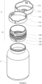
- FIG. 1 is a perspective view of the cap according to one embodiment in an open position.
- the stopper 1 comprises a first part 10 which is integral with the container 2.
- Said part 10 advantageously forms at least part of the neck of the container, and defines an outlet orifice 20 of the container.
- Said first part 10 may be an integral part of the container, as illustrated in the exploded view of the figure 7 , or be a separate part of the container 2, as illustrated in the exploded view of the figure 8 but fixed thereto in an irremovable manner.
- the part 10 is preferably rigidly connected to the container, i.e. fixed relative to the container.
- the fixing of the first part to the container may be carried out by any suitable technique, such as welding, gluing, snap-fastening, screwing, etc.
- the cap further comprises a second part 11, which comprises a fixing ring 110 and a cap 111 secured to the fixing ring by a hinge 114.
- the second part 11 is pivotally mounted on the first part 10, around a longitudinal axis X of the cap.
- the fixing ring has an internal diameter slightly greater than the external diameter of the region of the first part that it surrounds.
- the fixing ring and the first part respectively comprise at least one lug and a groove making it possible to hold the fixing ring on the first part while allowing it to pivot relative to the latter.
- the first part 10 comprises a rib 100 extending in a radial direction. Said rib delimits a circumferential groove 101, as well as a groove 102 which communicates with the groove 101 and extends towards the outlet orifice.
- the groove 102 is not oriented parallel to the X axis, but is inclined relative to said axis.
- the end of the groove 102 located on the outlet orifice side is angularly offset relative to the opposite end, which forms the junction with the groove 101.
- the groove 102 is oriented in the opposite direction to a conventional screw pitch.
- the cap 111 comprises a bottom adapted to close the outlet orifice and a side wall, of generally cylindrical shape, extending from the bottom.
- a lug 112 extends radially inwardly of the cap from the side wall.
- the lug has dimensions adapted to allow it to slide in the groove 101 and in the groove 102.
- the lug 112 is positioned in the groove 101 and retained therein in the direction of the X axis.
- the user To open the cap, the user must release the lug 112 from the groove 101 by sliding it into the groove 102, the groove 102 fulfilling the function of a means of unlocking the cap.
- the appropriate position of the second part relative to the first part to allow this unlocking is materialized by an alignment of two indicators 113, 103 arranged respectively on the second part and on the first part.
- FIGS. 2 to 4 are cutaway views at different stages of cork opening.
- the cap is in the closed position.
- the lug 112 is arranged in the groove 101.
- the indicators present respectively on the first part and the second part are angularly offset.
- the cap is in the start unlocking position, in which the lug 112 is in the groove 101, opposite the groove 102.
- the user has turned the second part relative to the first part so as to align the indicators 103, 113.
- the cap is in the end-of-unlocking position, in which the lug comes out of the groove 102, by the end opposite the groove 101.
- the user has turned the second part clockwise (which is the opposite direction to that of unscrewing) while exerting a slight pull in the X direction to engage the lug in the groove 102 and then slide it in said groove. This may involve a slight twisting of the second part, which is made possible by its plastic material construction.
- the user rotates the cap around the hinge axis, thus reaching the position of the figure 1 .
- FIG. 5 illustrates the cap open during an attempt to close it from the unlocking start position (the indicators 103, 113 being aligned).
- the portion 1000 of the rib arranged opposite the lug 112 has a shape and thickness adapted to obstruct the passage of the lug, and thus prevents the cap from closing in this position. This position is in fact not desirable for closing because, with the lug opposite the groove, the cap would no longer be locked, allowing a child to open it easily.
- the first part 10 is formed integrally with the container.
- the first part which is part of the neck of the container, may be formed by molding, and the remainder of the container by blowing.
- the first part 10 is distinct from the container, but configured to be secured to it irreversibly, for example by welding or any other suitable means.
- THE figures 9 And 10 are cross-sectional views of the cap of the figures 7 And 8 , respectively, in the closed position.
- the lug 112 has a face 1120 located on the side of the outlet orifice, which extends in a radial direction, like the face of the rib 100 which faces it. This face 1120 therefore forms a step which prevents the passage of the lug above the rib 100 and consequently prevents the opening of the cap.
- the lug 112 also has a face 1121 located on the side of the bottom of the container, which is inclined relative to the radial direction. This face 1121 therefore forms a slope suitable for sliding on the rib 100 when closing the cap.
- the cap may include other features commonly sought after in caps.
- the cap may include a seal.
- the seal may be in the form of an elastomer disk 115 arranged in the bottom of the cap. When the cap is in the closed position, said seal 115 is interposed between the end of the first part 10 and the cap 111, thus ensuring a hermetic closure of the outlet orifice 20.
- the cap may include a cover, removable when the cap is first opened.
- the cover 104 is sealed on the end of the first part 10, thus closing the outlet orifice.
- the cover advantageously comprises a tab facilitating gripping by the user for the purpose of removing the cover.
- the cap may include a reducer of the passage section, having a reduced section compared to that of the first part, in order to facilitate the dosing of the product contained in the container.
- the reducer 105 may be an integral part of the first part 10 or be secured to it by any suitable means.
Landscapes
- Engineering & Computer Science (AREA)
- Mechanical Engineering (AREA)
- Closures For Containers (AREA)
Claims (9)
- Verschluss (1) mit gesicherter Öffnung für einen Behälter (2), umfassend:- einen ersten Teil (10), der geeignet ist, fest mit dem Behälter verbunden zu sein und eine Austrittsöffnung des Behälters definiert,- einen zweiten Teil (11), der um eine Längsachse (X) des Verschlusses schwenkbar am ersten Teil (10) angebracht ist, einen Befestigungsring (110) und eine Kappe (111) umfasst, die über ein Scharnier (114) fest mit dem Befestigungsring verbunden ist, wobei der erste Teil (10) eine Rippe (100) umfasst, die eine Vertiefung (101) definiert, die sich über einen Teil des Umfangs des ersten Teils erstreckt, und eine Nut (102), die ab der Vertiefung zur Austrittsöffnung hin erstreckt,wobei die Kappe einen Vorsprung (112) umfasst, der ausgelegt ist, um in der Vertiefung (101) und in der Nut (102) zu gleiten,wobei die Nut (102) derart ausgelegt ist, dass der zweite Teil (11) des Verschlusses in Bezug auf den ersten Teil (10) handhabbar ist zwischen:- einer geschlossenen Position, in der der Vorsprung (112) in der Vertiefung (101) gehalten wird, wobei die Kappe (111) die Austrittsöffnung verschließt,- einer Entriegelungsanfangsposition, in der der Vorsprung (112) in der Vertiefung (101) der schrägen Nut (102) zugewandt positioniert ist,- einer Entriegelungsendposition, in der der Vorsprung (112) der Vertiefung (102) zugewandt auf der der Nut (101) gegenüberliegenden Seite positioniert ist, wobei die Entriegelungsendposition winkelversetzt zur Entriegelungsanfangsposition ist, und- einer geöffneten Position, in der die Kappe (111) die Austrittsöffnung freigibt, wobei der Vorsprung (112) und die Rippe (100) jeweils Formen aufweisen, die geeignet sind, ein Schließen des Verschlusses durch Einrasten des Vorsprungs (112) in die Nut (101) in jeder anderen Position als der Entriegelungsanfangsposition zu gestatten, wobei der Verschluss dadurch gekennzeichnet ist, dass ein Teil der Rippe (100), der dem Vorsprung (112) zugewandt angeordnet ist, wenn sich der Vorsprung (112) in der Entriegelungsanfangsposition befindet, eine Stufe bildet, die hoch genug ist, um den Wechsel des Vorsprungs (112) in die Nut (101) zu verhindern und so das Schließen des Verschlusses (1) zu verhindern, und wobei, wenn der Vorsprung (112) in jeder anderen Position als der Entriegelungsanfangsposition ist, die Flächen des Vorsprungs (112) und der Rippe (100), die sich gegenüberliegen, wenn der Verschluss (1) in der geöffneten Position ist, jeweilige Neigungen aufweisen, die das Gleiten der Flächen übereinander in Verbindung mit einer elastischen Verformung der Kappe (111) bis zum Einführen des Vorsprungs (112) in die Nut (101) begünstigen.
- Verschluss nach Anspruch 1, wobei der erste Teil (10) fester Bestandteil des Behälters (2) ist.
- Verschluss nach Anspruch 1, wobei der erste Teil (10) vom Behälter getrennt und geeignet ist, starr am Behälter befestigt zu sein.
- Verschluss nach einem der Ansprüche 1 bis 3, wobei das Scharnier einen Gelenkbolzen umfasst, der den Befestigungsring und die Kappe verbindet.
- Verschluss nach einem der Ansprüche 1 bis 3, wobei das Scharnier ein fester Bestandteil des Befestigungsrings (110) und der Kappe (111) ist.
- Verschluss nach einem der Ansprüche 1 bis 5, wobei der erste Teil und der zweite Teil jeweils einen ersten und einen zweiten Indikator (103, 113) umfassen, die so eingerichtet sind, dass die Indikatoren ausgerichtet sind, wenn sich der zweite Teil (11) in der Entriegelungsanfangsposition befindet.
- Verschluss nach einem der Ansprüche 1 bis 6, ferner umfassend eine Dichtung (115), die zwischen dem ersten Teil und dem zweiten Teil angeordnet ist.
- Verschluss nach einem der Ansprüche 1 bis 7, wobei der erste Teil von einem Deckel (104) verschlossen ist.
- Verschluss nach einem der Ansprüche 1 bis 8, wobei der erste Teil mit einem Reduzierer (105) des Querschnitts der Austrittsöffnung versehen ist.
Applications Claiming Priority (2)
| Application Number | Priority Date | Filing Date | Title |
|---|---|---|---|
| FR1908530A FR3099142B1 (fr) | 2019-07-26 | 2019-07-26 | Bouchon à ouverture sécurisée |
| PCT/FR2020/051346 WO2021019161A1 (fr) | 2019-07-26 | 2020-07-23 | Bouchon à ouverture sécurisée |
Publications (3)
| Publication Number | Publication Date |
|---|---|
| EP4003866A1 EP4003866A1 (de) | 2022-06-01 |
| EP4003866C0 EP4003866C0 (de) | 2024-09-18 |
| EP4003866B1 true EP4003866B1 (de) | 2024-09-18 |
Family
ID=68987834
Family Applications (1)
| Application Number | Title | Priority Date | Filing Date |
|---|---|---|---|
| EP20754008.9A Active EP4003866B1 (de) | 2019-07-26 | 2020-07-23 | Sicherheitsverschluss |
Country Status (4)
| Country | Link |
|---|---|
| EP (1) | EP4003866B1 (de) |
| ES (1) | ES2992178T3 (de) |
| FR (1) | FR3099142B1 (de) |
| WO (1) | WO2021019161A1 (de) |
Cited By (1)
| Publication number | Priority date | Publication date | Assignee | Title |
|---|---|---|---|---|
| EP4722123A1 (de) * | 2024-10-03 | 2026-04-08 | Easy Plast S.r.l. | Öffnungs-/schliessvorrichtung für einen behälter mit fliessenden produkten |
Families Citing this family (17)
| Publication number | Priority date | Publication date | Assignee | Title |
|---|---|---|---|---|
| US11647860B1 (en) | 2022-05-13 | 2023-05-16 | Sharkninja Operating Llc | Flavored beverage carbonation system |
| US12213617B2 (en) | 2022-05-13 | 2025-02-04 | Sharkninja Operating Llc | Flavored beverage carbonation process |
| US12096880B2 (en) | 2022-05-13 | 2024-09-24 | Sharkninja Operating Llc | Flavorant for beverage carbonation system |
| US11751585B1 (en) | 2022-05-13 | 2023-09-12 | Sharkninja Operating Llc | Flavored beverage carbonation system |
| US12539500B2 (en) | 2022-08-31 | 2026-02-03 | Sharkninja Operating Llc | Additive containers |
| US12103840B2 (en) | 2022-11-17 | 2024-10-01 | Sharkninja Operating Llc | Ingredient container with sealing valve |
| US11634314B1 (en) | 2022-11-17 | 2023-04-25 | Sharkninja Operating Llc | Dosing accuracy |
| US12084334B2 (en) | 2022-11-17 | 2024-09-10 | Sharkninja Operating Llc | Ingredient container |
| US11738988B1 (en) | 2022-11-17 | 2023-08-29 | Sharkninja Operating Llc | Ingredient container valve control |
| US11745996B1 (en) | 2022-11-17 | 2023-09-05 | Sharkninja Operating Llc | Ingredient containers for use with beverage dispensers |
| USD1091308S1 (en) | 2022-12-23 | 2025-09-02 | Sharkninja Operating Llc | Ingredient container |
| USD1092208S1 (en) | 2022-12-23 | 2025-09-09 | Sharkninja Operating Llc | Cap of ingredient container |
| US12116257B1 (en) | 2023-03-22 | 2024-10-15 | Sharkninja Operating Llc | Adapter for beverage dispenser |
| US11871867B1 (en) | 2023-03-22 | 2024-01-16 | Sharkninja Operating Llc | Additive container with bottom cover |
| US11925287B1 (en) | 2023-03-22 | 2024-03-12 | Sharkninja Operating Llc | Additive container with inlet tube |
| US12005408B1 (en) | 2023-04-14 | 2024-06-11 | Sharkninja Operating Llc | Mixing funnel |
| KR20250061350A (ko) * | 2023-10-27 | 2025-05-08 | 김윤희 | 양방향 잠금형 원터치 캡 |
Family Cites Families (7)
| Publication number | Priority date | Publication date | Assignee | Title |
|---|---|---|---|---|
| US3822027A (en) * | 1973-01-08 | 1974-07-02 | S Cherba | Container with safety cap |
| US5065876A (en) * | 1989-12-04 | 1991-11-19 | Joyce Molding Corp. | Child-proof container and flip-top closure for dry or for liquid contents |
| US5316162A (en) | 1992-11-13 | 1994-05-31 | Pierson Industries, Inc. | Universally adaptable childproof cap |
| US5520305A (en) | 1995-03-29 | 1996-05-28 | Pierson Industries, Inc. | Container and two piece safety cap having a locking collar and cover |
| US5765705A (en) * | 1996-07-30 | 1998-06-16 | Poly-Seal Corporation | Child resistant closure |
| US6431380B1 (en) * | 1999-10-21 | 2002-08-13 | Rexam Medical Packaging Inc. | Child-resistant flip top closure |
| JP2003063553A (ja) * | 2001-08-21 | 2003-03-05 | Yoshino Kogyosho Co Ltd | ヒンジキャップ |
-
2019
- 2019-07-26 FR FR1908530A patent/FR3099142B1/fr active Active
-
2020
- 2020-07-23 WO PCT/FR2020/051346 patent/WO2021019161A1/fr not_active Ceased
- 2020-07-23 EP EP20754008.9A patent/EP4003866B1/de active Active
- 2020-07-23 ES ES20754008T patent/ES2992178T3/es active Active
Cited By (1)
| Publication number | Priority date | Publication date | Assignee | Title |
|---|---|---|---|---|
| EP4722123A1 (de) * | 2024-10-03 | 2026-04-08 | Easy Plast S.r.l. | Öffnungs-/schliessvorrichtung für einen behälter mit fliessenden produkten |
Also Published As
| Publication number | Publication date |
|---|---|
| EP4003866C0 (de) | 2024-09-18 |
| WO2021019161A1 (fr) | 2021-02-04 |
| FR3099142B1 (fr) | 2021-08-06 |
| FR3099142A1 (fr) | 2021-01-29 |
| EP4003866A1 (de) | 2022-06-01 |
| ES2992178T3 (es) | 2024-12-10 |
Similar Documents
| Publication | Publication Date | Title |
|---|---|---|
| EP4003866B1 (de) | Sicherheitsverschluss | |
| EP0538094B1 (de) | Metallbehälter, der entlang einer Schwächungslinie teilweise geöffnet werden kann | |
| EP0633197B1 (de) | Kombination von Behälter und Verschluss, die sich durch relative Rotation miteinander verriegeln sowie deren Verwendung | |
| EP2326560B1 (de) | Behälter mit einer dichten öffnungs- und schliessvorrichtung | |
| EP0761558B1 (de) | Vorrichtung zum Verschliessen eines Behälters und zur Abgabe des Behälterinhalts | |
| FR2688197A1 (fr) | Fermeture distributrice a collier de basculement. | |
| FR3108317A3 (fr) | Bouchon pour recipient a col filete muni d’un organe de blocage par engagement | |
| FR2933675A1 (fr) | Element de fermeture d'un recipient en particulier fait dans un materiau de type feuille | |
| EP0641721A1 (de) | Schraubkappe mit Originalitäts-Sicherungsband, mit solcher Kappe versehene Verpackung, Verfahren zur Herstellung einer solchen Kappe und solche Verpackung | |
| EP3882173B1 (de) | Scharnierdeckel für einen behälter mit einem hals | |
| EP0583204A1 (de) | Ausgiesskappe mit schwenkbarem Verschluss | |
| EP3882172A1 (de) | Kappe für einen behälter mit einem gewindehals, der mit einem blockierorgan durch drücken versehen ist | |
| EP4026783B1 (de) | Verschlussvorrichtung zur befestigung am hals eines behälters | |
| FR2834276A1 (fr) | Dispositif de bouchage et recipient pourvu d'un tel dispositif | |
| EP3889063B1 (de) | Zusammenstellung mit behälter mit gewindehals und kappe mit achsenpositionierungsbeinen und zentrierbeinen | |
| EP0373989B1 (de) | Behälterverschlusskappe mit schwenkbarem Betätigungselement zum Abgeben des Behälterinhalts | |
| FR2676997A1 (fr) | Bouchon-service a l'epreuve des enfants. | |
| EP4026782B1 (de) | Verschlussvorrichtung zur befestigung am hals eines behälters | |
| FR2715384A1 (fr) | Ensemble comprenant un récipient rechargeable en un produit tel une crème cosmétique et son bouchon. | |
| FR2486914A1 (fr) | Recipient a fermeture de securite | |
| EP0739826B1 (de) | Verschlussvorrichtung mit einer seitlichen, axial ausziehbaren Oeffnung | |
| EP0648683A1 (de) | Verschlussvorrichtung für einen mit einem Hals versehenen flaschen- oder topfförmigen Behälter | |
| FR2715381A1 (fr) | Récipient muni d'une capsule de fermeture inviolable. | |
| EP4147985B1 (de) | Vorrichtung zur lagerung einer flüssigkeit mit einem behälter und einem stopfen, der fest mit dem behälter verbunden bleibt | |
| WO2009056769A1 (fr) | Dispositif de bouchage d'un col de récipient |
Legal Events
| Date | Code | Title | Description |
|---|---|---|---|
| STAA | Information on the status of an ep patent application or granted ep patent |
Free format text: STATUS: UNKNOWN |
|
| STAA | Information on the status of an ep patent application or granted ep patent |
Free format text: STATUS: THE INTERNATIONAL PUBLICATION HAS BEEN MADE |
|
| PUAI | Public reference made under article 153(3) epc to a published international application that has entered the european phase |
Free format text: ORIGINAL CODE: 0009012 |
|
| STAA | Information on the status of an ep patent application or granted ep patent |
Free format text: STATUS: REQUEST FOR EXAMINATION WAS MADE |
|
| 17P | Request for examination filed |
Effective date: 20220221 |
|
| AK | Designated contracting states |
Kind code of ref document: A1 Designated state(s): AL AT BE BG CH CY CZ DE DK EE ES FI FR GB GR HR HU IE IS IT LI LT LU LV MC MK MT NL NO PL PT RO RS SE SI SK SM TR |
|
| DAV | Request for validation of the european patent (deleted) | ||
| DAX | Request for extension of the european patent (deleted) | ||
| GRAP | Despatch of communication of intention to grant a patent |
Free format text: ORIGINAL CODE: EPIDOSNIGR1 |
|
| STAA | Information on the status of an ep patent application or granted ep patent |
Free format text: STATUS: GRANT OF PATENT IS INTENDED |
|
| INTG | Intention to grant announced |
Effective date: 20240606 |
|
| GRAS | Grant fee paid |
Free format text: ORIGINAL CODE: EPIDOSNIGR3 |
|
| GRAA | (expected) grant |
Free format text: ORIGINAL CODE: 0009210 |
|
| STAA | Information on the status of an ep patent application or granted ep patent |
Free format text: STATUS: THE PATENT HAS BEEN GRANTED |
|
| AK | Designated contracting states |
Kind code of ref document: B1 Designated state(s): AL AT BE BG CH CY CZ DE DK EE ES FI FR GB GR HR HU IE IS IT LI LT LU LV MC MK MT NL NO PL PT RO RS SE SI SK SM TR |
|
| REG | Reference to a national code |
Ref country code: GB Ref legal event code: FG4D Free format text: NOT ENGLISH |
|
| REG | Reference to a national code |
Ref country code: CH Ref legal event code: EP |
|
| REG | Reference to a national code |
Ref country code: DE Ref legal event code: R096 Ref document number: 602020037959 Country of ref document: DE |
|
| REG | Reference to a national code |
Ref country code: IE Ref legal event code: FG4D Free format text: LANGUAGE OF EP DOCUMENT: FRENCH |
|
| U01 | Request for unitary effect filed |
Effective date: 20241017 |
|
| U07 | Unitary effect registered |
Designated state(s): AT BE BG DE DK EE FI FR IT LT LU LV MT NL PT RO SE SI Effective date: 20241031 |
|
| REG | Reference to a national code |
Ref country code: ES Ref legal event code: FG2A Ref document number: 2992178 Country of ref document: ES Kind code of ref document: T3 Effective date: 20241210 |
|
| PG25 | Lapsed in a contracting state [announced via postgrant information from national office to epo] |
Ref country code: NO Free format text: LAPSE BECAUSE OF FAILURE TO SUBMIT A TRANSLATION OF THE DESCRIPTION OR TO PAY THE FEE WITHIN THE PRESCRIBED TIME-LIMIT Effective date: 20241218 |
|
| PG25 | Lapsed in a contracting state [announced via postgrant information from national office to epo] |
Ref country code: GR Free format text: LAPSE BECAUSE OF FAILURE TO SUBMIT A TRANSLATION OF THE DESCRIPTION OR TO PAY THE FEE WITHIN THE PRESCRIBED TIME-LIMIT Effective date: 20241219 |
|
| PG25 | Lapsed in a contracting state [announced via postgrant information from national office to epo] |
Ref country code: HR Free format text: LAPSE BECAUSE OF FAILURE TO SUBMIT A TRANSLATION OF THE DESCRIPTION OR TO PAY THE FEE WITHIN THE PRESCRIBED TIME-LIMIT Effective date: 20240918 |
|
| PG25 | Lapsed in a contracting state [announced via postgrant information from national office to epo] |
Ref country code: RS Free format text: LAPSE BECAUSE OF FAILURE TO SUBMIT A TRANSLATION OF THE DESCRIPTION OR TO PAY THE FEE WITHIN THE PRESCRIBED TIME-LIMIT Effective date: 20241218 |
|
| PG25 | Lapsed in a contracting state [announced via postgrant information from national office to epo] |
Ref country code: RS Free format text: LAPSE BECAUSE OF FAILURE TO SUBMIT A TRANSLATION OF THE DESCRIPTION OR TO PAY THE FEE WITHIN THE PRESCRIBED TIME-LIMIT Effective date: 20241218 Ref country code: NO Free format text: LAPSE BECAUSE OF FAILURE TO SUBMIT A TRANSLATION OF THE DESCRIPTION OR TO PAY THE FEE WITHIN THE PRESCRIBED TIME-LIMIT Effective date: 20241218 Ref country code: HR Free format text: LAPSE BECAUSE OF FAILURE TO SUBMIT A TRANSLATION OF THE DESCRIPTION OR TO PAY THE FEE WITHIN THE PRESCRIBED TIME-LIMIT Effective date: 20240918 Ref country code: GR Free format text: LAPSE BECAUSE OF FAILURE TO SUBMIT A TRANSLATION OF THE DESCRIPTION OR TO PAY THE FEE WITHIN THE PRESCRIBED TIME-LIMIT Effective date: 20241219 |
|
| PG25 | Lapsed in a contracting state [announced via postgrant information from national office to epo] |
Ref country code: IS Free format text: LAPSE BECAUSE OF FAILURE TO SUBMIT A TRANSLATION OF THE DESCRIPTION OR TO PAY THE FEE WITHIN THE PRESCRIBED TIME-LIMIT Effective date: 20250118 |
|
| PG25 | Lapsed in a contracting state [announced via postgrant information from national office to epo] |
Ref country code: SM Free format text: LAPSE BECAUSE OF FAILURE TO SUBMIT A TRANSLATION OF THE DESCRIPTION OR TO PAY THE FEE WITHIN THE PRESCRIBED TIME-LIMIT Effective date: 20240918 |
|
| PG25 | Lapsed in a contracting state [announced via postgrant information from national office to epo] |
Ref country code: PL Free format text: LAPSE BECAUSE OF FAILURE TO SUBMIT A TRANSLATION OF THE DESCRIPTION OR TO PAY THE FEE WITHIN THE PRESCRIBED TIME-LIMIT Effective date: 20240918 Ref country code: CZ Free format text: LAPSE BECAUSE OF FAILURE TO SUBMIT A TRANSLATION OF THE DESCRIPTION OR TO PAY THE FEE WITHIN THE PRESCRIBED TIME-LIMIT Effective date: 20240918 |
|
| PG25 | Lapsed in a contracting state [announced via postgrant information from national office to epo] |
Ref country code: SK Free format text: LAPSE BECAUSE OF FAILURE TO SUBMIT A TRANSLATION OF THE DESCRIPTION OR TO PAY THE FEE WITHIN THE PRESCRIBED TIME-LIMIT Effective date: 20240918 |
|
| U20 | Renewal fee for the european patent with unitary effect paid |
Year of fee payment: 6 Effective date: 20250616 |
|
| PLBE | No opposition filed within time limit |
Free format text: ORIGINAL CODE: 0009261 |
|
| STAA | Information on the status of an ep patent application or granted ep patent |
Free format text: STATUS: NO OPPOSITION FILED WITHIN TIME LIMIT |
|
| 26N | No opposition filed |
Effective date: 20250619 |
|
| PGFP | Annual fee paid to national office [announced via postgrant information from national office to epo] |
Ref country code: ES Payment date: 20250811 Year of fee payment: 6 |
|
| PGFP | Annual fee paid to national office [announced via postgrant information from national office to epo] |
Ref country code: GB Payment date: 20250723 Year of fee payment: 6 |
|
| REG | Reference to a national code |
Ref country code: CH Ref legal event code: H13 Free format text: ST27 STATUS EVENT CODE: U-0-0-H10-H13 (AS PROVIDED BY THE NATIONAL OFFICE) Effective date: 20260224 |