EP4003889B1 - Procédé d'enroulement d'une bande de non-tissés de laine minérale et appareil pour effectuer le procédé - Google Patents
Procédé d'enroulement d'une bande de non-tissés de laine minérale et appareil pour effectuer le procédé Download PDFInfo
- Publication number
- EP4003889B1 EP4003889B1 EP20743682.5A EP20743682A EP4003889B1 EP 4003889 B1 EP4003889 B1 EP 4003889B1 EP 20743682 A EP20743682 A EP 20743682A EP 4003889 B1 EP4003889 B1 EP 4003889B1
- Authority
- EP
- European Patent Office
- Prior art keywords
- winding
- wound roll
- web
- monitoring
- mineral wool
- Prior art date
- Legal status (The legal status is an assumption and is not a legal conclusion. Google has not performed a legal analysis and makes no representation as to the accuracy of the status listed.)
- Active
Links
Images


Classifications
-
- B—PERFORMING OPERATIONS; TRANSPORTING
- B65—CONVEYING; PACKING; STORING; HANDLING THIN OR FILAMENTARY MATERIAL
- B65H—HANDLING THIN OR FILAMENTARY MATERIAL, e.g. SHEETS, WEBS, CABLES
- B65H18/00—Winding webs
- B65H18/08—Web-winding mechanisms
- B65H18/14—Mechanisms in which power is applied to web roll, e.g. to effect continuous advancement of web
- B65H18/22—Mechanisms in which power is applied to web roll, e.g. to effect continuous advancement of web by friction band
-
- B—PERFORMING OPERATIONS; TRANSPORTING
- B65—CONVEYING; PACKING; STORING; HANDLING THIN OR FILAMENTARY MATERIAL
- B65H—HANDLING THIN OR FILAMENTARY MATERIAL, e.g. SHEETS, WEBS, CABLES
- B65H18/00—Winding webs
- B65H18/08—Web-winding mechanisms
- B65H18/26—Mechanisms for controlling contact pressure on winding-web package, e.g. for regulating the quantity of air between web layers
-
- B—PERFORMING OPERATIONS; TRANSPORTING
- B65—CONVEYING; PACKING; STORING; HANDLING THIN OR FILAMENTARY MATERIAL
- B65B—MACHINES, APPARATUS OR DEVICES FOR, OR METHODS OF, PACKAGING ARTICLES OR MATERIALS; UNPACKING
- B65B57/00—Automatic control, checking, warning, or safety devices
- B65B57/10—Automatic control, checking, warning, or safety devices responsive to absence, presence, abnormal feed, or misplacement of articles or materials to be packaged
- B65B57/14—Automatic control, checking, warning, or safety devices responsive to absence, presence, abnormal feed, or misplacement of articles or materials to be packaged and operating to control, or stop, the feed of articles or material to be packaged
-
- B—PERFORMING OPERATIONS; TRANSPORTING
- B65—CONVEYING; PACKING; STORING; HANDLING THIN OR FILAMENTARY MATERIAL
- B65B—MACHINES, APPARATUS OR DEVICES FOR, OR METHODS OF, PACKAGING ARTICLES OR MATERIALS; UNPACKING
- B65B63/00—Auxiliary devices, not otherwise provided for, for operating on articles or materials to be packaged
- B65B63/02—Auxiliary devices, not otherwise provided for, for operating on articles or materials to be packaged for compressing or compacting articles or materials prior to wrapping or insertion in containers or receptacles
- B65B63/024—Auxiliary devices, not otherwise provided for, for operating on articles or materials to be packaged for compressing or compacting articles or materials prior to wrapping or insertion in containers or receptacles for compressing by winding
-
- B—PERFORMING OPERATIONS; TRANSPORTING
- B65—CONVEYING; PACKING; STORING; HANDLING THIN OR FILAMENTARY MATERIAL
- B65H—HANDLING THIN OR FILAMENTARY MATERIAL, e.g. SHEETS, WEBS, CABLES
- B65H2301/00—Handling processes for sheets or webs
- B65H2301/40—Type of handling process
- B65H2301/41—Winding, unwinding
- B65H2301/413—Supporting web roll
- B65H2301/4137—Supporting web roll on its outer circumference
- B65H2301/4138—Supporting web roll on its outer circumference belt arrangement
-
- B—PERFORMING OPERATIONS; TRANSPORTING
- B65—CONVEYING; PACKING; STORING; HANDLING THIN OR FILAMENTARY MATERIAL
- B65H—HANDLING THIN OR FILAMENTARY MATERIAL, e.g. SHEETS, WEBS, CABLES
- B65H2511/00—Dimensions; Position; Numbers; Identification; Occurrences
- B65H2511/10—Size; Dimensions
- B65H2511/15—Height, e.g. of stack
-
- B—PERFORMING OPERATIONS; TRANSPORTING
- B65—CONVEYING; PACKING; STORING; HANDLING THIN OR FILAMENTARY MATERIAL
- B65H—HANDLING THIN OR FILAMENTARY MATERIAL, e.g. SHEETS, WEBS, CABLES
- B65H2511/00—Dimensions; Position; Numbers; Identification; Occurrences
- B65H2511/10—Size; Dimensions
- B65H2511/16—Irregularities, e.g. protuberances
- B65H2511/166—Irregularities, e.g. protuberances relative to diameter, eccentricity or circularity
-
- B—PERFORMING OPERATIONS; TRANSPORTING
- B65—CONVEYING; PACKING; STORING; HANDLING THIN OR FILAMENTARY MATERIAL
- B65H—HANDLING THIN OR FILAMENTARY MATERIAL, e.g. SHEETS, WEBS, CABLES
- B65H2553/00—Sensing or detecting means
- B65H2553/40—Sensing or detecting means using optical, e.g. photographic, elements
- B65H2553/42—Cameras
-
- B—PERFORMING OPERATIONS; TRANSPORTING
- B65—CONVEYING; PACKING; STORING; HANDLING THIN OR FILAMENTARY MATERIAL
- B65H—HANDLING THIN OR FILAMENTARY MATERIAL, e.g. SHEETS, WEBS, CABLES
- B65H2701/00—Handled material; Storage means
- B65H2701/10—Handled articles or webs
- B65H2701/17—Nature of material
- B65H2701/177—Fibrous or compressible material
-
- B—PERFORMING OPERATIONS; TRANSPORTING
- B65—CONVEYING; PACKING; STORING; HANDLING THIN OR FILAMENTARY MATERIAL
- B65H—HANDLING THIN OR FILAMENTARY MATERIAL, e.g. SHEETS, WEBS, CABLES
- B65H2701/00—Handled material; Storage means
- B65H2701/10—Handled articles or webs
- B65H2701/18—Form of handled article or web
- B65H2701/184—Wound packages
- B65H2701/1842—Wound packages of webs
- B65H2701/18422—Coreless
-
- B—PERFORMING OPERATIONS; TRANSPORTING
- B65—CONVEYING; PACKING; STORING; HANDLING THIN OR FILAMENTARY MATERIAL
- B65H—HANDLING THIN OR FILAMENTARY MATERIAL, e.g. SHEETS, WEBS, CABLES
- B65H2701/00—Handled material; Storage means
- B65H2701/10—Handled articles or webs
- B65H2701/18—Form of handled article or web
- B65H2701/184—Wound packages
- B65H2701/1846—Parts concerned
-
- B—PERFORMING OPERATIONS; TRANSPORTING
- B65—CONVEYING; PACKING; STORING; HANDLING THIN OR FILAMENTARY MATERIAL
- B65H—HANDLING THIN OR FILAMENTARY MATERIAL, e.g. SHEETS, WEBS, CABLES
- B65H2701/00—Handled material; Storage means
- B65H2701/10—Handled articles or webs
- B65H2701/19—Specific article or web
- B65H2701/1922—Specific article or web for covering surfaces such as carpets, roads, roofs or walls
Definitions
- the invention relates to a method for, in particular, the coreless winding-up of a web of mineral wool nonwovens, in particular of compressible mineral wool nonwovens and an apparatus for carrying out the method.
- An apparatus for rolling up compressible fibrous materials is known from DE 698 00 627 T2 .
- Such an apparatus has a winding-up space in which a coreless wound roll is formed from the compressible fibrous material.
- the compressible fibrous material is provided in the form of webs and is moved toward the winding-up space by a first conveying means.
- a pre-pressing device Opposite the first conveying means and upstream of the winding-up space a pre-pressing device is provided by means of which the band-shaped fibrous material is compressible from a first thickness in conveying direction upstream of the pre-pressing device to a second (thinner) thickness downstream of the pre-pressing device.
- a second conveying means is provided which is arranged in tangential engagement against the winding-up roller and in an angle to the first conveying means.
- a restricting member e.g., a roller, is provided, which, together with the two conveying means, forms the winding-up space.
- the restricting member is designed to be movable along a straight line (angle bisector of the conveying means) relative to the roll being formed and to be drivable by a motor. It is known from this publication that a distance D between the circumference of the roll to be wound up and the pre-pressing device is to be maintained substantially unchanged.
- the diameter of the wound roll is determined by means of suitable sensors and the pre-pressing device is displaced during the winding-up process according to the expanding wound roll such that the distance D remains as constant as possible.
- Such an apparatus does not allow for setting the distance D of the pre-pressing device depending on a winding quality of the wound roll.
- an apparatus and a method for determining a distance measurement on wound-up materials is known from EP 2 328 746 B1 .
- a material wound onto a roll is illuminated by a light source, in particular a laser light source.
- a resulting height pattern on the web-type wound material is captured and analyzed by an image-capturing device (camera).
- a method for producing a web of tissue material is known from DE 102 18 509 A1 .
- a web of tissue material is guided through a press nip formed between a drying cylinder and an opposing unit. Downstream of the press nip, the web of tissue material is wound up by means of a winding-up device, wherein the hardness of the resulting roll can be influenced, in particular controlled and/or regulated, in a predeterminable manner.
- monitoring the winding nip area by means of a CCT camera is provided.
- the distance between the carrier drum and the tambour or the roll formed thereon is captured. Monitoring the area of the winding nip in this way provides a means for checking and adjusting the winding force. By evaluating such an image, a target value for the pressure of the hydraulic cylinder affecting the displaceable wound roll can be reached.
- WO 99/01365 A1 shows a method of monitoring a tension of a tensioning belt during the winding of tissue sheets.
- JP 2014-213952A teaches a method for determining an eccentricity of a wound roll of paper.
- EP 2 319 787 A2 teaches a method and apparatus for controlling the slitting of a web-like material by positioning a monitoring area dependent of a changed position of a fixed point.
- US 2005/0156078 A1 discloses a winding apparatus for winding a paper web and indirect monitoring of a radius of a roll using a projected laser beam.
- EP 2 837 588 A2 discloses an apparatus and a method for rolling a carpet or a rug in which a sensor element being part of the apparatus detects a certain property of the carpet (pile direction) and a movement of the element is monitored.
- JP 2000-105104 A discloses an eccentricity inspection device which measures the eccentricity of rolls of paper to prevent the occurrence of artificial errors by making measurement mechanically and to smoothly inspect the rolls of paper by conducting inspections in a non-contacting state.
- the invention is concerned specifically, with winding up webs of fibrous insulating material, and more specifically with winding up webs of mineral wool nonwovens (glass wool and/or stone wool).
- the fibers are present in a particular preferred direction and are bonded by a bonding agent.
- the nonwoven suffers unavoidable minor damage.
- the winding-up process must be controlled accordingly. Up until now, this is being done by the machine operator. He looks at the wound-up web and adjusts certain process parameters based on his experience.
- the method is intended to provide a quality-optimized winding result, wherein the method is intended to be automatically driven so that the method makes the active intervention of a machine operator practically unnecessary.
- a method according to the present invention for winding up a web of mineral wool nonwovens by means of an apparatus having stationary and mobile devices, said apparatus having a winding-up space for accommodating an at least partially wound roll having a winding center and means for conveying and/or for manipulating the web of mineral wool nonwovens prior to and during winding-up, comprises the following steps:
- the target state is stored in a database.
- the method according to the invention allows for the improvement of the winding quality of a wound roll formed from, in particular, a compressible material, wherein in particular a consistent final diameter of the wound roll is achievable. Furthermore, a level of compression/compaction of the web of mineral wool nonwovens is highly consistent over the entire length of the wound web. It is possible to ensure that a winding center of the wound web of mineral wool nonwovens is to a large extent arranged centrically relative to the circumference of the wound roll. Last but not least, it is ensured that a circumference of the wound roll is to a large extent (except for a change in material thickness) (cf. Fig. 3 ) circular.
- the monitoring of the web of mineral wool nonwovens and the wound roll is carried out individually or cumulatively at the locations listed below:
- the specified monitoring locations i.e., the localized main monitoring areas, have proven particularly effective for detecting the circumference of the wound roll and a web form of the web of mineral wool nonwovens.
- the comparing of the actual state to the target state is carried out by comparing actual circumferential contours to target circumferential contours of the wound roll and/or the web of mineral wool nonwovens.
- At least one operating parameter selected from the following operating parameters is corrected and/or adjusted to reduce the determined deviations:
- the specified operating parameters of the apparatus allow for counteracting an unintentional deviation between various actual and target states in a particularly effective manner.
- the monitoring, comparing and/or correcting are continuous.
- an average value of multiple, chronologically successive actual states is used for the comparison.
- an average value of multiple discrete actual states i.e., in particular, discrete monitoring time points, may be used for the comparison. This helps to reduce the required computing power or to reduce the calculation time for a given computing power of a controller.
- the operating parameter is corrected/adjusted if:
- monitoring the web of mineral wool nonwovens and/or the resulting wound roll by means of at least one image-capturing device additionally comprises monitoring at least part of the apparatus, in particular at least part of the mobile devices.
- This measure which is to be carried out in addition to feature b) of claim 1, can be used to make better predictions of errors regarding the winding result and/or to check adjustments or modifications made to the apparatus or its stationary and/or mobile devices and to monitor and, if necessary, analyze their effects on winding quality.
- an apparatus for carrying out the above-named method said apparatus having:
- This apparatus provides a simple means for carrying out the method. In particular, only few hardware monitoring means are required. In the simplest case, an inexpensive digital camera and a computing device are sufficient.
- a preferred embodiment of the apparatus according to the present invention has a memory at least for storing image data regarding target states of the apparatus or the wound roll.
- the apparatus itself has a memory for such target states.
- a memory may also be provided outside of the apparatus.
- An apparatus 1 for carrying out the method according to the invention has an open winding-up space 2 for accommodating a wound-up roll of mineral wool nonwovens web (wound roll 3).
- the wound roll 3 is, in particular, wound up coreless, i.e., the wound roll 3 does not contain any rigid body around which the web of mineral wool nonwovens 4 to be wound up is wound up.
- the apparatus 1 further comprises means for conveying and/or for manipulating the web of mineral wool nonwovens 4, said means mechanically acting on the web of mineral wool nonwovens 4 prior to and during winding-up or on the resulting wound roll 3.
- the apparatus 1 comprises a first conveying means 5 which is, in particular, formed as a belt conveyor having a conveyor belt 6.
- the web of mineral wool nonwovens 4 is placed on a loaded side 7 of the conveyor belt 6 with the loaded side 7 moving in the depicted direction of the arrow (conveying direction) with a conveying speed v 1 .
- a second conveying means 8 is also configured as a belt conveyor having a conveyor belt 9.
- a loaded side 10 of the second conveying means 8 moves in the depicted direction of the arrow (conveying direction) with a conveying speed v 2 .
- the first loaded side 6 and the second loaded side 10 form an angle ⁇ to each other and each encloses a part of the winding-up space 2.
- the apparatus 1 Positioned upstream of the winding-up space 2 in the conveying direction (direction of speed v 1 ) of the web of mineral wool nonwovens 4, the apparatus 1 has a pre-pressing device 11.
- the pre-pressing device 11 has a belt conveyor 12 and a pre-pressing bar 13.
- the pre-pressing bar 13 has a free end edge 14, which faces towards wound roll 3.
- the free end edge 14 is displaceable in an X-direction (double arrow 15) and in a Z-direction (double arrow 16) relative to the winding-up space and the loaded side 7 of the first conveying means, respectively.
- the displacement may be adapted to be motor-drivable.
- an angle ⁇ between the belt conveyor 12 of the pre-pressing device 11 and the loaded side 7 of the first conveying means is adjustable, in particular, adjustable by means of a motor.
- the displacement of the pre-pressing device 11 in the direction of the double arrow 16 results in a height h of a pre-pressing nip 17 (cf. Fig. 2a ) between the pre-pressing bar 13 and the conveyor belt 6 of the first conveying means 5.
- the apparatus 1 comprises a motor-driven winding-up roller 18, the axis of rotation of which is disposed approximately on the angle bisector of angle ⁇ .
- the winding-up roller 18 is attached to a winding arm 19, which is pivotably arranged about a pivot axis 20 and is arranged to be, in particular, adjustable by a motor.
- the conveying means 5, 8 are stationary in the double-arrow directions 15, 16 during the winding process. If required, the angle ⁇ between the loaded sides 7 and 10 is variably adjustable and, if applicable, adjustable by a motor.
- the pivot axis 20 is movable in the direction of double arrow 16.
- the winding-up roller 18 is motor-drivable about its axis and arranged such that said winding-up roller in contact with a circumference U of the wound roll 3 of the web of mineral wool nonwovens 4 already wound up and is pivotable about the axis 20 with the expanding wound roll 3.
- the contact pressure (force F) of the winding-up roller 18 onto the circumference of the wound roll 3 is adjustable by means of the winding arm 19.
- the first loaded side 7, the second loaded side 10 and the winding-up roller 18 define the winding-up space 2 for the wound roll 3 being formed.
- monitoring areas in the vicinity of the wound roll 3 in particular are of great interest. These monitoring areas are marked with the letters A, B, C in the figures. By monitoring these monitoring areas A, B, C, substantiated statements about the winding quality of the wound roll 3 can be made.
- the web of mineral wool nonwovens 4 is, for example, a web of mineral wool nonwovens made of fibrous, compressible mineral wool nonwovens such as a web of insulating fibrous mineral wool nonwovens. Nevertheless, all webs of mineral wool nonwovens that are compressible in a thickness direction can be processed with the apparatus according to the present invention.
- the apparatus 1 has at least one image-capturing device 30 arranged in the space and aligned in regard to its line of sight such that in particular the monitoring areas A, B, C can be monitored.
- the image-capturing device 30 may be, for example, a CCD camera or any other image-capturing device 30 that preferably provides electronic image data.
- the at least one image-capturing device 30 may be aligned so as to monitor additional or alternative portions of the apparatus outside of the monitoring areas A, B, C.
- the above mentioned additional or alternatively performed monitoring of portions of the apparatus outside of the monitoring areas A, B, C serves to carry out any apparatus-specific monitoring measures, for example, whether an automatically adjusted correction of a parameter has actually been set.
- Such additional monitoring of the apparatus itself or of individual devices of the apparatus may take place in addition to monitoring the web of mineral wool nonwovens and/or the wound roll being formed according to feature b), so that the inventive effect is achieved when either the web of mineral wool nonwovens and/or the wound roll being formed, or the web of mineral wool nonwovens and/or the wound roll being formed and the apparatus or the devices of said apparatus are being monitored.
- the image-capturing device 30 is connected to at least one analyzing unit 40 which compares image information of actual states of the wound roll 3 to stored target states of the wound roll 3 and determines deviations between these states.
- the apparatus 1 expediently has a memory 45 which holds necessary data regarding target states and provides said data to the analyzing unit 40, when necessary.
- the apparatus has at least one correcting unit 50 which determines from the deviations determined by the analyzing unit 40 necessary corrections of at least one operating parameter of the apparatus 1.
- the correcting unit 50 causes means for setting the at least one corresponding operating parameter on the apparatus to modify the associated operating parameter. Possible operating parameters may be:
- Relationships, in particular cause-effect relationships, correlations and/or causalities between occurring deviations of the actual states from the target states of the wound roll 3 and the operating parameters are stored as information of a knowledge database in the memory 45.
- Figure 2a shows the pre-pressing nip 17 as well as its height h. Partially shown are the first conveying means 5 with the first loaded side 7 on which the web of mineral wool nonwovens 4 is fed with the conveying speed v 1 .
- the pre-pressing device 11 with the pre-pressing bar 13, the free end edge 14 of which having a certain distance D from the infeed area 21 of the web of mineral wool nonwovens 4 into a circumferential web of the wound roll 3.
- Bulges 100 of the wound roll 3 deviating from a cylinder shape are noticeable in the area of the winding-up roller 18.
- Such a defect characteristic occurs, for example, if the movement curve of the winding arm 19 is selected with an opening speed that is too low for the specific web of mineral wool nonwovens 4 to be wound up.
- One cause for this can be an incorrectly selected, excessive height h of the pre-pressing nip.
- Such a defect characteristic can be detected by the image-capturing device 30 (monitoring of areas B and C).
- the bulges 100 are created by an insufficient pre-pressing of the compressible web of mineral wool nonwovens 4 by the pre-pressing device 11, resulting in an excessive diameter increase of the roll per winding. Such an excessive diameter manifests in the bulges 100 in the vicinity of the winding-up roller 18.
- Figure 2b shows another bulge 101 in an area between the free end edge 14 of the pre-pressing bar 13 and the infeed area 21 of the web of mineral wool nonwovens 4 into the wound roll 3.
- Such a defect characteristic appears with an excessive distance D between the free end edge 14 and the infeed area 21.
- Figure 2c shows a corrected state of Figure 2b , with the corrected state no longer having a bulge 101.
- the distance D between the infeed area 21 and the free end edge 14 is considerably smaller compared to the distance D in Figure 2b .
- Figure 3a shows an ideal wound roll 3 with a winding center Z arranged centrically relative to the circumference U of the wound roll 3.
- Figure 3b shows a possibly occurring defect characteristic of the wound roll 3, in which the winding center Z is shifted eccentrically upwards relative to the circumference U of the wound roll (in the view according to Figure 3b ). Furthermore, in the roll portion above the center Z, the windings, i.e., the winding layers of the wound roll 3, are more compressed and have a thinner thickness then in the area below the winding center Z.
- a contact pressure of the winding-up roller 18 can be directly influenced by pivoting the winding arm, which is motor-drivable about the pivot axis 20.
- the pivotal displacement of the winding arm 19 about the pivot axis 20 and its extent, e.g., per rotation of the wound roll 3, affects the local thickness of the web of mineral wool nonwovens and thus the position of the winding center Z.
- Figure 4a shows a defect characteristic of the wound roll 3 in the area of the monitoring area A.
- an undesirable bulge 102 is forming into the monitoring area A.
- the reason for such a deviation is, for example, an insufficient conveying speed v 2 of the loaded side 10 of the second conveying means 8.
- the bulge 102 can be avoided by increasing the conveying speed v 2 (thicker arrow), as can be taken from Figure 4b .
- the apparatus according to the present invention ensures a correct winding-up by increasing the operating parameter v 2 .
- FIG. 5a Another possible defect characteristic, i.e., a possible deviation of the actual state of the wound roll 3 from a target state, is shown in Figure 5a .
- an undesirable bulge 103 occurs in the monitoring area C.
- Such an undesirable bulge 103 is caused by an excessive drive speed (thick curved arrow) of the winding-up roller 18.
- Figure 5b shows a corrected state, in which a bulge 103 no longer occurs in the monitoring area C, as is desired.
- the rotational speed of the winding-up roller 18 (thin arrow) has been reduced accordingly.
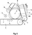
- Figure 6 shows in an overview an ideal contour 200 of the wound roll 3 (solid line) and a first state of deviation 201 of the circumference of the wound roll (dashed line).
- the first state of deviation 201 is characterized by diameter increases / contour changes of the wound roll 3 outwardly into the monitoring areas A, B, C.
- a second state of deviation 202 is indicated by the dot-dashed line in Figure 6 , in which the circumference in each of the monitoring areas A, B, C, is too small.
- the method according to the present invention comprises, in particular, the steps:
- Corresponding target states (desired states) of the wound roll 3 being formed are known for particular stages of the winding process. These target states are preferably stored in a database, in particular in a memory 45.
- the actual states captured by the image-capturing device 30 are compared to corresponding target states, i.e., with the chronologically corresponding target states, e.g., a state in which the roll has a particular number X of windings. If deviations exceeding a particular tolerance are detected, then selected operating parameters of the apparatus 1 are influenced by means of a correcting unit 50.
- the selection of the respective operating parameter and the direction and the amount of modification of this operating parameter are corrected accordingly.
- an incorrectly set operating parameter can be clearly attributed to a defect characteristic. It is, however, also possible that multiple incorrect operating parameters can lead to a particular defect characteristic and these are then modified according to the findings in the knowledge database in the memory 45.
- the occurrence of known deviations of actual states from target states of the wound roll 3 can be detected and automatically corrected through modified operation of the apparatus 1. A correcting intervention by a machine operator is thus no longer necessary.
- the method according to the present invention has the particular advantage that the monitoring can be continuous or in short intervals so that immediate action is possible when a winding error (deviation too large) occurs and a winding reject can be avoided.
Landscapes
- Controlling Rewinding, Feeding, Winding, Or Abnormalities Of Webs (AREA)
- Engineering & Computer Science (AREA)
- Mechanical Engineering (AREA)
- Registering, Tensioning, Guiding Webs, And Rollers Therefor (AREA)
- Controlling Sheets Or Webs (AREA)
- Separation, Sorting, Adjustment, Or Bending Of Sheets To Be Conveyed (AREA)
- Winding Of Webs (AREA)
Claims (12)
- Procédé pour enrouler une bande de non-tissés de laine minérale (4) en un rouleau enroulé au moyen d'un appareil (1) comprenant des dispositifs fixes et mobiles incluant au moins :- un espace d'enroulement (2) pour recevoir un rouleau au moins partiellement enroulé (3) ayant un centre d'enroulement (Z) ;- des moyens pour transporter et/ou manipuler la bande de non-tissés de laine minérale (4) avant et/ou pendant l'enroulement ;caractérisé en ce qu'il comprend les étapes suivantes :a) faire fonctionner l'appareil (1) ;b) surveiller la bande de non-tissés de laine minérale (4) et/ou le rouleau enroulé résultant (3) au moyen d'au moins un dispositif de capture d'image (30) pour obtenir au moins un état réel de la bande de non-tissés de laine minérale (4) et/ou du rouleau enroulé (3) ;c) comparer l'état réel au moins à un état cible et correspondant à l'état réel, et déterminer au moins un écart de l'état réel par rapport à l'état cible correspondant ;d) si l'écart dépasse/dépasse vers le bas au moins une valeur limite prédéterminée, effectuer une correction d'au moins un paramètre de fonctionnement de l'appareil (1), le paramètre de fonctionnement étant au moins un facteur de contribution à l'écart.
- Le procédé selon la revendication 1, caractérisé en ce que l'au moins un état cible est stocké dans une base de données.
- Le procédé selon la revendication 1 ou 2, caractérisé en ce que la surveillance est effectuée de telle sorte qu'une circonférence (U) du rouleau enroulé (3) autour de son centre d'enroulement (Z) est détectée et/ouune forme de bande de la bande de non-tissés de laine minérale (4) est détectée dans le sens de la hauteur (16) avant d'atteindre le rouleau enroulé (3) et/ouune position du centre d'enroulement (Z) du rouleau enroulé (3) par rapport à la circonférence (U) du rouleau enroulé (3) est détectée.
- Le procédé selon l'une des revendications 1 à 3, caractérisé en ce que
la surveillance de la bande de non-tissés de laine minérale (4) et du rouleau enroulé (3) est effectuée individuellement ou cumulativement aux emplacements énumérés ci-dessous :- zone de surveillance (A) entre un premier moyen de transport (5) et un deuxième moyen de transport (8) ;- zone de surveillance (B) entre le deuxième moyen de transport (8) et un bras d'enroulement (19) d'un rouleau d'enroulement (18) ;- zone de surveillance (C) entre le rouleau d'enroulement (18) et le premier moyen de transport (5) ;- dans lequel les zones de surveillance (A, B, C) sont disposées à proximité de la circonférence actuelle (U) du rouleau enroulé (3). - Le procédé selon l'une des revendications précédentes, caractérisé en ce que la comparaison de l'état réel à l'état cible est effectuée en comparant les contours circonférentiels réels aux contours circonférentiels cibles du rouleau enroulé (3) et/ou de la bande de non-tissés en laine minérale (4).
- Le procédé selon l'une des revendications précédentes, caractérisé en ce que pour réduire les écarts déterminés, au moins un paramètre de fonctionnement, choisi parmi les paramètres de fonctionnement suivants, est corrigé :- hauteur (h) d'une ligne de contact de pré-pressage (17) d'un dispositif de pré-pressage (11) ;- distance D d'un bord d'extrémité libre (14) de la barre de pré-pressage (13) par rapport à la circonférence (U) du rouleau enroulé (3), le bord d'extrémité libre étant orienté dans le sens de transport ;- une vitesse de transport (v1) du premier moyen de transport (5) ;- une vitesse de transport (v2) du deuxième moyen de transport (8) ;- une force de contact F du rouleau d'enroulement (18) sur la circonférence (U) du rouleau enroulé (3) ;- un angle (α) entre un premier sens de transport du premier moyen de transport (5) et un second sens de transport du second moyen de transport (8) ;- une courbe de mouvement du bras d'enroulement (19) ;- une vitesse circonférentielle du rouleau d'enroulement (18) ;- une troisième vitesse de transport (v3) du dispositif de pré-pressage (11).
- Le procédé selon l'une des revendications précédentes, caractérisé en ce que la surveillance, la comparaison et/ou la correction sont effectuées en continu.
- Le procédé selon l'une des revendications précédentes, caractérisé en ce qu' une valeur moyenne de plusieurs états réels chronologiquement successifs est utilisée pour la comparaison.
- Le procédé selon l'une des revendications précédentes, caractérisé en ce que
le ou les paramètres de fonctionnement sont corrigés si :a) en cas de surveillance continue de l'état réel, un écart est détecté sur une période minimale et l'écart dépasse/dépasse une valeur limite pendant ladite période minimale, oub) en cas de surveillance intermittente, une valeur moyenne de plusieurs écarts dépasse/dépasse la valeur limite correspondante. - Le procédé selon l'une des revendications précédentes, caractérisé en ce que la surveillance de la bande de non-tissés de laine minérale (4) et/ou du rouleau enroulé (3) qui en résulte au moyen d'au moins un dispositif de capture d'images (30) comprend en outre la surveillance d'au moins une partie de l'appareil (1), en particulier d'au moins une partie des dispositifs mobiles.
- Appareil pour la mise en œuvre du procédé selon l'une des revendications 1 à 10, comprenant des dispositifs fixes et mobiles incluant au moins :- un espace d'enroulement pour recevoir un rouleau au moins partiellement enroulé (3) ayant un centre d'enroulement (Z) ;- des moyens pour transporter et/ou manipuler la bande de non-tissés de laine minérale (4) avant et/ou pendant l'enroulement ;ledit appareil comprenant en outre- au moins un dispositif de capture d'image (30) pour surveiller la bande de non-tissés de laine minérale (4) et/ou le rouleau enroulé (3) ;- au moins une unité d'analyse (40) comparant les informations d'image des états réels aux états cibles stockés et déterminant les écarts ;- au moins une unité de correction (50) pour corriger au moins un paramètre de fonctionnement de l'appareil (1) ;- des moyens pour régler le au moins un paramètre de fonctionnement corrigé sur l'appareil (1).
- L'appareil selon la revendication 11, caractérisé par
une mémoire (45) prévue au moins pour stocker des données d'image concernant les états cibles de l'appareil (1) ou du rouleau enroulé (3).
Applications Claiming Priority (2)
| Application Number | Priority Date | Filing Date | Title |
|---|---|---|---|
| DE102019120122.5A DE102019120122A1 (de) | 2019-07-25 | 2019-07-25 | Verfahren zum Aufwickeln einer Materialbahn, insbesondere aus einem kompressiblen, zusammenpressbaren Material sowie Vorrichtung zum Durchführen des Verfahrens |
| PCT/EP2020/070524 WO2021013823A1 (fr) | 2019-07-25 | 2020-07-21 | Procédé d'enroulement d'une bande de matériau, en particulier d'un matériau compressible et appareil pour effectuer le procédé |
Publications (3)
| Publication Number | Publication Date |
|---|---|
| EP4003889A1 EP4003889A1 (fr) | 2022-06-01 |
| EP4003889B1 true EP4003889B1 (fr) | 2025-04-16 |
| EP4003889C0 EP4003889C0 (fr) | 2025-04-16 |
Family
ID=71738153
Family Applications (1)
| Application Number | Title | Priority Date | Filing Date |
|---|---|---|---|
| EP20743682.5A Active EP4003889B1 (fr) | 2019-07-25 | 2020-07-21 | Procédé d'enroulement d'une bande de non-tissés de laine minérale et appareil pour effectuer le procédé |
Country Status (9)
| Country | Link |
|---|---|
| US (1) | US12180021B2 (fr) |
| EP (1) | EP4003889B1 (fr) |
| JP (1) | JP7322278B2 (fr) |
| KR (1) | KR102632207B1 (fr) |
| AU (1) | AU2020318693B2 (fr) |
| DE (1) | DE102019120122A1 (fr) |
| ES (1) | ES3023236T3 (fr) |
| PL (1) | PL4003889T3 (fr) |
| WO (1) | WO2021013823A1 (fr) |
Families Citing this family (1)
| Publication number | Priority date | Publication date | Assignee | Title |
|---|---|---|---|---|
| CN121225053A (zh) * | 2025-12-01 | 2025-12-30 | 上海为隆节能环保技术有限公司 | 高线盘条打包机的垫片定位机构及垫片结构 |
Family Cites Families (19)
| Publication number | Priority date | Publication date | Assignee | Title |
|---|---|---|---|---|
| FR2553744B1 (fr) * | 1983-10-21 | 1986-03-28 | Saint Gobain Isover | Enrouleuse a compression asservie |
| ATE251586T1 (de) | 1996-07-16 | 2003-10-15 | Owens Corning Fiberglass Corp | Verfahren zur schmierung einer aufwickelvorrichtung |
| US5944273A (en) | 1997-07-03 | 1999-08-31 | Kimberly-Clark Worldwide, Inc. | Parent roll for tissue paper |
| ES2157651T3 (es) * | 1998-04-07 | 2001-08-16 | Techint Spa | Aparato mejorado para enrollar materiales fibrosos compresibles. |
| JP2000105104A (ja) | 1998-09-29 | 2000-04-11 | Nippon Paper Industries Co Ltd | 巻取り紙の偏芯検査装置 |
| DE19904167C1 (de) * | 1999-02-03 | 2000-10-26 | Rockwool Mineralwolle | Verfahren und Vorrichtung zur Herstellung einer Dämmstoffbahn |
| EP1497211A1 (fr) * | 2002-03-08 | 2005-01-19 | Metso Paper Karlstad AB | Installation et procede d'enroulement d'une bande de papier et dispositif de commande de la charge de contact |
| DE10218509A1 (de) | 2002-04-25 | 2003-11-06 | Voith Paper Patent Gmbh | Verfahren zur Herstellung einer Tissuebahn |
| FI118727B (fi) | 2004-06-30 | 2008-02-29 | Metso Paper Inc | Menetelmä rullaimessa ja rullain |
| JP4786939B2 (ja) | 2005-05-27 | 2011-10-05 | マスプロ電工株式会社 | 妨害排除能力試験装置 |
| DE102008038316A1 (de) | 2008-08-19 | 2010-03-25 | Fraunhofer-Gesellschaft zur Förderung der angewandten Forschung e.V. | Vorrichtung und Verfahren zum Bestimmen eines Abstandsmaßes an aufgewickelten Materialien |
| PL2206656T3 (pl) | 2009-01-13 | 2011-05-31 | Ursa Insulation Sa | Paczka dla produktów w postaci wełny mineralnej, moduły dla utworzenia takiej paczki i sposób wytwarzania takiej paczki |
| FI122537B (fi) * | 2009-11-05 | 2012-03-15 | Metso Paper Inc | Menetelmä ja laitteisto rainamaisen materiaalin pituusleikkauksen ohjaamiseksi |
| IT1401881B1 (it) * | 2010-09-28 | 2013-08-28 | Perini Fabio Spa | Macchina ribobinatrice e metodo per la produzione di rotoli di materiale nastriforme |
| JP5991258B2 (ja) | 2013-04-22 | 2016-09-14 | 東芝三菱電機産業システム株式会社 | ツードラムワインダ |
| DK178007B1 (en) | 2013-08-16 | 2015-03-02 | Inwatec Aps | Apparatus and method for rolling a carpet or a rug |
| DE102014005347A1 (de) * | 2014-04-11 | 2015-10-15 | Texmag Gmbh Vertriebsgesellschaft | Verfahren und Vorrichtung zur lnspektion und zur Konfektionierung einer laufenden Warenbahn |
| DE102015112142A1 (de) * | 2015-07-24 | 2017-01-26 | Saint-Gobain Isover G+H Ag | Verfahren zum Vorbereiten einer Dämmstoffbahn für den Transport und Vorrichtung zum Durchführen des Verfahrens |
| IT201800006607A1 (it) * | 2018-06-25 | 2019-12-25 | Ribobinatrice per la produzione di logs di materiale cartaceo. |
-
2019
- 2019-07-25 DE DE102019120122.5A patent/DE102019120122A1/de active Pending
-
2020
- 2020-07-21 EP EP20743682.5A patent/EP4003889B1/fr active Active
- 2020-07-21 PL PL20743682.5T patent/PL4003889T3/pl unknown
- 2020-07-21 US US17/626,671 patent/US12180021B2/en active Active
- 2020-07-21 ES ES20743682T patent/ES3023236T3/es active Active
- 2020-07-21 AU AU2020318693A patent/AU2020318693B2/en active Active
- 2020-07-21 JP JP2022503913A patent/JP7322278B2/ja active Active
- 2020-07-21 KR KR1020227005122A patent/KR102632207B1/ko active Active
- 2020-07-21 WO PCT/EP2020/070524 patent/WO2021013823A1/fr not_active Ceased
Also Published As
| Publication number | Publication date |
|---|---|
| WO2021013823A1 (fr) | 2021-01-28 |
| US20220411218A1 (en) | 2022-12-29 |
| AU2020318693B2 (en) | 2023-12-07 |
| US12180021B2 (en) | 2024-12-31 |
| AU2020318693A1 (en) | 2022-01-27 |
| DE102019120122A1 (de) | 2021-01-28 |
| EP4003889A1 (fr) | 2022-06-01 |
| ES3023236T3 (en) | 2025-05-30 |
| EP4003889C0 (fr) | 2025-04-16 |
| JP7322278B2 (ja) | 2023-08-07 |
| PL4003889T3 (pl) | 2025-09-01 |
| KR102632207B1 (ko) | 2024-02-01 |
| KR20220031935A (ko) | 2022-03-14 |
| JP2022541910A (ja) | 2022-09-28 |
Similar Documents
| Publication | Publication Date | Title |
|---|---|---|
| KR100574068B1 (ko) | 권취 장치 및 그 이용 방법과, 풀림 장치 | |
| EP1056666B1 (fr) | Procede et appareil de bobinage d'une bande | |
| EP3727042B1 (fr) | Procédé et unité de sertissage d'une bande de matière destinée à l'industrie du tabac | |
| JP2002532357A (ja) | 紙を巻取るための装置及び方法 | |
| WO1992019522A1 (fr) | Commande d'enroulement de bande | |
| CA2562122C (fr) | Procede et appareil de commande de bobinage | |
| US20030141404A1 (en) | Method for improving the operating reliability of a reel-up | |
| WO2009125298A2 (fr) | Appareil de transport de bande et procédé de commande de transport de bande | |
| EP1530044B1 (fr) | Sytème et procédé de mesure de la dureté de rouleaux | |
| EP2042654B1 (fr) | Calandre à bande et procédé de fonctionnement d'une calandre à bande | |
| US12180021B2 (en) | Method for winding up a web of material, in particular of a compressible material and an apparatus for carrying out the method | |
| EP1135317B1 (fr) | Procede et appareil pour commander la structure d'un bobinage | |
| JPH0367939B2 (fr) | ||
| RU2790208C1 (ru) | Способ наматывания полотна материала, в частности сжимаемого материала, и устройство для осуществления способа | |
| EP2319787B1 (fr) | Procédé et appareil pour contrôler le découpage longitudinal d'un matériau en bande | |
| JP2020093875A (ja) | フィルム巻取装置 | |
| CN223644337U (zh) | 复卷设备 | |
| JPH11217755A (ja) | ホージャリー編機へ伸縮性のある弾性糸を供給する送糸装置 | |
| JP2002362793A (ja) | ウェブ巻取装置及びウェブ巻取方法 | |
| JP2025116629A (ja) | シート巻取装置及びシート巻取方法 | |
| WO2024023856A1 (fr) | Unité de perforation pour matériaux de type bande | |
| KR100747237B1 (ko) | 슬리팅 코일 불량 상태 감지 자동화 장치 및 이를 통한조정 방법 | |
| CN121672250A (zh) | 一种分切机 | |
| JPH1077145A (ja) | シート材の検査方法および装置 | |
| JP2002362794A (ja) | ウェブ巻取装置及びウェブ巻取装置のニップ圧制御方法 |
Legal Events
| Date | Code | Title | Description |
|---|---|---|---|
| STAA | Information on the status of an ep patent application or granted ep patent |
Free format text: STATUS: UNKNOWN |
|
| STAA | Information on the status of an ep patent application or granted ep patent |
Free format text: STATUS: THE INTERNATIONAL PUBLICATION HAS BEEN MADE |
|
| PUAI | Public reference made under article 153(3) epc to a published international application that has entered the european phase |
Free format text: ORIGINAL CODE: 0009012 |
|
| STAA | Information on the status of an ep patent application or granted ep patent |
Free format text: STATUS: REQUEST FOR EXAMINATION WAS MADE |
|
| 17P | Request for examination filed |
Effective date: 20220112 |
|
| AK | Designated contracting states |
Kind code of ref document: A1 Designated state(s): AL AT BE BG CH CY CZ DE DK EE ES FI FR GB GR HR HU IE IS IT LI LT LU LV MC MK MT NL NO PL PT RO RS SE SI SK SM TR |
|
| DAV | Request for validation of the european patent (deleted) | ||
| DAX | Request for extension of the european patent (deleted) | ||
| P01 | Opt-out of the competence of the unified patent court (upc) registered |
Effective date: 20230421 |
|
| STAA | Information on the status of an ep patent application or granted ep patent |
Free format text: STATUS: EXAMINATION IS IN PROGRESS |
|
| 17Q | First examination report despatched |
Effective date: 20231124 |
|
| GRAP | Despatch of communication of intention to grant a patent |
Free format text: ORIGINAL CODE: EPIDOSNIGR1 |
|
| RIC1 | Information provided on ipc code assigned before grant |
Ipc: B65B 57/14 20060101ALI20241104BHEP Ipc: B65B 63/02 20060101ALI20241104BHEP Ipc: B65H 18/26 20060101ALI20241104BHEP Ipc: B65H 18/22 20060101AFI20241104BHEP |
|
| STAA | Information on the status of an ep patent application or granted ep patent |
Free format text: STATUS: GRANT OF PATENT IS INTENDED |
|
| INTG | Intention to grant announced |
Effective date: 20241212 |
|
| GRAS | Grant fee paid |
Free format text: ORIGINAL CODE: EPIDOSNIGR3 |
|
| GRAA | (expected) grant |
Free format text: ORIGINAL CODE: 0009210 |
|
| STAA | Information on the status of an ep patent application or granted ep patent |
Free format text: STATUS: THE PATENT HAS BEEN GRANTED |
|
| P04 | Withdrawal of opt-out of the competence of the unified patent court (upc) registered |
Free format text: CASE NUMBER: APP_6503/2025 Effective date: 20250207 |
|
| AK | Designated contracting states |
Kind code of ref document: B1 Designated state(s): AL AT BE BG CH CY CZ DE DK EE ES FI FR GB GR HR HU IE IS IT LI LT LU LV MC MK MT NL NO PL PT RO RS SE SI SK SM TR |
|
| REG | Reference to a national code |
Ref country code: GB Ref legal event code: FG4D |
|
| REG | Reference to a national code |
Ref country code: CH Ref legal event code: EP |
|
| REG | Reference to a national code |
Ref country code: IE Ref legal event code: FG4D |
|
| U01 | Request for unitary effect filed |
Effective date: 20250422 |
|
| U07 | Unitary effect registered |
Designated state(s): AT BE BG DE DK EE FI FR IT LT LU LV MT NL PT RO SE SI Effective date: 20250425 |
|
| REG | Reference to a national code |
Ref country code: ES Ref legal event code: FG2A Ref document number: 3023236 Country of ref document: ES Kind code of ref document: T3 Effective date: 20250530 |
|
| PGFP | Annual fee paid to national office [announced via postgrant information from national office to epo] |
Ref country code: GB Payment date: 20250529 Year of fee payment: 6 |
|
| U20 | Renewal fee for the european patent with unitary effect paid |
Year of fee payment: 6 Effective date: 20250606 |
|
| PGFP | Annual fee paid to national office [announced via postgrant information from national office to epo] |
Ref country code: ES Payment date: 20250807 Year of fee payment: 6 |
|
| PG25 | Lapsed in a contracting state [announced via postgrant information from national office to epo] |
Ref country code: NO Free format text: LAPSE BECAUSE OF FAILURE TO SUBMIT A TRANSLATION OF THE DESCRIPTION OR TO PAY THE FEE WITHIN THE PRESCRIBED TIME-LIMIT Effective date: 20250716 Ref country code: GR Free format text: LAPSE BECAUSE OF FAILURE TO SUBMIT A TRANSLATION OF THE DESCRIPTION OR TO PAY THE FEE WITHIN THE PRESCRIBED TIME-LIMIT Effective date: 20250717 |
|
| PGFP | Annual fee paid to national office [announced via postgrant information from national office to epo] |
Ref country code: TR Payment date: 20250709 Year of fee payment: 6 |
|
| PG25 | Lapsed in a contracting state [announced via postgrant information from national office to epo] |
Ref country code: HR Free format text: LAPSE BECAUSE OF FAILURE TO SUBMIT A TRANSLATION OF THE DESCRIPTION OR TO PAY THE FEE WITHIN THE PRESCRIBED TIME-LIMIT Effective date: 20250416 |
|
| PG25 | Lapsed in a contracting state [announced via postgrant information from national office to epo] |
Ref country code: RS Free format text: LAPSE BECAUSE OF FAILURE TO SUBMIT A TRANSLATION OF THE DESCRIPTION OR TO PAY THE FEE WITHIN THE PRESCRIBED TIME-LIMIT Effective date: 20250716 |
|
| PG25 | Lapsed in a contracting state [announced via postgrant information from national office to epo] |
Ref country code: IS Free format text: LAPSE BECAUSE OF FAILURE TO SUBMIT A TRANSLATION OF THE DESCRIPTION OR TO PAY THE FEE WITHIN THE PRESCRIBED TIME-LIMIT Effective date: 20250816 |
|
| PG25 | Lapsed in a contracting state [announced via postgrant information from national office to epo] |
Ref country code: SM Free format text: LAPSE BECAUSE OF FAILURE TO SUBMIT A TRANSLATION OF THE DESCRIPTION OR TO PAY THE FEE WITHIN THE PRESCRIBED TIME-LIMIT Effective date: 20250416 |
|
| PG25 | Lapsed in a contracting state [announced via postgrant information from national office to epo] |
Ref country code: CZ Free format text: LAPSE BECAUSE OF FAILURE TO SUBMIT A TRANSLATION OF THE DESCRIPTION OR TO PAY THE FEE WITHIN THE PRESCRIBED TIME-LIMIT Effective date: 20250416 |
|
| PGFP | Annual fee paid to national office [announced via postgrant information from national office to epo] |
Ref country code: PL Payment date: 20250608 Year of fee payment: 6 |
|
| PG25 | Lapsed in a contracting state [announced via postgrant information from national office to epo] |
Ref country code: SK Free format text: LAPSE BECAUSE OF FAILURE TO SUBMIT A TRANSLATION OF THE DESCRIPTION OR TO PAY THE FEE WITHIN THE PRESCRIBED TIME-LIMIT Effective date: 20250416 |
|
| PLBE | No opposition filed within time limit |
Free format text: ORIGINAL CODE: 0009261 |
|
| STAA | Information on the status of an ep patent application or granted ep patent |
Free format text: STATUS: NO OPPOSITION FILED WITHIN TIME LIMIT |
|
| REG | Reference to a national code |
Ref country code: CH Ref legal event code: H13 Free format text: ST27 STATUS EVENT CODE: U-0-0-H10-H13 (AS PROVIDED BY THE NATIONAL OFFICE) Effective date: 20260224 |
|
| REG | Reference to a national code |
Ref country code: CH Ref legal event code: L10 Free format text: ST27 STATUS EVENT CODE: U-0-0-L10-L00 (AS PROVIDED BY THE NATIONAL OFFICE) Effective date: 20260225 |
|
| 26N | No opposition filed |
Effective date: 20260119 |
|
| PG25 | Lapsed in a contracting state [announced via postgrant information from national office to epo] |
Ref country code: CH Free format text: LAPSE BECAUSE OF NON-PAYMENT OF DUE FEES Effective date: 20250731 |