EP4003899B1 - Procédé de production d'un système de cartouche - Google Patents
Procédé de production d'un système de cartouche Download PDFInfo
- Publication number
- EP4003899B1 EP4003899B1 EP20747368.7A EP20747368A EP4003899B1 EP 4003899 B1 EP4003899 B1 EP 4003899B1 EP 20747368 A EP20747368 A EP 20747368A EP 4003899 B1 EP4003899 B1 EP 4003899B1
- Authority
- EP
- European Patent Office
- Prior art keywords
- cartridge
- sealing element
- beverage
- sealing
- reservoir
- Prior art date
- Legal status (The legal status is an assumption and is not a legal conclusion. Google has not performed a legal analysis and makes no representation as to the accuracy of the status listed.)
- Active
Links
Images



Classifications
-
- A—HUMAN NECESSITIES
- A23—FOODS OR FOODSTUFFS; TREATMENT THEREOF, NOT COVERED BY OTHER CLASSES
- A23L—FOODS, FOODSTUFFS OR NON-ALCOHOLIC BEVERAGES, NOT OTHERWISE PROVIDED FOR; PREPARATION OR TREATMENT THEREOF
- A23L2/00—Non-alcoholic beverages; Dry compositions or concentrates therefor; Preparation or treatment thereof
- A23L2/52—Adding ingredients
- A23L2/54—Mixing with gases
-
- A—HUMAN NECESSITIES
- A47—FURNITURE; DOMESTIC ARTICLES OR APPLIANCES; COFFEE MILLS; SPICE MILLS; SUCTION CLEANERS IN GENERAL
- A47J—KITCHEN EQUIPMENT; COFFEE MILLS; SPICE MILLS; APPARATUS FOR MAKING BEVERAGES
- A47J31/00—Apparatus for making beverages
- A47J31/40—Beverage-making apparatus with dispensing means for adding a measured quantity of ingredients, e.g. coffee, water, sugar, cocoa, milk, tea
- A47J31/41—Beverage-making apparatus with dispensing means for adding a measured quantity of ingredients, e.g. coffee, water, sugar, cocoa, milk, tea of liquid ingredients
-
- B—PERFORMING OPERATIONS; TRANSPORTING
- B21—MECHANICAL METAL-WORKING WITHOUT ESSENTIALLY REMOVING MATERIAL; PUNCHING METAL
- B21D—WORKING OR PROCESSING OF SHEET METAL OR METAL TUBES, RODS OR PROFILES WITHOUT ESSENTIALLY REMOVING MATERIAL; PUNCHING METAL
- B21D22/00—Shaping without cutting, by stamping, spinning, or deep-drawing
- B21D22/20—Deep-drawing
- B21D22/28—Deep-drawing of cylindrical articles using consecutive dies
-
- B—PERFORMING OPERATIONS; TRANSPORTING
- B65—CONVEYING; PACKING; STORING; HANDLING THIN OR FILAMENTARY MATERIAL
- B65B—MACHINES, APPARATUS OR DEVICES FOR, OR METHODS OF, PACKAGING ARTICLES OR MATERIALS; UNPACKING
- B65B29/00—Packaging of materials presenting special problems
- B65B29/02—Packaging of substances, e.g. tea, which are intended to be infused in the package
- B65B29/022—Packaging of substances, e.g. tea, which are intended to be infused in the package packaging infusion material into capsules
-
- B—PERFORMING OPERATIONS; TRANSPORTING
- B65—CONVEYING; PACKING; STORING; HANDLING THIN OR FILAMENTARY MATERIAL
- B65B—MACHINES, APPARATUS OR DEVICES FOR, OR METHODS OF, PACKAGING ARTICLES OR MATERIALS; UNPACKING
- B65B61/00—Auxiliary devices, not otherwise provided for, for operating on sheets, blanks, webs, binding material, containers or packages
- B65B61/18—Auxiliary devices, not otherwise provided for, for operating on sheets, blanks, webs, binding material, containers or packages for making package-opening or unpacking elements
-
- B—PERFORMING OPERATIONS; TRANSPORTING
- B67—OPENING, CLOSING OR CLEANING BOTTLES, JARS OR SIMILAR CONTAINERS; LIQUID HANDLING
- B67D—DISPENSING, DELIVERING OR TRANSFERRING LIQUIDS, NOT OTHERWISE PROVIDED FOR
- B67D1/00—Apparatus or devices for dispensing beverages on draught
- B67D1/0042—Details of specific parts of the dispensers
- B67D1/0078—Ingredient cartridges
- B67D1/0079—Ingredient cartridges having their own dispensing means
-
- B—PERFORMING OPERATIONS; TRANSPORTING
- B67—OPENING, CLOSING OR CLEANING BOTTLES, JARS OR SIMILAR CONTAINERS; LIQUID HANDLING
- B67D—DISPENSING, DELIVERING OR TRANSFERRING LIQUIDS, NOT OTHERWISE PROVIDED FOR
- B67D1/00—Apparatus or devices for dispensing beverages on draught
- B67D1/08—Details
- B67D1/0801—Details of beverage containers, e.g. casks, kegs
- B67D1/0804—Shape or materials
-
- B—PERFORMING OPERATIONS; TRANSPORTING
- B67—OPENING, CLOSING OR CLEANING BOTTLES, JARS OR SIMILAR CONTAINERS; LIQUID HANDLING
- B67D—DISPENSING, DELIVERING OR TRANSFERRING LIQUIDS, NOT OTHERWISE PROVIDED FOR
- B67D1/00—Apparatus or devices for dispensing beverages on draught
- B67D1/08—Details
- B67D1/0801—Details of beverage containers, e.g. casks, kegs
- B67D2001/0811—Details of beverage containers, e.g. casks, kegs provided with coded information
-
- B—PERFORMING OPERATIONS; TRANSPORTING
- B67—OPENING, CLOSING OR CLEANING BOTTLES, JARS OR SIMILAR CONTAINERS; LIQUID HANDLING
- B67D—DISPENSING, DELIVERING OR TRANSFERRING LIQUIDS, NOT OTHERWISE PROVIDED FOR
- B67D1/00—Apparatus or devices for dispensing beverages on draught
- B67D1/08—Details
- B67D1/0801—Details of beverage containers, e.g. casks, kegs
- B67D2001/0812—Bottles, cartridges or similar containers
- B67D2001/0814—Bottles, cartridges or similar containers for upside down use
Definitions
- the present invention relates to a method for producing a cartridge system for producing a beverage, wherein the cartridge system can be used in a beverage preparation machine, has a cartridge which comprises a reservoir filled with a beverage substance, and has a cartridge receptacle connected to the cartridge, wherein the cartridge receptacle has a mixing chamber which can be brought into fluid connection with the reservoir and a fluid supply opening into the mixing chamber, wherein the cartridge is made at least partially of aluminum.
- the beverage substance is mixed with a predetermined amount of liquid, in particular cold and carbonated water, and then poured into a drinking vessel.
- a predetermined amount of liquid in particular cold and carbonated water
- mixed drinks in particular can be produced much more easily, quickly and with less effort.
- the user can choose from a variety of different cartridges, allowing them to produce different beverages according to their preferences.
- a major challenge with such systems is to minimize the dispensing time, the time required from the time the user starts the beverage preparation process to the time required to produce the finished beverage, in order to increase user convenience.
- Another challenge is to provide sufficient beverage substance and sufficient carbonation for a flavorful beverage, especially during this dispensing time, which must be minimized.
- the subject of the present invention is a method for producing a cartridge system, wherein in a first method step, an aluminum sheet is provided, wherein in a second method step, the main body is at least partially produced from the sheet by punching and deep drawing or extrusion, wherein in a third method step, a sealing element is attached to the main body, and wherein in a fourth method step, the main body is connected to the cartridge receptacle.
- the method according to the invention enables the rapid and cost-effective production of a comparatively stable cartridge, which enables shorter draw-off times and higher carbon dioxide contents.
- the cartridge holder could be manufactured by injection molding plastic.
- the part of the cartridge system that is not subject to high pressure due to the introduction of compressed air is manufactured from plastic using a cost-effective manufacturing process, thus keeping overall manufacturing costs low.
- a piercing mandrel is produced and introduced into a mandrel guide of the cartridge holder.
- the sealing element in the form of the sealing body is punched and/or cut out from an aluminum sheet and/or from a sealing film, preferably a plastic film, an aluminum foil or a multi-layer film made of plastic and/or aluminum.
- a sealing film preferably a plastic film, an aluminum foil or a multi-layer film made of plastic and/or aluminum.
- the sheet in particular is then deep-drawn in the second method step such that the sealing body of the sealing element formed from the aluminum sheet preferably has a wall thickness between 0.09 and 0.5 millimeters, preferably between 0.1 and 0.3 millimeters, particularly preferably between 0.15 and 0.25 millimeters and most preferably of substantially 0.2 millimeters, in particular with an error tolerance of a maximum of 15%.
- the partial area in the sealing body is partially punched to form the pre-punched portion.
- the pre-punching thus defines the subsequent through-opening, which in the initial state is closed by the partial area still connected to the remaining sealing body and is only opened by the piercing mandrel immediately before or during beverage production.
- the sealing element is formed around an edge of the cartridge wall.
- This forming can be carried out both in the variant in which the sealing element comprises the sealing body made of rigid or semi-rigid aluminum, and in the variant in which the sealing element consists exclusively of the sealing film.
- the sealing element is crimped, glued, sealed, and/or welded to the edge of the cartridge wall.
- the sealing element comprises the sealing body made of rigid or semi-rigid aluminum
- the sealing body is, in particular, crimped to the cartridge wall.
- the sealing element consists exclusively of the sealing film
- the sealing film is, in particular, glued, sealed, and/or welded to the cartridge wall.
- a fastening region of the sealing element is arranged between the edge of the cartridge wall and a part of the cartridge receptacle and is in particular clamped, welded, and/or glued in.
- the fastening region is thus additionally secured by the connecting and counter-connecting means.
- a through-opening is created in the sealing element, in particular is drilled into the sealing element, and wherein the through-opening is closed in a later further intermediate step with a sealing film, wherein the sealing film is preferably glued, welded and/or sealed to the sealing element.
- the sealing element a rigid or semi-rigid aluminum sealing body.
- This sealing body is provided with the through-hole, which is then sealed in a subsequent intermediate step by the perforable sealing film.
- This sealing film can be arranged and attached to the sealing body on the mixing chamber side or arranged and attached to the sealing body on the reservoir side.
- a connecting means in particular a locking bead, a locking bead or an undercut
- a counter-connecting means in particular a locking bead, a locking bead or an undercut, is then preferably produced on the cartridge receptacle.
- a fastening region of the sealing element is then arranged between the connecting means and the counter-connecting means and in particular to be clamped, welded and/or glued in during the fourth method step.
- the cup-shaped main body is preferably produced entirely by deep drawing or extrusion in the second process step.
- the main body is preferably cup-shaped with a cylindrical cartridge wall that is closed on one side by a cartridge base, wherein the cartridge wall and the cartridge base are in particular formed as a single piece. It is conceivable for the cartridge wall and the cartridge base to consist of one piece and in particular both of aluminum, by deep-drawing the main body from an aluminum sheet.
- the main body can also be produced only partially by deep drawing or extrusion by bending an aluminum sheet into a cylindrical tube and then gluing, welding and/or pressing the butt sides of the aluminum sheet bent into the tube together to create a main body with a longitudinal seam, wherein the cartridge base is then additionally formed as a separate lid body by deep drawing or extrusion of another aluminum sheet.
- This cartridge base designed as a separate cap body, can then be slipped over the end of the tubular cartridge wall facing away from the cartridge receptacle, where it can be glued, welded, and/or pressed to the cartridge wall all the way around.
- the cap body is crimped onto the tubular cartridge wall to form the cartridge base.
- a cartridge system for producing a beverage in a beverage preparation machine in which the production of a flavorful beverage is achieved with a minimal dispensing time.
- the cartridge system has the advantage that it is made of aluminum rather than plastic.
- the cartridge is therefore significantly more stable and can withstand higher internal pressure.
- the liquid beverage substance in particular, can be enclosed in the reservoir under higher pressure without damaging or deforming the cartridge. It is therefore possible to store liquid beverage substances with a higher carbon dioxide content in the reservoir without the risk of the reservoir bursting due to the carbon dioxide in the event of shocks, for example, during transport or storage of the cartridge system.
- the higher carbon dioxide content in turn, has a positive effect on both the taste of the beverage being produced and the cartridge's best-before date.
- a further advantage of the eCartridge system is that the reservoir can be emptied at higher pressure during the beverage production process. This significantly reduces the dispensing time without impairing the taste of the beverage being produced.
- the cartridge has a main body made of aluminum, which in its typical wall area preferably has a wall thickness of between 0.01 and 0.5 millimeters, preferably between 0.01 and 0.2 millimeters, more preferably between 0.03 and 0.1 millimeters, and most preferably substantially 0.05 millimeters, in particular with a maximum error tolerance of 15%.
- the cartridge is then preferably designed such that it can withstand an internal pressure of up to 10 bar, more preferably up to 8 bar, and most preferably up to 6 bar without bursting (at a temperature of 20°C and an external pressure of 1 bar).
- the reservoir preferably has a volume of between 10 and 500 milliliters, more preferably between 30 and 90 milliliters, and most preferably substantially 60 milliliters.
- the cartridge system in particular comprises a liquid beverage substance, which is preferably carbonated.
- the liquid beverage substance comprises a beverage concentrate, in particular a syrup.
- the cartridge may comprise a cup-shaped main body.
- the cup-shaped main body is preferably produced by deep drawing or extrusion, which advantageously enables comparatively cost-effective and rapid production.
- the cartridge is thus necessarily hermetically sealed on one side, which ensures a particularly A stable cartridge design is realized.
- the main body is cup-shaped with a cylindrical cartridge wall that is closed on one side by a cartridge base, wherein the cartridge wall and the cartridge base are particularly formed in one piece. It is conceivable that the cartridge wall and the cartridge base consist of one piece, in particular both of aluminum, by deep-drawing the main body from an aluminum sheet.
- the main body can also be formed by bending an aluminum sheet into a cylindrical tube and then gluing, welding and/or pressing the butt ends of the aluminum sheet bent into the tube together to create a main body with a longitudinal seam.
- the cartridge base is formed as a separate lid body, in particular by deep drawing or extrusion of another aluminum sheet. This cartridge base, designed as a separate lid body, can then be slipped over the end of the cartridge wall bent into the tube that faces away from the cartridge receptacle and there glued, welded and/or pressed all the way to the cartridge wall.
- the lid body is crimped onto the tubular cartridge wall to form the cartridge base.
- the main body in its initial position, is sealed by a sealing element on the side opposite the cartridge base.
- This sealing element advantageously ensures that the beverage substance remains within the reservoir before the beverage production process begins, where it is hermetically sealed for a long shelf life and consistent aroma.
- the sealing element comprises a particularly rigid or semi-rigid sealing body with a pre-punch. In the area of the pre-punch, a portion of the sealing body is partially punched. This means that the portion is not completely punched out of the sealing element, but only partially punched out, so that in the initial state of the cartridge, it remains integrally connected to the remaining sealing element in its corner areas. Thus, the reservoir 7 remains hermetically sealed in the initial state.
- the sealing element is in particular the sealing body made of aluminum.
- the size of the punch preferably corresponds essentially to the through-opening in the sealing element to be created later by the piercing mandrel.
- a predetermined breaking point relative to the remaining sealing body is formed by the partial punching, which Upon contact of the partial region with a piercing mandrel of the beverage preparation machine (see below), the partial region at least partially tears open to expose the through-opening. Because the partial region is punched out of the sealing body, it has essentially the same size or diameter as the through-opening, in which the piercing mandrel is also arranged during beverage production. This advantageously prevents the detached partial region from passing through the through-opening 18' into the mixing chamber 8.
- the sealing element has a particularly rigid or semi-rigid sealing body with a through-opening.
- the sealing element is made in particular of aluminum and attached to the main body. It is conceivable that the sealing body is crimped, glued, clamped, welded and/or pressed onto the main body.
- the through-opening is formed either centrally or offset from the center in the sealing body.
- the sealing body is thus disc-shaped and/or annular.
- the sealing body is also cup-shaped, with the circumferential part protruding from the cup base running parallel to the cartridge wall and being pressed or crimped onto this part of the cartridge wall.
- the sealing element comprises a sealing film which closes the through-opening in the initial position of the cartridge system, wherein the sealing film is preferably a plastic film, an aluminum foil or a multi-layer film made of plastic and/or aluminum.
- the sealing film is easily perforated by a piercing mandrel (see below) of the cartridge receptacle in order to transfer the beverage substance from the reservoir into the mixing chamber of the cartridge receptacle as quickly as possible.
- a circumferential edge of the sealing film is attached to the sealing element, in particular glued, sealed and/or welded.
- the sealing element comprises a sealing film, preferably a plastic film, an aluminum foil, or a multilayer film made of plastic and/or aluminum, which is particularly attached to the edge of the cartridge wall.
- the sealing element does not have an additional sealing body; rather, the opening of the main body is hermetically sealed directly and particularly exclusively by the sealing film, which is directly attached to the edge of the cartridge wall.
- a circumferential peripheral attachment region of the sealing element is preferably crimped, glued, sealed, and/or welded to the cartridge wall, and particularly to the edge of the cartridge wall.
- the fastening area extends at least partially parallel to the cartridge wall on the inside or outside.
- the sealing film is also cup-shaped. It is conceivable that the sealing film is also deep-drawn into this shape.
- the sealing body of the sealing element could also be designed as a type of crimp cap. It is conceivable that the cartridge wall comprises a circumferential edge around which the sealing body is crimped for attachment to the cartridge. Alternatively, the sealing element could be screwed onto the end of the cartridge. For this purpose, a fastening area of the cartridge is provided in particular with an external thread onto which the sealing body is screwed. For this purpose, the sealing body in particular has an internal thread complementary to the external thread.
- the screw connection is preferably designed in such a way that only screwing on and subsequent locking is permitted, so that the locking prevents subsequent unscrewing.
- the edge of the cartridge wall has a particularly circumferential connecting means, in particular a locking bead, a locking bead, or an undercut, for connecting the cartridge to the sealing element and/or the cartridge receptacle.
- the sealing element and/or the cartridge receptacle has a counter-connecting means, in particular a further locking bead, a locking bead, or an undercut, which is complementary to the connecting means and is connected to the connecting means in a form-fitting, force-fitting, and/or material-fitting manner. This preferably makes it possible to achieve a stable and cost-effective connection between the cartridge and the cartridge receptacle and/or between the cartridge and the sealing element.
- the fastening area is arranged at least partially between the connecting means and the counter-connecting means and in particular is clamped, welded and/or glued in.
- the sealing element in particular the edge of the sealing body or the edge of the sealing film, is additionally fixed between the connecting means and the counter-connecting means, i.e. from both sides, during the beverage production process.
- a comparatively high overpressure can thus be generated within the reservoir without the risk of the sealing element becoming detached from the cartridge wall.
- the fastening area is located on the inside of the cartridge wall, so that the edge of the cartridge wall is arranged between the fastening area and the cartridge receptacle.
- the connecting means is arranged between the fastening means and the counter-connecting means.
- the preferably circumferential connecting means and/or counter-connecting means can also be designed as a locking bead, locking bead, undercut or the like. It is particularly preferred that both the fastening region of the sealing body and the edge region of the sealing film are arranged between the connecting means and the counter-connecting means.
- the cartridge wall or the sealing element comprises a circumferential edge around which the wall of the cartridge receptacle is crimped.
- the cartridge receptacle could be screwed onto the end of the cartridge or onto the sealing element.
- a fastening area of the cartridge or the sealing element is provided with an external thread, onto which the cartridge receptacle is screwed.
- the cartridge receptacle has an internal thread complementary to the external thread.
- the screw connection is preferably designed in such a way that only screwing on and subsequent locking is possible, so that the locking mechanism prevents subsequent unscrewing.
- the reservoir is not flushed with the fluid, but rather the beverage substance and the fluid enter the mixing chamber of the cartridge holder separately from one another.
- the fluid is fed directly into the mixing chamber, while the beverage substance is transferred to the mixing chamber independently of the fluid.
- a displaceably mounted piercing mandrel is arranged within the mandrel guide, wherein the piercing mandrel is displaceable between a retracted position, in which the piercing mandrel is spaced from the sealing element and in particular the sealing film (or the partial area), and an extended position, in which the piercing mandrel pierces the sealing element and in particular the sealing film (or partially or completely tears off the partial area from the sealing element) and projects into the reservoir.
- the piercing mandrel In the initial state of the cartridge system, the piercing mandrel is therefore in the retracted position, so that the reservoir is hermetically sealed by the sealing element and in particular the sealing film, and can be moved from the retracted position to the extended position to open the sealing element of the cartridge.
- the sealing element In the extended position, the sealing element is perforated by the piercing mandrel or a pre-punched area is torn open, so that the beverage substance passes through, in particular, at least one side channel on the piercing mandrel past the sealing element into the mixing chamber.
- the design of the mixing chamber in the cartridge holder which can be reversibly inserted into the beverage preparation machine, advantageously ensures that the mixing chamber is part of the replaceable cartridge system. In this way, contamination of the beverage preparation machine by the beverage substance is effectively prevented because only parts of the replaceable disposable or reusable cartridge system come into contact with the beverage substance.
- the cartridge system and in particular the cartridge receptacle have at least one support structure that supports the sealing film in the direction of the cartridge receptacle and in particular in the direction of the mixing cartridge.
- the support structure comprises, in particular, a columnar, bridge-shaped, lattice-shaped, or cylindrical structure that extends from the bottom of the mixing chamber toward the reservoir and on which the sealing film partially rests.
- the piercing mandrel prefferably, to comprise a cylindrical or frustoconical base part and a piercing part extending in the direction of the reservoir, wherein the piercing part is designed in the form of an obliquely cut truncated cone.
- the piercing part is further designed such that an oblique cut surface of the obliquely cut truncated cone faces substantially towards the reservoir, wherein the oval circumference of the cut surface at least partially represents a cutting edge for perforating the sealing element.
- the cutting surface created by an oblique cut through the truncated cone cuts the sealing element easily and with sufficiently little effort, and on the other hand, does not separate any chips or loose pieces from the sealing element, which would otherwise unintentionally contaminate the beverage.
- the sealing element perforation is advantageously designed such that on the side of the piercing mandrel on which the cut edge protruding maximally in the direction of the reservoir is formed, the material of the sealing element is severed with a smooth cut, while in the region of the cut surface of the piercing part, the cut-off material of the sealing element is still connected to the remaining sealing element and is preferably rolled up or folded together.
- the piercing mandrel preferably comprises an intermediate part arranged between the base part and the piercing part, which is truncated cone-shaped, with a circumferential shoulder formed between the base part and the intermediate part and a circumferential edge formed between the piercing part and the intermediate part.
- a stable piercing mandrel is thus formed.
- the design of the edge has the advantage that the side channels, if they extend over the edge, have an enlarged inlet on the reservoir side, thus facilitating the transfer of the beverage substance towards the mixing chamber.
- the step serves to strike against a stop of the mandrel guide when the piercing mandrel is in the extended position, so that the extension movement of the piercing mandrel towards the cartridge is limited.
- the cartridge holder has a plurality of side channels, each side channel extending parallel to the piercing mandrel in the area of the piercing part and in the area of the intermediate part.
- the side channels are in particular each in the form of a recess cut into the outer surface of the
- the side channels are preferably formed as a groove open on one side in the piercing mandrel.
- the side channels are preferably formed at least partially in a peripheral region of the piercing mandrel that is rearward of the cutting surface.
- the cross-section of the side channels and/or the number of side channels is adapted to the viscosity of the beverage substance, so that the side channels control or limit the flow of the beverage substance toward the mixing chamber.
- the side channels control or limit the flow of the beverage substance toward the mixing chamber.
- multiple side channels or side channels with a larger cross-section are used, while for lower viscosity, fewer side channels or side channels with a smaller cross-section are provided.
- the piercing mandrel has an anti-twist feature in the form of a web projecting radially from the base part. This advantageously prevents twisting of the piercing mandrel when moving from the retracted position to the extended position. Furthermore, it is ensured that the side channels are arranged on the side of the piercing mandrel that faces away from the beverage outlet of the mixing chamber and, in particular, faces the fluid supply. This achieves improved mixing of the beverage substance and the fluid within the mixing chamber.
- the piercing mandrel prefferably has an integrated compressed air line, which serves as the cartridge discharge device, wherein the compressed air line extends along the piercing mandrel, in particular from a first end of the piercing mandrel to a second end of the piercing mandrel.
- three functions are thus integrated into the piercing mandrel: 1.
- the piercing mandrel comprises the piercing part for perforating the sealing element and thus opening the cartridge.
- the piercing mandrel comprises the side channels for transferring the beverage substance into the mixing chamber.
- the piercing mandrel comprises the integrated compressed air line for blowing compressed air into the reservoir, thereby forcing the beverage substance under pressure into the mixing chamber.
- a compressed air connection for connection to a compressed air source is formed at the second end, and a compressed air outlet for blowing compressed air into the reservoir is formed at the first end.
- the cartridge unloading device integrated into the cartridge receptacle therefore initially comprises only a compressed air line through which compressed air can be introduced from outside into the reservoir.
- the cartridge receptacle is designed such that the compressed air forces the beverage substance from the reservoir into the mixing chamber.
- the compressed air is provided, in particular, by the beverage preparation machine. It is conceivable that a compressed air source is coupled directly to the compressed air connection as soon as the cartridge system is inserted into the beverage preparation machine.
- the beverage substance can therefore only move from the reservoir towards the mixing chamber.
- the compressed air outlet is designed as an opening in the cut surface. This has the advantage that the air flowing into the reservoir is blown into the piercing mandrel on a side facing away from the side channels, thus unhindering the discharge of the beverage substance into the mixing chamber. This preferably creates a vortex in the reservoir, which promotes almost complete emptying of the reservoir.
- the compressed air connection is designed, in particular, as an opening in the base part, with the base part being arranged in the cartridge receptacle in such a way that the compressed air connection is accessible from outside the cartridge receptacle. This facilitates the connection of the compressed air line to the compressed air source.
- the mandrel guide comprises a guide part with an internal guide channel for receiving the piercing mandrel, wherein the guide channel of the guide part is substantially cylindrical or frustoconical in shape and wherein a circumferential stop is formed on an end of the guide part facing the cartridge, which limit the movement of the piercing mandrel in the direction of the reservoir, wherein the stop in particular comprises a region with a reduced diameter.
- this achieves reliable guidance of the piercing mandrel during the movement from the retracted position to the extended position.
- a groove corresponding to the web serves as an anti-twist device, preventing unintentional twisting of the piercing mandrel.
- the guide part is preferably arranged in the mixing chamber and protrudes from a bottom of the mixing chamber toward the cartridge.
- the piercing mandrel could be designed as a plastic part, particularly as an injection-molded plastic part. This would enable cost-effective production. However, it would also be conceivable to design the piercing mandrel as a metal part.
- the piercing mandrel is designed in such a way that, when the cartridge system is inserted into the beverage preparation machine, it can be moved from the retracted position to the extended position by a trigger element of the beverage preparation machine.
- the mixing chamber has a beverage outlet through which the beverage formed from a mixture of the beverage substance with the fluid is dispensed, wherein the cartridge system is preferably designed such that the beverage can be introduced from the beverage outlet directly into a portable container.
- the cartridge system is preferably designed such that the beverage can be introduced from the beverage outlet directly into a portable container.
- neither the beverage substance nor the produced beverage comes into contact with any part of the beverage preparation machine, thus preventing almost any (re-)contamination of the beverage preparation machine.
- the fluid is fed separately to the mixing chamber.
- the fluid is introduced into the mixing chamber under pressure.
- the fluid is provided in particular by the beverage preparation machine. It is conceivable that a fluid source is coupled directly to a corresponding fluid connection of the cartridge holder as soon as the cartridge system is inserted into the beverage preparation machine.
- the fluid connection is in fluid communication with the mixing chamber via a fluid line.
- This has the advantage of effectively preventing backcontamination toward the beverage preparation machine because the fluid connection is pressurized, particularly immediately upon insertion of the cartridge system, thus preventing beverage substance from migrating toward the fluid line and, in particular, toward the fluid source of the beverage preparation machine.
- the beverage substance and the beverage can thus only move from the mixing chamber toward the beverage outlet.
- the fluid comprises, in particular, water, preferably pressurized, chilled, and/or carbonated drinking water.
- the mixing chamber is provided with mixing structures.
- the mixing structures advantageously ensure improved mixing of the beverage substance and the fluid.
- the mixing structures are designed in particular such that the fluid flowing into the mixing chamber is swirled.
- the mixing structure comprises one or more mixing webs which are arranged in the region of the fluid supply at the bottom of the mixing chamber and extend essentially perpendicular to the inflow direction of the fluid. The mixing webs thus act as barriers for the fluid, whereby the fluid is swirled and better mixing with the beverage substance is achieved.
- the fluid supply is fed with fluid cooled by a cooling unit, whereby the cooling unit is part of the beverage preparation machine or a separate refrigerator operatively connected to the beverage preparation machine.
- a cooling unit is part of the beverage preparation machine or a separate refrigerator operatively connected to the beverage preparation machine.
- Integrating the system into an existing refrigerator has the advantage that the refrigerator's existing cooling unit can be easily and efficiently used for the beverage preparation machine.
- side-by-side refrigerators often referred to as American refrigerators
- the beverage preparation machine is a retrofit kit for such a refrigerator.
- the cooling unit preferably comprises a compressor cooling unit, an absorption cooling unit, or a thermoelectric cooler.
- the fluid supply is fed with fluid which is carbonated by a carbonator.
- the carbonator is part of the beverage preparation machine and wherein the carbonator has a receptacle for a CO2 cartridge and a feed device for adding CO2 from the CO2 cartridge to the fluid.
- the system can therefore also be used to produce carbonated soft drinks.
- the carbonator it would also be conceivable for the carbonator to have an external CO2 connection.
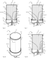
- Figures 1a , 1b and 1c are a perspective view, a schematic sectional view and the general operating principle of a cartridge system.
- the illustrated cartridge system 1 is intended to be inserted into a beverage preparation machine (not shown) to prepare a beverage 70.
- the cartridge system 1 comprises a cartridge 2 filled with a beverage substance 7 and a cartridge receptacle 10 connected to the cartridge 2.
- a corresponding beverage 70 is produced with the aid of the beverage substance 7 and an additional water source, hereinafter referred to as fluid source 41.
- the cartridge 2 is preferably filled with a pre-portioned amount of beverage substance 7, which is necessary to produce a specific drinking portion, for example, a drinking glass full of the desired beverage 70.
- the beverage substance 7 is, in particular, a liquid and carbonated beverage concentrate in the form of syrup.
- a plurality of different cartridge systems 1 are available, the cartridges 2 or reservoirs 6 of which are filled with different beverage substances 7 for producing various beverages 70. If the user of the system 1 wishes to drink a specific beverage 70, they merely need to select the cartridge system 1 from the plurality of different cartridge systems 1 that contains the corresponding beverage substance 7 for producing the desired beverage 70, insert it into a holding unit of the beverage preparation machine, and start the beverage preparation process on the beverage preparation machine, for example by pressing a start button, touching a touch-sensitive display, through gesture or voice control, or by means of a suitable application on a mobile phone. It is also conceivable for the beverage preparation process to start automatically when the insertion of a new cartridge system 1 into the holding unit is detected.
- the desired beverage 70 is then automatically produced, directed into a drinking vessel, and thus made available to the user.
- the used cartridge system 1 is then removed and disposed of.
- the beverage preparation machine 3 is now ready to be filled with any new cartridge system 1 to produce another beverage 70.
- the beverage substance 7 preferably comprises liquid pre-mix ingredients for soft drinks, such as caffeinated, carbonated, fruit and/or sugar-containing lemonades and juices, beer (mixed) drinks or other alcoholic or non-alcoholic (mixed) drinks.
- soft drinks such as caffeinated, carbonated, fruit and/or sugar-containing lemonades and juices, beer (mixed) drinks or other alcoholic or non-alcoholic (mixed) drinks.
- the cartridge system 1 comprises a cartridge 2 in the form of a cylindrical container.
- the container is hollow and thus contains a reservoir 6 for the beverage substance 7.
- the cartridge 2 is formed by a cup-shaped main body 2' made of aluminum.
- Cup-shaped here means that the main body 2' has a cartridge base 2′′′ (shown above in the drawing) and a cartridge wall 2" extending perpendicularly from the cartridge base 2′′′ in the direction of the cartridge receptacle 10.
- the cartridge wall 2" is cylindrical and circumferential, while the cartridge base 2′′′ in this example has a circular and disc-shaped design.
- the main body 2' is deep-drawn and punched from an aluminum sheet (either deep-drawn first and then punched or vice versa), so that the cartridge base 2′′′ and the cartridge wall 2" are integrally connected to one another.
- the sealing element 18 exclusively comprises a particularly thin sealing film 18", which closes the reservoir 6 so that the beverage substance 7 is sealed aroma-tight.
- the outer peripheral edge region of the sealing element 18 is attached peripherally to the edge 2 ⁇ of the cartridge wall 2".
- the sealing element 18 is glued, sealed, or welded to the edge 2 ⁇ of the cartridge wall 2".
- the sealing film 18" comprises, in particular, a plastic film, an aluminum foil, or a multilayer film made of plastic and/or aluminum.
- the cartridge 2 is fixedly or reversibly connected to the cartridge receptacle 10.
- the cartridge receptacle 10 is connected to the cartridge receptacle 10 in particular after the production (deep drawing and punching or extrusion and punching) of the main body 2', after filling the cartridge 2 with the beverage substance 7 and after closing the reservoir 6 by applying the sealing element 18.
- the cartridge wall 2" optionally has circumferential connecting means 20, in particular in the form a circumferential locking bead.
- the cartridge receptacle 10 optionally has complementary mating connecting means 21 to the connecting means 20, in particular in the form of a circumferential locking bead, which engages the locking bead when the cartridge 2 is connected to the cartridge receptacle 10. It is conceivable that the cartridge wall 2" and the cartridge receptacle 10 are additionally glued, welded, and/or pressed together.
- the main body 2' preferably has a wall thickness of between 0.01 and 0.5 millimeters in its typical wall region, preferably between 0.01 and 0.2 millimeters, particularly preferably between 0.03 and 0.1 millimeters, and most preferably substantially 0.05 millimeters, in particular with a maximum error tolerance of 15%.
- the cartridge is then preferably designed such that it can withstand an internal pressure of up to 10 bar, particularly preferably up to 8 bar, and most preferably up to 6 bar without bursting (at a temperature of 20°C and an external pressure of 1 bar).
- the cartridge 2 is then preferably designed such that it can withstand an internal pressure of up to 10 bar, particularly preferably up to 8 bar, and most preferably up to 6 bar without bursting (at a temperature of 20°C and an external pressure of 1 bar).
- the reservoir 6 preferably comprises a volume of between 10 and 500 milliliters, particularly preferably between 30 and 90 milliliters and most preferably substantially 60 milliliters.
- the cartridge receptacle 10 has a mixing chamber 8, which is in fluid communication with the reservoir 6 during the beverage production process, so that with the aid of a cartridge unloading device of the cartridge receptacle 10, the beverage substance 7 can be at least partially transferred from the reservoir 6 into the mixing chamber 8.
- the cartridge unloading device comprises a compressed air line 40.
- One end of the compressed air line 40 is connected to a compressed air connection 42, which can be connected to a compressed air source of the beverage preparation machine in order to introduce compressed air into the compressed air line 40, while the other end opens into a compressed air outlet, which is open towards the reservoir 6 and introduces compressed air into the reservoir 6.
- the introduction of the compressed air causes the beverage substance 7 to be pressed into the mixing chamber 8.
- the fluid supply has a quick coupling with which the fluid supply 12 can be connected to the fluid source of the beverage preparation machine.
- the quick coupling can, for example, be designed such that when the cartridge system 1 is inserted into the holding unit, a fluid connection is automatically established between the fluid source and the mixing chamber 8 via the fluid supply 12.
- fluid in particular chilled and carbonated drinking water
- beverage substance 7 flows from the reservoir 6 into the mixing chamber 8, as described above. By mixing the beverage substance 7 with the fluid in the mixing chamber 8, the beverage 70 is formed, which then leaves the mixing chamber 8 through a beverage outlet 11.
- the cartridge holder 10 has the beverage outlet 11, through which the beverage 70 produced within the mixing chamber 8 exits the mixing chamber 8 and is directed, in particular, directly into the drinking vessel (not shown), i.e., without any parts of the beverage preparation machine coming into contact with the beverage 70. This prevents backcontamination of the beverage preparation machine.
- the drinking vessel is arranged, in particular, directly below the beverage outlet 11.
- the cartridge system 1 is removed from the holding unit so that the beverage production machine can be equipped with a new and unused cartridge system 1.
- the cartridge holder 10 can optionally be reused by separating it from the used cartridge 2 by loosening the snap-in connection and clipping it onto a new cartridge 2.
- the cartridge receptacle 10 has a mandrel guide 80 in which a piercing mandrel 73 is displaceably mounted.
- the sealing element 18 is moved by transferring the displaceable piercing mandrel 73 between a retracted position, in which the piercing mandrel 73 is spaced from the sealing element 18 (cf. Figure 1b ), and an extended position in which the piercing mandrel 73 pierces the sealing element 18 (cf. Figure 1c ) and extends into the reservoir 6, perforated.
- the outer wall of the piercing spike 73 is provided with a plurality of side channels 71 for guiding the beverage substance 7 from the reservoir 6 toward the mixing chamber 8 when the sealing element 18 is pierced.
- the side channels 71 are designed as grooves running parallel to one another and open on one side. After the sealing element 18 is pierced, the side channels 71 come into fluid communication with the reservoir 6, so that the beverage substance 7 can flow around the edges of the pierced sealing element 18 in the direction of the mixing chamber 8.
- the compressed air line 40 which functions as a cartridge unloading device, is also integrated into the piercing mandrel 73.
- the compressed air line 40 opens into the reservoir 6 at the end of the piercing mandrel 73 when the piercing mandrel 73 is in the extended position.
- the compressed air connection 42 is formed on a side of the piercing mandrel 73, in particular facing away from the reservoir 6. This connection is thus accessible from outside the cartridge holder 10 and can be connected to the compressed air source of the beverage preparation machine.
- the piercing mandrel 73 is moved from the retracted position to the extended position during or after insertion of the cartridge system 10 into the beverage preparation machine or after starting the beverage production process, preferably by a fixed trigger element of the holding unit against which the piercing mandrel 73 is pressed.
- the piercing mandrel 71 is preferably formed as a plastic part and particularly preferably as a plastic injection-molded part.
- both the fluid source and the compressed air source are directly coupled to the fluid supply 12 or the compressed air connection 42 as soon as the cartridge system 1 is inserted into the beverage preparation machine or a beverage production process is started, and in particular before the sealing element 18 is pierced.
- the fluid supply 12 and the cartridge unloading device are under overpressure, in particular immediately upon insertion of the cartridge system 1, thus preventing beverage substance 7 from migrating towards the fluid source or compressed air source.
- the beverage substance 7 can thus move from the reservoir 6 only in the direction of the mixing chamber 8 (see Figure 1c ) as soon as the sealing element 18 is opened.
- the cartridge receptacle 10 comprises a base structure 10' with a cup-shaped configuration.
- the open side of this cup-shaped configuration points toward the cartridge 2 and at least partially accommodates the cartridge 2, in particular the edge 2'' of the cartridge wall 2".
- the base structure 10' On an opposite bottom side 10", the base structure 10' has the beverage outlet opening 11 and the outwardly open mandrel guide 80.
- the fluid supply 12 is formed on a side wall 10' of the base structure 10'.
- the base structure 10' is designed in particular as a plastic part and particularly preferably as a plastic injection-molded part.
- Figure 2 is a schematic cross-sectional view of another cartridge system.
- the second embodiment is similar to that shown in Figures 1a, 1b and 1c illustrated and explained first embodiment, wherein, in contrast, the cartridge holder 10 additionally has support structures 22 which support the sealing film 18".
- the support structures 22 comprise column- and support-like elements which extend from the bottom side 10" of the base structure 10' (in particular within the mixing chamber 8) in the direction of the reservoir 6 to such an extent that the sealing film 18' can be supported or rested on the elements and is protected from unintentional tearing, in particular during transport and storage of the cartridge system 1.
- Figures 3a and 3b are a schematic sectional view and the general operating principle of another cartridge system.
- the third embodiment is similar to the one shown in Figures 1a, 1b and 1c illustrated and explained first embodiment, wherein, in contrast, the sealing element 18 does not consist exclusively of a sealing film 18", but comprises a rigid or semi-rigid sealing body 18′′′ which is made of aluminum.
- the sealing body 18′′′ has a through-opening 18', which in the initial state of the cartridge system 1 is closed by a sealing foil 18" (see Figure 3a ).
- the through-opening 18' is arranged in such a way that the piercing mandrel 73, when moved from the retracted position to the extended position, projects through the through-opening 18' and pierces the sealing foil 18" (see Figure 3b ).
- the piercing mandrel 73 does not come into contact with the sealing body 18′′′.
- the sealing body 18′′′ can therefore be designed to be very stable.
- the sealing film 18' in turn comprises a plastic film, an aluminum foil, or a multilayer film made of plastic and/or aluminum, the peripheral edge of which is preferably glued, sealed, and/or welded to the sealing body 18′′′.
- the sealing film 18' is arranged and/or attached to the sealing body 18′′′, in particular on the outside of the sealing body 18′′′, i.e., on the side facing the mixing chamber 8.
- the sealing body 18′′′ is preferably crimped with its edge region to the edge 2 ⁇ of the cartridge wall 2′′ in order to fasten the sealing body 18′′′ to the main body 2′. It is conceivable that the cartridge wall 2′′ has a circumferential web at the edge 2 ⁇ as a connecting means 20, around which the sealing body 18′′′ is crimped.
- the sealing body 18′′′ thus represents a type of crimp cap.
- the sealing body 18′′′ to be screwed to the cartridge wall 2", i.e. an internal thread of the sealing body 18′′′ engages with an external thread on the cartridge wall 2".
- the screw connection is preferably designed in such a way that only screwing on and subsequent locking is possible, so that the locking prevents subsequent unscrewing.
- the edge of the cartridge wall 2" has a particularly circumferential connecting means 20, in particular a locking bead, a locking bead or an undercut, for connecting the cartridge 2 to the sealing body 18′′′.
- the sealing body 18′′′ has a counter-connecting means 21 complementary to the connecting means 20, in particular a further locking bead, a locking bead or an undercut, which is connected to the connecting means 20 in a form-fitting, force-fitting and/or material-fitting manner.
- the sealing body 18′′′ preferably has a wall thickness of between 0.09 and 0.5 millimeters, preferably between 0.1 and 0.3 millimeters, particularly preferably between 0.15 and 0.25 millimeters and very particularly preferably substantially 0.2 millimeters, in particular with an error tolerance of a maximum of 15%, in its typical wall area.
- FIG 4 is a schematic sectional view of another cartridge system.
- the fourth embodiment is similar to that shown in Figures 1a, 1b and 1c illustrated and explained first embodiment, wherein, in contrast to the third embodiment, the sealing film 18" is not arranged on the outside of the sealing body 18′′′, but wherein the Sealing film 18" is arranged and in particular fastened on the inside of the sealing body 18′′′ facing the reservoir 6.
- the sealing film 18' in turn comprises a plastic film, an aluminum foil or a multi-layer film made of plastic and/or aluminum, the peripheral edge of which is preferably glued, sealed and/or welded to the inside of the sealing body 18′′′.
- FIG 5 is a schematic sectional view of another cartridge system.
- the fifth embodiment is similar to that shown in Figures 3a and 3b illustrated and explained third embodiment, wherein, in contrast to the third embodiment, the sealing body 18′′′ has a fastening area on its edge.
- This fastening area is angled by 90 degrees compared to the remaining area of the sealing body 18′′′ and thus extends parallel to the cartridge wall 2". There is therefore an overlap area between the fastening area and the edge 2 ⁇ of the cartridge wall 2".
- the sealing body 18′′′ is thus also cup-shaped.
- the fastening area has a slightly larger radius than the edge 2 ⁇ of the cartridge wall 2", so that the fastening area is at least partially arranged between the edge 2 ⁇ of the cartridge wall 2" and the edge of the cartridge receptacle 10.
- the fastening region is arranged in particular between the connecting means 20 and the counter-connecting means 21 and is additionally fastened there, in particular by gluing, clamping, pressing, welding or the like.
- the sealing body 18 ⁇ is formed into its cup-shaped configuration from the aluminum sheet, in particular by deep drawing or extrusion.
- the cartridge wall 2" and the cartridge receptacle 10 additionally have the connecting and counter-connecting means 20, 21.
- these connecting and counter-connecting means 20, 21 are not implemented.
- FIG 6 is a schematic sectional view of another cartridge system.
- the sixth embodiment is similar to that shown in Figure 5 illustrated and explained fourth Embodiment, wherein, in contrast to the fourth embodiment, the sealing body 18′′′ has a smaller radius than the cartridge wall 2".
- the fastening area is thus arranged on the inside of the cartridge wall 2", so that the edge 2 ⁇ of the cartridge wall 2" is arranged between the fastening area and the edge of the cartridge receptacle 10 and is fastened there, in particular by gluing, clamping, pressing, welding or the like.
- the cartridge wall 2" and the cartridge receptacle 10 additionally have the connecting and counter-connecting means 20, 21.
- these connecting and counter-connecting means 20, 21 are not implemented.
- Figure 7 is a schematic sectional view of another cartridge system.
- the sixth embodiment is similar to that shown in Figure 5 illustrated and explained fourth embodiment, wherein, in contrast to the fourth embodiment, the sealing film 18" extends to the fastening area.
- Figures 8a and 8b are a perspective view and a schematic sectional view of another cartridge system.
- the eighth embodiment is similar to that shown in Figures 1a, 1b and 1c illustrated and explained first embodiment, wherein the main body 2' is not produced by the deep-drawing process.
- the main body 2' therefore does not consist of a cartridge wall 2" and a cartridge base 2" that are integrally connected to one another.
- the main body 2' is formed by bending an aluminum sheet into a cylindrical tube. The butt sides of the sheet bent into the tube are then glued, welded, or pressed together, creating a longitudinal seam 23.
- the cartridge base 2′′′ is formed as a separate lid body 24, in particular by deep drawing or extrusion of another aluminum sheet.
- This cartridge base 2′′′, formed as a separate lid body 24, is then slipped over that end of the cartridge wall 2" bent into a tube, which faces away from the cartridge receptacle 10 and there is circumferentially connected to the cartridge wall 2". glued, welded and/or pressed.
- the lid body 24 is crimped onto the tubular cartridge wall 2" to form the cartridge base 2′′′.
- the subsequent manufacturing steps can optionally be carried out as in one of the other embodiments described above (first to seventh embodiments).
- Figures 9a and 9b are a schematic sectional view and a detailed view of the sealing element 18 of the further cartridge system.
- the ninth embodiment is similar to that shown in Figures 3a and 3b illustrated and explained third embodiment, wherein, in contrast, the sealing element 18 does not comprise a sealing film 18", but consists only of the sealing body 18′′′.
- the sealing body 18′′′ is again rigid or semi-rigid and is made of aluminum.
- the sealing body 18′′′ has a pre-punch 27, in which a partial area 19 of the sealing body 18′′′ is partially pre-punched out of the sealing body 18′′′.
- this partial area 19 is not completely punched out by the pre-punch 25, but only partially punched out, so that it remains integrally connected to the remaining sealing body 18′′′ in its corner areas and seals the reservoir 7 against the mixing chamber 8.
- This initial state (also referred to as the delivery state of the cartridge) is shown in Figure 9a illustrated.
- the sealing body 18′′′ Due to the pre-punch 25 of the sealing element 18 or sealing body 18′′′, the sealing body 18′′′ has a weakened or predetermined breaking point in the edge area of the partial area 19. If the piercing mandrel 73 now strikes the partial area 19 before or during beverage production and pushes it toward the reservoir 7, the connection between the partial area 19 and the remaining sealing body 19 tears or breaks at least partially, thereby forming the through-opening 18', particularly according to the size of the pre-punch 25.
- the partial area 19 is punched out of the sealing body 18′′′, it has essentially the same size or diameter as the through-opening 18', in which the piercing mandrel 73 is also arranged during beverage production. This advantageously prevents the detached partial area 19 from passing through the through-opening 18' into the mixing chamber 8.
Landscapes
- Engineering & Computer Science (AREA)
- Mechanical Engineering (AREA)
- Food Science & Technology (AREA)
- Health & Medical Sciences (AREA)
- Nutrition Science (AREA)
- Life Sciences & Earth Sciences (AREA)
- Chemical & Material Sciences (AREA)
- Polymers & Plastics (AREA)
- Apparatus For Making Beverages (AREA)
- Details Of Rigid Or Semi-Rigid Containers (AREA)
- Devices For Dispensing Beverages (AREA)
- Supplying Of Containers To The Packaging Station (AREA)
Claims (12)
- Procédé de fabrication d'un système de cartouche (1) pour la fabrication d'une boisson (70), le système de cartouche (1) pouvant être inséré dans une machine de préparation de boissons (3), une cartouche (2) qui comprend un réservoir (6) rempli d'une substance de boisson (7), et un logement de cartouche (10) relié à la cartouche (2), le logement de cartouche (10) présentant une chambre de mélange (8) pouvant être mise en communication fluidique avec le réservoir (6) et une amenée de fluide (12) débouchant dans la chambre de mélange (8), la cartouche (2) étant fabriquée au moins partiellement en aluminium, caractérisé en ce que dans une première étape de procédé, une tôle d'aluminium est préparée, dans une deuxième étape de procédé, le corps principal (2') étant produit au moins partiellement à partir de la tôle d'aluminium par estampage et emboutissage ou extrusion, dans une troisième étape de procédé, un élément d'étanchéité (18) étant fixé au corps principal (2') et dans une quatrième étape de procédé, le corps principal (2') étant relié au logement de cartouche (10).
- Procédé selon la revendication 1, dans lequel, dans une étape intermédiaire réalisée avant la quatrième étape de procédé, le logement de cartouche (10) est fabriqué par moulage par injection de matière plastique.
- Procédé selon l'une quelconque des revendications 1 ou 2, dans lequel, au cours d'une autre étape intermédiaire réalisée avant ou après la quatrième étape de procédé, un mandrin de perçage (73) est fabriqué et inséré dans un guide de mandrin (80) du logement de cartouche (10).
- Procédé selon l'une quelconque des revendications 1 à 3, dans lequel, dans une autre étape intermédiaire réalisée avant la troisième étape de procédé, l'élément d'étanchéité (18) est découpé à l'emporte-pièce et/ou découpé sous la forme d'un corps d'étanchéité (18''') dans une tôle d'aluminium et/ou dans une feuille d'étanchéité (18"), de préférence une feuille de matière plastique, une feuille d'aluminium ou une feuille multicouche de matière plastique et/ou d'aluminium.
- Procédé selon la revendication 4, dans lequel, dans une autre étape intermédiaire, la zone partielle (10) est partiellement découpée à l'emporte-pièce dans le corps d'étanchéité (18) pour former la pré-découpe (25).
- Procédé selon l'une quelconque des revendications 1 à 5, dans lequel, dans une autre étape intermédiaire réalisée avant ou pendant la troisième étape de procédé, l'élément d'étanchéité (18) est façonné autour d'un bord (2ʺʺ) de la paroi de la cartouche (2'').
- Procédé selon l'une quelconque des revendications 1 à 6, dans lequel, pendant la troisième étape de procédé, l'élément d'étanchéité (18) est serti, collé, scellé et/ou soudé sur le bord (2ʺʺ) de la paroi de la cartouche (2").
- Procédé selon l'une quelconque des revendications 1 à 7, dans lequel, pendant la quatrième étape de procédé, une zone de fixation de l'élément d'étanchéité (18) est agencée entre le bord (2ʺʺ) de la paroi de la cartouche (2'') et une partie du logement de cartouche (10) et est notamment serrée, soudée et/ou collée.
- Procédé selon l'une quelconque des revendications 1 à 8, dans lequel, dans une autre étape intermédiaire, une ouverture de passage (18') est produite dans l'élément d'étanchéité (18), notamment est percée dans l'élément d'étanchéité (18'), et dans lequel l'ouverture de passage (18') est fermée par une feuille d'étanchéité (18") dans une autre étape intermédiaire ultérieure, la feuille d'étanchéité (18") étant de préférence collée, soudée et/ou scellée sur l'élément d'étanchéité (18).
- Procédé selon l'une quelconque des revendications 1 à 9, dans lequel, dans une autre étape intermédiaire réalisée pendant ou après la deuxième étape de procédé, un moyen de liaison (20), notamment une moulure d'encliquetage, un bourrelet d'encliquetage ou une contre-dépouille, est produit dans la paroi de la cartouche (2"), notamment par mise en forme.
- Procédé selon l'une quelconque des revendications 1 à 10, dans lequel, avant la quatrième étape de procédé et notamment pendant le moulage par injection du logement de cartouche (10), un moyen de liaison complémentaire (21), (20), notamment une moulure d'encliquetage, un bourrelet d'encliquetage ou une contre-dépouille, est produit sur le logement de cartouche (10).
- Procédé selon l'une quelconque des revendications 1 à 11, dans lequel, pendant la quatrième étape de procédé, une zone de fixation de l'élément d'étanchéité (18) est agencée entre le moyen de liaison (20) et le moyen de liaison complémentaire (21) et est notamment serrée, soudée et/ou collée.
Applications Claiming Priority (3)
| Application Number | Priority Date | Filing Date | Title |
|---|---|---|---|
| DE102019211189 | 2019-07-26 | ||
| DE102019212708 | 2019-08-23 | ||
| PCT/EP2020/070927 WO2021018760A1 (fr) | 2019-07-26 | 2020-07-24 | Système de cartouche et procédé de production d'un système de cartouche |
Publications (3)
| Publication Number | Publication Date |
|---|---|
| EP4003899A1 EP4003899A1 (fr) | 2022-06-01 |
| EP4003899B1 true EP4003899B1 (fr) | 2025-04-30 |
| EP4003899C0 EP4003899C0 (fr) | 2025-04-30 |
Family
ID=71846375
Family Applications (1)
| Application Number | Title | Priority Date | Filing Date |
|---|---|---|---|
| EP20747368.7A Active EP4003899B1 (fr) | 2019-07-26 | 2020-07-24 | Procédé de production d'un système de cartouche |
Country Status (12)
| Country | Link |
|---|---|
| US (1) | US12077329B2 (fr) |
| EP (1) | EP4003899B1 (fr) |
| JP (1) | JP7610572B2 (fr) |
| KR (1) | KR20220038424A (fr) |
| CN (1) | CN114206172B (fr) |
| AU (1) | AU2020323227B2 (fr) |
| CA (1) | CA3148715A1 (fr) |
| ES (1) | ES3036160T3 (fr) |
| HU (1) | HUE072055T2 (fr) |
| IL (1) | IL289618B2 (fr) |
| PL (1) | PL4003899T3 (fr) |
| WO (1) | WO2021018760A1 (fr) |
Families Citing this family (27)
| Publication number | Priority date | Publication date | Assignee | Title |
|---|---|---|---|---|
| US12077329B2 (en) * | 2019-07-26 | 2024-09-03 | Freezio Ag | Cartridge system and method for producing a cartridge system |
| US12213617B2 (en) | 2022-05-13 | 2025-02-04 | Sharkninja Operating Llc | Flavored beverage carbonation process |
| US12096880B2 (en) | 2022-05-13 | 2024-09-24 | Sharkninja Operating Llc | Flavorant for beverage carbonation system |
| US11647860B1 (en) | 2022-05-13 | 2023-05-16 | Sharkninja Operating Llc | Flavored beverage carbonation system |
| US11751585B1 (en) | 2022-05-13 | 2023-09-12 | Sharkninja Operating Llc | Flavored beverage carbonation system |
| CA3253404A1 (fr) | 2022-05-13 | 2023-11-16 | Sharkninja Operating Llc | Agitateur pour système de carbonatation |
| US12005404B2 (en) | 2022-08-22 | 2024-06-11 | Sharkninja Operating Llc | Beverage carbonation system flow control |
| US12539500B2 (en) | 2022-08-31 | 2026-02-03 | Sharkninja Operating Llc | Additive containers |
| US11745996B1 (en) | 2022-11-17 | 2023-09-05 | Sharkninja Operating Llc | Ingredient containers for use with beverage dispensers |
| US11634314B1 (en) | 2022-11-17 | 2023-04-25 | Sharkninja Operating Llc | Dosing accuracy |
| US11738988B1 (en) | 2022-11-17 | 2023-08-29 | Sharkninja Operating Llc | Ingredient container valve control |
| US12084334B2 (en) | 2022-11-17 | 2024-09-10 | Sharkninja Operating Llc | Ingredient container |
| US12103840B2 (en) | 2022-11-17 | 2024-10-01 | Sharkninja Operating Llc | Ingredient container with sealing valve |
| JP2025541753A (ja) * | 2022-12-02 | 2025-12-23 | ザ キュムラス コーヒー カンパニー | 飲料を生成するためのシステム |
| USD1091308S1 (en) | 2022-12-23 | 2025-09-02 | Sharkninja Operating Llc | Ingredient container |
| USD1092208S1 (en) | 2022-12-23 | 2025-09-09 | Sharkninja Operating Llc | Cap of ingredient container |
| US12116257B1 (en) | 2023-03-22 | 2024-10-15 | Sharkninja Operating Llc | Adapter for beverage dispenser |
| US11925287B1 (en) | 2023-03-22 | 2024-03-12 | Sharkninja Operating Llc | Additive container with inlet tube |
| US11871867B1 (en) | 2023-03-22 | 2024-01-16 | Sharkninja Operating Llc | Additive container with bottom cover |
| US12005408B1 (en) | 2023-04-14 | 2024-06-11 | Sharkninja Operating Llc | Mixing funnel |
| EP4727685A1 (fr) | 2023-06-16 | 2026-04-22 | SharkNinja Operating LLC | Chambre de carbonatation |
| USD1113343S1 (en) | 2023-09-20 | 2026-02-17 | The Cumulus Coffee Company | Pod |
| USD1111812S1 (en) | 2023-09-20 | 2026-02-10 | The Cumulus Coffee Company | Pod |
| US12612199B2 (en) * | 2023-11-02 | 2026-04-28 | Ralph E. McMorris | Process for preparing a pre-mixed alcoholic beverage |
| USD1113444S1 (en) | 2024-05-14 | 2026-02-17 | The Cumulus Coffee Company | Pod |
| USD1113443S1 (en) | 2024-05-14 | 2026-02-17 | The Cumulus Coffee Company | Pod |
| USD1132072S1 (en) | 2024-05-31 | 2026-06-30 | Sharkninja Operating Llc | Beverage dispenser |
Citations (1)
| Publication number | Priority date | Publication date | Assignee | Title |
|---|---|---|---|---|
| WO2017121796A1 (fr) * | 2016-01-12 | 2017-07-20 | Freezio Ag | Distributeur à support de cartouche |
Family Cites Families (23)
| Publication number | Priority date | Publication date | Assignee | Title |
|---|---|---|---|---|
| CH605293A5 (fr) * | 1976-12-17 | 1978-09-29 | Nestle Sa | |
| US5615801A (en) | 1990-06-06 | 1997-04-01 | The Coca-Cola Company | Juice concentrate package for postmix dispenser |
| TW199884B (fr) * | 1991-05-08 | 1993-02-11 | Sociere Des Produits Nestle S A | |
| JP2000262405A (ja) * | 1999-03-18 | 2000-09-26 | Soc Prod Nestle Sa | 飲料抽出用密封カートリッジ |
| AU2002364775A1 (en) | 2001-11-30 | 2003-06-10 | Labatt Brewing Company Limited | Beverage dispensing system and device |
| CA2421128C (fr) * | 2002-03-14 | 2008-05-20 | 1693778 Ontario Limited | Cartouche et filtre a boissons |
| US6648025B2 (en) | 2002-04-16 | 2003-11-18 | Coors Worldwide Inc. | Beverage dispense |
| DE602004007478T2 (de) * | 2004-03-26 | 2008-04-10 | Illycaffe S.P.A. | Anordnung zur Zubereitung eines Getränkes aus einer in einer Kartusche enthaltenen Pulversubstanz |
| PL1774878T3 (pl) * | 2005-10-14 | 2008-06-30 | Nestec Sa | Sposób sporządzania napoju z kapsułki |
| EP2017221A1 (fr) * | 2007-07-19 | 2009-01-21 | Nestec, Ltd. | Dispositif de distribution de liquide |
| DE202010006556U1 (de) * | 2010-05-06 | 2010-08-05 | Mahlich, Gotthard | Brüh- oder Zubereitungskammer für ein Getränkezubereitungsgerät |
| DE202011001661U1 (de) * | 2011-01-19 | 2011-06-09 | Mahlich, Gotthard, 61476 | Brüh- oder Zubereitungskammer für ein Getränkezubereitungsgerät |
| EP2782485B1 (fr) | 2011-09-09 | 2018-10-24 | Fountain Master, LLC | Appareil de préparation de boissons |
| PL3154874T3 (pl) | 2014-06-12 | 2019-01-31 | K-Fee System Gmbh | Kapsułka porcjowa z kalandrowanym materiałem włóknistym |
| EP3193676A4 (fr) * | 2014-09-19 | 2018-09-05 | La Vit Technology LLC | Système à base de capsule permettant de préparer et de distribuer une boisson |
| US10111554B2 (en) * | 2015-03-20 | 2018-10-30 | Meltz, LLC | Systems for and methods of controlled liquid food or beverage product creation |
| US9487348B2 (en) * | 2015-03-20 | 2016-11-08 | Meltz, LLC | Systems for and methods of providing support for displaceable frozen contents in beverage and food receptacles |
| MX2017014637A (es) | 2015-05-15 | 2018-01-23 | Douwe Egberts Bv | Capsula, sistema para la preparacion de una bebida potable a partir de la capsula, y uso de la capsula en un dispositivo para la preparacion de bebidas. |
| EP3225684A1 (fr) * | 2016-03-30 | 2017-10-04 | Anheuser-Busch InBev S.A. | Procédé de préparation d'une boisson à partir d'un récipient en portions ou kit dans des parties de récipient en portions, ledit récipient en portions et ledit kit dans des pièces |
| JP7245180B2 (ja) | 2017-06-26 | 2023-03-23 | フレーツィオ アーゲー | 飲料製造装置 |
| EP3434159A1 (fr) * | 2017-07-28 | 2019-01-30 | Anthony Kay | Système d'étanchéité pour capsules de boisson et système d'extraction de boissons |
| CN111386060B (zh) * | 2017-11-27 | 2022-07-05 | 弗里奇奥股份公司 | 料筒容纳部、料筒系统、饮料制备机以及用于生产饮料的方法 |
| US12077329B2 (en) * | 2019-07-26 | 2024-09-03 | Freezio Ag | Cartridge system and method for producing a cartridge system |
-
2020
- 2020-07-24 US US17/628,648 patent/US12077329B2/en active Active
- 2020-07-24 CN CN202080053313.7A patent/CN114206172B/zh active Active
- 2020-07-24 JP JP2022504165A patent/JP7610572B2/ja active Active
- 2020-07-24 AU AU2020323227A patent/AU2020323227B2/en active Active
- 2020-07-24 KR KR1020227005758A patent/KR20220038424A/ko not_active Ceased
- 2020-07-24 WO PCT/EP2020/070927 patent/WO2021018760A1/fr not_active Ceased
- 2020-07-24 PL PL20747368.7T patent/PL4003899T3/pl unknown
- 2020-07-24 ES ES20747368T patent/ES3036160T3/es active Active
- 2020-07-24 EP EP20747368.7A patent/EP4003899B1/fr active Active
- 2020-07-24 HU HUE20747368A patent/HUE072055T2/hu unknown
- 2020-07-24 CA CA3148715A patent/CA3148715A1/fr active Pending
-
2022
- 2022-01-04 IL IL289618A patent/IL289618B2/en unknown
Patent Citations (1)
| Publication number | Priority date | Publication date | Assignee | Title |
|---|---|---|---|---|
| WO2017121796A1 (fr) * | 2016-01-12 | 2017-07-20 | Freezio Ag | Distributeur à support de cartouche |
Also Published As
| Publication number | Publication date |
|---|---|
| JP2022541923A (ja) | 2022-09-28 |
| US12077329B2 (en) | 2024-09-03 |
| HUE072055T2 (hu) | 2025-10-28 |
| PL4003899T3 (pl) | 2025-09-01 |
| BR112022001232A2 (pt) | 2022-03-15 |
| CN114206172A (zh) | 2022-03-18 |
| JP7610572B2 (ja) | 2025-01-08 |
| AU2020323227A1 (en) | 2022-03-03 |
| IL289618B1 (en) | 2023-04-01 |
| AU2020323227B2 (en) | 2025-03-20 |
| EP4003899A1 (fr) | 2022-06-01 |
| EP4003899C0 (fr) | 2025-04-30 |
| KR20220038424A (ko) | 2022-03-28 |
| WO2021018760A1 (fr) | 2021-02-04 |
| CN114206172B (zh) | 2024-07-23 |
| CA3148715A1 (fr) | 2021-02-04 |
| IL289618A (en) | 2022-03-01 |
| IL289618B2 (en) | 2023-08-01 |
| ES3036160T3 (en) | 2025-09-15 |
| US20220274725A1 (en) | 2022-09-01 |
Similar Documents
| Publication | Publication Date | Title |
|---|---|---|
| EP4003899A1 (fr) | Système de cartouche et procédé de production d'un système de cartouche | |
| EP4017828A1 (fr) | Système de cartouche et procédé de production d'un système de cartouche | |
| EP3402737B1 (fr) | Logement de cartouche, système de cartouche, machine de préparation de boissons et procédé de préparation d'une boisson | |
| EP4232399B1 (fr) | Système de cartouche, machine de préparation de boissons et procédé de production d'un système de cartouche | |
| EP4370466A1 (fr) | Système de cartouche muni d'une cartouche fermée par une valve | |
| EP4274452B1 (fr) | Dispositif de réception pour cartouche, système de cartouche, système de préparation de boissons et procédé de préparation d'une boisson | |
| WO2025099239A1 (fr) | Pointe de perforation, support de cartouche, système de préparation d'une boisson, procédé de préparation d'une boisson et utilisation d'une pointe de perforation |
Legal Events
| Date | Code | Title | Description |
|---|---|---|---|
| STAA | Information on the status of an ep patent application or granted ep patent |
Free format text: STATUS: UNKNOWN |
|
| STAA | Information on the status of an ep patent application or granted ep patent |
Free format text: STATUS: THE INTERNATIONAL PUBLICATION HAS BEEN MADE |
|
| PUAI | Public reference made under article 153(3) epc to a published international application that has entered the european phase |
Free format text: ORIGINAL CODE: 0009012 |
|
| STAA | Information on the status of an ep patent application or granted ep patent |
Free format text: STATUS: REQUEST FOR EXAMINATION WAS MADE |
|
| 17P | Request for examination filed |
Effective date: 20220105 |
|
| AK | Designated contracting states |
Kind code of ref document: A1 Designated state(s): AL AT BE BG CH CY CZ DE DK EE ES FI FR GB GR HR HU IE IS IT LI LT LU LV MC MK MT NL NO PL PT RO RS SE SI SK SM TR |
|
| DAV | Request for validation of the european patent (deleted) | ||
| DAX | Request for extension of the european patent (deleted) | ||
| GRAP | Despatch of communication of intention to grant a patent |
Free format text: ORIGINAL CODE: EPIDOSNIGR1 |
|
| STAA | Information on the status of an ep patent application or granted ep patent |
Free format text: STATUS: GRANT OF PATENT IS INTENDED |
|
| INTG | Intention to grant announced |
Effective date: 20241128 |
|
| GRAS | Grant fee paid |
Free format text: ORIGINAL CODE: EPIDOSNIGR3 |
|
| GRAA | (expected) grant |
Free format text: ORIGINAL CODE: 0009210 |
|
| STAA | Information on the status of an ep patent application or granted ep patent |
Free format text: STATUS: THE PATENT HAS BEEN GRANTED |
|
| AK | Designated contracting states |
Kind code of ref document: B1 Designated state(s): AL AT BE BG CH CY CZ DE DK EE ES FI FR GB GR HR HU IE IS IT LI LT LU LV MC MK MT NL NO PL PT RO RS SE SI SK SM TR |
|
| REG | Reference to a national code |
Ref country code: CH Ref legal event code: EP Ref country code: GB Ref legal event code: FG4D Free format text: NOT ENGLISH |
|
| REG | Reference to a national code |
Ref country code: DE Ref legal event code: R096 Ref document number: 502020010961 Country of ref document: DE |
|
| REG | Reference to a national code |
Ref country code: IE Ref legal event code: FG4D Free format text: LANGUAGE OF EP DOCUMENT: GERMAN |
|
| U01 | Request for unitary effect filed |
Effective date: 20250526 |
|
| U07 | Unitary effect registered |
Designated state(s): AT BE BG DE DK EE FI FR IT LT LU LV MT NL PT RO SE SI Effective date: 20250603 |
|
| U20 | Renewal fee for the european patent with unitary effect paid |
Year of fee payment: 6 Effective date: 20250729 |
|
| REG | Reference to a national code |
Ref country code: ES Ref legal event code: FG2A Ref document number: 3036160 Country of ref document: ES Kind code of ref document: T3 Effective date: 20250915 |
|
| PGFP | Annual fee paid to national office [announced via postgrant information from national office to epo] |
Ref country code: HU Payment date: 20250714 Year of fee payment: 6 |
|
| REG | Reference to a national code |
Ref country code: SK Ref legal event code: T3 Ref document number: E 46797 Country of ref document: SK |
|
| PGFP | Annual fee paid to national office [announced via postgrant information from national office to epo] |
Ref country code: ES Payment date: 20250801 Year of fee payment: 6 |
|
| PG25 | Lapsed in a contracting state [announced via postgrant information from national office to epo] |
Ref country code: NO Free format text: LAPSE BECAUSE OF FAILURE TO SUBMIT A TRANSLATION OF THE DESCRIPTION OR TO PAY THE FEE WITHIN THE PRESCRIBED TIME-LIMIT Effective date: 20250730 Ref country code: GR Free format text: LAPSE BECAUSE OF FAILURE TO SUBMIT A TRANSLATION OF THE DESCRIPTION OR TO PAY THE FEE WITHIN THE PRESCRIBED TIME-LIMIT Effective date: 20250731 |
|
| PGFP | Annual fee paid to national office [announced via postgrant information from national office to epo] |
Ref country code: PL Payment date: 20250711 Year of fee payment: 6 |
|
| PGFP | Annual fee paid to national office [announced via postgrant information from national office to epo] |
Ref country code: GB Payment date: 20250722 Year of fee payment: 6 |
|
| PG25 | Lapsed in a contracting state [announced via postgrant information from national office to epo] |
Ref country code: HR Free format text: LAPSE BECAUSE OF FAILURE TO SUBMIT A TRANSLATION OF THE DESCRIPTION OR TO PAY THE FEE WITHIN THE PRESCRIBED TIME-LIMIT Effective date: 20250430 |
|
| PGFP | Annual fee paid to national office [announced via postgrant information from national office to epo] |
Ref country code: CH Payment date: 20250801 Year of fee payment: 6 |
|
| PG25 | Lapsed in a contracting state [announced via postgrant information from national office to epo] |
Ref country code: RS Free format text: LAPSE BECAUSE OF FAILURE TO SUBMIT A TRANSLATION OF THE DESCRIPTION OR TO PAY THE FEE WITHIN THE PRESCRIBED TIME-LIMIT Effective date: 20250731 |
|
| PGFP | Annual fee paid to national office [announced via postgrant information from national office to epo] |
Ref country code: IE Payment date: 20250723 Year of fee payment: 6 |
|
| PGFP | Annual fee paid to national office [announced via postgrant information from national office to epo] |
Ref country code: SK Payment date: 20250711 Year of fee payment: 6 |
|
| PG25 | Lapsed in a contracting state [announced via postgrant information from national office to epo] |
Ref country code: IS Free format text: LAPSE BECAUSE OF FAILURE TO SUBMIT A TRANSLATION OF THE DESCRIPTION OR TO PAY THE FEE WITHIN THE PRESCRIBED TIME-LIMIT Effective date: 20250830 |
|
| REG | Reference to a national code |
Ref country code: HU Ref legal event code: AG4A Ref document number: E072055 Country of ref document: HU |
|
| PG25 | Lapsed in a contracting state [announced via postgrant information from national office to epo] |
Ref country code: SM Free format text: LAPSE BECAUSE OF FAILURE TO SUBMIT A TRANSLATION OF THE DESCRIPTION OR TO PAY THE FEE WITHIN THE PRESCRIBED TIME-LIMIT Effective date: 20250430 |
|
| PG25 | Lapsed in a contracting state [announced via postgrant information from national office to epo] |
Ref country code: CZ Free format text: LAPSE BECAUSE OF FAILURE TO SUBMIT A TRANSLATION OF THE DESCRIPTION OR TO PAY THE FEE WITHIN THE PRESCRIBED TIME-LIMIT Effective date: 20250430 |
|
| PLBE | No opposition filed within time limit |
Free format text: ORIGINAL CODE: 0009261 |
|
| STAA | Information on the status of an ep patent application or granted ep patent |
Free format text: STATUS: NO OPPOSITION FILED WITHIN TIME LIMIT |
|
| REG | Reference to a national code |
Ref country code: CH Ref legal event code: L10 Free format text: ST27 STATUS EVENT CODE: U-0-0-L10-L00 (AS PROVIDED BY THE NATIONAL OFFICE) Effective date: 20260311 |
|
| 26N | No opposition filed |
Effective date: 20260202 |
|
| PG25 | Lapsed in a contracting state [announced via postgrant information from national office to epo] |
Ref country code: MC Free format text: LAPSE BECAUSE OF FAILURE TO SUBMIT A TRANSLATION OF THE DESCRIPTION OR TO PAY THE FEE WITHIN THE PRESCRIBED TIME-LIMIT Effective date: 20250430 |
|
| PG25 | Lapsed in a contracting state [announced via postgrant information from national office to epo] |
Ref country code: CY Free format text: LAPSE BECAUSE OF FAILURE TO SUBMIT A TRANSLATION OF THE DESCRIPTION OR TO PAY THE FEE WITHIN THE PRESCRIBED TIME-LIMIT Effective date: 20250430 |