EP4274452B1 - Dispositif de réception pour cartouche, système de cartouche, système de préparation de boissons et procédé de préparation d'une boisson - Google Patents
Dispositif de réception pour cartouche, système de cartouche, système de préparation de boissons et procédé de préparation d'une boisson Download PDFInfo
- Publication number
- EP4274452B1 EP4274452B1 EP22700301.9A EP22700301A EP4274452B1 EP 4274452 B1 EP4274452 B1 EP 4274452B1 EP 22700301 A EP22700301 A EP 22700301A EP 4274452 B1 EP4274452 B1 EP 4274452B1
- Authority
- EP
- European Patent Office
- Prior art keywords
- cartridge
- beverage
- compressed air
- outlet
- liquid
- Prior art date
- Legal status (The legal status is an assumption and is not a legal conclusion. Google has not performed a legal analysis and makes no representation as to the accuracy of the status listed.)
- Active
Links
Images


Classifications
-
- A—HUMAN NECESSITIES
- A47—FURNITURE; DOMESTIC ARTICLES OR APPLIANCES; COFFEE MILLS; SPICE MILLS; SUCTION CLEANERS IN GENERAL
- A47J—KITCHEN EQUIPMENT; COFFEE MILLS; SPICE MILLS; APPARATUS FOR MAKING BEVERAGES
- A47J31/00—Apparatus for making beverages
- A47J31/40—Beverage-making apparatus with dispensing means for adding a measured quantity of ingredients, e.g. coffee, water, sugar, cocoa, milk, tea
- A47J31/407—Beverage-making apparatus with dispensing means for adding a measured quantity of ingredients, e.g. coffee, water, sugar, cocoa, milk, tea with ingredient-containing cartridges; Cartridge-perforating means
-
- B—PERFORMING OPERATIONS; TRANSPORTING
- B67—OPENING, CLOSING OR CLEANING BOTTLES, JARS OR SIMILAR CONTAINERS; LIQUID HANDLING
- B67D—DISPENSING, DELIVERING OR TRANSFERRING LIQUIDS, NOT OTHERWISE PROVIDED FOR
- B67D1/00—Apparatus or devices for dispensing beverages on draught
- B67D1/0015—Apparatus or devices for dispensing beverages on draught the beverage being prepared by mixing at least two liquid components
- B67D1/0021—Apparatus or devices for dispensing beverages on draught the beverage being prepared by mixing at least two liquid components the components being mixed at the time of dispensing, i.e. post-mix dispensers
- B67D1/0022—Apparatus or devices for dispensing beverages on draught the beverage being prepared by mixing at least two liquid components the components being mixed at the time of dispensing, i.e. post-mix dispensers the apparatus comprising means for automatically controlling the amount to be dispensed
-
- B—PERFORMING OPERATIONS; TRANSPORTING
- B67—OPENING, CLOSING OR CLEANING BOTTLES, JARS OR SIMILAR CONTAINERS; LIQUID HANDLING
- B67D—DISPENSING, DELIVERING OR TRANSFERRING LIQUIDS, NOT OTHERWISE PROVIDED FOR
- B67D1/00—Apparatus or devices for dispensing beverages on draught
- B67D1/0015—Apparatus or devices for dispensing beverages on draught the beverage being prepared by mixing at least two liquid components
- B67D1/0021—Apparatus or devices for dispensing beverages on draught the beverage being prepared by mixing at least two liquid components the components being mixed at the time of dispensing, i.e. post-mix dispensers
- B67D1/0022—Apparatus or devices for dispensing beverages on draught the beverage being prepared by mixing at least two liquid components the components being mixed at the time of dispensing, i.e. post-mix dispensers the apparatus comprising means for automatically controlling the amount to be dispensed
- B67D1/0023—Apparatus or devices for dispensing beverages on draught the beverage being prepared by mixing at least two liquid components the components being mixed at the time of dispensing, i.e. post-mix dispensers the apparatus comprising means for automatically controlling the amount to be dispensed control of the amount of the mixture, i.e. after mixing
-
- B—PERFORMING OPERATIONS; TRANSPORTING
- B67—OPENING, CLOSING OR CLEANING BOTTLES, JARS OR SIMILAR CONTAINERS; LIQUID HANDLING
- B67D—DISPENSING, DELIVERING OR TRANSFERRING LIQUIDS, NOT OTHERWISE PROVIDED FOR
- B67D1/00—Apparatus or devices for dispensing beverages on draught
- B67D1/0042—Details of specific parts of the dispensers
- B67D1/0078—Ingredient cartridges
Definitions
- the invention relates to a cartridge holder, a cartridge system, a beverage preparation system and a method for preparing a beverage.
- Such systems are state of the art, for example from the publications EP 2 017 221 A1 , WO 2015 / 139 062 A1 , WO 2017 / 121 802 A1 , WO 2017 / 121 801 A1 , WO 2017 / 121 801 A1 , WO 2017 / 121 799 A1 , WO 2017 / 121 798 A1 , WO 2017 / 121 797 A1 , WO 2017 / 121 796 A1 and WO 2019 / 002 293 A1 and are used to produce drinks from pre-portioned cartridges.
- the production of drinks with such systems is extremely convenient for the user, since he only has to insert a cartridge into the drinks preparation machine and initiate a start-up procedure.
- the drinks preparation machine also known as a dispenser, then takes over the preparation of the drink in a fully automated manner, i.e. in particular the food or drink substrate is mixed with a predetermined amount of liquid, in particular cold and carbonated water, and fed into a drinking vessel.
- a predetermined amount of liquid in particular cold and carbonated water
- mixed drinks in particular can be produced much more easily, quickly and with less effort for the user.
- the user can choose from a variety of different cartridges, so that he can produce different drinks as desired.
- the cartridge is connected to a cartridge holder in a connection area for insertion into the beverage preparation machine, which provides an interface for coupling with the beverage preparation machine.
- the carbon dioxide can be released from the water in the mixing chamber, particularly in the form of carbon dioxide, depending on the volume flow and the temperature.
- the released gas will escape from the cartridge holder together with the mixed liquid from the beverage outlet, which leads to disruptions in the liquid flow.
- the liquid jet can be broken, contain bubbles, emerge irregularly and splash. This can cause contamination may occur in the immediate vicinity of the beverage preparation machine.
- the present invention relates to a cartridge holder for producing a beverage by means of a cartridge which comprises a reservoir filled with a beverage substance and sealed by a sealing element, in particular a sealing film.
- the cartridge has a cavity, the reservoir, in which a beverage substance is located.
- This beverage substance is preferably liquid and in particular a concentrate and is intended to be mixed with a liquid, in particular water, to produce the beverage and then collected in a container, in particular a glass or mug or a cup, which preferably stands on a support of a beverage preparation machine arranged below the cartridge holder.
- the beverage substance preferably comprises liquid pre-mix ingredients for soft drinks, such as caffeinated, carbonated, fruit and/or sugary lemonades and juices, beer (mixed) drinks or other alcoholic or non-alcoholic (mixed) drinks.
- the cartridge holder has a connection area for connecting to the cartridge, whereby the cartridge holder can be inserted with the cartridge into a beverage preparation machine.
- the cartridge holder is preferably cap-shaped and has a large, free opening on the side facing the cartridge.
- the cartridge holder is connected to the cartridge in a form-fitting, force-fitting and/or material-fitting manner before use, in particular with a Cartridge neck.
- This connection is particularly preferably reversible or irreversible, for example via a snap and/or screw cap.
- the sealing element in particular the sealing film, preferably closes the cartridge at an open end and is particularly preferably materially connected to a free edge of the cartridge, for example sealed to the edge.
- the sealing element preferably closes the cartridge in an airtight manner and is intended to hold the beverage substance in the reservoir.
- the cartridge receptacle has a mixing chamber that can be brought into fluid communication with the reservoir and a fluid supply that opens into the mixing chamber for introducing liquid into the mixing chamber.
- This mixing chamber is preferably a free volume in the cartridge receptacle and particularly preferably borders seamlessly on the connection area, i.e. is particularly accessible via the free opening of the cartridge receptacle.
- the fluid supply is preferably a fluid supply opening, particularly in a side wall of the cartridge receptacle, so that the liquid is particularly preferably introduced into the mixing chamber essentially at a right angle to a longitudinal axis that is defined by the cartridge and the cartridge receptacle.
- the cartridge holder has a cartridge unloading device for at least partially transferring the beverage substance from the reservoir into the mixing chamber.
- the cartridge holder also has a beverage outlet for discharging a beverage from the mixing chamber, in particular directly, into a beverage container.
- the cartridge unloading device can preferably be activated in a targeted manner so that the beverage substance is not accidentally transferred into the mixing chamber.
- the cartridge holder is particularly preferably provided in such a way that it can be mounted on the cartridge and is then arranged in the beverage preparation machine with the cartridge holder pointing downwards in such a way that the mixed beverage is transferred from the cartridge holder into the beverage container, in particular by gravity.
- the cartridge holder further comprises a gas outlet for discharging a gas released in the mixing chamber, in particular carbon dioxide, from the cartridge holder.
- the gas outlet is thus designed separately from the beverage outlet and preferably configured in such a way that only gas released during the mixing process, in particular neither liquid nor the mixed beverage, is discharged into the environment of the cartridge holder.
- the liquid is preferably carbonated water, in which case the gas is in particular no longer dissolved carbonic acid, i.e. carbon dioxide.
- the cartridge holder is preferably made entirely or partially from a plastic material, in particular by an injection molding and/or a blow molding process.
- the gas outlet and/or the beverage outlet is essentially channel-shaped, in particular elongated, and/or that the fluid supply is a fluid supply opening that is designed to establish a fluid connection with a fluid line of the beverage preparation machine.
- the gas outlet and/or the beverage outlet particularly preferably extend essentially along the longitudinal axis of the cartridge when the cartridge holder and cartridge are connected.
- the length of the beverage outlet is particularly preferably less than the length of the gas outlet.
- the gas outlet and the beverage outlet are arranged essentially in the same plane, in particular on the outlet side, this means in particular that the opening of the gas outlet in the mixing chamber is higher than the opening of the beverage outlet according to the usual arrangement during beverage preparation. This advantageously ensures that only gas and no liquid escapes from the gas outlet.
- the gas outlet is arranged substantially parallel to the beverage outlet.
- the gas outlet and the beverage outlet extend substantially along the longitudinal axis of the cartridge when the cartridge receptacle and cartridge are connected.
- the parallel design makes the cartridge receptacle particularly easier to manufacture.
- the gas outlet is arranged essentially centrally in the cartridge holder. This advantageously makes it possible for gas to flow out equally easily through the gas outlet from all areas of the mixing chamber.
- an opening of the beverage outlet is larger than an opening of the gas outlet, the beverage outlet in particular having a larger cross-sectional area than the gas outlet, at least in sections.
- the cartridge holder is preferably designed in such a way that there is essentially a laminar flow in the mixing chamber. As a result of the fact that turbulent flow in particular is largely avoided, less gas escapes from the liquid and only a small diameter is required for the gas outlet.
- the larger diameter of the beverage outlet relative to the gas outlet advantageously ensures that the beverage is prepared sufficiently quickly and that the liquid and the beverage substance are mixed well at the same time.
- the opening of the gas outlet facing the sealing element is at a smaller distance from the sealing element than the opening of the beverage outlet facing the sealing element. This advantageously ensures that the opening of the gas outlet is above the liquid level in the mixing chamber, so that it is ensured that only gas can escape from the gas outlet during beverage preparation. It is particularly preferably provided that the distance between the opening of the gas outlet facing the sealing element and the sealing element is between 0.1 mm and 1.0 mm, preferably between 0.3 mm and 0.8 mm, in particular between 0.4 mm and 0.6 mm.
- the distance between the opening of the gas outlet facing the sealing element and the sealing element is between 5% and 50%, preferably between 10% and 40%, in particular between 20% and 30%, of the distance between the opening of the beverage outlet facing the sealing element and the sealing element. This particularly refers to the sealing element in a rest position, i.e. without any bulging of the sealing element due to gravity and/or pressure.
- the cartridge unloading device comprises a compressed air connection and a compressed air line which extends from the compressed air connection to a compressed air outlet, wherein the Compressed air outlet protrudes in particular in the direction of the reservoir of the cartridge, wherein the compressed air connection is designed to introduce compressed air into the reservoir, wherein the cartridge unloading device is designed such that the beverage substance can be transferred from the reservoir into the mixing chamber by the compressed air.
- the compressed air connection is particularly preferably designed as an opening in a wall of the cartridge receptacle.
- the opening is very particularly preferably arranged adjacent to the fluid supply. This advantageously makes it possible for the compressed air and the liquid to be supplied to the cartridge receptacle in the same area and preferably by an element of the beverage preparation machine.
- the compressed air is preferably supplied essentially simultaneously with the liquid during preparation, so that the liquid and beverage substance enter the mixing chamber at the same time and mix there.
- the person skilled in the art will understand that, depending on the design, there may also be a slight time offset in order to achieve complete mixing in the mixing chamber.
- the compressed air especially together with gravity, pushes the beverage substance out of the reservoir and prevents a negative pressure from developing in the reservoir, which could prevent the reservoir from being completely emptied.
- the cartridge unloading device comprises a mandrel guide and a piercing mandrel that is mounted so that it can move within the mandrel guide, in particular in one direction, wherein the piercing mandrel can be moved between a retracted position in which the piercing mandrel is spaced from the sealing element and an extended position in which the piercing mandrel pierces the sealing element and extends into the reservoir, in particular by an actuator element of the beverage preparation machine, wherein the compressed air line is preferably integrated into the piercing mandrel.
- the cartridge makes it possible in a particularly advantageous manner for the cartridge to be pierced in a targeted manner and the beverage preparation can thus be triggered in a targeted manner, wherein with the piercing mandrel a single element pierces the sealing element and at the same time supplies the compressed air.
- the piercing mandrel preferably has at least one, in particular elongated channel on its outside. This enables the beverage substance to flow out of the reservoir in a particularly simple and reliable manner.
- the piercing mandrel has at least one, preferably several indentations and/or protrusions on its outer circumference, which are intended as a drain for the beverage substance.
- the amount and size of the indentations and/or protrusions preferably depends on the viscosity of the substrate.
- the outer wall of the piercing means is therefore preferably provided with at least one side channel for guiding the beverage substance in the direction of the mixing chamber.
- the beverage substance can then flow past the membrane in the direction of the mixing chamber through the side channel formed on the side of the piercing mandrel.
- a plurality of side channels are preferably formed on the piercing mandrel.
- the side channels are each in particular in the form of a groove that is open on one side.
- the cross section of the side channels and/or the number of side channels is adapted to the viscosity of the substrate, so that the side channels control or limit the flow of the substrate in the direction of the mixing chamber.
- a high viscosity several side channels or side channels with a larger cross section are used, while with a lower viscosity, fewer side channels or side channels with a smaller cross section are provided.
- a suitable cartridge holder is provided for each beverage substance and thus for different types of cartridges.
- This embodiment has in common that they are particularly advantageous because the piercing mandrel is the only movable element of the cartridge holder and the cartridge holder is therefore simple in design and easy to manufacture.
- the compressed air connection there is a fluid connection between the compressed air connection and the compressed air outlet only in the extended position.
- no compressed air can escape from the compressed air outlet in the retracted position. This ensures in a particularly advantageous manner that compressed air only escapes from the compressed air outlet in the extended position, ie when the sealing element is pierced.
- the gas outlet, the beverage outlet and/or the mandrel guide have a substantially circular cross-section.
- the gas outlet, the beverage outlet and/or the mandrel guide have a square cross-section.
- a circular cross-section is particularly easy to produce and is particularly advantageous for laminar flow.
- the cross-section is particularly preferably constant over the entire length of the gas outlet, the beverage outlet and/or the mandrel guide.
- the cross-section varies over the length, for example the cross-section increases in the direction of flow.
- the gas outlet is arranged between the mandrel guide and/or the fluid supply and the beverage outlet.
- the liquid In order to ensure complete mixing of the liquid with the beverage substance, the liquid must preferably travel a sufficiently long distance between the fluid supply and the beverage outlet. Therefore, the area between the fluid supply and the beverage outlet is preferably provided in such a way that no liquid flow takes place there. Therefore, the arrangement of the gas outlet in this area is particularly advantageous.
- the distance between the opening of the gas outlet facing the sealing element and the sealing element is between 10% and 80%, preferably between 30% and 60%, in particular substantially 50%, of the distance between the opening of the mandrel guide facing the sealing element and the sealing element.
- the piercing mandrel preferably protrudes beyond the opening of the mandrel guide at least in the extended position.
- the cartridge holder and in particular the beverage outlet comprises a residue outlet, wherein the cross-sectional area of the residue outlet is preferably 2% to 30%, particularly preferably 5% to 20%, in particular 10%, of the cross-sectional area of the beverage outlet.
- the residue outlet is particularly preferably arranged at the lowest point of the cartridge holder, in particular in the orientation during beverage preparation. This advantageously ensures that even the last liquid or beverage residues are removed from the cartridge holder, so that no dead volume remains and the cartridge holder and the cartridge can be removed from the beverage preparation machine after beverage preparation without any liquid remaining in the cartridge holder escaping, in particular dripping. This enables hygienic and clean beverage preparation.
- the beverage outlet comprises a jet-forming element, wherein the jet-forming element is in particular cross-shaped.
- the jet-forming element can also have a different shape and is arranged in particular in the flow direction in the lower region of the beverage outlet.
- the jet-forming element is particularly preferably provided in such a way that the beverage emerges from the beverage outlet in a homogeneous jet, in particular with a laminar flow.
- the gas outlet has at least one spacing means for maintaining a minimum distance from the sealing element, wherein the spacing means is preferably designed in the shape of a circular arc section.
- the spacing means advantageously ensures that a sufficiently large opening of the gas outlet is provided even at high pressure and the associated curvature of the sealing element.
- the cartridge holder has a flow-forming element in an area facing the fluid supply in order to ensure a laminar flow of a liquid fed into the mixing chamber through the fluid supply.
- the flow-forming element is in particular bow-shaped. It advantageously ensures that the liquid flowing into the mixing chamber is divided, in particular without changing into a turbulent flow.
- a further subject of the present invention is a cartridge system for producing a beverage
- the cartridge system can be used in a beverage preparation machine, with a cartridge that comprises a reservoir filled with a beverage substance, and a cartridge receptacle according to the invention connected to the cartridge, wherein the cartridge receptacle and the cartridge are connected to one another in a connection region, wherein the cartridge has a cartridge opening, wherein the cartridge opening has a sealing element, in particular a sealing film, in an edge region, wherein the sealing element seals the reservoir fluid-tight against the cartridge receptacle.
- the cartridge system can preferably be assembled by a user. Alternatively, the cartridge system is already assembled at the factory.
- the connection between the cartridge and the cartridge receptacle is very preferably reversible. Alternatively, the connection is irreversible or at least not reversible without causing damage.
- the cartridge is preferably made entirely or partially from a plastic material, in particular by an injection molding and/or a blow molding process.
- the cartridge has a side wall which has, for example, a round, rectangular, square, conical or oval cross-section.
- a base is usually provided, which is in particular made in one piece with the side wall.
- the side wall and optionally the base span a cavity which forms the reservoir in which the beverage substance, in particular in liquid form, is provided.
- the cartridge has an opening which is delimited by a connecting region via which the cartridge is connected to the cartridge receptacle.
- the connecting region preferably comprises at least one flange.
- the flange protrudes from the connecting region and is preferably at an angle, in particular a right angle, from a wall region of the connection area.
- the flange is made of solid material, i.e. not hollow.
- the flange and/or the connection area is formed in one piece with the side wall.
- the flange has a positioning means.
- the positioning means ensures that the cartridge can only be connected to the cartridge receptacle in a certain position, in particular at a certain angle of rotation, in particular relative to the longitudinal axis of the cartridge.
- the positioning means is an indentation and/or bulge that protrudes from the flange, in particular its circumference.
- the positioning means is provided in one piece with the flange.
- the positioning means is designed as a projection that is molded onto the circumference of the flange at one point.
- the thickness of the positioning means particularly preferably corresponds at least substantially to the thickness of the flange.
- a cartridge neck is provided between the wall region and the connecting region.
- This cartridge neck preferably has a round cross-section, but in particular the same cross-section as the side wall of the cartridge.
- the cartridge neck represents the wall region of the connecting region.
- the flange preferably adjoins the neck at a right angle.
- the sealing element in particular the sealing film, which seals the cartridge, in particular hermetically, before use, is attached, in particular sealed, to the flange, in particular its front face.
- the flange in particular its front face, can have a bead, in particular an annular bead, which interacts with the sealing tool during sealing.
- the outer diameter of the membrane is preferably smaller than the diameter of the flange.
- a fastening means is preferably provided in the area in the wall area of the connection area and/or in the area of the cartridge neck.
- the cartridge can particularly preferably be connected to the cartridge holder via this fastening means.
- the fastening means is in particular a groove into which a locking means of the cartridge holder engages.
- the connecting area of the cartridge interacts, in particular in a sealing manner, with the connecting area of the cartridge receptacle. It is particularly preferably provided that the circumference of the flange of the cartridge engages in a groove in the cartridge receptacle.
- This flange-groove connection acts in particular in a form-fitting and/or force-fitting manner such that no relative movement occurs between the cartridge and the cartridge holder during beverage preparation. This advantageously prevents the connection between the cartridge and the cartridge holder from becoming leaky.
- the cartridge and the cartridge holder are connected to one another in a rotationally fixed manner.
- the cartridge has an identifier by which it can be identified.
- information about the beverage substance and/or the recommended preparation is preferably available.
- This can also have information and/or an identifier.
- the cartridge and/or the cartridge holder particularly preferably has a product identification identifier.
- the product identification identifier is preferably embedded in a barcode, an RFID code, a QR code, a data matrix code, a color code, a hologram code or the like. This advantageously makes it possible to automatically read the product identification identifier. Alternatively, it would be conceivable for the product identification identifier to be embedded in other automatically readable computer chips.
- QR code includes in particular any data matrix code.
- QR code and data matrix code are used synonymously.
- the product identification code includes a barcode, a dot code, a binary code, a Morse code, Braille code (Braille) or the like.
- the code can also be embedded in a three-dimensional structure, such as a relief.
- the product identification code includes in particular the so-called product identification number, in particular a Universal Product Code (UPC), a European Article Number (EAN), a GS1 code, a Global Trade Item Number (GTIN) or the like. In this way, no new code system needs to be introduced for this purpose.
- UPC Universal Product Code
- EAN European Article Number
- GTIN Global Trade Item Number
- the product identification code runs under the GS1 standard.
- the product identification code is preferably printed directly on the cartridge, glued and/or incorporated into the surface of the cartridge, for example by (laser) engraving, punching or directly during the manufacture of the cartridge.
- the cartridge it would also be conceivable for the cartridge to be at least partially covered with a cover, for example a sleeve, on which the product identification code is arranged.
- the cover can also be glued or welded to the cartridge.
- the cover or sleeve could be made of a plastic film, a textile or paper.
- Yet another subject of the present invention is a beverage preparation system with a beverage preparation machine and a cartridge system according to the invention, wherein the beverage preparation machine comprises a cartridge holder, in particular designed like a balcony, into which the cartridge system can be inserted, wherein the beverage preparation machine further comprises a liquid reservoir, a liquid conditioning system for conditioning a liquid from the liquid reservoir, in particular for heating, cooling and/or carbonating the liquid, an actuator element for actuating the cartridge unloading device, in particular the piercing mandrel, a fluid supply system which can be coupled to the cartridge system and is intended to introduce the conditioned liquid into the mixing chamber through the fluid supply and preferably to introduce compressed air into the compressed air line at the compressed air connection, and a control device for controlling the liquid conditioning system, the fluid supply system and/or the actuator element.
- the beverage preparation machine comprises a cartridge holder, in particular designed like a balcony, into which the cartridge system can be inserted
- the beverage preparation machine further comprises a liquid reservoir, a liquid conditioning system for conditioning a liquid from the
- the beverage preparation system according to the invention is particularly advantageous because a large number of different beverages can be prepared quickly in a simple and hygienic manner.
- the cartridge holder is preferably designed like a balcony. This means in particular that it protrudes from the housing of the beverage preparation machine, in particular horizontally.
- the cartridge system is preferably inserted into the cartridge holder from above and the beverage particularly preferably falls directly from the cartridge holder, i.e. in particular without touching any element of the beverage preparation machine, into the beverage container.
- the cartridge holder is essentially disc-shaped. This not only enables particularly hygienic beverage preparation, but also a very high degree of variability of the cartridges.
- the interface between the cartridge holder and the cartridge system is provided in the form of the cartridge holder.
- the cartridge holder preferably has a liquid connection, in particular one that is arranged so that it can move.
- the liquid for producing the beverage is made available with this liquid connection.
- the liquid connection of the holder is preferably connected to the fluid supply in the cartridge holder, in particular in a liquid-tight manner.
- the liquid reservoir is detachably inserted into the beverage preparation machine.
- the liquid reservoir can be removed from the beverage preparation machine, for example for filling.
- the liquid is particularly preferably water.
- the beverage preparation machine can be connected to an external liquid supply, in particular a water supply.
- the liquid reservoir can be filled, in particular automatically, by the external water supply and/or the required liquid is taken directly from the external water supply.
- the beverage preparation machine has at least one pump, in particular a diaphragm pump, for conveying the liquid.
- the beverage preparation machine also has at least one flow measuring device for detecting and controlling the liquid volume flow, in particular a flow sensor, for example an ultrasonic flow sensor or a magnetic-inductive flow sensor.
- the liquid conditioning system has at least one tempering device for tempering the liquid.
- the tempering device is particularly preferably a cooling unit for cooling the liquid.
- the beverage preparation machine can be coupled to an external tempering device. Cold drinks can thus advantageously be produced even if the cartridge itself is not cooled and is at room temperature, for example.
- the cooling unit preferably comprises a compressor cooling unit, an absorber cooling unit or a thermoelectric cooler.
- the liquid conditioning system has at least one carbonator for adding carbon dioxide to the liquid. It is particularly preferably provided that the beverage preparation machine has the carbonator and also has a receptacle for at least one carbon dioxide reservoir, in particular a carbon dioxide cartridge.
- the system can also be used to produce carbonated (soft) drinks.
- the beverage preparation machine can be coupled to an external carbon dioxide source.
- the actuator element has at least one projection which engages in a form-fitting and/or force-fitting manner in a lower end of the piercing mandrel and pushes it in the direction of the cartridge at a Activation shifts within the mandrel guide in such a way that the piercing mandrel pierces the sealing element.
- the beverage preparation machine particularly preferably comprises a drive for the actuator element.
- the drive is very particularly preferably arranged within a housing of the beverage preparation machine and thus in particular not in the cartridge holder and is connected to the actuator element in the cartridge holder by a suitable mechanism.
- the fluid supply system comprises a pump, in particular a diaphragm pump, for conveying the liquid.
- the fluid supply system particularly preferably further comprises at least one flow measuring device for detecting and controlling the liquid volume flow, in particular a flow sensor, for example an ultrasonic flow sensor or a magnetic-inductive flow sensor.
- the fluid supply system very particularly preferably comprises a movable coupling element, which in particular has an integrated compressed air line and/or an integrated liquid line and is provided in such a movable manner that a fluid-tight coupling with the fluid supply and/or the compressed air connection of the cartridge receptacle takes place when the cartridge system is inserted in the cartridge holder.
- the coupling element is provided immovably and designed in such a way that a fluid-tight coupling with the fluid supply and/or the compressed air connection of the cartridge receptacle takes place when the cartridge system is inserted in the cartridge holder.
- the beverage preparation machine and/or the fluid supply system has a compressed air source.
- the beverage preparation machine and/or the fluid supply system can be coupled to an external compressed air source.
- the beverage preparation machine is provided in such a way that the compressed air connection of the cartridge holder is supplied with compressed air as soon as the coupling element is coupled to the compressed air connection or as soon as the actuator element activates the piercing means. In this way, it is advantageously ensured that the beverage substance is transferred into the mixing chamber without delay when the sealing element is pierced and, in particular, no beverage substance enters the compressed air line, thereby causing the beverage preparation machine to become contaminated with the beverage substance.
- the beverage preparation machine further comprises an identification detector for detecting a Identification of the cartridge and/or the cartridge holder.
- the identification detector is particularly preferably arranged above and/or behind the cartridge holder, in particular in a housing of the beverage preparation machine above the cartridge holder.
- the identification detector comprises in particular an optical sensor, such as a CCD camera, which automatically reads the identifier, in particular the product identification identifier, when the cartridge system is inserted into the beverage preparation machine.
- the identification detector comprises a transmitting and receiving antenna for automatically reading, for example, an RFID code.
- the beverage preparation machine has a locking means for reversibly locking the cartridge system in the cartridge holder, wherein the locking means can be actuated by a user.
- the locking means is particularly preferably connected to the control device in such a way that a beverage preparation process is only possible when the cartridge system is successfully locked in the cartridge holder. In this way, any malfunction and damage to the cartridge system and/or the beverage preparation machine is prevented and contamination by leaking liquid and/or beverage substance is avoided.
- the locking means most preferably comprises a fastening flange which surrounds the cartridge receptacle in a form-fitting and/or force-fitting manner during or after insertion into the holder.
- the fastening flange preferably further comprises a trigger mechanism which is configured such that actuation of the trigger mechanism results in the fastening flange gripping the cartridge holder and/or in the fastening flange being displaced in such a way that a relative movement is generated between the cartridge holder and the actuator element in contact with the piercing means, whereby the piercing means is transferred from the retracted position to the extended position.
- the trigger mechanism comprises, for example, a hand lever for manual actuation thereof, wherein the hand lever is preferably designed to be rotatable about an axis of rotation substantially parallel to the longitudinal axis of the cartridge.
- the trigger mechanism preferably comprises a transmission gear which translates a rotational movement of the hand lever about the axis of rotation parallel to the longitudinal axis into a translational movement substantially parallel to the longitudinal axis.
- the method according to the invention advantageously enables beverage preparation or production in a hygienic and rapid manner, which is extremely flexible, since the only condition is that the beverage substance and the liquid are mixable.
- the gas outlet in particular a separate one, ensures that released gas does not disturb the escaping beverage volume flow and thus undesirable effects such as a partially interrupted jet, splashes, bubbles and the like are avoided.
- the person skilled in the art understands that the amount of gas released depends on a variety of parameters such as temperature, pressure, volume flow, viscosity of the beverage substance and/or liquid and degree of carbonation.
- gas outlet is preferably designed in such a way that any reasonably expected quantity of gas can be safely discharged.
- the transfer of the beverage substance into the mixing chamber and the introduction of the liquid into the mixing chamber take place essentially simultaneously. This ensures that a homogeneous beverage is created and transferred into the beverage container. In particular, it is generally undesirable if the liquid and beverage substance flow at least partially separately from the cartridge holder.
- the liquid is tempered, in particular cooled, and carbonated in the beverage preparation machine before being introduced into the mixing chamber. This advantageously enables the preparation of a carbonated, cooled soft drink.
- the activation of the actuator element comprises a displacement of the piercing mandrel along the mandrel guide. It is crucial that a relative movement takes place between the actuator element of the cartridge holder or the beverage preparation machine, whereby this can comprise a movement of the cartridge system and/or the actuator element.
- the insertion of the cartridge system into the cartridge holder is followed by a locking step in which a locking means is automatically or manually actuated.
- a fastening flange of the cartridge holder is operated by a manually or motor-operated release mechanism in such a way that the cartridge receptacle is positively and/or non-positively gripped by the fastening flange and/or that the fastening flange is displaced in such a way that a relative movement is generated between the cartridge receptacle and the actuator element operatively connected to the cartridge unloading device, whereby the piercing means is transferred from the retracted position to the extended position.
- the establishment of a fluid connection between the fluid supply system and the cartridge receptacle comprises a relative movement between a movable coupling element and the cartridge receptacle, so that a fluid-tight connection is created.
- a fluid connection is established simultaneously between a machine-side liquid line and the fluid supply of the cartridge holder and a fluid connection between a machine-side compressed air line and the compressed air connection of the cartridge holder.
- the transfer of the beverage substance from the reservoir of the cartridge into the mixing chamber of the cartridge holder is carried out in such a way that compressed air is introduced into the reservoir of the cartridge through the cartridge unloading device, whereby the beverage substance flows, in particular on the outside of the piercing mandrel, through the sealing element into the mixing chamber.
- the compressed air can optionally only compensate for the escaping volume of the beverage substance in order to prevent a negative pressure in the cartridge, or the compressed air can actively displace the beverage substance from the reservoir, so that the transfer from the reservoir into the mixing chamber takes place with increased pressure, in particular relative to a pressure in the reservoir for the beverage preparation and/or relative to an ambient pressure.
- the liquid is introduced into the mixing chamber in such a way that a predominantly, in particular exclusively, laminar flow is present.
- a predominantly, in particular exclusively, laminar flow is present.
- the control device of the beverage preparation machine particularly preferably adjusting the machine-side parameters, in particular through the fluid conditioning and/or supply system, so that a laminar flow is present. This can advantageously prevent an increased release of gas.
- At least one identifier, in particular a product identification identifier, of the cartridge and/or the cartridge holder is read out by the identifier detector.
- the read-out product identification identifier is preferably evaluated by an evaluation unit, wherein the feeding of the compressed air and/or the liquid and/or the actuation of the cartridge unloading device only occurs when the product identification code is verified by the evaluation unit.
- the beverage preparation system can only be put into operation with known cartridge systems or those certified or approved for the beverage preparation machine, so that damage to the beverage preparation machine or a risk of injury to the user due to the inadvertent use of incorrect cartridge systems which, for example, cannot withstand the pressure of the compressed air and/or the liquid are avoided. It is also conceivable that the properties of the fed-in diluent and in particular the temporal course of the volume flow, total volume, pressure, feed pauses, temperature and/or carbonation of the fed-in liquid are controlled depending on the product identification code.
- the properties of the fed-in compressed air and in particular the temporal course of the volume flow, total volume, feed pauses and/or pressure of the fed-in compressed air are also controlled depending on the product identification code.
- the ratio between the volume flow of the liquid and the volume flow of the compressed air is also controlled depending on the product identification code.
- all parameters of the beverage substance or the beverage preparation and/or parameter ranges of the beverage production process that can be set by the beverage preparation machine are embedded in the product identification code, so that the beverage preparation machine receives all information from the cartridge that is necessary or at least helpful for producing the respective beverage. It is also conceivable that this information is stored in an internal memory of the beverage preparation machine and is called up with the help of the product identification code for the respective cartridge system and used to control the beverage production process as soon as the presence of this cartridge system is detected in the cartridge holder.
- FIG. 1 a schematic cross section of a cartridge holder 1 according to an exemplary embodiment of the present invention is shown.
- a cartridge holder 1 is in particular designed like a cap and is mounted on a cartridge 16 in order to form a cartridge system.
- the cartridge 16 which is not shown here for the sake of clarity, comprises a side wall and a base connected to the side wall, preferably formed in one piece with it. At the end opposite the base, the cartridge has an opening, which is preferably surrounded by a cartridge neck, which particularly preferably has a smaller diameter than the side wall. At the open end, the cartridge 16 preferably has at least one flange 18, which is aligned in particular at right angles to the longitudinal axis of the cartridge 16. This flange 18 is provided on the one hand to form a force-fitting and/or form-fitting connection with a connection region 2 of the cartridge receptacle 1. On the other hand, a sealing element is preferably attached to the flange 18.
- the sealing element is a sealing film 19 which is sealed, for example, to the flange 18 and thereby closes off the cavity in the cartridge 16, in particular in a fluid-tight manner, i.e. liquid- and air-tight manner.
- the cavity serves as a reservoir 17 for a, preferably liquid, beverage substance.
- a, in particular liquid, food substance can also be used, such as baby food, porridge, soup, or medical products such as high-calorie food.
- the decisive factor is that the (beverage) substance is intended to be mixed with a liquid, in particular water.
- the cartridge 16 and in particular the side wall can essentially have any shape, for example a round or square cross-section, and dimensions, in particular length and diameter, in a wide possible range. Only the cartridge neck must be designed in such a way that it can be connected in a connection area to the connection area 2 of the cartridge holder. It is a particular advantage of the beverage preparation system according to the invention that the cartridge holder 24 of the beverage preparation machine is preferably designed like a balcony. This means in particular that the cartridge holder 24 protrudes from a housing of the beverage preparation machine, in particular essentially horizontally, and is essentially disk-shaped.
- the cartridge system consisting of cartridge 16 and cartridge holder 1 is inserted upside down, i.e.
- the cartridge holder 1 has an opening in the connection area 2, which is directly adjacent to the sealing element, here the sealing film 19.
- the cartridge holder 1 has at least two openings according to the invention.
- One opening is a beverage outlet 5, through which the finished, mixed beverage can exit and is preferably transferred directly into a beverage container such as a cup, mug or glass.
- the beverage outlet 5 is preferably designed like a channel, i.e. it has side walls and a longitudinal extension. The length of the beverage outlet 5 is selected in particular such that a directed and homogeneous beverage jet is generated.
- the beverage outlet particularly preferably also comprises a jet shaping element 15, for example a cross, which is arranged in the lower area and is designed to shape the jet as desired.
- a fluid supply 4 is provided in a side wall of the cartridge holder 1, which is designed here as a hole, in particular with a conical border. This fluid supply 4 interacts in the beverage preparation machine with a coupling element 20, through which a liquid, in particular cooled and/or carbonated water, is introduced into the cartridge holder 1 through the fluid supply 4.
- the free volume in the cartridge holder 1 serves as a mixing chamber 3, in which the beverage substance is mixed with the incoming liquid and thus forms the desired beverage before it exits through the beverage outlet 5.
- the cartridge holder 1 also has a residue outlet 7, which is provided in particular at the lowest point of the mixing chamber (in the orientation as it exists in the arrangement mounted in the beverage preparation machine).
- the residual outlet 7 is particularly preferably provided adjacent to the beverage outlet 5 and/or is at least partially part of the beverage outlet 5.
- the beverage outlet 5 is provided such that it has a substantially circular cross-section, but a small area of the cross-section in a region of the circumference is designed as a residual outlet 7.
- the upper inlet surface of the residual outlet 7 is arranged lower than the upper inlet surface of the beverage outlet 5. This also means that the length and cross-sectional area of the residual outlet 7 are significantly smaller than the length and cross-sectional area of the beverage outlet 5, since the residual outlet 7 is only provided for discharging a relatively small residual volume.
- the cartridge holder 1 In order to transfer the beverage substance from the reservoir 17 into the mixing chamber 3, the cartridge holder 1 has a cartridge unloading device.
- the cartridge holder 1 has a compressed air connection 9 below the fluid supply 4, which here also has a conical edge in order to interact with a compressed air supply of the beverage preparation machine so that compressed air can be introduced into the cartridge holder 1.
- the machine-side coupling element 20 preferably comprises both a compressed air line 21 and a liquid line 22 so that the coupling element 20 can be coupled to both openings, the fluid supply 4 and the compressed air connection 9, in particular simultaneously.
- the compressed air is guided from the compressed air connection 9 in the direction of a mandrel guide 8.
- This is designed here as an opening which positively receives a piercing mandrel 14 (not shown here) in such a way that it can be moved longitudinally between a retracted position and an extended position.
- the compressed air connection 9, the mandrel guide 8 and the piercing mandrel 14 are part of the cartridge unloading device.
- the piercing mandrel 14 is provided in such a way that it interacts with an actuator element 23 of the beverage preparation machine, in particular the cartridge holder 24, so that the piercing mandrel 14 can be transferred from its retracted position into the extended position.
- the piercing mandrel 14 perforates the sealing film 19 so that the beverage substance can flow through the sealing film 19 into the mixing chamber 3, in particular via at least one groove-shaped channel arranged on the outer circumference of the piercing mandrel 14.
- the piercing mandrel 14 has an internal compressed air line 11 which opens into a compressed air outlet 10 at the tip of the piercing mandrel 14, wherein the piercing mandrel 14 and in particular the compressed air line 11 are designed such that the compressed air line 11 is only in fluid communication with the compressed air connection 9 in the extended position.
- the compressed air is introduced into the reservoir 17 during preparation and replaces the volume released by the outflow of the beverage substance into the mixing chamber 3.
- the compressed air supply is controlled by a control device of the beverage preparation machine in such a way that the compressed air additionally supports the transfer of the beverage substance into the mixing chamber, i.e. an, in particular slight, overpressure is built up in the cartridge 16.
- the beverage preparation machine controls the compressed air supply in such a way that towards the end of the beverage preparation a residual volume of the beverage substance, the liquid and/or the beverage is expelled from the cartridge system via the residue outlet 7.
- the cartridge holder 1 here also has a flow-forming element 13 facing the fluid supply, which is preferably bow-shaped.
- the flow-forming element 13 is intended to divide the incoming liquid flow and in particular to distribute it evenly into the mixing chamber 3.
- turbulent flow should be avoided, as this makes homogeneous mixing of the liquids more difficult and as in a turbulent flow, especially in carbonated water, increased outgassing of the carbonic acid into the environment, in particular as carbon dioxide, takes place. By maintaining a largely laminar flow, this release of gas is minimized.
- this outgassing depends on temperature, pressure and flow speed, among other things.
- the cartridge holder 1 also has a gas outlet 6, which is in particular designed separately from the beverage outlet 5. Separate here means in particular that liquid and/or gas downstream from the mixing chamber 3 cannot pass from the beverage outlet 5 into the gas outlet 6 and vice versa, i.e. there are no holes or fluid connections between the two outlets, which are preferably designed in the form of channels. In order to ensure that no liquid, i.e.
- the gas outlet 6 is provided here essentially in the middle of the cartridge holder 1, but can also be arranged in an edge area, for example.
- the arrangement shown here is advantageous, however, since it is desirable that the liquid and the beverage substance travel as long a path as possible between the fluid supply 4 and the beverage outlet 6 in the sense of complete mixing, and thus the central area between the mandrel guide 8 and the beverage outlet 5 is advantageously available.
- the sealing film 19 may not be completely horizontally aligned due to gravity and/or the pressure prevailing in the reservoir, but is curved in the direction of the mixing chamber.
- the upper inlet opening of the gas outlet 6 is in the area of the maximum curvature of the sealing film 19.
- the gas outlet 6 has at least one spacing means 12 on its upper circumference, here for example at least one projection in the shape of a circular arc section, which may contact the curved sealing film 19 and thus ensures a minimum distance and consequently a minimum free opening cross-section between the inlet opening of the gas outlet 6 and the sealing film 19.
- the distance between the upper end of the gas outlet 6 and an imaginary horizontal sealing film 19 is at least 0.40 mm, in particular at least 0.45 or 0.50 mm.
- FIG 2 A further schematic cross-section of a cartridge holder 1 is shown.
- the cartridge holder 1 here essentially corresponds to the one described in connection with Figure 1 explained embodiment, so that reference is made to the relevant explanations.
- the cartridge holder 1 is shown rotated by 180°, i.e. the fluid supply 4 and the compressed air connection 9 are shown on the left in the drawing.
- the piercing mandrel 14 is now also arranged in the mandrel guide 8, with the piercing mandrel 14 shown here in the extended position as an example.
- a fluid connection between the compressed air connection 9 and the compressed air outlet 10 is realized through the compressed air line 11.
- the piercing mandrel 14 would have pierced the sealing film 19 in an assembled cartridge system, and the beverage substance would be transferred from the reservoir 17 into the mixing chamber, supported by the compressed air introduced into the cartridge 16.
- a channel is also indicated on the piercing mandrel 14 in the upper left area, through which the beverage substance can advantageously flow into the mixing chamber.
- This channel is particularly preferably open to the outside, i.e. it is groove-shaped.
- the piercing mandrel 14 preferably has a tip and an obliquely arranged surface, which assist in perforating the sealing film 19.
- the compressed air outlet 10 is preferably provided in the aforementioned surface and in particular in the middle of the piercing mandrel 14.
- the piercing mandrel 14 has an area, designed here as a recess, in which an actuator element 23 of the beverage preparation machine engages in order to transfer the piercing mandrel 14 from the retracted to the extended position.
- This area is preferably designed to taper upwards, i.e. in the direction of the tip of the piercing mandrel 14, at least in sections, in order to thus enable easy centering of the actuator element 23, thereby preventing the piercing mandrel 14 from jamming in the mandrel guide 8 and the resulting possible damage to the cartridge system and/or the beverage preparation machine.
- the lower end region of the cartridge holder 1 is provided at an angle, but this is primarily an aesthetic decision; for example, an essentially horizontally arranged end region would also be possible, which is aligned in particular parallel to the opening plane defined by the connecting region and in particular the upper circumferential edge.
- the gas outlet 6 and the beverage outlet 5 essentially have a circular cross-section, with a small area being excluded in the case of the beverage outlet 5, which is occupied by the residue outlet 7.
- the person skilled in the art will understand that in principle other cross-sections, for example oval or polygonal cross-sections, are also possible.
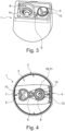
- FIG 3 a perspective view of a cartridge holder 1 is shown.
- the shape of the cartridge holder 1 which is only an example here, can be seen.
- This has at its upper end, which corresponds to the lower end according to the illustrations in the Figures 1 and 2 corresponds to a wall-like rectangular edge area within which the beverage outlet 5, the gas outlet 6 and the mandrel guide 8 are arranged.
- the cartridge holder 1 essentially has a dome shape, i.e. it is basically rounded at its end opposite the opening.
- a jet-forming element 15 is shown in the beverage outlet 5, which here is rib- and cross-shaped.
- the length of the beverage outlet 5, its cross-section and the jet-forming element 15 together serve to form and/or direct the emerging beverage jet.
- the gas outlet 6 has a smaller distance to the sealing film 19 than the beverage outlet 5, so that only gas can exit from the gas outlet 6. However, the gas can flow out of the gas outlet 6 in any direction, so that the gas outlet 6 does not have to have any such jet-forming elements. A certain minimum length of the gas outlet is also required. 6 is not decisive, so that it, as shown here, has a simple and, in particular, in comparison with the mandrel guide 8 and/or the beverage outlet 5, a lower opening (according to the orientation shown here).
- FIG 4 a top view of the cartridge holder 1 from the side of the connection area 2 is now shown.
- This embodiment also corresponds essentially to the embodiments already explained above, so that the relevant statements are also relevant here.
- the cartridge holder 1 has an essentially circular cross-section, with a flattening in the area of the fluid supply 4 and the compressed air connection 9, in order to enable easier coupling to the beverage preparation machine.
- the area of the cartridge holder 24 that receives the cartridge holder 1 is preferably designed in such a way that it receives the cartridge holder 1 in a form-fitting and/or force-fitting manner.
- the flattened area also advantageously ensures a preferred orientation, so that a reliable coupling to the beverage preparation machine takes place.
- the bow-like shape of the flow-forming element 13 which in the present case is molded onto the mandrel guide 8, wherein the flow-forming element 13, the mandrel guide 8, the connecting region 2, the gas outlet 6, the beverage outlet 5 and/or the residue outlet 7 are preferably molded in one piece.
- the cartridge 16 and/or the cartridge holder are made of a plastic material, in particular by means of an injection molding or blow molding process.
- the piercing mandrel 15 is manufactured separately from the same materials and/or using the same processes and then inserted into the cartridge holder 1.
- the piercing mandrel 15 is manufactured at the same time as the cartridge holder 1.
- the design of the residue outlet 7 can also be seen.
- the residue outlet 7 has a substantially oval cross-section and a circular segment-shaped area in which the residue outlet 7 is provided is excluded from the substantially circular cross-section of the beverage outlet 5.
- the beverage outlet 5 and the residue outlet 7 together form an essentially circular cross-section.
- the residue outlet 7 is arranged in the deepest area of the mixing chamber 3. As shown here, this can then merge downstream into the beverage outlet 5.
- the gas outlet 6 and the mandrel guide 8 are also connected here by a rounded section in order to improve the flow conditions in the mixing chamber 3.
- connection area 2 ribs protruding inwards, i.e. in the direction of the mixing chamber 3, can be seen, which serve as spacers for the cartridge 16, so that correct assembly of the cartridge system, also by the user if necessary, is ensured.
- FIGs 5 and 6 are schematic cross sections of a cartridge system inserted into a cartridge holder 24 of a beverage preparation machine of a beverage preparation system according to an exemplary embodiment of the present invention.
- the representations differ in that in Figure 5 the piercing mandrel 14 has just pierced the sealing foil 19 with its tip, while in Figure 6 a later position is shown. Both representations show positions of the piercing mandrel 14 between the retracted and the fully extended position.
- the cartridge 16 and the beverage preparation machine are only indicated for reasons of clarity.
- the cartridge 16 can be seen at the top edge of the drawing and comprises at least one flange 18, with which the cartridge 16 is connected in a form-fitting and/or force-fitting manner to the cartridge holder 1 via the connection area 2.
- the cartridge 16 can also have two vertically spaced, circumferential flanges.
- the sealing film 19 is sealed onto the flange, which thus represents the outermost element of the cartridge 16.
- the tip of the piercing mandrel 14 has just pierced the sealing film 19.
- the compressed air connection 9 is not yet fluidically connected to the compressed air outlet 10 and preferably essentially no beverage substance can get from the reservoir 17 into the mixing chamber 3.
- the actuator element 23 of the beverage preparation machine is shown at a distance from the piercing mandrel 14, but the person skilled in the art will understand that the piercing mandrel 14 is preferably transferred from the retracted to the extended position by a permanent contact between an actuator element holder of the piercing mandrel 14 and the actuator element 23, in particular by a permanent application of force, here in a vertical upward direction.
- a coupling element 20 of the beverage preparation machine has already come into contact with the fluid supply 4 and the compressed air connection 9, wherein in particular guide surfaces of the coupling element 20 interact with the conical surfaces of the fluid supply 4 and the compressed air connection 9 in order to ensure a fluid-tight and secure coupling.
- the coupling element 20 here has both an inner liquid line 22 and an inner compressed air line 21, which are each indirectly connected to a liquid reservoir of the beverage preparation machine or an external liquid supply or a compressed air source of the beverage preparation machine or an external compressed air supply.
- liquid conditioning system which is intended, for example, to carbonate and/or cool the liquid, in particular water, and to introduce it under pressure into the liquid line 22.
- the carbonated and cooled water flows through the fluid supply 4 into the mixing chamber 3, whereby the flow shaping element 13 ensures that a largely laminar flow is maintained.
- the piercing mandrel 14 has penetrated through the sealing foil 19 to such an extent that the compressed air outlet 10 is arranged within the reservoir 17 and the channel provided on the outside of the piercing mandrel 14, in particular in the form of a groove, provides a path for the Beverage substance is provided from the reservoir 17 into the mixing chamber 3.
- the compressed air line 11 of the piercing mandrel 14 already partially overlaps with the compressed air connection 9, so that a partial fluid connection is present and compressed air from the machine-side compressed air line 21 can reach the reservoir 17 and helps to transfer the beverage substance into the mixing chamber 3, where it is mixed with the optionally carbonated and/or cooled water before it is dispensed via the beverage outlet 5 into a beverage container arranged underneath.
- the beverage preparation machine can be operated with different parameters and/or the cartridge holder 1 is designed accordingly.
- the temperature and/or the degree of carbonation of the water can be controlled.
- the dilution ratio can be controlled, in particular by a user.
- the volume flow of the liquid for example water
- the volume flow of the beverage substance can also be controlled. This can be done via the volume flow of the compressed air, but also, for example, via the number or size of the channels of the piercing mandrel 14 and/or the diameter of the piercing mandrel 14 passing through the sealing film 19.
- gas released during preparation in the case of carbonated water in particular carbon dioxide, is discharged from the cartridge holder 1 into the environment via the gas outlet 6.
Landscapes
- Engineering & Computer Science (AREA)
- Food Science & Technology (AREA)
- Devices For Dispensing Beverages (AREA)
- Apparatus For Making Beverages (AREA)
Claims (15)
- Réceptacle de cartouche (1) destiné à produire une boisson au moyen d'une cartouche (16), lequel réceptacle de cartouche comprend un réservoir (17) rempli d'une substance pour boisson et fermé par un élément d'étanchéité, notamment un film d'étanchéité (19), le réceptacle de cartouche (1) comportant une zone de liaison (2) destinée à être reliée à la cartouche (16) et le réceptacle de cartouche (1) pourvu de la cartouche (16) pouvant être inséré dans une machine de préparation de boissons, le réceptacle de cartouche (1) comportant une chambre de mélange (3) qui peut être reliée fluidiquement au réservoir (17) et une alimentation en fluide (4) qui débouche dans la chambre de mélange (3) et qui est destinée à introduire du liquide dans la chambre de mélange (3), le réceptacle de cartouche (1) comportant un dispositif de déchargement de cartouche destiné à transférer au moins partiellement la substance pour boisson du réservoir (17) jusque dans la chambre de mélange (3), le réceptacle de cartouche (1) comportant une sortie de boisson (5) destinée à évacuer une boisson de la chambre de mélange (3), en particulier directement, jusque dans un récipient à boisson, le réceptacle de cartouche (1) comportant en outre une sortie de gaz (6) destinée à évacuer du réceptacle de cartouche (1) un gaz libéré dans la chambre de mélange (3), en particulier du dioxyde de carbone, caractérisé en ce qu'une surface d'entrée supérieure de la sortie de gaz (6) est disposée plus haut qu'une surface d'entrée supérieure de la sortie de boisson (5).
- Réceptacle de cartouche (1) selon la revendication 1, caractérisé en ce que la sortie de gaz (6) et/ou la sortie de boisson (5) est sensiblement en forme de canal, notamment allongée longitudinalement, et/ou en ce que l'alimentation en fluide (4) est une ouverture d'alimentation en fluide qui est conçue pour établir une liaison fluidique avec une conduite de fluide de la machine de préparation de boissons.
- Réceptacle de cartouche (1) selon l'une des revendications précédentes, caractérisé en ce que la sortie de gaz (6) est disposée sensiblement au milieu dans le réceptacle de cartouche (1).
- Réceptacle de cartouche (1) selon l'une des revendications précédentes, caractérisé en ce qu'une ouverture de la sortie de boisson (5) est plus grande qu'une ouverture de sortie de gaz (6), la sortie de boisson (5) ayant, en particulier au moins par portions, une aire en coupe transversale supérieure à celle de la sortie de gaz (6).
- Réceptacle de cartouche (1) selon l'une des revendications précédentes, caractérisé en ce que le dispositif de déchargement de cartouche comprend un raccord d'air comprimé (9) et une conduite d'air comprimé (11) qui s'étend du raccord d'air comprimé (9) à une sortie d'air comprimé (10), la sortie d'air comprimé (10) faisant saillie notamment en direction du réservoir (17) de la cartouche, le raccord d'air comprimé (9) étant conçu pour introduire de l'air comprimé dans le réservoir (17), le dispositif de déchargement de cartouche étant conçu de telle sorte que la substance de boisson puisse être transférée du réservoir (17) jusque dans la chambre de mélange (3) par l'air comprimé.
- Réceptacle de cartouche (1) selon l'une des revendications précédentes, caractérisé en ce que le dispositif de déchargement de cartouche comprend un guide de mandrin (8) et un mandrin de perçage (14) qui est monté de manière coulissante à l'intérieur du guide de mandrin (8), notamment dans une direction, le mandrin de perçage (14) pouvant coulisser, en particulier par le biais d'un élément d'actionnement (23) de la machine de préparation de boissons, entre une position rétractée, dans laquelle le mandrin de perçage (14) est espacé de l'élément d'étanchéité, et une position déployée dans laquelle le mandrin de perçage (14) transperce l'élément d'étanchéité et fait saillie dans le réservoir (17), la conduite d'air comprimé (11) étant de préférence intégrée dans le mandrin de perçage (14).
- Réceptacle de cartouche (1) selon l'une des revendications précédentes, caractérisé en ce que la sortie de gaz (6), la sortie de boisson (5) et/ou le guide de mandrin (8) ont une section transversale sensiblement circulaire.
- Réceptacle de cartouche (1) selon l'une des revendications précédentes, caractérisé en ce que la sortie de gaz (6) est disposée entre le guide de mandrin (8) et/ou l'alimentation en fluide (4) et la sortie de boisson (5).
- Réceptacle de cartouche (1) selon l'une des revendications précédentes, caractérisé en ce que la sortie de boisson (5) comprend un élément de formation de jet (15), l'élément de formation de jet (15) étant notamment en forme de croix.
- Réceptacle de cartouche (1) selon l'une des revendications précédentes, caractérisé en ce qu'il comporte un élément de formation d'écoulement (13) dans une zone dirigée vers l'alimentation en fluide (4) afin d'assurer un écoulement laminaire d'un liquide amené dans la chambre de mélange (3) par l'alimentation en fluide (4).
- Système de cartouche destiné à produire une boisson, le système de cartouche pouvant être inséré dans une machine de préparation de boissons, le système de cartouche comprenant une cartouche (16) pourvu d'un réservoir (17) rempli d'une substance de boisson, et un réceptacle de cartouche (1), selon l'une des revendications précédentes, qui est relié à la cartouche (16), le réceptacle de cartouche (1) et la cartouche (16) étant reliés l'un à l'autre dans une zone de liaison (2), la cartouche (16) comportant une ouverture de cartouche, l'ouverture de cartouche comportant dans une zone de bord un élément d'étanchéité, en particulier un film d'étanchéité (19), l'élément d'étanchéité fermant hermétiquement le réservoir (17) de manière étanche aux fluides par rapport au réceptacle de cartouche (1).
- Système de cartouche selon la revendication précédente, caractérisé en ce que la distance entre l'ouverture de la sortie de gaz (6), dirigée vers l'élément d'étanchéité, et l'élément d'étanchéité est comprise entre 0,1 mm et 1,0 mm, de préférence entre 0,3 mm et 0,8 mm, notamment entre 0,4 mm et 0,6 mm.
- Système de préparation de boissons comprenant une machine de préparation de boissons et un système de cartouche selon l'une des revendications 11 à 12, la machine de préparation de boissons comprenant un support de cartouche (24), notamment de type balcon, dans lequel le système de cartouche peut être inséré, la machine de préparation de boissons comprenant en outre un réservoir de liquide, un système de conditionnement de liquide destiné à conditionner un liquide provenant du réservoir de liquide, notamment chauffer, refroidir et/ou gazéifier le liquide, un élément d'actionnement (23) destiné à actionner le dispositif de déchargement de cartouche, en particulier le mandrin de perçage (14), un système d'alimentation en fluide qui peut être accouplé au système de cartouche et qui est prévu pour introduire le liquide conditionné dans la chambre de mélange (3) par le biais de l'alimentation en fluide et introduire de préférence de l'air comprimé dans la conduite d'air comprimé (11) au niveau du raccord d'air comprimé (9), et un dispositif de commande destiné à commander le système de conditionnement de liquide, le système d'alimentation en fluide et/ou l'élément d'actionnement.
- Système de préparation de boissons selon la revendication 13, caractérisé en ce que la machine de préparation de boissons comporte un moyen de verrouillage destiné à verrouiller de manière réversible le système de cartouche dans le support de cartouche (24), le moyen de verrouillage pouvant être actionné par un utilisateur.
- Procédé de préparation d'une boisson à l'aide d'un système de préparation de boissons selon l'une des revendications 13 ou 14, caractérisé par les étapes suivantes:- insérer un système de cartouche, composé d'une cartouche (16) et d'un réceptacle de cartouche (1), dans le support de cartouche (24),- établir une liaison fluidique entre le système d'alimentation en fluide et le réceptacle de cartouche (1),- activer l'élément d'actionnement (23) afin d'actionner le dispositif de déchargement de cartouche, notamment par transfert du mandrin de perçage (14) de la position rétractée à la position déployée, ce qui provoque une perforation du moyen d'étanchéité,- transférer la substance pour boisson du réservoir (17) de la cartouche (16) jusque dans la chambre de mélange (3) du réceptacle de cartouche (1), notamment par introduction d'air comprimé dans la cartouche (16) par le biais du raccord d'air comprimé (9),- introduire un liquide dans la chambre de mélange (3) du réceptacle de cartouche (1) par le biais de l'alimentation en fluide (4) et- évacuer la boisson, produite dans la chambre de mélange (3) par mélange de la substance pour boisson au liquide, par la sortie de boisson (5),- évacuer le gaz libéré pendant le mélange, en particulier le dioxyde de carbone, par la sortie de gaz (6) .
Applications Claiming Priority (2)
| Application Number | Priority Date | Filing Date | Title |
|---|---|---|---|
| DE102021200070 | 2021-01-07 | ||
| PCT/EP2022/050160 WO2022148785A1 (fr) | 2021-01-07 | 2022-01-05 | Dispositif de réception pour cartouche, système de cartouche, système de préparation de boissons et procédé de préparation d'une boisson |
Publications (3)
| Publication Number | Publication Date |
|---|---|
| EP4274452A1 EP4274452A1 (fr) | 2023-11-15 |
| EP4274452B1 true EP4274452B1 (fr) | 2025-03-05 |
| EP4274452C0 EP4274452C0 (fr) | 2025-03-05 |
Family
ID=79731184
Family Applications (1)
| Application Number | Title | Priority Date | Filing Date |
|---|---|---|---|
| EP22700301.9A Active EP4274452B1 (fr) | 2021-01-07 | 2022-01-05 | Dispositif de réception pour cartouche, système de cartouche, système de préparation de boissons et procédé de préparation d'une boisson |
Country Status (12)
| Country | Link |
|---|---|
| US (1) | US20240032725A1 (fr) |
| EP (1) | EP4274452B1 (fr) |
| JP (1) | JP7597938B2 (fr) |
| KR (1) | KR20230128373A (fr) |
| CN (1) | CN116848058A (fr) |
| AU (1) | AU2022206545B2 (fr) |
| CA (1) | CA3202180A1 (fr) |
| ES (1) | ES3029858T3 (fr) |
| HU (1) | HUE071120T2 (fr) |
| IL (1) | IL303459A (fr) |
| PL (1) | PL4274452T3 (fr) |
| WO (1) | WO2022148785A1 (fr) |
Families Citing this family (5)
| Publication number | Priority date | Publication date | Assignee | Title |
|---|---|---|---|---|
| CN120417995A (zh) * | 2022-12-02 | 2025-08-01 | 积云咖啡公司 | 用于生成饮料的系统 |
| USD1113343S1 (en) | 2023-09-20 | 2026-02-17 | The Cumulus Coffee Company | Pod |
| USD1111812S1 (en) | 2023-09-20 | 2026-02-10 | The Cumulus Coffee Company | Pod |
| USD1113443S1 (en) | 2024-05-14 | 2026-02-17 | The Cumulus Coffee Company | Pod |
| USD1113444S1 (en) | 2024-05-14 | 2026-02-17 | The Cumulus Coffee Company | Pod |
Citations (1)
| Publication number | Priority date | Publication date | Assignee | Title |
|---|---|---|---|---|
| EP2017220A1 (fr) * | 2007-07-19 | 2009-01-21 | Nestec, Ltd. | Dispositif de distribution de liquide |
Family Cites Families (9)
| Publication number | Priority date | Publication date | Assignee | Title |
|---|---|---|---|---|
| US7658213B1 (en) * | 2005-09-29 | 2010-02-09 | Anderson Chemical Company | Fluid dispensing system |
| EP2017221A1 (fr) * | 2007-07-19 | 2009-01-21 | Nestec, Ltd. | Dispositif de distribution de liquide |
| US8505777B2 (en) * | 2010-08-16 | 2013-08-13 | Lancer Corporation | Method and apparatus for a sanitizable mixing nozzle |
| ITRN20110059A1 (it) * | 2011-08-12 | 2013-02-13 | Celli Spa | Valvola post-mix per colonne di erogazione, macchine erogatrici di bevande o simili. |
| WO2015139062A1 (fr) | 2013-12-11 | 2015-09-17 | Broodryk Bergen | Appareil et système de distribution de fluide |
| ES2939370T3 (es) | 2016-01-12 | 2023-04-21 | Freezio Ag | Sistema de dispensador con soporte para cartucho |
| RS62028B1 (sr) | 2017-06-26 | 2021-07-30 | Freezio Ag | Uređaj za proizvodnju napitka |
| CN107440523B (zh) * | 2017-08-25 | 2023-09-08 | 宁波心想科技有限公司 | 一种饮料制备装置的出液结构 |
| US11617994B2 (en) * | 2018-02-08 | 2023-04-04 | Bunn-O-Matic Corporation | Gas infuser for liquids |
-
2022
- 2022-01-05 CA CA3202180A patent/CA3202180A1/fr active Pending
- 2022-01-05 EP EP22700301.9A patent/EP4274452B1/fr active Active
- 2022-01-05 US US18/268,367 patent/US20240032725A1/en active Pending
- 2022-01-05 WO PCT/EP2022/050160 patent/WO2022148785A1/fr not_active Ceased
- 2022-01-05 CN CN202280009351.1A patent/CN116848058A/zh active Pending
- 2022-01-05 KR KR1020237026848A patent/KR20230128373A/ko not_active Ceased
- 2022-01-05 AU AU2022206545A patent/AU2022206545B2/en active Active
- 2022-01-05 ES ES22700301T patent/ES3029858T3/es active Active
- 2022-01-05 PL PL22700301.9T patent/PL4274452T3/pl unknown
- 2022-01-05 JP JP2023541261A patent/JP7597938B2/ja active Active
- 2022-01-05 IL IL303459A patent/IL303459A/en unknown
- 2022-01-05 HU HUE22700301A patent/HUE071120T2/hu unknown
Patent Citations (1)
| Publication number | Priority date | Publication date | Assignee | Title |
|---|---|---|---|---|
| EP2017220A1 (fr) * | 2007-07-19 | 2009-01-21 | Nestec, Ltd. | Dispositif de distribution de liquide |
Also Published As
| Publication number | Publication date |
|---|---|
| CA3202180A1 (fr) | 2022-07-14 |
| AU2022206545A9 (en) | 2024-09-12 |
| HUE071120T2 (hu) | 2025-08-28 |
| JP7597938B2 (ja) | 2024-12-10 |
| EP4274452A1 (fr) | 2023-11-15 |
| KR20230128373A (ko) | 2023-09-04 |
| WO2022148785A1 (fr) | 2022-07-14 |
| EP4274452C0 (fr) | 2025-03-05 |
| AU2022206545A1 (en) | 2023-07-06 |
| AU2022206545B2 (en) | 2024-09-26 |
| IL303459A (en) | 2023-08-01 |
| ES3029858T3 (en) | 2025-06-25 |
| US20240032725A1 (en) | 2024-02-01 |
| CN116848058A (zh) | 2023-10-03 |
| JP2024503634A (ja) | 2024-01-26 |
| PL4274452T3 (pl) | 2025-07-07 |
Similar Documents
| Publication | Publication Date | Title |
|---|---|---|
| EP4304976B1 (fr) | Machine de préparation de boissons comprenant un moyen de verrouillage et un élément de couplage et système de préparation de boissons | |
| EP3674255B1 (fr) | Distributeur doté d'une fixation de cartouche | |
| EP4274452B1 (fr) | Dispositif de réception pour cartouche, système de cartouche, système de préparation de boissons et procédé de préparation d'une boisson | |
| EP4304975B1 (fr) | Machine de préparation de boisson pourvue d'un mécanisme d'entraînement et d'un système de préparation de boisson | |
| EP3716823B2 (fr) | Logement de cartouche, système de cartouche, machine de préparation de boissons et procédé de préparation d'une boisson | |
| EP4003899B1 (fr) | Procédé de production d'un système de cartouche | |
| EP4313843B1 (fr) | Cartouche a inserer dans un appareil de preparation de boisson, procédé d'utilisation d'une telle cartouche | |
| EP4232399B1 (fr) | Système de cartouche, machine de préparation de boissons et procédé de production d'un système de cartouche | |
| EP3661860A1 (fr) | Capsule et système de boisson pour la préparation d'une boisson | |
| DE102007001609A1 (de) | Vorrichtung zur Bereitstellung eines inbesondere kohlensäurehaltigen Getränks | |
| WO2025099239A1 (fr) | Pointe de perforation, support de cartouche, système de préparation d'une boisson, procédé de préparation d'une boisson et utilisation d'une pointe de perforation |
Legal Events
| Date | Code | Title | Description |
|---|---|---|---|
| STAA | Information on the status of an ep patent application or granted ep patent |
Free format text: STATUS: UNKNOWN |
|
| STAA | Information on the status of an ep patent application or granted ep patent |
Free format text: STATUS: THE INTERNATIONAL PUBLICATION HAS BEEN MADE |
|
| PUAI | Public reference made under article 153(3) epc to a published international application that has entered the european phase |
Free format text: ORIGINAL CODE: 0009012 |
|
| STAA | Information on the status of an ep patent application or granted ep patent |
Free format text: STATUS: REQUEST FOR EXAMINATION WAS MADE |
|
| 17P | Request for examination filed |
Effective date: 20230807 |
|
| AK | Designated contracting states |
Kind code of ref document: A1 Designated state(s): AL AT BE BG CH CY CZ DE DK EE ES FI FR GB GR HR HU IE IS IT LI LT LU LV MC MK MT NL NO PL PT RO RS SE SI SK SM TR |
|
| DAV | Request for validation of the european patent (deleted) | ||
| DAX | Request for extension of the european patent (deleted) | ||
| GRAP | Despatch of communication of intention to grant a patent |
Free format text: ORIGINAL CODE: EPIDOSNIGR1 |
|
| STAA | Information on the status of an ep patent application or granted ep patent |
Free format text: STATUS: GRANT OF PATENT IS INTENDED |
|
| INTG | Intention to grant announced |
Effective date: 20240821 |
|
| GRAS | Grant fee paid |
Free format text: ORIGINAL CODE: EPIDOSNIGR3 |
|
| GRAA | (expected) grant |
Free format text: ORIGINAL CODE: 0009210 |
|
| STAA | Information on the status of an ep patent application or granted ep patent |
Free format text: STATUS: THE PATENT HAS BEEN GRANTED |
|
| AK | Designated contracting states |
Kind code of ref document: B1 Designated state(s): AL AT BE BG CH CY CZ DE DK EE ES FI FR GB GR HR HU IE IS IT LI LT LU LV MC MK MT NL NO PL PT RO RS SE SI SK SM TR |
|
| REG | Reference to a national code |
Ref country code: GB Ref legal event code: FG4D Free format text: NOT ENGLISH |
|
| REG | Reference to a national code |
Ref country code: CH Ref legal event code: EP |
|
| REG | Reference to a national code |
Ref country code: DE Ref legal event code: R096 Ref document number: 502022003091 Country of ref document: DE |
|
| REG | Reference to a national code |
Ref country code: IE Ref legal event code: FG4D Free format text: LANGUAGE OF EP DOCUMENT: GERMAN |
|
| U01 | Request for unitary effect filed |
Effective date: 20250401 |
|
| U07 | Unitary effect registered |
Designated state(s): AT BE BG DE DK EE FI FR IT LT LU LV MT NL PT RO SE SI Effective date: 20250407 |
|
| REG | Reference to a national code |
Ref country code: ES Ref legal event code: FG2A Ref document number: 3029858 Country of ref document: ES Kind code of ref document: T3 Effective date: 20250625 |
|
| PG25 | Lapsed in a contracting state [announced via postgrant information from national office to epo] |
Ref country code: RS Free format text: LAPSE BECAUSE OF FAILURE TO SUBMIT A TRANSLATION OF THE DESCRIPTION OR TO PAY THE FEE WITHIN THE PRESCRIBED TIME-LIMIT Effective date: 20250605 |
|
| PG25 | Lapsed in a contracting state [announced via postgrant information from national office to epo] |
Ref country code: NO Free format text: LAPSE BECAUSE OF FAILURE TO SUBMIT A TRANSLATION OF THE DESCRIPTION OR TO PAY THE FEE WITHIN THE PRESCRIBED TIME-LIMIT Effective date: 20250605 |
|
| PG25 | Lapsed in a contracting state [announced via postgrant information from national office to epo] |
Ref country code: HR Free format text: LAPSE BECAUSE OF FAILURE TO SUBMIT A TRANSLATION OF THE DESCRIPTION OR TO PAY THE FEE WITHIN THE PRESCRIBED TIME-LIMIT Effective date: 20250305 |
|
| PG25 | Lapsed in a contracting state [announced via postgrant information from national office to epo] |
Ref country code: GR Free format text: LAPSE BECAUSE OF FAILURE TO SUBMIT A TRANSLATION OF THE DESCRIPTION OR TO PAY THE FEE WITHIN THE PRESCRIBED TIME-LIMIT Effective date: 20250606 |
|
| REG | Reference to a national code |
Ref country code: SK Ref legal event code: T3 Ref document number: E 46496 Country of ref document: SK |
|
| REG | Reference to a national code |
Ref country code: HU Ref legal event code: AG4A Ref document number: E071120 Country of ref document: HU |
|
| PG25 | Lapsed in a contracting state [announced via postgrant information from national office to epo] |
Ref country code: SM Free format text: LAPSE BECAUSE OF FAILURE TO SUBMIT A TRANSLATION OF THE DESCRIPTION OR TO PAY THE FEE WITHIN THE PRESCRIBED TIME-LIMIT Effective date: 20250305 |
|
| PG25 | Lapsed in a contracting state [announced via postgrant information from national office to epo] |
Ref country code: CZ Free format text: LAPSE BECAUSE OF FAILURE TO SUBMIT A TRANSLATION OF THE DESCRIPTION OR TO PAY THE FEE WITHIN THE PRESCRIBED TIME-LIMIT Effective date: 20250305 |
|
| PG25 | Lapsed in a contracting state [announced via postgrant information from national office to epo] |
Ref country code: IS Free format text: LAPSE BECAUSE OF FAILURE TO SUBMIT A TRANSLATION OF THE DESCRIPTION OR TO PAY THE FEE WITHIN THE PRESCRIBED TIME-LIMIT Effective date: 20250705 |
|
| PLBE | No opposition filed within time limit |
Free format text: ORIGINAL CODE: 0009261 |
|
| STAA | Information on the status of an ep patent application or granted ep patent |
Free format text: STATUS: NO OPPOSITION FILED WITHIN TIME LIMIT |
|
| REG | Reference to a national code |
Ref country code: CH Ref legal event code: L10 Free format text: ST27 STATUS EVENT CODE: U-0-0-L10-L00 (AS PROVIDED BY THE NATIONAL OFFICE) Effective date: 20260114 |
|
| 26N | No opposition filed |
Effective date: 20251208 |