EP4004256B1 - Composite nickel-phosphore multicouche - Google Patents
Composite nickel-phosphore multicouche Download PDFInfo
- Publication number
- EP4004256B1 EP4004256B1 EP20747144.2A EP20747144A EP4004256B1 EP 4004256 B1 EP4004256 B1 EP 4004256B1 EP 20747144 A EP20747144 A EP 20747144A EP 4004256 B1 EP4004256 B1 EP 4004256B1
- Authority
- EP
- European Patent Office
- Prior art keywords
- composite
- layer
- metallic
- nip
- nip layer
- Prior art date
- Legal status (The legal status is an assumption and is not a legal conclusion. Google has not performed a legal analysis and makes no representation as to the accuracy of the status listed.)
- Active
Links
Images
Classifications
-
- C—CHEMISTRY; METALLURGY
- C23—COATING METALLIC MATERIAL; COATING MATERIAL WITH METALLIC MATERIAL; CHEMICAL SURFACE TREATMENT; DIFFUSION TREATMENT OF METALLIC MATERIAL; COATING BY VACUUM EVAPORATION, BY SPUTTERING, BY ION IMPLANTATION OR BY CHEMICAL VAPOUR DEPOSITION, IN GENERAL; INHIBITING CORROSION OF METALLIC MATERIAL OR INCRUSTATION IN GENERAL
- C23C—COATING METALLIC MATERIAL; COATING MATERIAL WITH METALLIC MATERIAL; SURFACE TREATMENT OF METALLIC MATERIAL BY DIFFUSION INTO THE SURFACE, BY CHEMICAL CONVERSION OR SUBSTITUTION; COATING BY VACUUM EVAPORATION, BY SPUTTERING, BY ION IMPLANTATION OR BY CHEMICAL VAPOUR DEPOSITION, IN GENERAL
- C23C18/00—Chemical coating by decomposition of either liquid compounds or solutions of the coating forming compounds, without leaving reaction products of surface material in the coating; Contact plating
- C23C18/16—Chemical coating by decomposition of either liquid compounds or solutions of the coating forming compounds, without leaving reaction products of surface material in the coating; Contact plating by reduction or substitution, e.g. electroless plating
- C23C18/1601—Process or apparatus
- C23C18/1633—Process of electroless plating
- C23C18/1646—Characteristics of the product obtained
- C23C18/165—Multilayered product
- C23C18/1651—Two or more layers only obtained by electroless plating
-
- B—PERFORMING OPERATIONS; TRANSPORTING
- B32—LAYERED PRODUCTS
- B32B—LAYERED PRODUCTS, i.e. PRODUCTS BUILT-UP OF STRATA OF FLAT OR NON-FLAT, e.g. CELLULAR OR HONEYCOMB, FORM
- B32B15/00—Layered products comprising a layer of metal
- B32B15/04—Layered products comprising a layer of metal comprising metal as the main or only constituent of a layer, which is next to another layer of the same or of a different material
- B32B15/043—Layered products comprising a layer of metal comprising metal as the main or only constituent of a layer, which is next to another layer of the same or of a different material of metal
-
- C—CHEMISTRY; METALLURGY
- C23—COATING METALLIC MATERIAL; COATING MATERIAL WITH METALLIC MATERIAL; CHEMICAL SURFACE TREATMENT; DIFFUSION TREATMENT OF METALLIC MATERIAL; COATING BY VACUUM EVAPORATION, BY SPUTTERING, BY ION IMPLANTATION OR BY CHEMICAL VAPOUR DEPOSITION, IN GENERAL; INHIBITING CORROSION OF METALLIC MATERIAL OR INCRUSTATION IN GENERAL
- C23C—COATING METALLIC MATERIAL; COATING MATERIAL WITH METALLIC MATERIAL; SURFACE TREATMENT OF METALLIC MATERIAL BY DIFFUSION INTO THE SURFACE, BY CHEMICAL CONVERSION OR SUBSTITUTION; COATING BY VACUUM EVAPORATION, BY SPUTTERING, BY ION IMPLANTATION OR BY CHEMICAL VAPOUR DEPOSITION, IN GENERAL
- C23C18/00—Chemical coating by decomposition of either liquid compounds or solutions of the coating forming compounds, without leaving reaction products of surface material in the coating; Contact plating
- C23C18/16—Chemical coating by decomposition of either liquid compounds or solutions of the coating forming compounds, without leaving reaction products of surface material in the coating; Contact plating by reduction or substitution, e.g. electroless plating
- C23C18/1601—Process or apparatus
- C23C18/1633—Process of electroless plating
- C23C18/1655—Process features
- C23C18/1662—Use of incorporated material in the solution or dispersion, e.g. particles, whiskers, wires
-
- C—CHEMISTRY; METALLURGY
- C23—COATING METALLIC MATERIAL; COATING MATERIAL WITH METALLIC MATERIAL; CHEMICAL SURFACE TREATMENT; DIFFUSION TREATMENT OF METALLIC MATERIAL; COATING BY VACUUM EVAPORATION, BY SPUTTERING, BY ION IMPLANTATION OR BY CHEMICAL VAPOUR DEPOSITION, IN GENERAL; INHIBITING CORROSION OF METALLIC MATERIAL OR INCRUSTATION IN GENERAL
- C23C—COATING METALLIC MATERIAL; COATING MATERIAL WITH METALLIC MATERIAL; SURFACE TREATMENT OF METALLIC MATERIAL BY DIFFUSION INTO THE SURFACE, BY CHEMICAL CONVERSION OR SUBSTITUTION; COATING BY VACUUM EVAPORATION, BY SPUTTERING, BY ION IMPLANTATION OR BY CHEMICAL VAPOUR DEPOSITION, IN GENERAL
- C23C18/00—Chemical coating by decomposition of either liquid compounds or solutions of the coating forming compounds, without leaving reaction products of surface material in the coating; Contact plating
- C23C18/16—Chemical coating by decomposition of either liquid compounds or solutions of the coating forming compounds, without leaving reaction products of surface material in the coating; Contact plating by reduction or substitution, e.g. electroless plating
- C23C18/1601—Process or apparatus
- C23C18/1633—Process of electroless plating
- C23C18/1689—After-treatment
- C23C18/1692—Heat-treatment
-
- C—CHEMISTRY; METALLURGY
- C23—COATING METALLIC MATERIAL; COATING MATERIAL WITH METALLIC MATERIAL; CHEMICAL SURFACE TREATMENT; DIFFUSION TREATMENT OF METALLIC MATERIAL; COATING BY VACUUM EVAPORATION, BY SPUTTERING, BY ION IMPLANTATION OR BY CHEMICAL VAPOUR DEPOSITION, IN GENERAL; INHIBITING CORROSION OF METALLIC MATERIAL OR INCRUSTATION IN GENERAL
- C23C—COATING METALLIC MATERIAL; COATING MATERIAL WITH METALLIC MATERIAL; SURFACE TREATMENT OF METALLIC MATERIAL BY DIFFUSION INTO THE SURFACE, BY CHEMICAL CONVERSION OR SUBSTITUTION; COATING BY VACUUM EVAPORATION, BY SPUTTERING, BY ION IMPLANTATION OR BY CHEMICAL VAPOUR DEPOSITION, IN GENERAL
- C23C18/00—Chemical coating by decomposition of either liquid compounds or solutions of the coating forming compounds, without leaving reaction products of surface material in the coating; Contact plating
- C23C18/16—Chemical coating by decomposition of either liquid compounds or solutions of the coating forming compounds, without leaving reaction products of surface material in the coating; Contact plating by reduction or substitution, e.g. electroless plating
- C23C18/31—Coating with metals
- C23C18/32—Coating with nickel, cobalt or mixtures thereof with phosphorus or boron
Definitions
- the invention provides a system comprising a substrate and an electroless composite coating comprising a layered structure alternating a metallic NiP layer and a composite NiP layer.
- the invention further pertains to the method of preparation of said system and to its uses.
- Solid particle erosion is material removal/damage to a solid surface produced by repeated impacts of solid particles. It is to be expected whenever hard particles are entrained in a gas or liquid medium impinging on a solid at any significant velocity.
- the solid-liquid erosion is known as slurry erosion. Slurry erosion has become a serious problem for the performance, reliability, and service life of slurry equipment used in many industrial applications such as: mining machinery components, hydraulic transport of solids in pipelines, marine, oil gas and power generation industries.
- Electroless Ni-P coatings have been well known as a hard coating for industrial applications, due to their good corrosion and wear resistance properties. They are usually obtained by co-depositing particulate materials, such as ceramics, diamond and fluoropolymers and carbides of silicon, tungsten and chromium. This valuable process can coat not only electrically conductive materials including graphite but also fabrics, insulators like plastics, rubber etc.
- electroless Ni-composite plated substrates examples include US 2009/0011136 , US 20111/0162751 , US2013/0143031 , and US2016/0010214 .
- US4358923A discloses processes and articles for composite electroless coatings comprising at least two distinct layers, the first layer comprising a metal and/or a metal alloy plus particulate matter and the second layer comprising a metal and/or a metal alloy and being substantially free of particulate matter.
- US2011226144A1 discloses a doctor blade for wiping printing ink off a surface of a printing plate and/or for use as a paper doctor knife; at least the working edge region of the doctor blade is covered with a coating on the basis of a nickel-phosphorus alloy; in some embodiments, the coating comprises a composite layer of NiP, containing particles of different size and nature, and a metallic layer of NiP.
- the major advantages of the electroless Ni-P plating deposition process include the formation of a uniform deposit on irregular surfaces, direct deposition on surface-activated non-conductors, and the formation of non-magnetic, low internal stress deposits. Furthermore, when accompanied by an appropriate post-heat treatment, the wear resistance of the coatings can be improved considerably. The effectiveness of using a composite electroless Ni-P-SiC coating system for cavitation erosion protection of steel has also been observed.
- the main application of the electroless Ni-P coatings is in the increase of wear resistance of parts in choke valves and in the protection of the inner/outer surface of the pipelines.
- Pipelines play an important role throughout the world as a means of transporting gases and liquids over long distances from their source to the supply. According to the environment and to the fluid, abrasion and erosion phenomena can degrade rapidly the wall of the pipeline, losing integrity. Hence, in the oil and gas field, in particular for the coating of the inner surfaces of the pipelines, a very high wear (abrasive/erosive) resistance is required combined with an improved corrosion protection to harsh environment. However, the combination of these two properties is hard to achieve through the traditional and commercially available technology of composite electroless deposition.
- the present invention relates to a system comprising a substrate and an electroless composite coating in contact with the substrate as claimed by claim 1.
- the composite NiP layer comprises P in amounts between 1 and 20 wt%, more preferably in an amount between 7 and 15 wt%.
- Ni and P together with any other metallic element, which may be present in the metallic and/or the composite layer form a so called metallic matrix.
- the amount of P is defined with respect to the total weight of the metallic matrix.
- the particles have average size between 10-5000 nm, more preferably between 50-3000 nm.
- the dispersed particles are a blend comprising first and second particles different in size and nature, preferably the first particles have average size between 100-5000 nm, more preferably between 500-3000 nm and the second particles have average size between 10-2000 nm, more preferably between 50-500 nm.
- the dispersed particles are boron carbide particles and/or silicon carbide nanoparticles.
- the metallic NiP layer and the composite NiP layer comprise the same amount of P with respect to Ni.
- the composite NiP layer consists essentially of Ni and P and the dispersed particles or of Ni, P, the dispersed particles and one or more further metallic element.
- the metallic NiP layer consists essentially of Ni and P or of Ni, P and one or more further metallic element.
- a layer alternation is defined as any alternation between a metallic and a composite layer or a composite and a metallic layer.
- the alternation occurs from 2 to 12 times, preferably from 3 to 11 times, more preferably 5, 7 or 9 times.
- an alternation of metallic/composite/metallic layers or composite/metallic/composite accounts for 2 times (3 layers) or an alternation of composite/metallic/composite/metallic layers for 3 times (4 layers).
- a coating with more than 12 alternations is still possible however it may become too expensive and time consuming to be produced.
- the layered structure consists of 3, 4, 5, 6, 7, 8, 9 or 10 layers, more preferably of 6, 8 or 10, even more preferably of 8 layers.
- the electroless composite coating consists of the layered structure of alternating metallic NiP layers and composite NiP layers.
- the layer formed over and in contact with the substrate is a metallic NiP layer and or preferably the outer layer is a composite NiP layer.
- the invention also provides a pipeline as claimed by claim 10, coated with the electroless composite coating as described above.
- the pipeline is coated with the electroless composite coating in its inner surface.
- the present invention in addition provides the use of the system of the invention to improve the resistance of a pipeline to chemical and mechanical degradation as claimed by claim 12.
- the present invention further provides a method to produce the system of the invention as claimed by claim 13. Said method comprises the following steps:
- the method includes a thermal treatment comprising heating the system after deposition of at least a layer at temperatures in the range 200-600 °C.
- the present invention relates to a system comprising a substrate and an electroless composite coating in contact with the substrate; the electroless composite coating comprising a layered structure alternating a metallic NiP layer, comprising Ni and P and a composite NiP layer comprising Ni, P and particles dispersed therein, wherein the dispersed particles are a blend comprising first and second particles wherein the first and the second particles are different in size and nature.
- the electroless composite coating consists of a layered structure alternating a metallic NiP layer, comprising Ni and P and a composite NiP layer comprising Ni, P and particles dispersed therein, wherein the dispersed particles are a blend comprising first and second particles wherein the first and the second particles are different in size and nature, and wherein the alternation is repeated 3 to 11 times, preferably 5, 7 or 9 times.
- the electroless composite coating consists of a layered structure alternating a metallic NiP layer, comprising Ni and P and a composite NiP layer comprising Ni, P and particles dispersed therein, wherein the dispersed particles are a blend comprising first and second particles wherein the first and the second particles are different in size and nature, for a total of 4, 6, 8, 10 layers, preferably, 6, 8, even more preferably 8.
- the invention pertains to an electroless composite coating comprising a layered structure alternating a metallic NiP layer comprising Ni and P; a composite NiP layer comprising Ni, P and dispersed particles; and a further NiP layer or composite NiP layer.
- the electroless composite coating comprises or preferably consists of a single or repeated layered structure of metallic NiP/composite NiP/metallic NiP layers or composite NiP/metallic NiP/composite NiP layers.
- the metallic NiP layer is different from the composite NiP layer.
- the metallic NiP layer does not contain any particles dispersed therein.
- the metallic NiP layer and/or the composite NiP layer comprises P in amounts between 1 and 20 wt%, more preferably in an amount between 7 and 15 wt%.
- Ni and P together with any other metallic element, which may be present in the metallic and/or the composite layer form a so called metallic matrix.
- the amount of P is defined with respect to the total weight of the metallic matrix.
- the metallic NiP layer comprises, preferably consists of Ni and P.
- the metallic NiP layer may also contain other suitable metallic elements, e.g. tungsten, cobalt, copper, etc., according to the known art on anticorrosive blends and alloys, in amounts between 0.1 wt%. and 30 wt% with respect to the total weight of the metallic matrix of the metallic NiP layer.
- the composite NiP layer comprises and preferably consists of Ni, P and particles dispersed therein in amounts between 0.1% vol. and 50% vol., preferably between 10 % vol. and 40 % vol., with respect to the total volume of the layer, as measured by image analysis of the cross section of the composite layer.
- the composite NiP layer may also contain other suitable metallic elements, e.g. tungsten, cobalt, copper, etc., in amounts between 0.1% wt. and 30% wt., according to the known art on anticorrosive blends and alloys, in amounts between 0.1 wt%. and 30 wt% with respect to the total weight of the metallic matrix of the composite NiP layer.
- suitable metallic elements e.g. tungsten, cobalt, copper, etc.
- Particle content in the layer is estimated by analysing the images of the sections obtained from optical or SEM microscopy via the "Image J" software.
- the metallic NiP layer and the composite NiP layer comprise the same amount of Ni and or P.
- the composite NiP layer comprises and more preferably consists of the metallic matrix of the metallic NiP layer and of the dispersed particles.
- the dispersed particles are a blend comprising first and second particles different in size and nature, and the blend may comprise further particles, which may be different in size and nature from first and second particles or the further particles may be different in nature but have the same size of the first or the second particles.
- the blend of dispersed particles preferably consists of the first and second dispersed particles.
- Particles can be of metallic, ceramic, carbon or polymeric materials.
- the particles are ceramic particles, more preferably ceramic particles with a hardness of 8 or higher in the Mohs scale.
- suitable ceramic particles are made of zirconia, silicon nitride, tungsten carbide, titanium nitride, silicon carbide, zirconium carbide, alumina, boron carbide, boron nitride, diamond. More preferably the particles are boron carbide and/or silicon carbide nano- and micro-particles.
- the dispersed particles have an average size between 10 and 5000 nm.
- the first particles have an average size between 200 and 5000 nm and more preferably between 500 and 3000 nm.
- the second particles have an average size between 10 and 2000 nm, more preferably between 50 and 500 nm.
- first particles have size larger than the second particles. More preferably, first and second particles have a difference in average sizes of at least 100 nm, more preferably in the range 300-1500 nm.
- the first particles are boron carbide particles and have average size between 500-3000 nm and the second particles are silicon carbide nanoparticles and have average size between 50 and 500 nm.
- the average size of the particles is measured according to the standard ISO 9276-2:2001.
- the first particles are dispersed in the composite layer matrix in amounts between 10% vol. and 40% vol. with respect to total volume of the composite layer, more preferably between 10% vol. and 30% vol.
- the second particles are dispersed in the composite layer matrix in amounts between 0.1% vol. and 30% vol. more preferably between 1% vol. and 20% vol. with respect to the total volume of the composite layer.
- the volume ratio between the first and second particles dispersed in the matrix is comprised within the range from 0.8 to 50, more preferably from 1 to 10.
- the thickness of the multilayer composite coating may range from 1 to 150 ⁇ m, preferably it is in the range 50-80 ⁇ m.
- the metallic NiP and composite NiP layer has a thickness in the range of 500 nm - 100 ⁇ m, more preferably in the range of 1 to 50 ⁇ m.
- the metallic and the composite layers may have different thickness from one another.
- the alternation is applied from 2 to 11 times, preferably 5, 7 or 9 times.
- the layered structure consists of 3, 4, 5, 6, 7, 8, 9 or 10 layers, more preferably of 6, 8 or 10 layers, even more preferably of 8 layers.
- the multilayered composite coatings can be thermally treated after deposition to improve their mechanical properties, such as hardness.
- Thermal treatment can be applied for 1 to 8 hours in the range 250 - 550 °C.
- Programmed heating profiles may be applied, according to known methods in the art.
- the layer formed over and in contact with the substrate is a metallic NiP layer and or preferably the outer layer is a composite NiP layer.
- the substrate can include metals and their alloys, carbon and ceramic materials, and polymeric ones.
- the substrate is metallic or is plate plated with a metallic layer for subsequent electroless nickel plating thereon.
- the substrate may be selected from steel, brass, aluminium, aluminium alloy, copper, titanium, titanium alloy, iron, nickel, nickel alloy, bronze, stainless steel or combination thereof.
- the substrate is preferably steel.
- the first layer facing the substrate is a metallic NiP layer, while the outer one is a composite NiP layer.
- the invention also provides a pipeline coated with the electroless composite coatings described above.
- the pipeline is coated with the electroless composite coating of the invention in its inner surface.
- the invention further provides a method to produce the system of the invention comprising the electroless composite coating described above. Said method comprises the following steps:
- Step c) may be repeated as many time as necessary as long as the alternation metallic NiP layer/composite NiP layer or composite NiP layer/ metallic NiP layer is maintained. Step c) is repeated from 2 to 10 times, more preferably from 5 to 9 times.
- any or each step b) or c) of the method to produce the electroless coated system may be carried out by more than one coating phase in sequence, possibly in more than one batch. Coating steps carried out in multiple phases may be needed, e.g., for obtaining a thicker layer, e.g. 3000 nm.
- step a) of the method includes substrate activation, following substrate preparation.
- the activation may be achieved by palladium activation, electrochemical activation or by contact with less noble materials.
- a washing step with water or an aqueous liquid is carried out at the end of step b) or each step c).
- the method includes a thermal treatment heating the system after deposition of at least a layer, preferably after all the layer have been deposited.
- the thermal treatment improves the mechanical properties of the system and of the electroless coating.
- Thermal treatment is preferably carried out at temperatures in the range 200-600 °C, more preferably in the range 250-550 °C.
- NiP based solutions for electroless plating suitable for carrying out either step b) or step c), are well known in the art and may be commercially available. They normally comprise compositions of at least a soluble Ni salt, e.g. a sulphate, and at least an ipophosphite salt. Several other components such as inhibitors, hydrogen absorbers, buffer systems, catalysts or other metal salts may be present.
- suitable particles in a convenient amount are suspended in the NiP solution, in order to achieve the desired amount of particles mixed with the NiP matrix in the composite layer.
- Preferred concentration of particles in the suspensions are in the range 1 - 10 g/L.
- Surfactants may also be present in order to stabilize the suspension.
- Suspended particles in step b) or c) have size and distribution according to the size and distribution of particles in the composite NIP layer of the desired coating of the present invention and are preferably SiC particles with an average size from 50 to 500 nm or B4C particles with an average size from 500 to 3000 nm.
- Steps b) and c) are preferably carried out at a temperature from 55°C to 98 °C, more preferably from 70 to 95 °C.
- Preferred deposition time of each step is comprised from 1 min. to 60 min., more preferably from 5 min. to 20 min.. Different thickness of each layer may be obtained by varying time and temperature of the electroless plating step.
- step b) is a deposition of a metallic NiP layer and step c) is first carried out as a deposition of a composite NiP layer and then repeated an even number of times, preferably 4, 6 or 8 times, maintaining alternation of metallic and composite layer deposition, in order to obtain a composite outer layer.
- the invention further provides a pipeline coated with the electroless composite coating described above.
- the pipeline is coated in its inner surface.
- the invention further pertains to the use of system comprising the electroless composite coating described above for increasing corrosion resistance of pipelines.
- Samples as described on table 1 were prepared. All samples R1-R6 have an alternating multilayer of metallic NiP layer and composite NiP layer structure. In R1, R3 and R5, the composite NiP layers contain a single type of dispersed particles. Samples R2, R4 and R6 contain a blend of first and second dispersed particles.
- KEL is a commercial coating, which consists of a layer of 30 ⁇ m NiP with on top a layer of 20 ⁇ m NiP/SiC with submicron SiC particles.
- the total amount of co-deposited particles in the composite NiP layer is about 25% vol. (evaluated by image analysis of the cross section of the composite layer) with P content in both the metallic and composite layers of 10% wt.
- Table 1 Sample name Coating's material Notes R1 NiP+NiP/SiC on bare unpolished X60 steel with Pd activation Thermally treated 1 h at 400°C R2 NiP+NiP/SiC/B4C on bare unpolished X60 steel with Pd activation R3 NiP+NiP/SiC on lapped X60 R4 NiP+NiP/SiC/B4C on lapped X60 R5 NiP+NiP/SiC Thermally treated 1 h at 400°C R6 NiP+NiP/SiC/B4C Thermally treated 1 h at 400°C KEL Commercial coating (NiP+NiP/SiC) Thermally treated 1 h at 400°C X60 Carbon steel API 5
- Typical deposition parameters are:
- Tecnoplate 3000 ® was formulated according to the Tecnochimica guidelines; for composite plating, the selected amount of powders was added to the above cited solution and the batch was sonicated for 15-20 minutes. Activated steel was then immersed for 15 minutes in metallic plating solution at 85°C to deposit a seed layer of NiP alloy.
- NiP plated substrate was then rinsed with water and immersed in the composite plating bath with Silicon Carbide or a mixture of Silicon Carbide and Boron Carbide for 2 hours at 85-90°C; the composite layer was then plated with NiP by immersing the sample in the metallic Tecnoplate solution for 10 minutes at 85°C.
- Composite plating and NiP plating steps have been repeated alternatively so as to obtain the final coating with 8 alternating layers (except sample KEL), the outer surface thereof being a composite layer.
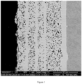
- Figure 1 shows a Scanning Electron Microscope (SEM) image of sample R6 (NiP / SiC / B4C).
- Morphological characterization of composite coatings shows the typical features of composite materials. Surface appearance, if not lapped, is dull and matt, while cross section observations show a two phases structure constituted by the NiP alloy metal matrix and the dispersion phase, i.e. SiC or mixture of SiC and B4C. A multilayer structure due to NiP and composite layer alternation is also observed.
- the NiP matrix is obtained in a high phosphorus plating electrolyte with P content in the matrix typically, 10% by weight.
- the crystalline structure evolution (XRD) with thermal treatment at various temperature between 300-500 °C for 1 hour shows the initial amorphous structure evolves into a crystalline one constituted by metallic Ni and hard NixPy intermetallic compounds.
- Table 2 reports the results of the micro-hardness measurements performed on sections of the samples described above.
- the thickness of the coatings ranging from 50-200 ⁇ m
- the morphology of the coatings has required the use of micro-indentation (100 g weight).
- Table 2 also reports the results ⁇ Surface texture' (Sa) measurements obtained by optical digital microscopy.
- Erosion tests have been performed in an experimental station composed of a mixing tank, a centrifugal pump and a test tank containing the nozzle and the sample, using a slurry prepared by mixing water and sand.
- Commercial sand was used, named "Impalpabile” from Sabbie Sataf (size ⁇ 400 ⁇ m).
- the nozzle is made of tungsten carbide with a cylindrical shape and an internal diameter of 8 mm.
- Previously weighed samples (6.9 x 7.5 x 0.4 cm) were subjected to a slurry highpressure perpendicular jet from the nozzle, for a variable duration time comprised between 2 and 5 minutes.
- the slurry is continuously circulated from the mixing tank through the centrifugal pump to the nozzle in the test tank and then back to the mixing tank.
- the nozzle is placed within the test tank at a distance of 20 mm from the surface of the sample to be tested, with the jet directed perpendicularly to the surface. Both the nozzle and the sample are completely sunk in the slurry so that no gas is entrained by the jet. After the test, each sample is washed, rinsed and weighed again.
- ER is calculated from ER measured on samples tested at 2, 3 and 5 minutes duration time respectively.
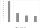
- Figure 2 reports the percentage erosion rate with respect to steel for erosion tests in experimental conditions (Test 2) reported below in order to highlight the behaviour of the coating only for composite coatings from (NiP-SiC; NiP-SiC/B4C) and commercial KEL (KEL), with total thickness of the coating 50 ⁇ m and for carbon steel for comparison:
- NiP-SiC-B4C composite coating shows an erosion resistance slightly higher than the NiP-SiC and it is able to reduce the amount of eroded material with respect to the steel substrate.
- Corrosion resistance has been evaluated through exposure tests in sour environment.
- the behaviour of the coatings (R5, R6, on steel API 5L X60 was compared with reference materials, i.e. bare API 5L X60. Corrosion was evaluated observing the formation of corrosion products after the test on Miller shaped samples.
- Tests in sour environment were performed by contact with salt solutions, hydrogen sulfide 3% and carbon dioxide 13%.
- each sample (Miller metal block 2.5 x 1.3 x 0.5 cm) is washed and sonicated in water, then degreased with aceton, dried in a nitrogen stream and weighed (0.1 mg precision) and placed on the arm in the tray.
- the applied load on standard Miller block samples was 22.24 N. Miller tests and SAR numbers were performed and calculated according to the standard for the coatings and a reference material (Steel Fe-27Cr). For the NiP coatings, a specific weight of 7,75 g/cm 3 was used.
- the low corrosion resistance featured by the steel substrate underline the importance of having an optimal adherence of the coating to the substrate. A detachment caused by accidental reasons would compromise the excellent corrosion resistance performances of the coating.
- NiP / SiC and NiP /SiC / B4C have generally regular morphology.
Landscapes
- Chemical & Material Sciences (AREA)
- General Chemical & Material Sciences (AREA)
- Chemical Kinetics & Catalysis (AREA)
- Engineering & Computer Science (AREA)
- Materials Engineering (AREA)
- Mechanical Engineering (AREA)
- Metallurgy (AREA)
- Organic Chemistry (AREA)
- Dispersion Chemistry (AREA)
- Chemically Coating (AREA)
Claims (14)
- Système comprenant un substrat et un revêtement composite anélectrolytique en contact avec le substrat, dans lequel le revêtement composite anélectrolytique comprend une structure en couches alternant une couche métallique de NiP comprenant Ni et P et une couche composite de NiP, ladite couche composite de NiP comprenant Ni, P et des particules dispersées, dans lequel les particules dispersées sont un mélange comprenant des premières et deuxièmes particules et les premières et deuxièmes particules sont de taille et de nature différentes, et dans lequel la structure en couches alternant au moins une couche métallique de NiP comprenant Ni et P ; au moins une couche composite de NiP comprenant Ni, P et des particules dispersées ; et au moins une autre couche de NiP ou couche composite de NiP.
- Système selon la revendication 1, dans lequel la couche métallique de NiP et/ou la couche composite de NiP comprend P en une quantité entre 1 et 20 % en poids par rapport au poids total de la matrice métallique dans la couche.
- Système selon la revendication 1 ou 2, dans lequel les premières particules présentent une taille moyenne entre 500 et 3 000 nm et les deuxièmes particules présentent une taille moyenne entre 50 et 500 nm.
- Système selon l'une quelconque des revendications précédentes, dans lequel les particules sont des particules de carbure de bore et/ou des nanoparticules de silicium.
- Système selon l'une quelconque des revendications précédentes, dans lequel la couche métallique de NiP est constituée de Ni et de P ou de Ni, de P et d'un ou de plusieurs éléments métalliques supplémentaires.
- Système selon l'une quelconque des revendications précédentes, dans lequel la couche composite de NiP est constituée de Ni et de P et du mélange de particules dispersées, ou de Ni, de P, du mélange de particules dispersées et d'un ou de plusieurs éléments métalliques supplémentaires.
- Système selon l'une quelconque des revendications précédentes, dans lequel l'alternance se produit de 3 à 11 fois, de préférence 5, 7 ou 9 fois.
- Système selon l'une quelconque des revendications précédentes, dans lequel la couche formée sur et en contact avec le substrat est une couche métallique de NiP.
- Système selon l'une quelconque des revendications précédentes, dans lequel la couche externe est une couche composite de NiP.
- Pipeline comprenant le système selon l'une quelconque des revendications 1 à 9
- Pipeline selon la revendication 10, dont la surface interne est revêtue.
- Utilisation du système selon l'une quelconque des revendications 1 à 9 pour améliorer la résistance d'un pipeline contre la dégradation chimique et mécanique.
- Procédé de production du système selon l'une quelconque des revendications 1 à 9 ou du pipeline selon la revendication 10 ou 11, comprenant les étapes suivantes :a) la préparation d'un substrat ;b) le dépôt d'une couche métallique de NiP, ou d'une couche composite de NiP sur le substrat,c) le dépôt d'une couche composite de NiP sur le substrat revêtu d'une couche métallique de NiP ou le dépôt d'une couche métallique de NiP sur le substrat revêtu d'une couche composite de NiP ; dans lequel l'étape c) est répétée au moins deux fois (trois couches), facultativement le procédé comprenant en outre un traitement thermique comprenant le chauffage du système après le dépôt d'au moins une couche à des températures dans la plage de 200 à 600 °C.
- Procédé selon la revendication 13, dans lequel l'étape c) est répétée autant de fois que nécessaire du moment que l'alternance couche métallique de NiP/couche composite de NiP ou couche composite de NiP/couche métallique de NiP est maintenue, de préférence est répétée jusqu'à 10 fois.
Applications Claiming Priority (2)
| Application Number | Priority Date | Filing Date | Title |
|---|---|---|---|
| IT201900012972 | 2019-07-26 | ||
| PCT/IB2020/057025 WO2021019406A1 (fr) | 2019-07-26 | 2020-07-24 | Composite nickel-phosphore multicouche |
Publications (2)
| Publication Number | Publication Date |
|---|---|
| EP4004256A1 EP4004256A1 (fr) | 2022-06-01 |
| EP4004256B1 true EP4004256B1 (fr) | 2024-01-17 |
Family
ID=68653533
Family Applications (1)
| Application Number | Title | Priority Date | Filing Date |
|---|---|---|---|
| EP20747144.2A Active EP4004256B1 (fr) | 2019-07-26 | 2020-07-24 | Composite nickel-phosphore multicouche |
Country Status (5)
| Country | Link |
|---|---|
| US (1) | US11970779B2 (fr) |
| EP (1) | EP4004256B1 (fr) |
| DK (1) | DK4004256T3 (fr) |
| PL (1) | PL4004256T3 (fr) |
| WO (1) | WO2021019406A1 (fr) |
Families Citing this family (3)
| Publication number | Priority date | Publication date | Assignee | Title |
|---|---|---|---|---|
| CN117026221B (zh) * | 2023-08-14 | 2025-11-18 | 上海交通大学 | 一种纳米氧化铝增强空心微点阵材料及其制备方法 |
| CN117286480A (zh) * | 2023-09-21 | 2023-12-26 | 大连理工大学 | 一种作为电子封装钎焊界面扩散阻挡层的Ni-Cu-P非晶合金镀层的化学镀制备工艺 |
| EP4534794A1 (fr) * | 2023-10-04 | 2025-04-09 | Sandvik Mining and Construction Tools AB | Composant de forage protégé contre l'usure et la corrosion à base de nickel |
Family Cites Families (8)
| Publication number | Priority date | Publication date | Assignee | Title |
|---|---|---|---|---|
| US4358923A (en) * | 1980-04-10 | 1982-11-16 | Surface Technology, Inc. | Composite coatings for open-end machinery parts |
| US20090011136A1 (en) | 2005-05-06 | 2009-01-08 | Thomas Steven Lancsek | Composite electroless plating |
| JP4495054B2 (ja) | 2005-09-02 | 2010-06-30 | 三菱重工業株式会社 | 回転機械の部品及び回転機械 |
| US20110016275A1 (en) | 2008-03-04 | 2011-01-20 | Nxp B.V. | Mobile communication device and method for implementing mifare memory multiple sectors mechanisms |
| CH699702A1 (de) | 2008-10-07 | 2010-04-15 | Daetwyler Swisstec Ag | Diamantbeschichtete Rakel. |
| IT1397144B1 (it) | 2009-11-30 | 2013-01-04 | Nuovo Pignone Spa | Substrato placcato non elettricamente con composto di nickel e metodo. |
| US20110162751A1 (en) | 2009-12-23 | 2011-07-07 | Exxonmobil Research And Engineering Company | Protective Coatings for Petrochemical and Chemical Industry Equipment and Devices |
| US20160010214A1 (en) | 2014-07-10 | 2016-01-14 | Macdermid Acumen, Inc. | Composite Electroless Nickel Plating |
-
2020
- 2020-07-24 PL PL20747144.2T patent/PL4004256T3/pl unknown
- 2020-07-24 US US17/630,011 patent/US11970779B2/en active Active
- 2020-07-24 EP EP20747144.2A patent/EP4004256B1/fr active Active
- 2020-07-24 DK DK20747144.2T patent/DK4004256T3/da active
- 2020-07-24 WO PCT/IB2020/057025 patent/WO2021019406A1/fr not_active Ceased
Also Published As
| Publication number | Publication date |
|---|---|
| EP4004256A1 (fr) | 2022-06-01 |
| WO2021019406A1 (fr) | 2021-02-04 |
| PL4004256T3 (pl) | 2024-06-24 |
| US11970779B2 (en) | 2024-04-30 |
| DK4004256T3 (da) | 2024-02-26 |
| US20220259742A1 (en) | 2022-08-18 |
Similar Documents
| Publication | Publication Date | Title |
|---|---|---|
| El Rayes et al. | Erosion-corrosion of cermet coating | |
| Luo et al. | Synthesis of a duplex Ni-P-YSZ/Ni-P nanocomposite coating and investigation of its performance | |
| TWI674332B (zh) | 於基材上產生金屬-陶瓷覆層之鍍覆或塗覆方法 | |
| Maharana et al. | Structure dependent super-hydrophobic and corrosion resistant behavior of electrodeposited Ni-MoSe2-MWCNT coating | |
| KR20240093443A (ko) | 코팅된 표면, 코팅 및 이를 사용하는 물품을 생성하는 공정 | |
| US11970779B2 (en) | Multilayered nickel-phosphorus composite | |
| EP2374916A1 (fr) | Système de revêtement résistant à l'érosion et à la corrosion pour compresseur | |
| Farhan et al. | Synthesis and properties of electroless Ni–P-HfC nanocomposite coatings | |
| Yang et al. | Microstructure and corrosion behavior of electroless Ni–P on sprayed Al–Ce coating of 3003 aluminum alloy | |
| Wang et al. | High corrosion and wear resistant electroless Ni-P gradient coatings on aviation aluminum alloy parts | |
| Farhan et al. | Mechanical and corrosion characteristics of TiC reinforced Ni-P based nanocomposite coatings | |
| Hyie et al. | Effect of deposition time on wear and corrosion performance of Co–Ni–Fe alloy coated mild steel | |
| Julka et al. | Effect of pH on mechanical, physical and tribological properties of electroless Ni-P-Al2O3 composite deposits for marine applications | |
| Shi et al. | Preparation of electroplated Ni-P-ultrafine diamond, Ni-P-carbon nanotubes composite coatings and their corrosion properties | |
| Liu et al. | Study on corrosion resistance and tribo behavior of electrodeposited Ni–W–P/TiN composite coatings | |
| Murugesan et al. | Extending the lifetime of oil and gas equipment with corrosion and erosion-resistant Ni-B-nanodiamond metal-matrix-nanocomposite coatings | |
| KR20120101476A (ko) | 무전해 니켈-복합물 도금된 기판 및 제조 방법 | |
| Fayomi et al. | Structural and properties of Zn-Al2O3-SiC nano-composite coatings by direct electrolytic process | |
| Srinivasan et al. | Studies on electroless nickel–PTFE composite coatings | |
| Ünal et al. | Investigation of the Properties of Ni-B Alloy Nanocomposite Coatings Reinforced with TiC Particles Electrodeposited at Different Current Densities | |
| Arroyo et al. | Structural modification of electrodeposited nickel coatings by ceramic particles incorporation to enhance corrosion-erosion resistance | |
| Abdel Hamid et al. | Electrodeposition and characterization of chromium–tungsten carbide composite coatings from a trivalent chromium bath | |
| Mindivan et al. | The study of electroless Ni-P/Ni-B duplex coating on HVOF-sprayed martensitic stainless steel coating | |
| Zhang et al. | Electrodeposition of multi-layer Pd–Ni coatings on 316L stainless steel and their corrosion resistance in hot sulfuric acid solution | |
| Zhang et al. | Study of the corrosion resistance of a superhydrophobic Ni-P-Al2O3 composite coating based on electrochemical machining |
Legal Events
| Date | Code | Title | Description |
|---|---|---|---|
| STAA | Information on the status of an ep patent application or granted ep patent |
Free format text: STATUS: UNKNOWN |
|
| STAA | Information on the status of an ep patent application or granted ep patent |
Free format text: STATUS: THE INTERNATIONAL PUBLICATION HAS BEEN MADE |
|
| PUAI | Public reference made under article 153(3) epc to a published international application that has entered the european phase |
Free format text: ORIGINAL CODE: 0009012 |
|
| STAA | Information on the status of an ep patent application or granted ep patent |
Free format text: STATUS: REQUEST FOR EXAMINATION WAS MADE |
|
| 17P | Request for examination filed |
Effective date: 20220202 |
|
| AK | Designated contracting states |
Kind code of ref document: A1 Designated state(s): AL AT BE BG CH CY CZ DE DK EE ES FI FR GB GR HR HU IE IS IT LI LT LU LV MC MK MT NL NO PL PT RO RS SE SI SK SM TR |
|
| DAV | Request for validation of the european patent (deleted) | ||
| DAX | Request for extension of the european patent (deleted) | ||
| STAA | Information on the status of an ep patent application or granted ep patent |
Free format text: STATUS: EXAMINATION IS IN PROGRESS |
|
| 17Q | First examination report despatched |
Effective date: 20230221 |
|
| GRAP | Despatch of communication of intention to grant a patent |
Free format text: ORIGINAL CODE: EPIDOSNIGR1 |
|
| STAA | Information on the status of an ep patent application or granted ep patent |
Free format text: STATUS: GRANT OF PATENT IS INTENDED |
|
| INTG | Intention to grant announced |
Effective date: 20230816 |
|
| GRAS | Grant fee paid |
Free format text: ORIGINAL CODE: EPIDOSNIGR3 |
|
| GRAA | (expected) grant |
Free format text: ORIGINAL CODE: 0009210 |
|
| STAA | Information on the status of an ep patent application or granted ep patent |
Free format text: STATUS: THE PATENT HAS BEEN GRANTED |
|
| P01 | Opt-out of the competence of the unified patent court (upc) registered |
Effective date: 20231206 |
|
| AK | Designated contracting states |
Kind code of ref document: B1 Designated state(s): AL AT BE BG CH CY CZ DE DK EE ES FI FR GB GR HR HU IE IS IT LI LT LU LV MC MK MT NL NO PL PT RO RS SE SI SK SM TR |
|
| REG | Reference to a national code |
Ref country code: GB Ref legal event code: FG4D |
|
| REG | Reference to a national code |
Ref country code: DE Ref legal event code: R096 Ref document number: 602020024525 Country of ref document: DE |
|
| REG | Reference to a national code |
Ref country code: CH Ref legal event code: EP |
|
| REG | Reference to a national code |
Ref country code: IE Ref legal event code: FG4D |
|
| REG | Reference to a national code |
Ref country code: DK Ref legal event code: T3 Effective date: 20240221 |
|
| REG | Reference to a national code |
Ref country code: NL Ref legal event code: FP |
|
| REG | Reference to a national code |
Ref country code: LT Ref legal event code: MG9D |
|
| REG | Reference to a national code |
Ref country code: AT Ref legal event code: MK05 Ref document number: 1650571 Country of ref document: AT Kind code of ref document: T Effective date: 20240117 |
|
| PG25 | Lapsed in a contracting state [announced via postgrant information from national office to epo] |
Ref country code: IS Free format text: LAPSE BECAUSE OF FAILURE TO SUBMIT A TRANSLATION OF THE DESCRIPTION OR TO PAY THE FEE WITHIN THE PRESCRIBED TIME-LIMIT Effective date: 20240517 |
|
| PG25 | Lapsed in a contracting state [announced via postgrant information from national office to epo] |
Ref country code: LT Free format text: LAPSE BECAUSE OF FAILURE TO SUBMIT A TRANSLATION OF THE DESCRIPTION OR TO PAY THE FEE WITHIN THE PRESCRIBED TIME-LIMIT Effective date: 20240117 |
|
| PG25 | Lapsed in a contracting state [announced via postgrant information from national office to epo] |
Ref country code: GR Free format text: LAPSE BECAUSE OF FAILURE TO SUBMIT A TRANSLATION OF THE DESCRIPTION OR TO PAY THE FEE WITHIN THE PRESCRIBED TIME-LIMIT Effective date: 20240418 |
|
| PG25 | Lapsed in a contracting state [announced via postgrant information from national office to epo] |
Ref country code: HR Free format text: LAPSE BECAUSE OF FAILURE TO SUBMIT A TRANSLATION OF THE DESCRIPTION OR TO PAY THE FEE WITHIN THE PRESCRIBED TIME-LIMIT Effective date: 20240117 Ref country code: RS Free format text: LAPSE BECAUSE OF FAILURE TO SUBMIT A TRANSLATION OF THE DESCRIPTION OR TO PAY THE FEE WITHIN THE PRESCRIBED TIME-LIMIT Effective date: 20240417 |
|
| PG25 | Lapsed in a contracting state [announced via postgrant information from national office to epo] |
Ref country code: ES Free format text: LAPSE BECAUSE OF FAILURE TO SUBMIT A TRANSLATION OF THE DESCRIPTION OR TO PAY THE FEE WITHIN THE PRESCRIBED TIME-LIMIT Effective date: 20240117 |
|
| PG25 | Lapsed in a contracting state [announced via postgrant information from national office to epo] |
Ref country code: AT Free format text: LAPSE BECAUSE OF FAILURE TO SUBMIT A TRANSLATION OF THE DESCRIPTION OR TO PAY THE FEE WITHIN THE PRESCRIBED TIME-LIMIT Effective date: 20240117 |
|
| PG25 | Lapsed in a contracting state [announced via postgrant information from national office to epo] |
Ref country code: RS Free format text: LAPSE BECAUSE OF FAILURE TO SUBMIT A TRANSLATION OF THE DESCRIPTION OR TO PAY THE FEE WITHIN THE PRESCRIBED TIME-LIMIT Effective date: 20240417 Ref country code: LT Free format text: LAPSE BECAUSE OF FAILURE TO SUBMIT A TRANSLATION OF THE DESCRIPTION OR TO PAY THE FEE WITHIN THE PRESCRIBED TIME-LIMIT Effective date: 20240117 Ref country code: IS Free format text: LAPSE BECAUSE OF FAILURE TO SUBMIT A TRANSLATION OF THE DESCRIPTION OR TO PAY THE FEE WITHIN THE PRESCRIBED TIME-LIMIT Effective date: 20240517 Ref country code: HR Free format text: LAPSE BECAUSE OF FAILURE TO SUBMIT A TRANSLATION OF THE DESCRIPTION OR TO PAY THE FEE WITHIN THE PRESCRIBED TIME-LIMIT Effective date: 20240117 Ref country code: GR Free format text: LAPSE BECAUSE OF FAILURE TO SUBMIT A TRANSLATION OF THE DESCRIPTION OR TO PAY THE FEE WITHIN THE PRESCRIBED TIME-LIMIT Effective date: 20240418 Ref country code: FI Free format text: LAPSE BECAUSE OF FAILURE TO SUBMIT A TRANSLATION OF THE DESCRIPTION OR TO PAY THE FEE WITHIN THE PRESCRIBED TIME-LIMIT Effective date: 20240117 Ref country code: ES Free format text: LAPSE BECAUSE OF FAILURE TO SUBMIT A TRANSLATION OF THE DESCRIPTION OR TO PAY THE FEE WITHIN THE PRESCRIBED TIME-LIMIT Effective date: 20240117 Ref country code: BG Free format text: LAPSE BECAUSE OF FAILURE TO SUBMIT A TRANSLATION OF THE DESCRIPTION OR TO PAY THE FEE WITHIN THE PRESCRIBED TIME-LIMIT Effective date: 20240117 Ref country code: AT Free format text: LAPSE BECAUSE OF FAILURE TO SUBMIT A TRANSLATION OF THE DESCRIPTION OR TO PAY THE FEE WITHIN THE PRESCRIBED TIME-LIMIT Effective date: 20240117 |
|
| PG25 | Lapsed in a contracting state [announced via postgrant information from national office to epo] |
Ref country code: PT Free format text: LAPSE BECAUSE OF FAILURE TO SUBMIT A TRANSLATION OF THE DESCRIPTION OR TO PAY THE FEE WITHIN THE PRESCRIBED TIME-LIMIT Effective date: 20240517 |
|
| PG25 | Lapsed in a contracting state [announced via postgrant information from national office to epo] |
Ref country code: SE Free format text: LAPSE BECAUSE OF FAILURE TO SUBMIT A TRANSLATION OF THE DESCRIPTION OR TO PAY THE FEE WITHIN THE PRESCRIBED TIME-LIMIT Effective date: 20240117 Ref country code: PT Free format text: LAPSE BECAUSE OF FAILURE TO SUBMIT A TRANSLATION OF THE DESCRIPTION OR TO PAY THE FEE WITHIN THE PRESCRIBED TIME-LIMIT Effective date: 20240517 Ref country code: LV Free format text: LAPSE BECAUSE OF FAILURE TO SUBMIT A TRANSLATION OF THE DESCRIPTION OR TO PAY THE FEE WITHIN THE PRESCRIBED TIME-LIMIT Effective date: 20240117 |
|
| PG25 | Lapsed in a contracting state [announced via postgrant information from national office to epo] |
Ref country code: SM Free format text: LAPSE BECAUSE OF FAILURE TO SUBMIT A TRANSLATION OF THE DESCRIPTION OR TO PAY THE FEE WITHIN THE PRESCRIBED TIME-LIMIT Effective date: 20240117 |
|
| REG | Reference to a national code |
Ref country code: DE Ref legal event code: R097 Ref document number: 602020024525 Country of ref document: DE |
|
| PG25 | Lapsed in a contracting state [announced via postgrant information from national office to epo] |
Ref country code: CZ Free format text: LAPSE BECAUSE OF FAILURE TO SUBMIT A TRANSLATION OF THE DESCRIPTION OR TO PAY THE FEE WITHIN THE PRESCRIBED TIME-LIMIT Effective date: 20240117 Ref country code: EE Free format text: LAPSE BECAUSE OF FAILURE TO SUBMIT A TRANSLATION OF THE DESCRIPTION OR TO PAY THE FEE WITHIN THE PRESCRIBED TIME-LIMIT Effective date: 20240117 |
|
| PG25 | Lapsed in a contracting state [announced via postgrant information from national office to epo] |
Ref country code: SK Free format text: LAPSE BECAUSE OF FAILURE TO SUBMIT A TRANSLATION OF THE DESCRIPTION OR TO PAY THE FEE WITHIN THE PRESCRIBED TIME-LIMIT Effective date: 20240117 |
|
| PG25 | Lapsed in a contracting state [announced via postgrant information from national office to epo] |
Ref country code: SM Free format text: LAPSE BECAUSE OF FAILURE TO SUBMIT A TRANSLATION OF THE DESCRIPTION OR TO PAY THE FEE WITHIN THE PRESCRIBED TIME-LIMIT Effective date: 20240117 Ref country code: SK Free format text: LAPSE BECAUSE OF FAILURE TO SUBMIT A TRANSLATION OF THE DESCRIPTION OR TO PAY THE FEE WITHIN THE PRESCRIBED TIME-LIMIT Effective date: 20240117 Ref country code: EE Free format text: LAPSE BECAUSE OF FAILURE TO SUBMIT A TRANSLATION OF THE DESCRIPTION OR TO PAY THE FEE WITHIN THE PRESCRIBED TIME-LIMIT Effective date: 20240117 Ref country code: CZ Free format text: LAPSE BECAUSE OF FAILURE TO SUBMIT A TRANSLATION OF THE DESCRIPTION OR TO PAY THE FEE WITHIN THE PRESCRIBED TIME-LIMIT Effective date: 20240117 |
|
| PLBE | No opposition filed within time limit |
Free format text: ORIGINAL CODE: 0009261 |
|
| STAA | Information on the status of an ep patent application or granted ep patent |
Free format text: STATUS: NO OPPOSITION FILED WITHIN TIME LIMIT |
|
| 26N | No opposition filed |
Effective date: 20241018 |
|
| PG25 | Lapsed in a contracting state [announced via postgrant information from national office to epo] |
Ref country code: MC Free format text: LAPSE BECAUSE OF FAILURE TO SUBMIT A TRANSLATION OF THE DESCRIPTION OR TO PAY THE FEE WITHIN THE PRESCRIBED TIME-LIMIT Effective date: 20240117 |
|
| REG | Reference to a national code |
Ref country code: CH Ref legal event code: PL |
|
| PG25 | Lapsed in a contracting state [announced via postgrant information from national office to epo] |
Ref country code: LU Free format text: LAPSE BECAUSE OF NON-PAYMENT OF DUE FEES Effective date: 20240724 |
|
| PG25 | Lapsed in a contracting state [announced via postgrant information from national office to epo] |
Ref country code: LU Free format text: LAPSE BECAUSE OF NON-PAYMENT OF DUE FEES Effective date: 20240724 |
|
| PG25 | Lapsed in a contracting state [announced via postgrant information from national office to epo] |
Ref country code: SI Free format text: LAPSE BECAUSE OF FAILURE TO SUBMIT A TRANSLATION OF THE DESCRIPTION OR TO PAY THE FEE WITHIN THE PRESCRIBED TIME-LIMIT Effective date: 20240117 Ref country code: CH Free format text: LAPSE BECAUSE OF NON-PAYMENT OF DUE FEES Effective date: 20240731 Ref country code: BE Free format text: LAPSE BECAUSE OF NON-PAYMENT OF DUE FEES Effective date: 20240731 |
|
| PG25 | Lapsed in a contracting state [announced via postgrant information from national office to epo] |
Ref country code: FR Free format text: LAPSE BECAUSE OF NON-PAYMENT OF DUE FEES Effective date: 20240731 |
|
| REG | Reference to a national code |
Ref country code: BE Ref legal event code: MM Effective date: 20240731 |
|
| PG25 | Lapsed in a contracting state [announced via postgrant information from national office to epo] |
Ref country code: IE Free format text: LAPSE BECAUSE OF NON-PAYMENT OF DUE FEES Effective date: 20240724 |
|
| PGFP | Annual fee paid to national office [announced via postgrant information from national office to epo] |
Ref country code: NL Payment date: 20250726 Year of fee payment: 6 |
|
| PGFP | Annual fee paid to national office [announced via postgrant information from national office to epo] |
Ref country code: DE Payment date: 20250729 Year of fee payment: 6 Ref country code: DK Payment date: 20250725 Year of fee payment: 6 |
|
| PGFP | Annual fee paid to national office [announced via postgrant information from national office to epo] |
Ref country code: NO Payment date: 20250729 Year of fee payment: 6 |
|
| PGFP | Annual fee paid to national office [announced via postgrant information from national office to epo] |
Ref country code: PL Payment date: 20250701 Year of fee payment: 6 Ref country code: TR Payment date: 20250711 Year of fee payment: 6 Ref country code: IT Payment date: 20250721 Year of fee payment: 6 |
|
| PGFP | Annual fee paid to national office [announced via postgrant information from national office to epo] |
Ref country code: GB Payment date: 20250728 Year of fee payment: 6 |
|
| PGFP | Annual fee paid to national office [announced via postgrant information from national office to epo] |
Ref country code: RO Payment date: 20250707 Year of fee payment: 6 |
|
| PGFP | Annual fee paid to national office [announced via postgrant information from national office to epo] |
Ref country code: CY Payment date: 20250703 Year of fee payment: 6 |
|
| PG25 | Lapsed in a contracting state [announced via postgrant information from national office to epo] |
Ref country code: HU Free format text: LAPSE BECAUSE OF FAILURE TO SUBMIT A TRANSLATION OF THE DESCRIPTION OR TO PAY THE FEE WITHIN THE PRESCRIBED TIME-LIMIT; INVALID AB INITIO Effective date: 20200724 |