EP4004287B1 - Unité de soudage pour le soudage de rails d'une voie - Google Patents
Unité de soudage pour le soudage de rails d'une voie Download PDFInfo
- Publication number
- EP4004287B1 EP4004287B1 EP20735558.7A EP20735558A EP4004287B1 EP 4004287 B1 EP4004287 B1 EP 4004287B1 EP 20735558 A EP20735558 A EP 20735558A EP 4004287 B1 EP4004287 B1 EP 4004287B1
- Authority
- EP
- European Patent Office
- Prior art keywords
- unit
- welding
- sub
- clamping
- cylinders
- Prior art date
- Legal status (The legal status is an assumption and is not a legal conclusion. Google has not performed a legal analysis and makes no representation as to the accuracy of the status listed.)
- Active
Links
Images
Classifications
-
- E—FIXED CONSTRUCTIONS
- E01—CONSTRUCTION OF ROADS, RAILWAYS, OR BRIDGES
- E01B—PERMANENT WAY; PERMANENT-WAY TOOLS; MACHINES FOR MAKING RAILWAYS OF ALL KINDS
- E01B11/00—Rail joints
- E01B11/44—Non-dismountable rail joints; Welded joints
- E01B11/46—General methods for making gapless tracks
-
- E—FIXED CONSTRUCTIONS
- E01—CONSTRUCTION OF ROADS, RAILWAYS, OR BRIDGES
- E01B—PERMANENT WAY; PERMANENT-WAY TOOLS; MACHINES FOR MAKING RAILWAYS OF ALL KINDS
- E01B29/00—Laying, rebuilding, or taking-up tracks; Tools or machines therefor
- E01B29/42—Undetachably joining or fastening track components in or on the track, e.g. by welding, by gluing; Pre-assembling track components by gluing; Sealing joints with filling components
- E01B29/46—Devices for holding, positioning, or urging together the rail ends
-
- B—PERFORMING OPERATIONS; TRANSPORTING
- B23—MACHINE TOOLS; METAL-WORKING NOT OTHERWISE PROVIDED FOR
- B23K—SOLDERING OR UNSOLDERING; WELDING; CLADDING OR PLATING BY SOLDERING OR WELDING; CUTTING BY APPLYING HEAT LOCALLY, e.g. FLAME CUTTING; WORKING BY LASER BEAM
- B23K11/00—Resistance welding; Severing by resistance heating
- B23K11/04—Flash butt welding
- B23K11/046—Apparatus therefor
-
- B—PERFORMING OPERATIONS; TRANSPORTING
- B23—MACHINE TOOLS; METAL-WORKING NOT OTHERWISE PROVIDED FOR
- B23K—SOLDERING OR UNSOLDERING; WELDING; CLADDING OR PLATING BY SOLDERING OR WELDING; CUTTING BY APPLYING HEAT LOCALLY, e.g. FLAME CUTTING; WORKING BY LASER BEAM
- B23K37/00—Auxiliary devices or processes, not specially adapted for a procedure covered by only one of the other main groups of this subclass
- B23K37/02—Carriages for supporting the welding or cutting element
- B23K37/0211—Carriages for supporting the welding or cutting element travelling on a guide member, e.g. rail, track
- B23K37/0217—Carriages for supporting the welding or cutting element travelling on a guide member, e.g. rail, track the guide member being fixed to the workpiece
-
- B—PERFORMING OPERATIONS; TRANSPORTING
- B23—MACHINE TOOLS; METAL-WORKING NOT OTHERWISE PROVIDED FOR
- B23K—SOLDERING OR UNSOLDERING; WELDING; CLADDING OR PLATING BY SOLDERING OR WELDING; CUTTING BY APPLYING HEAT LOCALLY, e.g. FLAME CUTTING; WORKING BY LASER BEAM
- B23K37/00—Auxiliary devices or processes, not specially adapted for a procedure covered by only one of the other main groups of this subclass
- B23K37/02—Carriages for supporting the welding or cutting element
- B23K37/0282—Carriages forming part of a welding unit
-
- B—PERFORMING OPERATIONS; TRANSPORTING
- B23—MACHINE TOOLS; METAL-WORKING NOT OTHERWISE PROVIDED FOR
- B23K—SOLDERING OR UNSOLDERING; WELDING; CLADDING OR PLATING BY SOLDERING OR WELDING; CUTTING BY APPLYING HEAT LOCALLY, e.g. FLAME CUTTING; WORKING BY LASER BEAM
- B23K2101/00—Articles made by soldering, welding or cutting
- B23K2101/26—Railway- or like rails
Definitions
- the invention relates to a welding unit for welding rails of a track, with a first unit part which can be displaced on unit guides relative to a second unit part by means of displacement cylinders in a rail longitudinal direction, each unit part comprising clamping cylinders coupled with clamping jaws below the unit guides for clamping the rails.
- Known welding units for welding rails have two unit parts, one unit part being displaceable on unit guides by means of displacement cylinders in a rail longitudinal direction relative to the other unit part.
- the respective unit part includes a clamping device for clamping a rail end of the rails to be welded. During the welding process, the unit parts and the rail ends clamped in them are moved towards one another.
- Generic welding units are also used for final welds below a normal temperature.
- the rail ends have to be subjected to high tensile forces.
- the demands on the unit guides, the shifting cylinders and the clamping devices are correspondingly high.
- each assembly part comprises two pincer levers which can be pivoted about an axis of rotation aligned in the longitudinal direction of the rail.
- Clamping jaws for clamping the rail ends are arranged on the lower lever arms.
- Upper lever arms are coupled to a clamping cylinder.
- the shifting cylinders are arranged on both sides of the rails to be welded.
- the displacement cylinders also serve as unit guides with a guide column arranged in the axis of rotation.
- the tong-shaped design of the unit parts means that the clamping cylinders are arranged above the unit guides and that clamping forces stress the bearings of the unit parts on the guide column.
- a respective assembly part comprises a rigid base body, which has a free space on its underside for a rail end to be clamped.
- Clamping jaws are coupled directly to clamping cylinders arranged below the unit guides.
- loading the clamping cylinders directly causes a clamping force, with the base body absorbing the opposing forces. Shifting of one unit part in relation to the other unit part takes place via tie rods and displacement cylinders, which are supported in relation to the cross member.
- the invention is based on the object of specifying a welding unit of the type mentioned at the outset with an improved structure.
- the two unit parts are connected by means of the displacement cylinders, in that a cylinder body of the respective displacement cylinder is connected to one unit part and a piston rod of the respective displacement cylinder is connected to the other unit part.
- the shifting cylinders together with the clamping cylinders form a unit for the transmission of longitudinal forces into the rail ends to be welded.
- Essential here is the functional decoupling of the unit guides from the power transmission.
- the unit guides take on the guiding function of the two unit parts relative to one another without making a contribution to the clamping function of the clamping cylinder.
- the unit guides remain free of tensile or compressive forces.
- the longitudinal axes of the displacement cylinders and the longitudinal axes of the clamping cylinders are arranged approximately in a common plane. This minimizes the stresses in the unit parts because no additional bending stresses occur as a result of spaced force axes.
- the clamping jaws are arranged in such a way that the rails to be welded can be clamped with a neutral axis lying in the common plane. In this way, the displacement forces act in one plane with the neutral axis of the rails, so that the unit parts and the unit guides do not have to absorb any tilting moments. Only the weight of the unit parts and the rail ends that are clamped and raised during a welding process act on the unit guides.
- each unit part includes a clamping body below the unit guides, in which several clamping cylinders are integrated next to one another. A compact construction of the respective unit part is thus achieved, with a sufficiently high resulting total clamping force being available.
- a compact design of the entire welding unit is favored if the displacement cylinders are flanged to the lateral outer surfaces of the unit parts. In this way, the arrangement of the shifting cylinders is structurally decoupled from the unit parts and the clamping cylinders. This simplifies the design of the welding unit, the displacement forces that can be achieved being variable by arranging different displacement cylinders. The result is a modular system in which identical unit parts can be used for welding units with different outputs.
- the guide system consists of three, in particular designed as sliding tubes Aggregate guides are offset from one another. In this way an optimum between weight and stability of the guide system can be achieved.
- Two outer unit guides are advantageously arranged next to one another and a central unit guide is arranged offset upwards.
- the forces to be absorbed are distributed largely evenly over the three unit guides.
- the stability of the guide system is further increased if the first unit part is arranged between the second unit part and a cross-connection part and if the unit guides are rigidly connected to the second unit part on the one hand and rigidly to the cross-connection part on the other.
- the cross-connection part is only a component of the guide system and does not transfer any displacement or clamping forces.
- each unit part includes an identical base body. This advantageous embodiment is achieved by decoupling the guide system and the displacement cylinder.
- the respective base body has a plurality of connection points for flanging on displacement cylinders of different lengths next to one another on both longitudinal sides. In this way, the attachment of the displacement cylinder can be easily varied. Welding units with different outputs can be realized by exchanging the shifting cylinders.
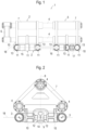
- a first unit part 2 can be displaced by means of displacement cylinders 3 along unit guides 4 in relation to a second unit part 5 .
- the unit guides 4 arranged in the cross section at the corner points of an isosceles triangle are rigidly connected to a cross-connection part 6 at the end.
- the unit guides 4 are rigidly connected to the second unit part 5 on the opposite side of the cross-connection part 6 .
- the displaceable first unit part 2 is arranged in between. In this way, the unit guides 4 form a rigid guide system with the end connections.
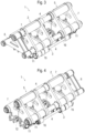
- Each assembly part 2, 5 includes an identical base body 7, which is designed, for example, as a welded construction.
- the unit guides 4 include three sliding tubes. Two lower slide tubes are arranged symmetrically with respect to a vertical surface 8 of symmetry. An upper sliding tube is arranged centrally above it, so that the longitudinal axis of the sliding tube lies in the plane of symmetry 8 .
- each unit part 2, 5 comprises a respective clamping body 10 on both sides of a free space 9.
- the respective clamping body 10 three inner cylinders are arranged side by side, in which pistons with piston rods are guided.
- each clamping body 10 comprises three hydraulically coupled clamping cylinders 11, the piston rods of which are connected at the end to a common clamping jaw 12.
- the clamping cylinders 11 are closed by means of cylinder covers 13 on the outer surfaces of the respective clamping body 10 .
- Rails 14 to be welded are accommodated and clamped in the free space 9 between the clamping bodies 10 .
- the clamping cylinders 11 are hydraulically loaded, as a result of which the clamping jaws 12 are pressed against the rails 14 to be welded to one another.
- the displacement cylinders 3 are flanged on both sides to the lateral outer surfaces of the unit parts 2, 5.
- a cylinder body 15 of the respective displacement cylinder 3 is connected to one unit part 2 and a piston rod 16 is connected to the other unit part 5 .
- Connection points 17 for the displacement cylinders 3 are advantageously arranged in the area between two clamping cylinders 11 of the respective clamping body 10 . In this way, the longitudinal axes of the displacement cylinders 3 and the longitudinal axes of the clamping cylinders 11 are arranged approximately in a common plane 18 . The aim is to avoid bending moments caused by vertically spaced force axes.
- each clamping body 10 has two connecting points 17 between the three clamping cylinders 11 .
- longer displacement cylinders 3 with a plurality of pressure chambers can then be flanged onto the connection points 17 that are furthest apart from one another.
- a shearing device for removing a welding bead is provided between the two unit parts 2, 5.
- a lifting device for lifting the rails is attached to each outer face of the two unit parts 2, 5.
- both rails 14 are lifted off the underlying sleepers by the lifting devices and pressed against stop elements.
- the clamping cylinders 11 are then acted upon in order to press the clamping jaws against a rail web of the respective rail 14 with a high clamping force (eg 1600 kN).
- the clamping jaws 12 are connected to a secondary circuit of the welding unit 1 and cause current to be transmitted to the rails 14.
- separate electrical electrodes can also be pressed onto the rails 14.
- the unit parts 2, 5 together with the gripped rails 14 are moved towards one another by applying a tensile force to the displacement drives 3. With a so-called final weld, up to 1500 kN can be achieved. As soon as the distance between the two rail ends required for welding is reached, the power supply is initiated.
Landscapes
- Engineering & Computer Science (AREA)
- Mechanical Engineering (AREA)
- Architecture (AREA)
- Civil Engineering (AREA)
- Structural Engineering (AREA)
- Physics & Mathematics (AREA)
- Optics & Photonics (AREA)
- Machines For Laying And Maintaining Railways (AREA)
- Butt Welding And Welding Of Specific Article (AREA)
Claims (10)
- Module de soudure (1) pour la soudure de rails (14) d'une voie ferrée, avec une première partie de module (2) qui peut être coulissée sur des guides de module (4) en face d'une seconde partie de module (5) au moyen de cylindres de coulissement (3) dans une direction longitudinale de rail, dans lequel chaque partie de module (2, 5) comprend des cylindres de serrage (11) couplés à des mâchoires de serrage (12) en dessous des guides de module (4) pour le serrage des rails (14), caractérisé en ce que les deux parties de module (2, 5) sont connectées au moyen des cylindres de coulissement (3) en ce qu'un corps de cylindre (15) du cylindre de coulissement respectif (3) est connecté à la partie de module en question (2 ou 5) et une tige de piston (16) du cylindre de coulissement respectif (3) est connectée à l'autre partie de module (5 ou 2).
- Module de soudure (1) selon la revendication 1, caractérisé en ce que des axes longitudinaux des cylindres de coulissement (3) et des axes longitudinaux des cylindres de serrage (11) sont disposés approximativement dans un plan commun (18).
- Module de soudure (1) selon la revendication 2, caractérisé en ce que les mâchoires de serrage (12) sont disposées de telle sorte que les rails à souder (14) peuvent être bloqués avec un axe neutre situé dans le plan commun (18).
- Module de soudure (1) selon une des revendications 1 à 3, caractérisé en ce que chaque partie de module (2, 5) comprend un corps de serrage (10) en dessous des guides de module (4) dans lequel plusieurs cylindres de serrage (11) sont intégrés côte à côte.
- Module de soudure (1) selon une des revendications 1 à 4, caractérisé en ce que les cylindres de coulissement (3) sont bridés à des faces externes latérales des parties de module (2, 5).
- Module de soudure (1) selon une des revendications 1 à 5, caractérisé en ce que trois guides de module (4) réalisés notamment en tant que tubes coulissants sont disposés de manière décalée l'un par rapport à l'autre.
- Module de soudure (1) selon la revendication 6, caractérisé en ce que deux guides de module extérieurs (4) sont disposés côte à côte et qu'un guide de module central (4) est disposé de manière décalée vers le haut.
- Module de soudure (1) selon une des revendications 1 à 7, caractérisé en ce que la première partie de module (2) est disposée entre la seconde partie de module (5) et une partie de connexion transversale (6), et que les guides de module (4) sont connectés d'un côté de manière fixe à la seconde partie de module (5) et de l'autre côté de manière fixe à la partie de connexion transversale (6).
- Module de soudure (1) selon une des revendications 1 à 8, caractérisé en ce que chaque partie de module (2, 5) comprend un corps de base identique (7).
- Module de soudure (1) selon la revendication 9, caractérisé en ce que le corps de base respectif (7) présente sur les deux côtés longitudinaux plusieurs points de connexion (17) côte à côte pour le bridage de cylindres de coulissement (3) de longueur différente.
Applications Claiming Priority (2)
| Application Number | Priority Date | Filing Date | Title |
|---|---|---|---|
| ATA265/2019A AT522860B1 (de) | 2019-07-31 | 2019-07-31 | Schweißaggregat zum Verschweißen von Schienen eines Gleises |
| PCT/EP2020/068321 WO2021018497A1 (fr) | 2019-07-31 | 2020-06-30 | Groupe de soudage destiné au soudage de rails d'une voie |
Publications (3)
| Publication Number | Publication Date |
|---|---|
| EP4004287A1 EP4004287A1 (fr) | 2022-06-01 |
| EP4004287B1 true EP4004287B1 (fr) | 2023-06-21 |
| EP4004287C0 EP4004287C0 (fr) | 2023-06-21 |
Family
ID=71409413
Family Applications (1)
| Application Number | Title | Priority Date | Filing Date |
|---|---|---|---|
| EP20735558.7A Active EP4004287B1 (fr) | 2019-07-31 | 2020-06-30 | Unité de soudage pour le soudage de rails d'une voie |
Country Status (13)
| Country | Link |
|---|---|
| US (1) | US12281448B2 (fr) |
| EP (1) | EP4004287B1 (fr) |
| JP (1) | JP7581324B2 (fr) |
| KR (1) | KR20220038292A (fr) |
| CN (1) | CN114173979A (fr) |
| AT (1) | AT522860B1 (fr) |
| AU (1) | AU2020322628B2 (fr) |
| CA (1) | CA3143281A1 (fr) |
| ES (1) | ES2956458T3 (fr) |
| MX (1) | MX2022000986A (fr) |
| PL (1) | PL4004287T3 (fr) |
| UA (1) | UA126784C2 (fr) |
| WO (1) | WO2021018497A1 (fr) |
Families Citing this family (1)
| Publication number | Priority date | Publication date | Assignee | Title |
|---|---|---|---|---|
| EP4100179B1 (fr) * | 2020-02-03 | 2024-04-03 | Danieli & C. Officine Meccaniche S.p.A. | Machine à souder |
Citations (1)
| Publication number | Priority date | Publication date | Assignee | Title |
|---|---|---|---|---|
| AT14053U1 (de) * | 2013-08-02 | 2015-03-15 | Plasser & Theurer Export Von Bahnbaumaschinen Gmbh | Schweissaggregat zum Verschweissen von Schienen eines Gleises |
Family Cites Families (24)
| Publication number | Priority date | Publication date | Assignee | Title |
|---|---|---|---|---|
| GB1056812A (en) * | 1964-01-17 | 1967-02-01 | Inst Elektroswarki Patona | Resistance flash butt-welding machine |
| AU517045B2 (en) * | 1977-07-08 | 1981-07-02 | C. Delachaux SA | Aligning and setting gap between rails |
| US4175897A (en) | 1978-01-05 | 1979-11-27 | Golomovzjuk Ivan K | Apparatus for removing flash from resistance butt-weld joints in rails |
| JPS63238984A (ja) * | 1986-03-05 | 1988-10-05 | Nkk Corp | レ−ル圧接のためのレ−ルのクランプ方法とそれに用いるクランプ装置 |
| AT394960B (de) * | 1990-06-15 | 1992-08-10 | Plasser Bahnbaumasch Franz | Mobiles abbrennstumpf-schweissaggregat |
| SE9504368D0 (sv) * | 1995-12-05 | 1995-12-05 | Esab Ab | Hopsvetsningsanordning |
| DE19735195C1 (de) | 1997-08-14 | 1999-01-21 | Bosch Gmbh Robert | Schweißvorrichtung |
| AT6690U3 (de) | 2003-11-06 | 2004-11-25 | Plasser Bahnbaumasch Franz | Verfahren zum verschweissen von schienen eines gleises |
| AT507243B1 (de) | 2008-08-04 | 2010-06-15 | Plasser Bahnbaumasch Franz | Schweissaggregat zum verschweissen von schienen eines gleises |
| AT507560B1 (de) | 2008-12-03 | 2010-06-15 | Plasser Bahnbaumasch Franz | Schweissaggregat zum verschweissen von schienen |
| US9168608B2 (en) * | 2009-04-16 | 2015-10-27 | Davide Vaia | Welding head for rail welding |
| CH703854B1 (de) * | 2010-09-20 | 2016-02-29 | Schlatter Ind Ag Kurt Sury | Abbrennstumpfschweissanlage, insbesondere für Eisenbahnschienen. |
| US10570573B2 (en) * | 2014-10-01 | 2020-02-25 | Plasser & Theurer Export Von Bahnbaumaschinen Gesellschaft M.B.H. | Rail welding unit with eccentric cam driven clamping levers |
| AT516311B1 (de) | 2014-10-06 | 2016-06-15 | System 7 - Railsupport GmbH | Gleisstopfmaschine zum Verdichten der Schotterbettung eines Gleises |
| CN104562875B (zh) | 2015-01-12 | 2016-03-23 | 株洲旭阳机电科技开发有限公司 | 一种钢轨对轨装置及其对轨方法 |
| UA116022C2 (uk) * | 2015-12-15 | 2018-01-25 | Інститут Електрозварювання Ім. Є.О. Патона Нан України | Машина для контактного стикового зварювання рейок |
| AT518319B1 (de) * | 2016-02-04 | 2018-02-15 | Plasser & Theurer Export Von Bahnbaumaschinen Gmbh | Schweißaggregat zum Verschweißen von Schienen eines Gleises |
| AT15368U1 (de) * | 2016-04-01 | 2017-07-15 | Plasser & Theurer Export Von Bahnbaumaschinen Gmbh | Schweißaggregat zum Verschweißen zweier Schienen eines Gleises |
| GB2551394B (en) | 2016-06-17 | 2020-09-09 | Mirage Ltd | Railway rail induction-welding device |
| CN107825050B (zh) * | 2017-12-13 | 2019-04-26 | 重庆朝旺机械制造有限公司 | 六分座椅坐垫撑形用钢丝网焊接夹具 |
| FR3085873B1 (fr) * | 2018-09-17 | 2021-01-15 | Mornac Jean Pierre | Systeme d'alignement de portions de rail pour soudeuse a induction |
| CN112252101B (zh) | 2019-07-22 | 2025-06-13 | 中国铁建高新装备股份有限公司 | 一种钢轨精确对轨装置及其方法 |
| CN112281558B (zh) | 2019-07-22 | 2025-10-24 | 中国铁建高新装备股份有限公司 | 一种钢轨对轨机构及对轨方法 |
| CN112012059B (zh) | 2020-08-07 | 2021-11-26 | 湖南威平科技发展有限公司 | 一种铁路用液压钢轨拉伸机 |
-
2019
- 2019-07-31 AT ATA265/2019A patent/AT522860B1/de active
-
2020
- 2020-06-30 CA CA3143281A patent/CA3143281A1/fr active Pending
- 2020-06-30 WO PCT/EP2020/068321 patent/WO2021018497A1/fr not_active Ceased
- 2020-06-30 ES ES20735558T patent/ES2956458T3/es active Active
- 2020-06-30 PL PL20735558.7T patent/PL4004287T3/pl unknown
- 2020-06-30 MX MX2022000986A patent/MX2022000986A/es unknown
- 2020-06-30 CN CN202080053975.4A patent/CN114173979A/zh active Pending
- 2020-06-30 AU AU2020322628A patent/AU2020322628B2/en active Active
- 2020-06-30 UA UAA202107235A patent/UA126784C2/uk unknown
- 2020-06-30 US US17/631,567 patent/US12281448B2/en active Active
- 2020-06-30 KR KR1020217041970A patent/KR20220038292A/ko not_active Ceased
- 2020-06-30 JP JP2022506154A patent/JP7581324B2/ja active Active
- 2020-06-30 EP EP20735558.7A patent/EP4004287B1/fr active Active
Patent Citations (1)
| Publication number | Priority date | Publication date | Assignee | Title |
|---|---|---|---|---|
| AT14053U1 (de) * | 2013-08-02 | 2015-03-15 | Plasser & Theurer Export Von Bahnbaumaschinen Gmbh | Schweissaggregat zum Verschweissen von Schienen eines Gleises |
Also Published As
| Publication number | Publication date |
|---|---|
| US12281448B2 (en) | 2025-04-22 |
| WO2021018497A1 (fr) | 2021-02-04 |
| PL4004287T3 (pl) | 2023-11-27 |
| CN114173979A (zh) | 2022-03-11 |
| AT522860B1 (de) | 2023-05-15 |
| AU2020322628A1 (en) | 2022-01-27 |
| ES2956458T3 (es) | 2023-12-21 |
| MX2022000986A (es) | 2022-02-16 |
| CA3143281A1 (fr) | 2021-02-04 |
| JP7581324B2 (ja) | 2024-11-12 |
| US20220316146A1 (en) | 2022-10-06 |
| AT522860A1 (de) | 2021-02-15 |
| EP4004287A1 (fr) | 2022-06-01 |
| BR112022001525A2 (pt) | 2022-03-22 |
| AU2020322628B2 (en) | 2025-06-05 |
| EP4004287C0 (fr) | 2023-06-21 |
| KR20220038292A (ko) | 2022-03-28 |
| UA126784C2 (uk) | 2023-02-01 |
| JP2022542689A (ja) | 2022-10-06 |
Similar Documents
| Publication | Publication Date | Title |
|---|---|---|
| AT507243B1 (de) | Schweissaggregat zum verschweissen von schienen eines gleises | |
| EP0461575B1 (fr) | Agrégat mobile de soudure par fusion | |
| EP0819039A1 (fr) | Plate-forme elevatrice hydraulique, notamment plate-forme elevatrice pour motos | |
| AT507809B1 (de) | Biegepresse mit einem mehrteiligen pressenbalken | |
| AT402830B (de) | Schienenziehvorrichtung zum längsverschieben von schienen verlegter gleise | |
| EP4004287B1 (fr) | Unité de soudage pour le soudage de rails d'une voie | |
| DE4215807C2 (de) | Rohrbiegepresse | |
| EP0857522B1 (fr) | Train de laminage | |
| EP1941956B1 (fr) | Presse de pliage destinée à plier une tôle lors de la fabrication d'un tuyau | |
| WO2016050337A1 (fr) | Ensemble de soudage | |
| DE3221834C2 (de) | Schienenzange | |
| EP0313760B1 (fr) | Appareil pour fabriquer des poutres de construction ou similaires | |
| EP3168186B1 (fr) | Mât de levage de chariot de manutention | |
| EP0445678B1 (fr) | Mécanisme pour assurer un mouvement uniforme dans le placement de véhicules dans un parking | |
| EP0632881A1 (fr) | Procede de determination de l'extension d'un objet au moyen d'un capteur extensometrique, application dudit procede et capteur de mesure d'allongement correspondant. | |
| DE3018997C2 (de) | Vorrichtung zum Auswechseln der Arbeitswalzen von Walzgerüsten | |
| EP0484781B1 (fr) | Presse à refouler de brames pour laminoirs à chaud à larges bandes | |
| DE2630721C3 (de) | Verformungspresse zur Herstellung einer Rohr-Ziehangel | |
| AT363762B (de) | Verfahren und vorrichtung zum herstellen des zylindrischen mantels eines grossraumbehaelters aus einzelnen blechtafeln | |
| DE4220043A1 (de) | Schneid- und Umformpresse mit einem oder mehreren Antriebzylindern und einem Gelenkhebelantrieb | |
| DE19629194A1 (de) | Translationsvorrichtung für Gabeln an einem Hubstapler | |
| AT506400B1 (de) | Zentriereinrichtung zum zentrieren der beiden enden einer stange | |
| DE19928437A1 (de) | Hubvorrichtung einer Hublafette | |
| EP4339065A1 (fr) | Dispositif pour le support d'un dispositif de traction et de poussée d'un embrayage, en particulier d'un véhicule ferroviaire | |
| DE29801500U1 (de) | Schneidrahmen zum Schneiden von insbesondere durch Erhitzen schneidbarem Material |
Legal Events
| Date | Code | Title | Description |
|---|---|---|---|
| STAA | Information on the status of an ep patent application or granted ep patent |
Free format text: STATUS: UNKNOWN |
|
| STAA | Information on the status of an ep patent application or granted ep patent |
Free format text: STATUS: THE INTERNATIONAL PUBLICATION HAS BEEN MADE |
|
| PUAI | Public reference made under article 153(3) epc to a published international application that has entered the european phase |
Free format text: ORIGINAL CODE: 0009012 |
|
| STAA | Information on the status of an ep patent application or granted ep patent |
Free format text: STATUS: REQUEST FOR EXAMINATION WAS MADE |
|
| 17P | Request for examination filed |
Effective date: 20220228 |
|
| AK | Designated contracting states |
Kind code of ref document: A1 Designated state(s): AL AT BE BG CH CY CZ DE DK EE ES FI FR GB GR HR HU IE IS IT LI LT LU LV MC MK MT NL NO PL PT RO RS SE SI SK SM TR |
|
| DAV | Request for validation of the european patent (deleted) | ||
| DAX | Request for extension of the european patent (deleted) | ||
| GRAP | Despatch of communication of intention to grant a patent |
Free format text: ORIGINAL CODE: EPIDOSNIGR1 |
|
| STAA | Information on the status of an ep patent application or granted ep patent |
Free format text: STATUS: GRANT OF PATENT IS INTENDED |
|
| RIC1 | Information provided on ipc code assigned before grant |
Ipc: B23K 37/02 19680901ALI20230110BHEP Ipc: B23K 11/04 19680901ALI20230110BHEP Ipc: E01B 11/46 19680901ALI20230110BHEP Ipc: E01B 29/46 19680901AFI20230110BHEP |
|
| INTG | Intention to grant announced |
Effective date: 20230208 |
|
| GRAS | Grant fee paid |
Free format text: ORIGINAL CODE: EPIDOSNIGR3 |
|
| GRAA | (expected) grant |
Free format text: ORIGINAL CODE: 0009210 |
|
| STAA | Information on the status of an ep patent application or granted ep patent |
Free format text: STATUS: THE PATENT HAS BEEN GRANTED |
|
| AK | Designated contracting states |
Kind code of ref document: B1 Designated state(s): AL AT BE BG CH CY CZ DE DK EE ES FI FR GB GR HR HU IE IS IT LI LT LU LV MC MK MT NL NO PL PT RO RS SE SI SK SM TR |
|
| REG | Reference to a national code |
Ref country code: CH Ref legal event code: EP |
|
| REG | Reference to a national code |
Ref country code: DE Ref legal event code: R096 Ref document number: 502020003893 Country of ref document: DE |
|
| P01 | Opt-out of the competence of the unified patent court (upc) registered |
Effective date: 20230530 |
|
| REG | Reference to a national code |
Ref country code: AT Ref legal event code: REF Ref document number: 1580976 Country of ref document: AT Kind code of ref document: T Effective date: 20230715 |
|
| REG | Reference to a national code |
Ref country code: IE Ref legal event code: FG4D Free format text: LANGUAGE OF EP DOCUMENT: GERMAN |
|
| P04 | Withdrawal of opt-out of the competence of the unified patent court (upc) registered |
Effective date: 20230721 |
|
| U01 | Request for unitary effect filed |
Effective date: 20230705 |
|
| U07 | Unitary effect registered |
Designated state(s): AT BE BG DE DK EE FI FR IT LT LU LV MT NL PT SE SI Effective date: 20230726 |
|
| REG | Reference to a national code |
Ref country code: LT Ref legal event code: MG9D |
|
| PG25 | Lapsed in a contracting state [announced via postgrant information from national office to epo] |
Ref country code: NO Free format text: LAPSE BECAUSE OF FAILURE TO SUBMIT A TRANSLATION OF THE DESCRIPTION OR TO PAY THE FEE WITHIN THE PRESCRIBED TIME-LIMIT Effective date: 20230921 |
|
| PG25 | Lapsed in a contracting state [announced via postgrant information from national office to epo] |
Ref country code: RS Free format text: LAPSE BECAUSE OF FAILURE TO SUBMIT A TRANSLATION OF THE DESCRIPTION OR TO PAY THE FEE WITHIN THE PRESCRIBED TIME-LIMIT Effective date: 20230621 Ref country code: HR Free format text: LAPSE BECAUSE OF FAILURE TO SUBMIT A TRANSLATION OF THE DESCRIPTION OR TO PAY THE FEE WITHIN THE PRESCRIBED TIME-LIMIT Effective date: 20230621 Ref country code: GR Free format text: LAPSE BECAUSE OF FAILURE TO SUBMIT A TRANSLATION OF THE DESCRIPTION OR TO PAY THE FEE WITHIN THE PRESCRIBED TIME-LIMIT Effective date: 20230922 |
|
| U20 | Renewal fee for the european patent with unitary effect paid |
Year of fee payment: 4 Effective date: 20231106 |
|
| REG | Reference to a national code |
Ref country code: ES Ref legal event code: FG2A Ref document number: 2956458 Country of ref document: ES Kind code of ref document: T3 Effective date: 20231221 |
|
| PG25 | Lapsed in a contracting state [announced via postgrant information from national office to epo] |
Ref country code: SK Free format text: LAPSE BECAUSE OF FAILURE TO SUBMIT A TRANSLATION OF THE DESCRIPTION OR TO PAY THE FEE WITHIN THE PRESCRIBED TIME-LIMIT Effective date: 20230621 |
|
| PG25 | Lapsed in a contracting state [announced via postgrant information from national office to epo] |
Ref country code: IS Free format text: LAPSE BECAUSE OF FAILURE TO SUBMIT A TRANSLATION OF THE DESCRIPTION OR TO PAY THE FEE WITHIN THE PRESCRIBED TIME-LIMIT Effective date: 20231021 |
|
| PG25 | Lapsed in a contracting state [announced via postgrant information from national office to epo] |
Ref country code: SM Free format text: LAPSE BECAUSE OF FAILURE TO SUBMIT A TRANSLATION OF THE DESCRIPTION OR TO PAY THE FEE WITHIN THE PRESCRIBED TIME-LIMIT Effective date: 20230621 Ref country code: SK Free format text: LAPSE BECAUSE OF FAILURE TO SUBMIT A TRANSLATION OF THE DESCRIPTION OR TO PAY THE FEE WITHIN THE PRESCRIBED TIME-LIMIT Effective date: 20230621 Ref country code: RO Free format text: LAPSE BECAUSE OF FAILURE TO SUBMIT A TRANSLATION OF THE DESCRIPTION OR TO PAY THE FEE WITHIN THE PRESCRIBED TIME-LIMIT Effective date: 20230621 Ref country code: IS Free format text: LAPSE BECAUSE OF FAILURE TO SUBMIT A TRANSLATION OF THE DESCRIPTION OR TO PAY THE FEE WITHIN THE PRESCRIBED TIME-LIMIT Effective date: 20231021 Ref country code: CZ Free format text: LAPSE BECAUSE OF FAILURE TO SUBMIT A TRANSLATION OF THE DESCRIPTION OR TO PAY THE FEE WITHIN THE PRESCRIBED TIME-LIMIT Effective date: 20230621 |
|
| REG | Reference to a national code |
Ref country code: CH Ref legal event code: PL |
|
| PG25 | Lapsed in a contracting state [announced via postgrant information from national office to epo] |
Ref country code: MC Free format text: LAPSE BECAUSE OF FAILURE TO SUBMIT A TRANSLATION OF THE DESCRIPTION OR TO PAY THE FEE WITHIN THE PRESCRIBED TIME-LIMIT Effective date: 20230621 |
|
| REG | Reference to a national code |
Ref country code: DE Ref legal event code: R097 Ref document number: 502020003893 Country of ref document: DE |
|
| REG | Reference to a national code |
Ref country code: IE Ref legal event code: MM4A |
|
| PG25 | Lapsed in a contracting state [announced via postgrant information from national office to epo] |
Ref country code: MC Free format text: LAPSE BECAUSE OF FAILURE TO SUBMIT A TRANSLATION OF THE DESCRIPTION OR TO PAY THE FEE WITHIN THE PRESCRIBED TIME-LIMIT Effective date: 20230621 |
|
| PG25 | Lapsed in a contracting state [announced via postgrant information from national office to epo] |
Ref country code: IE Free format text: LAPSE BECAUSE OF NON-PAYMENT OF DUE FEES Effective date: 20230630 |
|
| PLBE | No opposition filed within time limit |
Free format text: ORIGINAL CODE: 0009261 |
|
| STAA | Information on the status of an ep patent application or granted ep patent |
Free format text: STATUS: NO OPPOSITION FILED WITHIN TIME LIMIT |
|
| PG25 | Lapsed in a contracting state [announced via postgrant information from national office to epo] |
Ref country code: IE Free format text: LAPSE BECAUSE OF NON-PAYMENT OF DUE FEES Effective date: 20230630 |
|
| 26N | No opposition filed |
Effective date: 20240322 |
|
| U20 | Renewal fee for the european patent with unitary effect paid |
Year of fee payment: 5 Effective date: 20240701 |
|
| P05 | Withdrawal of opt-out of the competence of the unified patent court (upc) changed |
Free format text: CASE NUMBER: APP_552910/2023 Effective date: 20230726 |
|
| PGFP | Annual fee paid to national office [announced via postgrant information from national office to epo] |
Ref country code: PL Payment date: 20250623 Year of fee payment: 6 |
|
| PGFP | Annual fee paid to national office [announced via postgrant information from national office to epo] |
Ref country code: GB Payment date: 20250416 Year of fee payment: 6 |
|
| PG25 | Lapsed in a contracting state [announced via postgrant information from national office to epo] |
Ref country code: CY Free format text: LAPSE BECAUSE OF FAILURE TO SUBMIT A TRANSLATION OF THE DESCRIPTION OR TO PAY THE FEE WITHIN THE PRESCRIBED TIME-LIMIT; INVALID AB INITIO Effective date: 20200630 |
|
| U20 | Renewal fee for the european patent with unitary effect paid |
Year of fee payment: 6 Effective date: 20250630 |
|
| PG25 | Lapsed in a contracting state [announced via postgrant information from national office to epo] |
Ref country code: HU Free format text: LAPSE BECAUSE OF FAILURE TO SUBMIT A TRANSLATION OF THE DESCRIPTION OR TO PAY THE FEE WITHIN THE PRESCRIBED TIME-LIMIT; INVALID AB INITIO Effective date: 20200630 |
|
| PGFP | Annual fee paid to national office [announced via postgrant information from national office to epo] |
Ref country code: ES Payment date: 20250704 Year of fee payment: 6 |
|
| PGFP | Annual fee paid to national office [announced via postgrant information from national office to epo] |
Ref country code: CH Payment date: 20250701 Year of fee payment: 6 |
|
| PG25 | Lapsed in a contracting state [announced via postgrant information from national office to epo] |
Ref country code: TR Free format text: LAPSE BECAUSE OF FAILURE TO SUBMIT A TRANSLATION OF THE DESCRIPTION OR TO PAY THE FEE WITHIN THE PRESCRIBED TIME-LIMIT Effective date: 20230621 |