EP4004349B1 - Régulation de pression pour processus cyclique fermé à effet joule - Google Patents
Régulation de pression pour processus cyclique fermé à effet joule Download PDFInfo
- Publication number
- EP4004349B1 EP4004349B1 EP20746900.8A EP20746900A EP4004349B1 EP 4004349 B1 EP4004349 B1 EP 4004349B1 EP 20746900 A EP20746900 A EP 20746900A EP 4004349 B1 EP4004349 B1 EP 4004349B1
- Authority
- EP
- European Patent Office
- Prior art keywords
- working fluid
- heat exchanger
- gas
- working
- gas line
- Prior art date
- Legal status (The legal status is an assumption and is not a legal conclusion. Google has not performed a legal analysis and makes no representation as to the accuracy of the status listed.)
- Active
Links
Images

Classifications
-
- F—MECHANICAL ENGINEERING; LIGHTING; HEATING; WEAPONS; BLASTING
- F01—MACHINES OR ENGINES IN GENERAL; ENGINE PLANTS IN GENERAL; STEAM ENGINES
- F01K—STEAM ENGINE PLANTS; STEAM ACCUMULATORS; ENGINE PLANTS NOT OTHERWISE PROVIDED FOR; ENGINES USING SPECIAL WORKING FLUIDS OR CYCLES
- F01K25/00—Plants or engines characterised by use of special working fluids, not otherwise provided for; Plants operating in closed cycles and not otherwise provided for
-
- F—MECHANICAL ENGINEERING; LIGHTING; HEATING; WEAPONS; BLASTING
- F01—MACHINES OR ENGINES IN GENERAL; ENGINE PLANTS IN GENERAL; STEAM ENGINES
- F01K—STEAM ENGINE PLANTS; STEAM ACCUMULATORS; ENGINE PLANTS NOT OTHERWISE PROVIDED FOR; ENGINES USING SPECIAL WORKING FLUIDS OR CYCLES
- F01K13/00—General layout or general methods of operation of complete plants
-
- F—MECHANICAL ENGINEERING; LIGHTING; HEATING; WEAPONS; BLASTING
- F01—MACHINES OR ENGINES IN GENERAL; ENGINE PLANTS IN GENERAL; STEAM ENGINES
- F01K—STEAM ENGINE PLANTS; STEAM ACCUMULATORS; ENGINE PLANTS NOT OTHERWISE PROVIDED FOR; ENGINES USING SPECIAL WORKING FLUIDS OR CYCLES
- F01K13/00—General layout or general methods of operation of complete plants
- F01K13/02—Controlling, e.g. stopping or starting
-
- F—MECHANICAL ENGINEERING; LIGHTING; HEATING; WEAPONS; BLASTING
- F02—COMBUSTION ENGINES; HOT-GAS OR COMBUSTION-PRODUCT ENGINE PLANTS
- F02C—GAS-TURBINE PLANTS; AIR INTAKES FOR JET-PROPULSION PLANTS; CONTROLLING FUEL SUPPLY IN AIR-BREATHING JET-PROPULSION PLANTS
- F02C1/00—Gas-turbine plants characterised by the use of hot gases or unheated pressurised gases, as the working fluid
- F02C1/04—Gas-turbine plants characterised by the use of hot gases or unheated pressurised gases, as the working fluid the working fluid being heated indirectly
- F02C1/10—Closed cycles
-
- F—MECHANICAL ENGINEERING; LIGHTING; HEATING; WEAPONS; BLASTING
- F02—COMBUSTION ENGINES; HOT-GAS OR COMBUSTION-PRODUCT ENGINE PLANTS
- F02C—GAS-TURBINE PLANTS; AIR INTAKES FOR JET-PROPULSION PLANTS; CONTROLLING FUEL SUPPLY IN AIR-BREATHING JET-PROPULSION PLANTS
- F02C6/00—Plural gas-turbine plants; Combinations of gas-turbine plants with other apparatus; Adaptations of gas-turbine plants for special use
- F02C6/14—Gas-turbine plants having means for storing energy, e.g. for meeting peak loads
- F02C6/16—Gas-turbine plants having means for storing energy, e.g. for meeting peak loads for storing compressed air
-
- F—MECHANICAL ENGINEERING; LIGHTING; HEATING; WEAPONS; BLASTING
- F05—INDEXING SCHEMES RELATING TO ENGINES OR PUMPS IN VARIOUS SUBCLASSES OF CLASSES F01-F04
- F05D—INDEXING SCHEME FOR ASPECTS RELATING TO NON-POSITIVE-DISPLACEMENT MACHINES OR ENGINES, GAS-TURBINES OR JET-PROPULSION PLANTS
- F05D2270/00—Control
- F05D2270/30—Control parameters, e.g. input parameters
- F05D2270/301—Pressure
-
- F—MECHANICAL ENGINEERING; LIGHTING; HEATING; WEAPONS; BLASTING
- F05—INDEXING SCHEMES RELATING TO ENGINES OR PUMPS IN VARIOUS SUBCLASSES OF CLASSES F01-F04
- F05D—INDEXING SCHEME FOR ASPECTS RELATING TO NON-POSITIVE-DISPLACEMENT MACHINES OR ENGINES, GAS-TURBINES OR JET-PROPULSION PLANTS
- F05D2270/00—Control
- F05D2270/30—Control parameters, e.g. input parameters
- F05D2270/306—Mass flow
- F05D2270/3061—Mass flow of the working fluid
-
- Y—GENERAL TAGGING OF NEW TECHNOLOGICAL DEVELOPMENTS; GENERAL TAGGING OF CROSS-SECTIONAL TECHNOLOGIES SPANNING OVER SEVERAL SECTIONS OF THE IPC; TECHNICAL SUBJECTS COVERED BY FORMER USPC CROSS-REFERENCE ART COLLECTIONS [XRACs] AND DIGESTS
- Y02—TECHNOLOGIES OR APPLICATIONS FOR MITIGATION OR ADAPTATION AGAINST CLIMATE CHANGE
- Y02E—REDUCTION OF GREENHOUSE GAS [GHG] EMISSIONS, RELATED TO ENERGY GENERATION, TRANSMISSION OR DISTRIBUTION
- Y02E60/00—Enabling technologies; Technologies with a potential or indirect contribution to GHG emissions mitigation
- Y02E60/16—Mechanical energy storage, e.g. flywheels or pressurised fluids
Definitions
- the invention relates to a device comprising a closed gas system with a working circuit, and a method for controlling the pressure in a closed gas system.
- closed gas systems Due to the given system volume, closed gas systems are subject to temperature and/or mass flow-induced pressure fluctuations. In the case of closed Joule cycle processes (Brayton cycles), these pressure fluctuations and the set upper/lower system pressure have specific effects on the performance of the process.
- the JP H08 68341 A discloses an apparatus for controlling the power of a closed Joule cycle gas turbine. Furthermore, the U.S. 5,131,231A a method of operating a closed cycle engine and an engine suitable for use with the method.
- the object of the invention is to provide a device that enables improved part-load efficiency for a closed Joule cycle.
- a further object of the invention is to specify a corresponding method for pressure regulation in such a closed gas system.
- the lower process pressure should be operated as a function of the cyclic process output, as can be seen as the standard on the upper process pressure side (sliding pressure operation in steam and gas turbines to avoid throttling losses at part load).
- the circulating medium is too valuable (e.g. when using pure nitrogen or even helium) or may be too polluting to accept more than minimal losses to the environment.
- the invention solves the object directed at a device by providing that in such a device, comprising a closed gas system with a working circuit in which a compressor for a working fluid, a first heat exchanger for heating the working fluid, an expander (gas expansion turbine) and a second heat exchanger for cooling the working fluid are arranged, a first gas pressure vessel and a first gas line are provided, the gas line between the compressor and the first heat exchanger branching off from the working circuit and opening into the first gas pressure vessel, and also a second gas line is provided is, which branches off from the first gas pressure vessel and opens into the working circuit between the expander and the second heat exchanger.
- the invention thus provides a gas pressure vessel (or if necessary, several if more economical) on the high pressure side (ie behind the compressor of the closed Joule cycle process is connected to the work process with its own gas line for filling the container.
- the container is always filled when it is necessary from the point of view of the process (e.g. the system pressure is reduced during shutdown in order to reduce standstill losses). For this purpose, a partial flow is diverted from the Joule cycle.
- another gas line is integrated into the working circuit after the expander.
- a third gas line branches off from the gas pressure container or from the second gas line and opens into the working circuit between the compressor and the first heat exchanger.
- a third heat exchanger is arranged in the first gas line.
- the gas is cooled after compression before it is advantageously released via a corresponding first valve in the first gas line, which is thus arranged downstream of the third heat exchanger in the direction of flow of the working fluid. is released into the gas pressure tank.
- this relaxation results in further cooling due to the Joule-Thomson effect.
- a first valve is expediently arranged in the first gas line in the direction of flow of the working fluid before the third heat exchanger.
- a fourth heat exchanger is arranged in the second gas line and a fifth heat exchanger is arranged in the third gas line.
- the second and the third gas line are feed-back lines from the first gas pressure vessel into the working circuit.
- the fourth and fifth heat exchangers are typically heated using waste heat (e.g. from the intermediate cooling system of the power plant) and heat the gas before it enters the working circuit, i.e. the working circuit.
- waste heat e.g. from the intermediate cooling system of the power plant
- the gas heating reduces the cooling effect on the gas already in the working circuit and the pressure increase in the working circuit desired via the gas make-up occurs faster and with less mass flow.
- At least one thermal accumulator is connected to the third, fourth or fifth heat exchanger via switchable connecting lines.
- a thermal storage device which absorbs the heat of the working gas before it enters the pressure vessel and then later heats it up again before the working gas is fed back into the circuit. This can be achieved by using a container filled with a solid material that stores heat well and is operated as a regenerator. By appropriate switching of connecting lines, this container is flowed through by the heat-emitting or absorbing gas in the opposite direction.
- At least one second gas pressure tank is connected in parallel with the first gas pressure tank and the gas pressure tanks can be operated at different pressure levels are.
- the use of several gas pressure vessels, which store the working gas at different pressure levels, makes it possible to fill a comparatively small pressure vessel "HP" with high pressure when the expander outlet pressure and the resulting high compressor outlet pressure in the working circuit are high. By removing this working gas from the working circuit, the pressure in the same then drops. The working gas removed in the further course is then stored in the pressure vessel "LP" at a lower pressure level. This makes it possible to optimize the overall container size and, in particular, to lower the working circuit pressure to the lowest possible overpressure when shutting down. This lowest possible working circuit overpressure is desirable in order to keep downtime losses due to leakage through the shaft seals of the compressor or expander as low as possible.
- the compressor comprises at least two compressor stages and a fifth gas line branches off the working circuit between two compressor stages and opens into at least one of the gas pressure vessels. In this way, the compressor power consumption or the size/design of the gas pressure vessel(s) is/are optimized.
- the object directed to a method is solved by a method for pressure regulation in a closed gas system, wherein a working fluid is compressed, heated, expanded and cooled repeatedly one after the other in a working circuit.
- a partial flow of the working fluid is removed from the working circuit and stored, or a stored quantity of working fluid is reintroduced into the working circuit, with the stored quantity of working fluid being incorporated into the working circuit between expansion and cooling of the working fluid.
- the working fluid is extracted from the closed gas system after it has been at least partially compressed and before it is heated by heat exchange.
- the working fluid is first cooled via a heat exchange when the Joule-Thomson coefficient is positive and then expanded into a gas pressure vessel by means of a valve, and when the Joule-Thomson coefficient is negative, first expanded via the valve and then, if necessary, via a heat exchange cooled and then stored.
- a thermal store is charged when the working fluid cools and discharged when the working fluid is heated.
- the inventive concept of a gas pressure maintenance and gas pressure regulation for closed circuits can be used advantageously in a wide variety of closed Joule cycle-based power plant processes, eg also in the context of an LNG regasification power plant (LNG: short for "liquefied natural gas”).
- LNG LNG regasification power plant
- the cycle gas is at a comparatively low/moderate temperature (i.e.
- the pressure maintenance in the system is ensured in the first step. Furthermore, a cost-effective solution can be provided through the connection on the high-pressure side of the compressor already present in the Joule cycle (ie this compressor does not have to be provided additionally).
- the tank configuration also benefits from the high pressure.
- high pressure means a correspondingly reduced volume and, associated with this, a reduced container size.
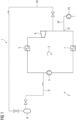
- the figure 1 shows schematically and by way of example a device 1 comprising a closed gas system 2 with a working circuit 3, in which a compressor 4 for a working fluid, a first heat exchanger 5 for heating the working fluid, an expander 6 (gas expansion turbine) and a second Heat exchanger 7 are arranged to cool the working fluid.
- a first gas line 9 branches off between the compressor 4 and the first heat exchanger 5 from the working circuit 3 and opens into the first gas pressure vessel 8. Furthermore, a second gas line 10 branches off from the first gas pressure vessel 8 and opens out between the expander 6 and the second heat exchanger 7 in the work cycle 3.
- make-up with make-up point 21, make-up line 22 and make-up pump 23 is used to compensate for the normal gas loss in the system.
- a third gas line 11 branches off from the first gas pressure vessel 8 or from the second gas line 10 and opens into the working circuit 3 between the compressor 4 and the first heat exchanger 5.
- FIG. 2 three additional heat exchangers.
- a third heat exchanger 12 arranged in the first gas line 9 cools the gaseous working fluid, whereas a fourth heat exchanger 14 in the second gas line 10 and a fifth heat exchanger 15 in the third gas line 11 serve to heat the working fluid.
- first valve 13 in the first gas line 9 which is arranged after the third heat exchanger 12 in the direction of flow of the working fluid. This is the relative arrangement of the two components when the working fluid cools as it expands. If the working fluid heats up during relaxation, the arrangement of the valve 13 and the third heat exchanger 12 is reversed. This is in the figure 2 marked with a dashed double arrow.
- FIG. 1 In addition to the out figure 1 already known first gas pressure vessel 8, the embodiment of figure 2 a second gas pressure tank 19 which is connected in parallel to the first gas pressure tank 8 . A corresponding second valve 20 is in the figure 2 shown. Typically, the gas pressure tanks 8, 19 can be operated at different pressure levels.
- a useful addition to the concept presented is the installation of a thermal storage device 16, which is connected to the third 12, fourth 14 or fifth heat exchanger 15 via switchable connecting lines A, B, C.
Landscapes
- Engineering & Computer Science (AREA)
- Chemical & Material Sciences (AREA)
- Combustion & Propulsion (AREA)
- Mechanical Engineering (AREA)
- General Engineering & Computer Science (AREA)
- Filling Or Discharging Of Gas Storage Vessels (AREA)
- Engine Equipment That Uses Special Cycles (AREA)
Claims (17)
- Installation (1) comprenant un système (2) fermé pour du gaz ayant un circuit (3) de travail, dans lequel sont montés un compresseur (4) d'un fluide de travail, un premier échangeur de chaleur (5) pour chauffer le fluide de travail, un détendeur (6) et un deuxième échangeur de chaleur (7) pour refroidir le fluide de travail, comprenant un premier récipient (8) tenant la pression pour du gaz et un premier conduit (9) pour du gaz, qui, entre le compresseur (4) et le premier échangeur de chaleur (5), bifurque du circuit (3) de travail et débouche dans le premier récipient (8) tenant la pression pour du gaz, ainsi qu'un deuxième conduit (10) pour du gaz, qui bifurque du premier récipient (8) tenant la pression pour du gaz, caractérisé en ce que le deuxième conduit (10) pour du gaz débouche dans le circuit (3) de travail entre le détendeur (6) et le deuxième échangeur de chaleur (7).
- Installation (1) suivant la revendication 1, dans laquelle un troisième conduit (11) pour du gaz bifurque du récipient (8) tenant la pression pour du gaz ou du deuxième conduit (10) pour du gaz et débouche dans le circuit (3) de travail entre le compresseur (4) et le premier échangeur de chaleur (5) .
- Installation (1) suivant l'une des revendications précédentes, dans lequel un troisième échangeur de chaleur (12) est monté dans le premier conduit (9) pour du gaz.
- Installation (1) suivant la revendication 3, dans lequel une première vanne (13) est montée dans le premier conduit (9) pour du gaz, dans le sens d'écoulement du fluide de travail en aval du troisième échangeur de chaleur (12).
- Installation (1) suivant la revendication 3, dans lequel une première vanne (13) est montée dans le premier conduit (9) pour du gaz, dans le sens d'écoulement du fluide de travail en amont du troisième échangeur de chaleur (12).
- Installation (1) suivant la revendication 2, dans lequel un quatrième échangeur de chaleur (14) est monté dans le deuxième conduit (10) pour du gaz et un cinquième échangeur de chaleur (15) est monté dans le troisième conduit (11) pour du gaz.
- Installation (1) suivant les revendications 3 et 6, dans lequel au moins un accumulateur (16) thermique communique par des conduits (A, B, C) de liaison pouvant être commutés avec le troisième (12), le quatrième (14) ou le cinquième échangeur de chaleur (15).
- Installation (1) suivant l'une des revendications précédentes, dans lequel du fluide de travail peut être réalimenté entre le détendeur (6) et le deuxième échangeur de chaleur (7).
- Installation (1) suivant l'une des revendications précédentes, dans lequel au moins un deuxième récipient (19) tenant la pression pour du gaz est monté en parallèle au premier récipient (8) tenant la pression pour du gaz et les récipients (8, 19) tenant la pression pour du gaz peuvent fonctionner à des niveaux de pression différents.
- Installation (1) suivant la revendication 9, dans lequel le compresseur (4) comprend au moins deux étages (17) de compresseur et un cinquième conduit (18) pour du gaz bifurque du circuit (3) entre deux étages (17) du compresseur et débouche dans au moins l'un des récipients (8, 19) tenant la pression pour du gaz.
- Procédé de régulation de la pression dans un système (2) fermé pour du gaz, dans lequel on comprime, chauffe, détend et refroidit, de manière répétée en succession, un fluide de travail dans un circuit (3) de travail,
dans lequel
pour la régulation d'une pression dans le système (2) pour du gaz, on prélève un courant partiel du fluide de travail du circuit (3) de travail et on le stocke ou on réinjecte dans le circuit (3) de travail une quantité de fluide de travail stockée, caractérisé en ce que on réinjecte dans le circuit de travail la quantité de fluide de travail stockée entre la détente et le refroidissement du fluide de travail. - Procédé suivant la revendication 11, dans lequel on prélève le fluide de travail du système (2) fermé pour du gaz, après qu'il a été comprimé, au moins en partie, et avant qu'il ait été chauffé par échange de chaleur.
- Procédé suivant l'une des revendications 11 ou 12, dans lequel on refroidit le fluide de travail prélevé avant de l'injecter.
- Procédé suivant la revendication 13, dans lequel on refroidit le fluide de travail, pour un coefficient Joule-Thomson positif, d'abord par un échange de chaleur et on le détend ensuite, au moyen d'une vanne (13, 20), dans un récipient (8, 19) tenant la pression pour du gaz, et pour un coefficient Joule-Thomson négatif, on le détend d'abord par la vanne (13, 20) et puis on le refroidit par un échange de chaleur et ensuite on l'injecte.
- Procédé suivant l'une des revendications 11 à 14, dans lequel on chauffe le fluide de travail avant de le réinjecter dans le circuit (3) de travail.
- Procédé suivant les revendications 13 et 15, dans lequel on charge un accumulateur (16) thermique lors du refroidissement du fluide de travail et on le décharge lors du chauffage du fluide de travail.
- Procédé suivant les revendications 11 à 16, dans lequel on envoie, à des récipients (8, 19) tenant la pression pour du gaz différents, du fluide de travail prélevé du circuit (2) de travail à des pressions différentes.
Applications Claiming Priority (2)
| Application Number | Priority Date | Filing Date | Title |
|---|---|---|---|
| EP19206843.5A EP3816413A1 (fr) | 2019-11-04 | 2019-11-04 | Régulation de pression pour processus cyclique fermé à effet joule |
| PCT/EP2020/069988 WO2021089204A1 (fr) | 2019-11-04 | 2020-07-15 | Régulation de pression pour cycles de brayton fermés |
Publications (3)
| Publication Number | Publication Date |
|---|---|
| EP4004349A1 EP4004349A1 (fr) | 2022-06-01 |
| EP4004349B1 true EP4004349B1 (fr) | 2023-08-30 |
| EP4004349C0 EP4004349C0 (fr) | 2023-08-30 |
Family
ID=68426262
Family Applications (2)
| Application Number | Title | Priority Date | Filing Date |
|---|---|---|---|
| EP19206843.5A Withdrawn EP3816413A1 (fr) | 2019-11-04 | 2019-11-04 | Régulation de pression pour processus cyclique fermé à effet joule |
| EP20746900.8A Active EP4004349B1 (fr) | 2019-11-04 | 2020-07-15 | Régulation de pression pour processus cyclique fermé à effet joule |
Family Applications Before (1)
| Application Number | Title | Priority Date | Filing Date |
|---|---|---|---|
| EP19206843.5A Withdrawn EP3816413A1 (fr) | 2019-11-04 | 2019-11-04 | Régulation de pression pour processus cyclique fermé à effet joule |
Country Status (6)
| Country | Link |
|---|---|
| US (1) | US12188379B2 (fr) |
| EP (2) | EP3816413A1 (fr) |
| JP (1) | JP7459241B2 (fr) |
| KR (1) | KR102654114B1 (fr) |
| ES (1) | ES2964929T3 (fr) |
| WO (1) | WO2021089204A1 (fr) |
Families Citing this family (2)
| Publication number | Priority date | Publication date | Assignee | Title |
|---|---|---|---|---|
| KR102485204B1 (ko) * | 2021-05-11 | 2023-01-06 | 한국전력공사 | 터빈 발전 시스템 |
| DE102023202959A1 (de) * | 2023-03-30 | 2024-10-02 | Deutsches Zentrum für Luft- und Raumfahrt e.V. | Leistungsanpassungsvorrichtung und Verfahren zur Leistungsanpassung für eine nach dem geschlossenen Brayton-Kreisprozess arbeitende thermodynamische Maschine |
Family Cites Families (19)
| Publication number | Priority date | Publication date | Assignee | Title |
|---|---|---|---|---|
| CH482918A (de) * | 1967-11-08 | 1969-12-15 | Sulzer Ag | Geschlossene Gasturbinenanlage mit CO2 als Arbeitsmittel |
| CH599460A5 (fr) * | 1975-12-23 | 1978-05-31 | Bbc Brown Boveri & Cie | |
| JPS59206617A (ja) | 1983-05-09 | 1984-11-22 | Kawasaki Heavy Ind Ltd | 密閉サイクルガスタービンの出力制御装置 |
| US5131231A (en) * | 1991-08-02 | 1992-07-21 | Allied-Signal | Method for operating a closed Brayton engine and engine adapted for use with method |
| JP3160469B2 (ja) * | 1994-06-23 | 2001-04-25 | 三菱重工業株式会社 | クローズドブレイトンサイクルガスタービンの出力制御方法と装置 |
| JP3020853B2 (ja) | 1995-11-24 | 2000-03-15 | 株式会社東芝 | 水素燃焼ガスタービンプラント |
| JP2000154733A (ja) | 1998-11-19 | 2000-06-06 | Mitsubishi Heavy Ind Ltd | クローズドブレイトンサイクルガスタービン装置 |
| JP2003056312A (ja) * | 2001-08-09 | 2003-02-26 | Kobe Steel Ltd | 閉サイクルガスタービンおよび同ガスタービンを用いた発電システム |
| DE102010034231A1 (de) * | 2010-08-07 | 2012-02-09 | Daimler Ag | Verfahren und Vorrichtung zur Energierückgewinnung aus einem Abgasstrom eines Verbrennungsmotors |
| EP2888456A2 (fr) * | 2012-08-22 | 2015-07-01 | Hi Eff Utility Rescue LLC | Système générateur d'énergie à haut rendement et améliorations de système |
| US9032734B2 (en) | 2012-09-26 | 2015-05-19 | Supercritical Technologies, Inc. | Modular power infrastructure network, and associated systems and methods |
| EP2808500A1 (fr) * | 2013-05-31 | 2014-12-03 | Siemens Aktiengesellschaft | Pompe à chaleur dotée d'une première machine thermique à énergie fluidique et d'une seconde machine thermique à énergie fluidique |
| JP6343587B2 (ja) * | 2015-05-18 | 2018-06-13 | 株式会社神戸製鋼所 | 圧縮空気貯蔵発電方法及び圧縮空気貯蔵発電装置 |
| JP2017008727A (ja) * | 2015-06-16 | 2017-01-12 | 株式会社神戸製鋼所 | 圧縮空気貯蔵発電装置及び圧縮空気貯蔵発電方法 |
| KR101816021B1 (ko) | 2017-06-09 | 2018-01-08 | 한국전력공사 | 복합 발전장치 |
| CN108591027B (zh) * | 2018-03-29 | 2019-08-06 | 华北电力大学 | 一种气/液双状态的大型压缩空气储能系统 |
| EP3734027A1 (fr) | 2019-05-02 | 2020-11-04 | Siemens Aktiengesellschaft | Regazéification de gaz naturel liquéfié |
| EP3969732B1 (fr) * | 2019-05-17 | 2025-03-19 | 8 Rivers Capital, LLC | Contrôle d'inventaire à cycle fermé |
| CN113738620A (zh) * | 2021-08-09 | 2021-12-03 | 势加透博(上海)能源科技有限公司 | 压缩气体储能装置和方法 |
-
2019
- 2019-11-04 EP EP19206843.5A patent/EP3816413A1/fr not_active Withdrawn
-
2020
- 2020-07-15 JP JP2022520775A patent/JP7459241B2/ja active Active
- 2020-07-15 KR KR1020227018377A patent/KR102654114B1/ko active Active
- 2020-07-15 US US17/769,387 patent/US12188379B2/en active Active
- 2020-07-15 EP EP20746900.8A patent/EP4004349B1/fr active Active
- 2020-07-15 WO PCT/EP2020/069988 patent/WO2021089204A1/fr not_active Ceased
- 2020-07-15 ES ES20746900T patent/ES2964929T3/es active Active
Also Published As
| Publication number | Publication date |
|---|---|
| KR20220090569A (ko) | 2022-06-29 |
| US20240133321A1 (en) | 2024-04-25 |
| US20240229685A9 (en) | 2024-07-11 |
| WO2021089204A1 (fr) | 2021-05-14 |
| EP3816413A1 (fr) | 2021-05-05 |
| JP7459241B2 (ja) | 2024-04-01 |
| ES2964929T3 (es) | 2024-04-10 |
| KR102654114B1 (ko) | 2024-04-04 |
| JP2023500196A (ja) | 2023-01-05 |
| EP4004349A1 (fr) | 2022-06-01 |
| EP4004349C0 (fr) | 2023-08-30 |
| US12188379B2 (en) | 2025-01-07 |
Similar Documents
| Publication | Publication Date | Title |
|---|---|---|
| EP1917428B1 (fr) | Procédé d'operation d'une centrale electrique equipee d'un reservoir sous pression | |
| DE68926220T2 (de) | Verfahren und Vorrichtung zur Dampfkrafterzeugung | |
| EP2480762B1 (fr) | Centrale thermique comprenant vanne de régulation de surcharge | |
| EP0874188B1 (fr) | Procédé pour le traitement d'un gaz liquéfié cryogénique | |
| EP2603672B1 (fr) | Générateur de vapeur à récupération de chaleur | |
| EP2067940B2 (fr) | Procédé de fonctionnement d'ne centrale à cycle combiné, et centrale à cycle combiné pour la mise en oeuvre dudit procédé | |
| DE4210541A1 (de) | Verfahren zum Betrieb einer Gasturbogruppe | |
| DE102015109898A1 (de) | Dampfkraftwerk und Verfahren zu dessen Betrieb | |
| DE102013225543B3 (de) | Dampfspeicherung mit Latentwärmespeicher und Dampf-Thermokompressor | |
| EP4004349B1 (fr) | Régulation de pression pour processus cyclique fermé à effet joule | |
| EP2326800B1 (fr) | Centrale à vapeur destinée à la production d'énergie électrique | |
| CH622317A5 (fr) | ||
| EP1892457B1 (fr) | Procédé et dispositif destinés à l'enregistrement de gaz combustible, en particulier de gaz naturel | |
| EP3146181B1 (fr) | Procédé d'exploitation pour une centrale électrique équipée d'un système de carburant d'urgence | |
| EP0995891B1 (fr) | Turbomachine et sa méthode d'opération | |
| AT518299B1 (de) | Verfahren zum Regasifizieren von tiefkalt verflüssigtem Gas | |
| EP1801363A1 (fr) | Centrale électrique | |
| DE102022205134B3 (de) | Druckaufbausystem und Druckaufbauverfahren zum Entnehmen eines Druckgases aus einer Speichervorrichtung zur Aufbewahrung eines Flüssiggases | |
| DE102011075557A1 (de) | Leitungskreis und Verfahren zum Betreiben eines Leitungskreises zur Abwärmenutzung einer Brennkraftmaschine | |
| EP3662145B1 (fr) | Procédé amélioré de génération d'électricité lors de la regazéification d'un fluide par réduction de pression surcritique | |
| DE3505320C2 (fr) | ||
| DE102023134303A1 (de) | Verfahren und Vorrichtung zur Energiegewinnung unter Verwendung eines kryogenen Mediums | |
| EP2805031A1 (fr) | Centrale électrique et procédé permettant de faire fonctionner une centrale électrique | |
| DE2711287A1 (de) | Kuehlkreislauf fuer ein kraftwerk sowie verfahren zum betrieb des kuehlkreislaufes | |
| DE102013205053B4 (de) | Verfahren zum Betrieb eines einen Wasser-Dampf-Kreislauf aufweisenden Kraftwerks |
Legal Events
| Date | Code | Title | Description |
|---|---|---|---|
| STAA | Information on the status of an ep patent application or granted ep patent |
Free format text: STATUS: UNKNOWN |
|
| STAA | Information on the status of an ep patent application or granted ep patent |
Free format text: STATUS: THE INTERNATIONAL PUBLICATION HAS BEEN MADE |
|
| PUAI | Public reference made under article 153(3) epc to a published international application that has entered the european phase |
Free format text: ORIGINAL CODE: 0009012 |
|
| STAA | Information on the status of an ep patent application or granted ep patent |
Free format text: STATUS: REQUEST FOR EXAMINATION WAS MADE |
|
| 17P | Request for examination filed |
Effective date: 20220228 |
|
| AK | Designated contracting states |
Kind code of ref document: A1 Designated state(s): AL AT BE BG CH CY CZ DE DK EE ES FI FR GB GR HR HU IE IS IT LI LT LU LV MC MK MT NL NO PL PT RO RS SE SI SK SM TR |
|
| REG | Reference to a national code |
Ref country code: DE Ref legal event code: R079 Free format text: PREVIOUS MAIN CLASS: F01K0025000000 Ipc: F02C0006160000 Ref document number: 502020005012 Country of ref document: DE |
|
| DAV | Request for validation of the european patent (deleted) | ||
| DAX | Request for extension of the european patent (deleted) | ||
| GRAP | Despatch of communication of intention to grant a patent |
Free format text: ORIGINAL CODE: EPIDOSNIGR1 |
|
| STAA | Information on the status of an ep patent application or granted ep patent |
Free format text: STATUS: GRANT OF PATENT IS INTENDED |
|
| RIC1 | Information provided on ipc code assigned before grant |
Ipc: F01K 13/00 20060101ALI20230131BHEP Ipc: F02C 1/10 20060101ALI20230131BHEP Ipc: F01K 13/02 20060101ALI20230131BHEP Ipc: F01K 25/00 20060101ALI20230131BHEP Ipc: F02C 6/16 20060101AFI20230131BHEP |
|
| INTG | Intention to grant announced |
Effective date: 20230217 |
|
| GRAS | Grant fee paid |
Free format text: ORIGINAL CODE: EPIDOSNIGR3 |
|
| GRAA | (expected) grant |
Free format text: ORIGINAL CODE: 0009210 |
|
| STAA | Information on the status of an ep patent application or granted ep patent |
Free format text: STATUS: THE PATENT HAS BEEN GRANTED |
|
| AK | Designated contracting states |
Kind code of ref document: B1 Designated state(s): AL AT BE BG CH CY CZ DE DK EE ES FI FR GB GR HR HU IE IS IT LI LT LU LV MC MK MT NL NO PL PT RO RS SE SI SK SM TR |
|
| REG | Reference to a national code |
Ref country code: GB Ref legal event code: FG4D Free format text: NOT ENGLISH |
|
| REG | Reference to a national code |
Ref country code: CH Ref legal event code: EP |
|
| REG | Reference to a national code |
Ref country code: DE Ref legal event code: R096 Ref document number: 502020005012 Country of ref document: DE |
|
| REG | Reference to a national code |
Ref country code: IE Ref legal event code: FG4D Free format text: LANGUAGE OF EP DOCUMENT: GERMAN |
|
| U01 | Request for unitary effect filed |
Effective date: 20230908 |
|
| U07 | Unitary effect registered |
Designated state(s): AT BE BG DE DK EE FI FR IT LT LU LV MT NL PT SE SI Effective date: 20230915 |
|
| PG25 | Lapsed in a contracting state [announced via postgrant information from national office to epo] |
Ref country code: GR Free format text: LAPSE BECAUSE OF FAILURE TO SUBMIT A TRANSLATION OF THE DESCRIPTION OR TO PAY THE FEE WITHIN THE PRESCRIBED TIME-LIMIT Effective date: 20231201 |
|
| PG25 | Lapsed in a contracting state [announced via postgrant information from national office to epo] |
Ref country code: IS Free format text: LAPSE BECAUSE OF FAILURE TO SUBMIT A TRANSLATION OF THE DESCRIPTION OR TO PAY THE FEE WITHIN THE PRESCRIBED TIME-LIMIT Effective date: 20231230 |
|
| PG25 | Lapsed in a contracting state [announced via postgrant information from national office to epo] |
Ref country code: RS Free format text: LAPSE BECAUSE OF FAILURE TO SUBMIT A TRANSLATION OF THE DESCRIPTION OR TO PAY THE FEE WITHIN THE PRESCRIBED TIME-LIMIT Effective date: 20230830 Ref country code: NO Free format text: LAPSE BECAUSE OF FAILURE TO SUBMIT A TRANSLATION OF THE DESCRIPTION OR TO PAY THE FEE WITHIN THE PRESCRIBED TIME-LIMIT Effective date: 20231130 Ref country code: IS Free format text: LAPSE BECAUSE OF FAILURE TO SUBMIT A TRANSLATION OF THE DESCRIPTION OR TO PAY THE FEE WITHIN THE PRESCRIBED TIME-LIMIT Effective date: 20231230 Ref country code: HR Free format text: LAPSE BECAUSE OF FAILURE TO SUBMIT A TRANSLATION OF THE DESCRIPTION OR TO PAY THE FEE WITHIN THE PRESCRIBED TIME-LIMIT Effective date: 20230830 Ref country code: GR Free format text: LAPSE BECAUSE OF FAILURE TO SUBMIT A TRANSLATION OF THE DESCRIPTION OR TO PAY THE FEE WITHIN THE PRESCRIBED TIME-LIMIT Effective date: 20231201 |
|
| PG25 | Lapsed in a contracting state [announced via postgrant information from national office to epo] |
Ref country code: PL Free format text: LAPSE BECAUSE OF FAILURE TO SUBMIT A TRANSLATION OF THE DESCRIPTION OR TO PAY THE FEE WITHIN THE PRESCRIBED TIME-LIMIT Effective date: 20230830 |
|
| REG | Reference to a national code |
Ref country code: ES Ref legal event code: FG2A Ref document number: 2964929 Country of ref document: ES Kind code of ref document: T3 Effective date: 20240410 |
|
| PG25 | Lapsed in a contracting state [announced via postgrant information from national office to epo] |
Ref country code: SM Free format text: LAPSE BECAUSE OF FAILURE TO SUBMIT A TRANSLATION OF THE DESCRIPTION OR TO PAY THE FEE WITHIN THE PRESCRIBED TIME-LIMIT Effective date: 20230830 Ref country code: RO Free format text: LAPSE BECAUSE OF FAILURE TO SUBMIT A TRANSLATION OF THE DESCRIPTION OR TO PAY THE FEE WITHIN THE PRESCRIBED TIME-LIMIT Effective date: 20230830 Ref country code: CZ Free format text: LAPSE BECAUSE OF FAILURE TO SUBMIT A TRANSLATION OF THE DESCRIPTION OR TO PAY THE FEE WITHIN THE PRESCRIBED TIME-LIMIT Effective date: 20230830 Ref country code: SK Free format text: LAPSE BECAUSE OF FAILURE TO SUBMIT A TRANSLATION OF THE DESCRIPTION OR TO PAY THE FEE WITHIN THE PRESCRIBED TIME-LIMIT Effective date: 20230830 |
|
| REG | Reference to a national code |
Ref country code: DE Ref legal event code: R097 Ref document number: 502020005012 Country of ref document: DE |
|
| PLBE | No opposition filed within time limit |
Free format text: ORIGINAL CODE: 0009261 |
|
| STAA | Information on the status of an ep patent application or granted ep patent |
Free format text: STATUS: NO OPPOSITION FILED WITHIN TIME LIMIT |
|
| 26N | No opposition filed |
Effective date: 20240603 |
|
| U20 | Renewal fee for the european patent with unitary effect paid |
Year of fee payment: 5 Effective date: 20240725 |
|
| PG25 | Lapsed in a contracting state [announced via postgrant information from national office to epo] |
Ref country code: MC Free format text: LAPSE BECAUSE OF FAILURE TO SUBMIT A TRANSLATION OF THE DESCRIPTION OR TO PAY THE FEE WITHIN THE PRESCRIBED TIME-LIMIT Effective date: 20230830 |
|
| REG | Reference to a national code |
Ref country code: CH Ref legal event code: PL |
|
| PG25 | Lapsed in a contracting state [announced via postgrant information from national office to epo] |
Ref country code: CH Free format text: LAPSE BECAUSE OF NON-PAYMENT OF DUE FEES Effective date: 20240731 |
|
| PG25 | Lapsed in a contracting state [announced via postgrant information from national office to epo] |
Ref country code: IE Free format text: LAPSE BECAUSE OF NON-PAYMENT OF DUE FEES Effective date: 20240715 |
|
| U20 | Renewal fee for the european patent with unitary effect paid |
Year of fee payment: 6 Effective date: 20250725 |
|
| PGFP | Annual fee paid to national office [announced via postgrant information from national office to epo] |
Ref country code: ES Payment date: 20250811 Year of fee payment: 6 |
|
| PGFP | Annual fee paid to national office [announced via postgrant information from national office to epo] |
Ref country code: GB Payment date: 20250722 Year of fee payment: 6 |
|
| PG25 | Lapsed in a contracting state [announced via postgrant information from national office to epo] |
Ref country code: CY Free format text: LAPSE BECAUSE OF FAILURE TO SUBMIT A TRANSLATION OF THE DESCRIPTION OR TO PAY THE FEE WITHIN THE PRESCRIBED TIME-LIMIT; INVALID AB INITIO Effective date: 20200715 |
|
| PG25 | Lapsed in a contracting state [announced via postgrant information from national office to epo] |
Ref country code: HU Free format text: LAPSE BECAUSE OF FAILURE TO SUBMIT A TRANSLATION OF THE DESCRIPTION OR TO PAY THE FEE WITHIN THE PRESCRIBED TIME-LIMIT; INVALID AB INITIO Effective date: 20200715 |