EP4004358B1 - Konvergent-divergentes klappenpaar für eine turbinen-luftstrahl-triebwerksdüse mit variabler geometrie, deren klappen jeweils einen kühlluftumlaufkanal umfassen - Google Patents
Konvergent-divergentes klappenpaar für eine turbinen-luftstrahl-triebwerksdüse mit variabler geometrie, deren klappen jeweils einen kühlluftumlaufkanal umfassen Download PDFInfo
- Publication number
- EP4004358B1 EP4004358B1 EP20775387.2A EP20775387A EP4004358B1 EP 4004358 B1 EP4004358 B1 EP 4004358B1 EP 20775387 A EP20775387 A EP 20775387A EP 4004358 B1 EP4004358 B1 EP 4004358B1
- Authority
- EP
- European Patent Office
- Prior art keywords
- flap
- convergent
- divergent
- wall
- divergent flap
- Prior art date
- Legal status (The legal status is an assumption and is not a legal conclusion. Google has not performed a legal analysis and makes no representation as to the accuracy of the status listed.)
- Active
Links
Images


Classifications
-
- F—MECHANICAL ENGINEERING; LIGHTING; HEATING; WEAPONS; BLASTING
- F02—COMBUSTION ENGINES; HOT-GAS OR COMBUSTION-PRODUCT ENGINE PLANTS
- F02K—JET-PROPULSION PLANTS
- F02K1/00—Plants characterised by the form or arrangement of the jet pipe or nozzle; Jet pipes or nozzles peculiar thereto
- F02K1/06—Varying effective area of jet pipe or nozzle
- F02K1/12—Varying effective area of jet pipe or nozzle by means of pivoted flaps
- F02K1/1223—Varying effective area of jet pipe or nozzle by means of pivoted flaps of two series of flaps, the upstream series having its flaps hinged at their upstream ends on a fixed structure and the downstream series having its flaps hinged at their upstream ends on the downstream ends of the flaps of the upstream series
-
- F—MECHANICAL ENGINEERING; LIGHTING; HEATING; WEAPONS; BLASTING
- F02—COMBUSTION ENGINES; HOT-GAS OR COMBUSTION-PRODUCT ENGINE PLANTS
- F02K—JET-PROPULSION PLANTS
- F02K1/00—Plants characterised by the form or arrangement of the jet pipe or nozzle; Jet pipes or nozzles peculiar thereto
- F02K1/78—Other construction of jet pipes
- F02K1/82—Jet pipe walls, e.g. liners
- F02K1/822—Heat insulating structures or liners, cooling arrangements, e.g. post combustion liners; Infrared radiation suppressors
-
- F—MECHANICAL ENGINEERING; LIGHTING; HEATING; WEAPONS; BLASTING
- F02—COMBUSTION ENGINES; HOT-GAS OR COMBUSTION-PRODUCT ENGINE PLANTS
- F02K—JET-PROPULSION PLANTS
- F02K3/00—Plants including a gas turbine driving a compressor or a ducted fan
- F02K3/08—Plants including a gas turbine driving a compressor or a ducted fan with supplementary heating of the working fluid; Control thereof
- F02K3/10—Plants including a gas turbine driving a compressor or a ducted fan with supplementary heating of the working fluid; Control thereof by after-burners
-
- F—MECHANICAL ENGINEERING; LIGHTING; HEATING; WEAPONS; BLASTING
- F05—INDEXING SCHEMES RELATING TO ENGINES OR PUMPS IN VARIOUS SUBCLASSES OF CLASSES F01-F04
- F05D—INDEXING SCHEME FOR ASPECTS RELATING TO NON-POSITIVE-DISPLACEMENT MACHINES OR ENGINES, GAS-TURBINES OR JET-PROPULSION PLANTS
- F05D2220/00—Application
- F05D2220/30—Application in turbines
- F05D2220/32—Application in turbines in gas turbines
- F05D2220/323—Application in turbines in gas turbines for aircraft propulsion, e.g. jet engines
-
- F—MECHANICAL ENGINEERING; LIGHTING; HEATING; WEAPONS; BLASTING
- F05—INDEXING SCHEMES RELATING TO ENGINES OR PUMPS IN VARIOUS SUBCLASSES OF CLASSES F01-F04
- F05D—INDEXING SCHEME FOR ASPECTS RELATING TO NON-POSITIVE-DISPLACEMENT MACHINES OR ENGINES, GAS-TURBINES OR JET-PROPULSION PLANTS
- F05D2240/00—Components
- F05D2240/10—Stators
- F05D2240/12—Fluid guiding means, e.g. vanes
- F05D2240/128—Nozzles
-
- F—MECHANICAL ENGINEERING; LIGHTING; HEATING; WEAPONS; BLASTING
- F05—INDEXING SCHEMES RELATING TO ENGINES OR PUMPS IN VARIOUS SUBCLASSES OF CLASSES F01-F04
- F05D—INDEXING SCHEME FOR ASPECTS RELATING TO NON-POSITIVE-DISPLACEMENT MACHINES OR ENGINES, GAS-TURBINES OR JET-PROPULSION PLANTS
- F05D2250/00—Geometry
- F05D2250/30—Arrangement of components
- F05D2250/32—Arrangement of components according to their shape
- F05D2250/323—Arrangement of components according to their shape convergent
-
- F—MECHANICAL ENGINEERING; LIGHTING; HEATING; WEAPONS; BLASTING
- F05—INDEXING SCHEMES RELATING TO ENGINES OR PUMPS IN VARIOUS SUBCLASSES OF CLASSES F01-F04
- F05D—INDEXING SCHEME FOR ASPECTS RELATING TO NON-POSITIVE-DISPLACEMENT MACHINES OR ENGINES, GAS-TURBINES OR JET-PROPULSION PLANTS
- F05D2250/00—Geometry
- F05D2250/30—Arrangement of components
- F05D2250/32—Arrangement of components according to their shape
- F05D2250/324—Arrangement of components according to their shape divergent
-
- F—MECHANICAL ENGINEERING; LIGHTING; HEATING; WEAPONS; BLASTING
- F05—INDEXING SCHEMES RELATING TO ENGINES OR PUMPS IN VARIOUS SUBCLASSES OF CLASSES F01-F04
- F05D—INDEXING SCHEME FOR ASPECTS RELATING TO NON-POSITIVE-DISPLACEMENT MACHINES OR ENGINES, GAS-TURBINES OR JET-PROPULSION PLANTS
- F05D2260/00—Function
- F05D2260/20—Heat transfer, e.g. cooling
- F05D2260/201—Heat transfer, e.g. cooling by impingement of a fluid
-
- Y—GENERAL TAGGING OF NEW TECHNOLOGICAL DEVELOPMENTS; GENERAL TAGGING OF CROSS-SECTIONAL TECHNOLOGIES SPANNING OVER SEVERAL SECTIONS OF THE IPC; TECHNICAL SUBJECTS COVERED BY FORMER USPC CROSS-REFERENCE ART COLLECTIONS [XRACs] AND DIGESTS
- Y02—TECHNOLOGIES OR APPLICATIONS FOR MITIGATION OR ADAPTATION AGAINST CLIMATE CHANGE
- Y02T—CLIMATE CHANGE MITIGATION TECHNOLOGIES RELATED TO TRANSPORTATION
- Y02T50/00—Aeronautics or air transport
- Y02T50/60—Efficient propulsion technologies, e.g. for aircraft
Definitions
- the present invention relates to the field of turbojet engines intended for the propulsion of aircraft capable of supersonic flight, and relates more particularly to a convergent flap-divergent flap pair for a turbojet nozzle of the convergent-divergent type with variable geometry, a nozzle equipped with such a convergent flap-divergent flap pair, and a turbojet comprising such a nozzle.
- Turbojet engines intended for supersonic flight generally include a postcombustion channel whose outlet is delimited by an axisymmetric nozzle of the convergent-divergent type, in order to allow the acceleration of the flow of air leaving the engine to speeds greater than Mach 1.
- such a nozzle has a variable geometry, making it possible to vary the internal section of the nozzle and in particular the position and the shape of the neck of the nozzle.
- such a nozzle comprises a set of movable internal flaps intended to channel the flow of gas leaving the reactor, this assembly comprising an annular row of convergent flaps followed by an annular row of divergent flaps.
- the divergent flaps are generally hinged at their respective upstream ends on respective downstream ends of the convergent flaps, and the convergent flaps are themselves hinged at their respective upstream ends on a stator structure of the turbojet engine.
- the set of mobile internal flaps therefore consists of an annular row of convergent flap-divergent flap pairs.
- Such a nozzle further comprises an annular row of movable external flaps surrounding the set of movable internal flaps.
- cooling air must be taken from the working air flow of the turbojet engine, which is why it is desirable to limit the quantity of air necessary for cooling in order to optimize the propulsion performance of the engine.
- the aim of the invention is in particular to at least partially solve the above problem, and in particular to propose an effective solution for cooling the mobile internal flaps of a convergent-divergent nozzle with variable geometry of a turbojet engine, while limiting the negative impact of such cooling on the propulsion performance of the turbojet engine.
- the diverging flap has two opposite side end walls each connecting the respective inner wall of the diverging flap to the outer wall of the diverging flap, so that each of the air circulation cavity of cooling and the impact cooling cavity is further delimited by the respective side end walls of the diverging flap.
- Each of the two respective lateral end walls of the diverging flap is provided with air passage orifices through which the impact cooling cavity opens outwards.
- the invention thus allows efficient cooling of mobile internal flaps, requiring only a moderate quantity of air, and therefore having a moderate impact on the performance of a turbojet engine equipped with such a nozzle.
- the invention thus makes it possible to improve the mechanical strength of mobile internal shutters and to control the thermal behavior of the latter.
- the invention also makes it possible to limit the temperature of such a nozzle, and therefore to limit the infrared signal thereof.
- Limiting the temperature of the nozzle also allows the use of a wider choice of materials within it, in particular electromagnetic absorption materials which are generally not very tolerant of high temperatures.
- the diverging flap comprises a respective downstream end wall providing at least one opening through which the impact cooling cavity opens downstream.
- the respective downstream end wall of the diverging flap connects the respective outer wall of the diverging flap to the multiperforated plate of the diverging flap.
- the diverging flap comprises a closing wall, connecting the multiperforated plate of the diverging flap to the respective internal wall of the diverging flap, so as to close an upstream end of the impact cooling cavity of the diverging flap.
- the invention also relates to a nozzle of the convergent-divergent type with variable geometry for a turbojet engine, comprising convergent-divergent flap pairs distributed around an axis of the nozzle and of which at least some are convergent-divergent flap pairs of the type described above, and a combustion gas circulation channel delimited at least by the respective internal combustion gas channeling surfaces of the respective internal walls of the respective convergent flaps and of the respective divergent flaps of the convergent flap-divergent flap pairs of the type described above.
- the convergent flap-divergent flap pairs of the type described above form convergent flap-divergent flap follower pairs
- the nozzle further comprising controlled convergent flap-divergent flap pairs arranged circumferentially with the convergent flap-divergent flap follower pairs and comprising respective divergent flaps comprising respective combustion gas channeling walls having respective combustion gas channeling internal surfaces delimiting the combustion gas circulation channel.
- the air passage orifices of the respective lateral end walls of the respective divergent flaps of the follower convergent flap-divergent flap pairs open into the combustion gas circulation channel, facing the respective combustion gas channeling walls of the respective divergent flaps of the controlled convergent flap-divergent flap pairs.
- the respective divergent flaps of the convergent flap-divergent flap pairs controlled are single-skin flaps.
- the invention also relates to a turbojet engine for an aircraft, comprising a post-combustion channel surrounded by a cooling plenum separated from the post-combustion channel by a thermal protection jacket, and a nozzle of the type described above, in which the respective cooling air circulation cavities of the convergent flaps of the convergent flap-divergent flap pairs of the type described above of the nozzle are connected to the cooling plenum surrounding the post-combustion channel.
- turbojet engine 10 for example double-spool and turbofan, intended for the propulsion of an aircraft capable of supersonic flight, and therefore intended in particular to be installed in the fuselage of such an aircraft.
- the axial direction X is the direction of the longitudinal axis 11 of the turbojet engine.
- the radial direction R is at all points a direction orthogonal to the longitudinal axis 11 and passing through the latter
- the circumferential direction C is at all points a direction orthogonal to the radial direction R and to the longitudinal axis 11. 1.
- the qualifiers "upstream” and “downstream” are defined by reference to a general direction D of the flow of gases in the turbojet engine 10.
- Such a turbojet engine 10 comprises, by way of illustration, from upstream to downstream, an air inlet 12, a low pressure compressor 14, a high pressure compressor 16, a combustion chamber 18, a high pressure turbine 20, a low pressure turbine 22, a postcombustion channel 26, and a nozzle 28 of the convergent-divergent type with variable geometry. These members of the turbojet engine are all centered along the longitudinal axis 11 of the turbojet engine.
- the high pressure compressor 16, the combustion chamber 18, and the high pressure 20 and low pressure 22 turbines define a primary stream PF.
- the latter is surrounded by a secondary stream SF of the turbomachine which extends from upstream to downstream from an outlet of the compressor low pressure.
- the air F1 which has entered through the air inlet 12 and which has been compressed by the low pressure compressor 14 is then divided into a primary flow F2 which circulates in the primary stream and into a secondary flow F3 which circulates in the secondary stream 30.
- the primary stream F2 is then compressed further in the high pressure compressor 16, then mixed with fuel and ignited in the combustion chamber 18, before undergoing expansion in the high pressure turbine 20 then in the low pressure turbine 22.
- the gas flow F4 consisting of the mixture of combustion gases from the primary stream and the secondary flow F3, then circulates in the post-combustion channel 26, then escapes from the turbojet engine 10 through the nozzle 28.
- fuel is mixed with the flow of gas F4 within the afterburner channel 26, and the mixture thus formed is ignited within this afterburner channel, in order to generate additional thrust.
- the convergent-divergent configuration of the nozzle 28 then makes it possible to accelerate the flow of gas F4 to supersonic speeds.
- the postcombustion channel 26 comprises an outer casing 32 in the shape of a revolution, and a thermal protection jacket 34 extending coaxially to the outer casing 32 inside the latter.
- the outer casing 32 and the thermal protection jacket 34 delimit between them a cooling plenum 36 intended for the circulation of a flow of cooling air CF1 along the outer casing 32.
- the nozzle 28 comprises a set 38 of movable internal flaps externally delimiting a combustion gas circulation channel 39, which corresponds, within the turbojet engine, to a downstream end part of the postcombustion channel 26.
- the movable internal flaps thus make it possible to channel the flow of gas F4 at the outlet of the turbojet engine 10 in operation.
- the assembly 38 of movable internal flaps comprises, upstream, an annular row of convergent flaps 40, followed, downstream, by an annular row of divergent flaps 42.
- the divergent flaps 42 are articulated, at their respective upstream ends 44, respectively on respective downstream ends 46 of the convergent flaps 40.
- the convergent flaps 40 are themselves articulated at their respective upstream ends 48 on a stator structure 50 of the turbojet engine.
- the assembly 38 of mobile internal flaps therefore consists of an annular row of convergent flap-divergent flap pairs 52, the flaps of each pair being articulated so as to be capable of passing from a first extreme angular configuration, in which the convergent flap and the divergent flap form between them a maximum salient angle, to a second extreme angular configuration, in which the convergent flap and the divergent flap form between them a minimum salient angle less than the maximum salient angle, and vice versa, in a manner known per se.
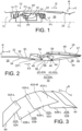
- assembly 38 comprises controlled convergent flap-divergent flap pairs 52A, and follower convergent flap-divergent flap pairs 52B, arranged alternately in the circumferential direction C. s convergent followers 40B and divergent flaps 42B followers. There picture 3 shows diverging flaps 42A, 42B respectively of controlled pairs 52A and following pairs 52B.
- the ordered pairs 52A are directly connected to respective actuating members 54 of the nozzle, which actuating members are mounted on the stator structure 50 of the turbojet engine, so as to directly control the movement of the controlled torques 52A.
- the follower pairs 52B cooperate with the adjacent controlled pairs 52A via drive members (not visible in the figures) configured to communicate a movement of the controlled pairs 52A to the follower pairs 52B.
- the converging flaps 40 each comprise a respective combustion gas channeling wall 56, extending in a respective longitudinal direction of the flap, and presenting, on a radially internal side, a respective internal combustion gas channeling surface 58, and, on a radially external side, a respective external surface 59.
- the divergent flaps 42 each comprise a respective combustion gas channeling wall 64, extending in a respective longitudinal direction of the flap, and having, on a radially internal side, a respective internal combustion gas channeling surface 66, and, on a radially external side, a respective external surface 67.
- the nozzle 28 further comprises an annular row of movable external flaps 68 surrounding the assembly 38 of movable internal flaps ( picture 2 ) and articulated on the stator structure 50 of the turbojet engine so as to move in synchronization with the assembly 38 of mobile internal flaps.
- the cooling air coming from the cooling plenum 36 escapes freely downstream and to the sides after having contributed to the cooling of the outer casing 32, and possibly contributes in a marginal way to the cooling of the assembly 38 of movable internal flaps.
- the invention proposes an improvement of the nozzle 28 of the convergent-divergent type with variable geometry. More specifically, the invention allows an improvement in the cooling of the assembly 38 of mobile internal flaps, as will appear more clearly in what follows.
- FIG. 4 more particularly shows a convergent flap-divergent follower flap pair 52B, as well as, disposed radially opposite the latter, a movable external flap 68, illustrated very schematically.
- the explanations given below reference to figures 4 to 10 are valid for each of the converging flap-diverging follower flap 52B couples of the nozzle 28.
- the convergent flap-follower divergent flap couple 52B also visible on the figures 5A to 7 , comprises a convergent flap 40B and a divergent flap 42B.
- the divergent flap 42B is articulated at its upstream end 44 on the downstream end 46 of the convergent flap 40B, for example by means of an articulation by hinge 45, whereby the couple convergent flap-follower divergent flap 52B is capable of passing from a first extreme angular configuration ( figure 5A ), in which the convergent flap 40B and the divergent flap 42B form a maximum salient angle between them, at a second extreme angular configuration ( figure 5B ), in which the converging flap 40B and the diverging flap 42B make between them a minimum salient angle less than the maximum salient angle
- the converging flap 40B comprises a respective combustion gas channeling wall, referred to as internal wall 56 in the following, extending in a respective longitudinal direction of the flap, and having, on a radially internal side, a respective internal combustion gas channeling surface 58, and, on a radially external side, a respective external surface 59.
- the convergent flap 40B comprises a respective external wall 60, extending opposite the external surface 59 of the internal wall 56 of this flap ( figure 4 , 5A-5B And 7 ), for example parallel to the inner wall 56.
- the convergent flap 40B further comprises two respective opposite side end walls 72 each connecting the internal wall 56 of this flap to the external wall 60 of this flap ( figure 6 And 7 ).
- the convergent flap 40B comprises a respective cooling air circulation duct 70 ( figure 4 , 5A-5B , 7 ) defined between the inner wall 56 and the outer wall 60 of the flap 40B, and between the two side end walls 72 of this flap.
- the cooling air circulation duct 70 of the convergent flap 40B comprises, at its upstream end, an end piece 73 ( figure 4 ) configured to be connected to the cooling plenum 36 surrounding the afterburner channel 26 ( figure 2 ), so that the cooling air circulation duct 70 receives part of the cooling air flow CF1, in operation.
- cooling air circulation duct 70 is therefore delimited in particular by the outer surface 59 of the inner wall 56 of the flap ( figure 4 , 5A-5B , 7 ). This last wall is thus cooled by the air circulating in the cooling air circulation duct 70, in operation.
- the divergent flap 42B comprises a respective combustion gas channeling wall, referred to as internal wall 64 in the following, extending in a respective longitudinal direction of the flap, and having, on one radially internal side, a respective internal combustion gas channeling surface 66, and, on a radially external side, a respective external surface 67.
- an orthonormal reference X', Y', Z' is defined so that the direction X' corresponds to the longitudinal direction of the divergent flap 42B, and therefore in particular of the internal wall 64 thereof, and that the direction Y' corresponds to a transverse direction of the divergent flap, and the direction Z' corresponds to the direction of the thickness of the divergent flap.
- the divergent flap 42B further comprises a respective external wall 76 extending opposite the external surface 67 of the internal wall 64 of this flap, for example parallel to the internal wall 64, so that these two walls 64 and 76 define between them a cooling air circulation duct 78 respective of the divergent flap 42B ( figure 4 , 5A-5B , 7 ).
- the divergent flap 42B further comprises two respective side end walls 80 each connecting the internal wall 64 to the external wall 76 of the divergent flap ( figure 6 , 7 ), so that the two side end walls 80 close laterally (and therefore delimit between them) the cooling air circulation duct 78 of the divergent flap 42B.
- the cooling air circulation duct 78 of the divergent flap 42B is connected to the cooling air circulation duct 70 of the convergent flap 40B ( figure 5A , 5B ).
- the cooling air circulation duct 78 of the divergent flap 42B thus receives the flow of cooling air coming from the cooling air circulation duct 70 of the convergent flap 40B, or at least a majority part thereof, in operation.
- the cooling air circulation duct 78 of the divergent flap 42B comprises for this purpose a respective connection portion 82 cooperating by fitting with a respective end portion 84 of the cooling air circulation duct 70 of the convergent flap 40B ( figure 4 And 5A-5B ).
- the outer wall 60 of the convergent flap 40B comprises a respective main portion 85, for example of flat shape, and a respective end portion 86 which delimits a downstream part 84A of the end portion 84 of the cooling air circulation duct 70 of the convergent flap 40B ( figure 5A And 5B ).
- the end portion 86 is in the form of a portion of a cylinder of revolution with an axis coinciding with a pivot axis 87 around which the divergent flap 42B pivots with respect to the convergent flap 40B when the convergent flap-divergent follower flap 52B couple passes from one to the other of the first and second extreme angular configurations.
- the pivot axis 87 constitutes the axis of curvature of the end portion 86.
- the hinge joint 45 has an outer surface 45A of cylindrical shape of revolution centered on the pivot axis 87 and in contact with the end portion 86 of the outer wall 60 of the convergent flap 40B ( Figures 5A-5B And 7 ).
- the outer wall 76 of the divergent flap 42B comprises a respective main portion 89, for example of flat shape, and a respective end portion 88, which delimits the connection portion 82 of the air circulation duct of cooling 78 of the divergent flap, and which is of complementary shape to the end portion 86 of the outer wall 60 of the convergent flap 40B ( figure 5A And 5B ).
- the end portion 88 of the outer wall 76 of the divergent flap 42B thus has the same axis of curvature as the end portion 86 of the outer wall 60 of the convergent flap 40B.
- the curved shape of the end portions 86 and 88 allows a relative pivoting movement between the convergent flap 40B and the divergent flap 42B for the passage from one to the other of the first and second configurations of the pair convergent flap-divergent follower flap 52B.
- the end portion 88 of the outer wall 76 of the divergent flap 42B is in surface contact with the end portion 86 of the outer wall 60 of the convergent flap 40B, such that the end portion 88 of the outer wall 76 of the divergent flap slides along the end portion 86 of the outer wall 60 of the convergent flap, when the pair convergent flap-follower divergent flap 52B passes from one to the other of the first and second extreme angular configurations ( figure 5A And 5B respectively).
- these two walls may be slightly spaced from each other, whereby the end portion 88 of the outer wall 76 of the divergent flap 42B moves opposite the end portion 86 of the outer wall 60 of the convergent flap 40B when passing from one to the other of the first and second configurations.
- connection portion 82 of the cooling air circulation duct 78 of the divergent flap 42B is engaged in the end portion 84 of the cooling air circulation duct 70 of the convergent flap 40B.
- the end portion 84 of the cooling air circulation duct 70 of the convergent flap 40B surrounds at least part of the connection portion 82 of the cooling air circulation duct 78 of the divergent flap 42B.
- the inner wall 56 of the convergent flap 40B has a planar shape including in a downstream end portion 90 of this wall, which end portion downstream delimits the downstream part 84A of the end portion 84 of the cooling air circulation duct 70 of the convergent flap 40B.
- the internal wall 64 of the divergent flap 42B comprises a respective main portion 91, for example of flat shape, and a respective end portion 92 which delimits the connection portion 82 of the cooling air circulation duct 78 of the divergent flap 42B.
- the end portion 92 is of homothetic shape to the shape of the end portion 88 of the outer wall 76 of the divergent flap, by a homothety whose center is located on the pivot axis 87.
- the end portion 92 thus also has an axis of curvature coincident with the pivot axis 87.
- axial section it is necessary to understand a section according to a plane comprising the longitudinal axis 11 of the turbojet engine , that is to say along a plane orthogonal to the inner wall 64 of the divergent flap 42B and to the pivot axis 87.
- the end portion 92 of the inner wall 64 of the divergent flap 42B can thus move facing the downstream end portion 90 of the inner wall 56 of the convergent flap 40B when the pair convergent flap-divergent follower flap 52B passes from one to the other of the first and second extreme angular configurations.
- connection portion 82 of the cooling air circulation duct 78 of the divergent flap 42B and the end portion 84 of the cooling air circulation duct 70 of the convergent flap 40B are configured so that any air leaks LF between the cooling air circulation duct 70 of the convergent flap 40B and the cooling air circulation duct 78 of the divergent flap 42B are located between the end portion 92 of the internal wall 64 of the divergent flap 42B and the downstream end portion 90 of the internal wall 56 of the convergent flap 40B.
- this feature is obtained, on the one hand, thanks to the contact between the end portion 88 of the outer wall 76 of the divergent flap 42B and the end portion 86 of the outer wall 60 of the convergent flap 40B, which prevents air leaks between these two walls, and on the other hand, by means of a slight clearance between the end portion 92 of the internal wall 64 of the divergent flap 42B and the downstream end portion 90 of the internal wall 56 of the convergent flap 40B.
- any air leaks LF between the cooling air circulation duct 70 of the convergent flap 40B and the cooling air circulation duct 78 of the divergent flap 42B occur in the same direction as the flow of the gas flow F4 from the postcombustion channel 26.
- the pressure drops induced by any air leaks LF are thus minimized.
- these possible air leaks LF can thus form a cooling film along the internal surface wall of the combustion gas channeling 66 of the divergent flap 42B, and thus contribute to the cooling of the divergent flap 42B.
- the outer wall 60 of the convergent flap 40B includes a bulge 94 adjacent to the end portion 86 of this outer wall 60, the bulge being shaped so as to present an inner surface 94A of concave shape and an outer surface 94B of convex shape.
- internal surface it is necessary to understand a surface delimiting the cooling air circulation duct 70 of the convergent flap 40B.
- exital surface it is necessary to understand an external surface to said duct.
- the bulge 94 delimits an upstream part 84B of the end portion 84 of the cooling air circulation duct 70 of the convergent flap 40B.
- the bulge 94 and the end portion 86 of the outer wall 60 of the converging flap together present a wave shape.
- the bulge 94 makes it possible to orient the flow of cooling air CF1 substantially orthogonally to an inlet section 96 of the connection portion 82 of the cooling air circulation duct 78 of the divergent flap 42B ( figure 5A And 5B ).
- connection portion 82 of the cooling air circulation duct 78 of the divergent flap 42B comprises a sonic neck 98.
- the connection portion 82 thus makes it possible to accelerate beyond Mach 1 the cooling air coming from the cooling air circulation duct 70 of the divergent flap 40B, at least for a critical point of the operating speed range with afterburner of the turbojet.
- the outer wall 76 of the divergent flap 42B includes a sonic neck portion 98A connecting the main portion 89 of this wall to the end portion 88 of this wall.
- the inner wall 64 of the divergent flap 42B includes a sonic neck portion 98B connecting the main portion 91 to the end portion 92 of this wall.
- the sonic neck portions 98A and 98B diverge from each other in the downstream direction and are aerodynamically curved.
- each portion of sonic throat 98A, 98B comprises a respective convex upstream part, and a respective concave downstream part, separated from each other by a line of inflection.
- the divergent flap 42B comprises a respective downstream end wall 100 ( figure 4 , 6 ) arranged at a downstream end of the cooling air circulation duct 78 of the divergent flap 42B, and providing at least one opening 110 through which this duct opens downstream (visible only on the figure 9 , for clarity). It should be understood by this that at least one such opening is formed in the downstream end wall 100 and/or that at least one such opening is adjacent to the downstream end wall 100, that is to say provided between an edge of the downstream end wall 100 and one of the internal wall 64, the external wall 76, and the lateral end walls 80.
- the downstream end wall 100 thus connects together to the least some of inner wall 64, outer wall 76, and side end walls 80.
- Such an opening allows the flow of cooling air CF1 to escape from the cooling air circulation duct 78 of the divergent flap 42B downstream, in operation.
- the cooling air circulation duct 78 of the divergent flap 42B advantageously extends to the downstream end of the internal wall 64 of this flap, so that the entirety of this wall is cooled by the flow of cooling air CF1 in operation.
- the diverging flap 42B further comprises a multi-perforated plate 102, provided with impact cooling orifices 104, and extending into the duct of circulation of cooling air 78 of this flap, that is to say between the internal wall 64 and the external wall 76 of this flap.
- the multi-perforated plate 102 divides the cooling air circulation duct 78 into a cooling air circulation cavity 105 defined between the external wall 76 and the multi-perforated plate 102 and communicating directly with the cooling air circulation duct 70 of the corresponding convergent flap 40B, and an impact cooling cavity 106 defined between the multi-perforated plate 102 and the external surface 67 of the internal wall 64 of the this flap, to allow cooling of this wall 64 by impact of air jets formed through the impact cooling orifices 104 from air coming from the cooling air circulation cavity 105 ( figure 9 ).
- the multiperforated plate 102 preferably extends at a short distance from the outer surface 67 of the inner wall 64, for example at a distance of approximately 1 mm from the latter.
- the cooling air flow CF1 circulating in the cooling air circulation cavity 105 thus enters the impact cooling cavity 106 by forming impact jets IJ through the impact cooling orifices 104 of the multiperforated plate 102, in operation.
- the IJ impact jets allow optimal cooling of the internal wall 64.
- each of the lateral end walls 80 is advantageously provided with air passage orifices 108 ( figure 8 ) through which the impact cooling cavity 106 opens into the combustion gas circulation channel 39.
- the orifices 108 can have any suitable shape, for example circular, oblong, elliptical, or else be in the form of slots.
- the air coming from the impact jets IJ can circulate in a lateral direction within the impact cooling cavity 106, until it escapes through the air passage orifices 108, in operation.
- This mode of operation makes it possible to avoid as far as possible that the air coming from an impact jet IJ formed through a determined orifice 104, and having been heated by the internal wall 64 by cooling the latter, does not circulate downstream and thus heats other impact jets formed through other orifices 104 arranged downstream of the aforementioned determined orifice 104, thus reducing the cooling capacity of these other impact jets.
- the lateral circulation of the air within the impact cooling cavity 106 makes it possible to reduce the interaction by mutual shear between adjacent impact jets.
- air passage orifices 108 open opposite the combustion gas channeling walls 64 of the respective divergent flaps 42A of the two controlled convergent flap-divergent flap pairs 52A adjacent to the follower convergent flap-divergent flap 52B pair considered.
- each divergent follower flap 42B has lateral end portions 42B-L extending respectively in front of respective lateral end portions 42A-L of the two adjacent controlled divergent flaps 42A, and thus mask these respective lateral end portions of the controlled divergent flaps 42A vis-à-vis the combustion gases.
- a respective middle part 42A-M of each controlled divergent flap 42A is directly exposed to the combustion gases.
- the air from the air passage orifices 108 can therefore be sufficient to cool the respective middle parts 42A-M of the controlled divergent flaps 42A, in which case the controlled divergent flaps 42A are advantageously single-skin flaps, that is to say without a cooling air circulation duct.
- the impact cooling orifices 104 are advantageously staggered ( figure 10 ).
- the longitudinal pitch E1 between two rows of orifices and the lateral pitch E2 between orifices within each row are for example each equal to 1 cm, while the diameter of each orifice 104 is for example equal to 1 mm.
- the opening 110 formed by the downstream end wall 100 of the divergent flap 42B is advantageously an opening through which the cavity cooling by impact 106 opens to the outside of the cooling air circulation duct 78 ( figure 9 ).
- the opening 110 is formed between the multi-perforated plate 102 and the internal wall 64 of the divergent flap 42B.
- the downstream end wall 100 extends up to the multiperforated plate 102, and not beyond the latter in the direction of the internal wall 64.
- downstream end wall 100 may extend to the inner wall 64 and include one or more openings 110 through which the impact cooling cavity 106 opens to the outside of the cooling air circulation duct 78.
- part of the air from the impact jets IJ can escape from the impact cooling cavity 106 downstream through the opening 110 or each opening 110, in operation.
- the divergent flap 42B further comprises a closure wall 112 connecting the multi-perforated plate 102 to the internal wall 64 so as to close an upstream end of the impact cooling cavity 106 and thus separate the latter from an upstream end portion of the cooling air circulation cavity 105 ( figure 9 ).
- Such a closure wall 112 makes it possible in particular to prevent air from entering the impact cooling cavity 106 without passing through orifices 104 of the multi-perforated plate, and to prevent recirculation of the air after it has passed through the orifices 104 of the multi-perforated plate 102.
- the nozzle 28 advantageously includes an air outlet space 120 formed between a downstream end of the divergent flap 42B and a downstream end of the movable external flap 68 arranged opposite the divergent flap 42B ( figure 4 ).
- an air outlet space 120 allows the exhaust of air originating from possible leaks LF2 between circumferentially adjacent movable internal flaps, and/or air TA originating from an external plenum, commonly referred to as a "tunnel", surrounding the turbojet engine within the fuselage of an aircraft.
- the gas flow F4 consisting of the mixture of combustion gases from the primary stream, and the secondary flow F3, circulates in the postcombustion channel 26, then escapes from the turbojet engine 10 through the nozzle 28, as explained above with reference to the figure 2 .
- the cooling air flow CF1 circulates along the outer casing 32 within the cooling plenum 36 ( figure 2 ) then enters the cooling air circulation duct 70 of the converging flap 40B via the end piece 73 of the latter ( figure 4 ).
- the cooling air flow CF1 circulates in the cooling air circulation duct 70 as far as the end portion 84 of the latter, thus cooling the convergent flap 40B, in particular the internal wall 56 of this flap.
- the cooling air flow CF1 enters the cooling air circulation duct 78 of the corresponding divergent flap 42B via the connection portion 82 of the latter then circulates in this duct, before escaping through the opening 110 made by the downstream end wall 100 of the divergent flap 42B.
- the cooling airflow CF1 is accelerated to supersonic speed by passing through the sonic neck 98.
- the cooling air flow CF1 circulates in the cooling air circulation cavity 105 of the cooling air circulation duct 78, and passes through the impact cooling orifices 104 of the multiperforated plate 102 by forming the impact jets IJ. These allow optimal cooling of the inner wall 64 of the divergent flap 42B.
- the invention is applicable to any type of turbojet comprising a nozzle of the convergent-divergent type with variable geometry, and in particular further comprising a postcombustion channel upstream of said nozzle.
Landscapes
- Engineering & Computer Science (AREA)
- Chemical & Material Sciences (AREA)
- Combustion & Propulsion (AREA)
- Mechanical Engineering (AREA)
- General Engineering & Computer Science (AREA)
- Turbine Rotor Nozzle Sealing (AREA)
- Structures Of Non-Positive Displacement Pumps (AREA)
- Nozzles (AREA)
Claims (9)
- Konvergent-divergentes Klappenpaar (52B) für eine Triebwerksdüse (28) in der Art konvergent-divergent mit variabler Geometrie, umfassend eine konvergente Klappe (40B), und eine divergente Klappe (42B), die um eine Schwenkachse (87) schwenkbar auf der konvergenten Klappe montiert ist, anhand derer das konvergent-divergente Klappenpaar imstande ist, von einer ersten extremen Winkelkonfiguration, in der die konvergente Klappe und die divergente Klappe einen maximalen vorspringenden Winkel zueinander einschlagen, in eine zweite extreme Winkelkonfiguration überzugehen, in der die konvergente Klappe und die divergente Klappe einen minimalen vorspringenden Winkel zueinander einschlagen, der kleiner als der maximale vorspringende Winkel ist,wobei die konvergente Klappe eine jeweilige Innenwand (56) beinhaltet, die eine jeweilige Innenoberfläche einer Verbrennungsgasleitung (58) und eine jeweilige Außenoberfläche (59), und eine jeweilige Außenwand (60) aufweist,wobei die konvergente Klappe einen jeweiligen Kühlluftumlaufkanal (70) beinhaltet, der zwischen der jeweiligen Außenoberfläche (59) der jeweiligen Innenwand der konvergenten Klappe und der jeweiligen Außenwand (60) der konvergenten Klappe definiert ist,wobei die divergente Klappe eine jeweilige Innenwand (64) beinhaltet, die eine jeweilige Innenoberfläche einer Verbrennungsgasleitung (66) und eine jeweilige Außenoberfläche (67) und eine jeweilige Außenwand (76) aufweist,wobei die divergente Klappe einen jeweiligen Kühlluftumlaufkanal (78) beinhaltet, der zwischen der jeweiligen Außenoberfläche (67) der jeweiligen Innenwand der divergenten Klappe und der jeweiligen Außenwand (76) der divergenten Klappe definiert ist, und an den jeweiligen Kühlluftumlaufkanal (70) der konvergenten Klappe angeschlossen ist,wobei die divergente Klappe (42B) weiter eine mehrfach perforierte Platte (102) beinhaltet, die mit Prallkühlungsöffnungen (104) versehen ist, und sich zwischen der jeweiligen Innenwand (64) und der jeweiligen Außenwand (76) der divergenten Klappe erstreckt, wodurch die mehrfach perforierte Platte den jeweiligen Kühlluftumlaufkanal (78) der divergenten Klappe unterteilt in:- Einen Hohlraum für den Kühlluftumlauf (105), der zwischen der jeweiligen Außenwand (76) der divergenten Klappe und der mehrfach perforierten Platte (102) definiert ist, und an den jeweiligen Kühlluftumlaufkanal (70) der konvergenten Klappe angeschlossen ist, und- einen Hohlraum zur Prallkühlung (106), der zwischen der mehrfach perforierten Platte (102) und der jeweiligen Außenoberfläche (67) der jeweiligen Innenwand der divergenten Klappe definiert ist, um eine Kühlung der jeweiligen Innenwand (64) der divergenten Klappe durch Prallen von Luftstrahlen (IJ) zu ermöglichen, die durch die Prallkühlungsöffnungen (104) hindurch aus Luft (CF) gebildet werden, die in dem Hohlraum für den Kühlluftumlauf umläuft,wobei die konvergente Klappe (42B) zwei jeweilige seitliche gegenüberliegende Abschlusswände (80) beinhaltet, die jeweils die jeweilige Innenwand (64) der divergenten Klappe mit der jeweiligen Außenwand (76) der divergenten Klappe verbinden, sodass jeder von dem Hohlraum für den Kühlluftumlauf (105) und dem Hohlraum zur Prallkühlung (106) weiter durch die beiden jeweiligen seitlichen Abschlusswände (80) der divergenten Klappe begrenzt wird,dadurch gekennzeichnet, dass jede der beiden jeweiligen seitlichen Abschlusswände (80) der divergenten Klappe mit Luftdurchlassöffnungen (108) versehen ist, durch die der Hohlraum zur Prallkühlung (106) nach außen mündet.
- Konvergent-divergentes Klappenpaar nach Anspruch 1, wobei die divergente Klappe eine jeweilige stromabwärts gelegene Abschlusswand (100) beinhaltet, die mindestens eine Öffnung (110) vorsieht, durch die der Hohlraum zur Prallkühlung (106) nach stromabwärts mündet.
- Konvergent-divergentes Klappenpaar nach Anspruch 2, wobei die jeweilige stromabwärts gelegene Abschlusswand (100) der divergenten Klappe die jeweilige Außenwand (76) der divergenten Klappe mit der mehrfach perforierten Platte (102) der divergenten Klappe verbindet.
- Konvergent-divergentes Klappenpaar nach einem der Ansprüche 1 bis 3, wobei die divergente Klappe (42B) eine Verschlusswand (112) beinhaltet, die die mehrfach perforierte Platte (102) der divergenten Klappe mit der jeweiligen Innenwand (64) der divergenten Klappe verbindet, um ein stromaufwärts gelegenes Ende des Hohlraums zur Prallkühlung (106) der divergenten Klappe zu schließen.
- Düse (28) in derArt konvergent-divergent mit variabler Geometrie für ein Triebwerk, umfassend konvergent-divergente Klappenpaare, die um eine Achse (11) der Düse herum verteilt sind, und von denen mindestens bestimmte konvergent-divergente Klappenpaare nach einem der Ansprüche 1 bis 4 sind, und einen Verbrennungsgas-Umlaufkanal (39), der mindestens von den jeweiligen Innenoberflächen einer Verbrennungsgasleitung (58, 66) der jeweiligen Innenwände der jeweiligen konvergenten Klappen (40B) und der jeweiligen divergenten Klappen (42B) der konvergent-divergenten Klappenpaare nach einem der Ansprüche 1 bis 4 begrenzt wird.
- Düse nach Anspruch 5, wobei die konvergent-divergenten Klappenpaare nach einem der Ansprüche 1 bis 4 konvergent-divergente Nachlaufklappenpaare (52B) bilden, wobei die Düse weiter gesteuerte konvergent-divergente Klappenpaare (52A) umfasst, die am Umfang abwechselnd mit den konvergent-divergenten Nachlaufklappenpaaren (52B) angeordnet sind, und jeweilige divergente Klappen (42A) umfassen, die jeweilige Wände einer Verbrennungsgasleitung (64) umfassen, die jeweilige Innenoberflächen einer Verbrennungsgasleitung (66) aufweisen, die den Verbrennungsgas-Umlaufkanal (39) begrenzen.
- Düse nach Anspruch 6, wobei die Luftdurchlassöffnungen (108) der seitlichen Abschlusswände (80) der jeweiligen divergenten Klappen (42B) der konvergent-divergenten Nachlaufklappenpaare (52B) gegenüber den jeweiligen Wänden einer Verbrennungsgasleitung (64) der jeweiligen divergenten Klappen (42A) der gesteuerten konvergent-divergenten Klappenpaare (52A) in den Verbrennungsgas-Umlaufkanal (39) münden.
- Düse nach Anspruch 7, wobei die jeweiligen divergenten Klappen (42A) der gesteuerten konvergent-divergenten Klappenpaare (52A) Klappen mit einfacher Hülle sind.
- Triebwerk für ein Luftfahrzeug, umfassend einen Nachverbrennungskanal (26), der von einem Kühlungsplenum (36) umgeben ist, das von dem Nachverbrennungskanal (26) durch eine Wärmschutzauskleidung (34) getrennt ist, und eine Düse (28) nach einem der Anspruche 5 bis 8,
wobei die jeweiligen Kühlluftumlaufkanäle (70) der konvergenten Klappen (42B) der konvergent-divergenten Klappenpaare (52B) nach einem der Ansprüche 1 bis 4 der Düse an das Kühlungsplenum (36) angeschlossen sind, das den Nachverbrennungskanal (26) umgibt.
Applications Claiming Priority (2)
| Application Number | Priority Date | Filing Date | Title |
|---|---|---|---|
| FR1909545A FR3100284B1 (fr) | 2019-08-30 | 2019-08-30 | Couple volet convergent-volet divergent pour tuyère de turboréacteur à géométrie variable dont les volets comprennent chacun un conduit de circulation d’air de refroidissement |
| PCT/FR2020/051504 WO2021038171A1 (fr) | 2019-08-30 | 2020-08-27 | Couple volet convergent-volet divergent pour tuyere de turboreacteur a geometrie variable dont les volets comprennent chacun un conduit de circulation d'air de refroidissement |
Publications (2)
| Publication Number | Publication Date |
|---|---|
| EP4004358A1 EP4004358A1 (de) | 2022-06-01 |
| EP4004358B1 true EP4004358B1 (de) | 2023-07-26 |
Family
ID=69903216
Family Applications (1)
| Application Number | Title | Priority Date | Filing Date |
|---|---|---|---|
| EP20775387.2A Active EP4004358B1 (de) | 2019-08-30 | 2020-08-27 | Konvergent-divergentes klappenpaar für eine turbinen-luftstrahl-triebwerksdüse mit variabler geometrie, deren klappen jeweils einen kühlluftumlaufkanal umfassen |
Country Status (5)
| Country | Link |
|---|---|
| US (1) | US11739712B2 (de) |
| EP (1) | EP4004358B1 (de) |
| CN (1) | CN114341479B (de) |
| FR (1) | FR3100284B1 (de) |
| WO (1) | WO2021038171A1 (de) |
Families Citing this family (2)
| Publication number | Priority date | Publication date | Assignee | Title |
|---|---|---|---|---|
| FR3100286B1 (fr) * | 2019-08-30 | 2021-09-17 | Safran Aircraft Engines | Couple volet convergent-volet divergent pour tuyère de turboréacteur à géométrie variable comprenant des conduits de circulation d’air de refroidissement raccordés au travers de surfaces de contact |
| CN114876664B (zh) * | 2022-05-30 | 2024-03-26 | 中国人民解放军空军工程大学 | 一种旋转爆震燃烧室出口喉道位置随动的可调喷管 |
Citations (1)
| Publication number | Priority date | Publication date | Assignee | Title |
|---|---|---|---|---|
| CN110185554A (zh) * | 2019-03-08 | 2019-08-30 | 西北工业大学 | 一种用于喷气发动机矢量喷管的双层壁冷却结构 |
Family Cites Families (15)
| Publication number | Priority date | Publication date | Assignee | Title |
|---|---|---|---|---|
| US3866417A (en) * | 1973-02-09 | 1975-02-18 | Gen Electric | Gas turbine engine augmenter liner coolant flow control system |
| US3979065A (en) * | 1974-10-31 | 1976-09-07 | United Technologies Corporation | Cooling liner for an exhaust nozzle |
| US4747543A (en) * | 1987-04-14 | 1988-05-31 | United Technologies Corporation | Nozzle flap cooling liner |
| US4923371A (en) * | 1988-04-01 | 1990-05-08 | General Electric Company | Wall having cooling passage |
| US5255849A (en) * | 1991-11-05 | 1993-10-26 | General Electric Company | Cooling air transfer apparatus for aircraft gas turbine engine exhaust nozzles |
| US5720434A (en) * | 1991-11-05 | 1998-02-24 | General Electric Company | Cooling apparatus for aircraft gas turbine engine exhaust nozzles |
| CN1204005A (zh) * | 1997-06-26 | 1999-01-06 | 亚瑞亚·勃朗勃威力有限公司 | 喷气式发动机 |
| US7032835B2 (en) * | 2004-01-28 | 2006-04-25 | United Technologies Corporation | Convergent/divergent nozzle with modulated cooling |
| US8205454B2 (en) * | 2007-02-06 | 2012-06-26 | United Technologies Corporation | Convergent divergent nozzle with edge cooled divergent seals |
| US7757477B2 (en) * | 2007-02-20 | 2010-07-20 | United Technologies Corporation | Convergent divergent nozzle with slot cooled nozzle liner |
| US8069648B2 (en) * | 2008-07-03 | 2011-12-06 | United Technologies Corporation | Impingement cooling for turbofan exhaust assembly |
| CN101576025B (zh) * | 2009-06-11 | 2010-11-03 | 北京航空航天大学 | 冲压发动机多模态可调喉道喷管 |
| US9932845B2 (en) * | 2011-06-30 | 2018-04-03 | United Technologies Corporation | Impingement cooled nozzle liner |
| CN103291496A (zh) * | 2012-02-27 | 2013-09-11 | 魏九洲 | 旋塞发动机 |
| US11339745B1 (en) * | 2020-02-07 | 2022-05-24 | Rolls-Royce North American Technologies Inc. | Dual flowpath exhaust for fuel cooling in a hypersonic propulsion system |
-
2019
- 2019-08-30 FR FR1909545A patent/FR3100284B1/fr not_active Expired - Fee Related
-
2020
- 2020-08-27 WO PCT/FR2020/051504 patent/WO2021038171A1/fr not_active Ceased
- 2020-08-27 US US17/753,181 patent/US11739712B2/en active Active
- 2020-08-27 CN CN202080062809.0A patent/CN114341479B/zh active Active
- 2020-08-27 EP EP20775387.2A patent/EP4004358B1/de active Active
Patent Citations (1)
| Publication number | Priority date | Publication date | Assignee | Title |
|---|---|---|---|---|
| CN110185554A (zh) * | 2019-03-08 | 2019-08-30 | 西北工业大学 | 一种用于喷气发动机矢量喷管的双层壁冷却结构 |
Also Published As
| Publication number | Publication date |
|---|---|
| EP4004358A1 (de) | 2022-06-01 |
| CN114341479B (zh) | 2023-06-16 |
| US20220275771A1 (en) | 2022-09-01 |
| FR3100284A1 (fr) | 2021-03-05 |
| FR3100284B1 (fr) | 2021-12-03 |
| US11739712B2 (en) | 2023-08-29 |
| WO2021038171A1 (fr) | 2021-03-04 |
| CN114341479A (zh) | 2022-04-12 |
Similar Documents
| Publication | Publication Date | Title |
|---|---|---|
| EP3149282B1 (de) | Turbinenschaufel mit optimierter kühlung an der austrittskante mit stromaufwärtigen- und stromabwärtigen kanälen und innenseitenhohlräumen | |
| EP2739841B1 (de) | Schubumkehrer mit beweglichen kaskaden und übersetzbar variabler düse | |
| EP1507080B1 (de) | Konvergente-divergente Schubdüse eines Strahltriebwerks | |
| FR2660972A1 (fr) | Tuyere de poussee pour un reacteur hypersonique. | |
| EP4004358B1 (de) | Konvergent-divergentes klappenpaar für eine turbinen-luftstrahl-triebwerksdüse mit variabler geometrie, deren klappen jeweils einen kühlluftumlaufkanal umfassen | |
| EP3673164B2 (de) | Zweiwellen-mantelstrom-triebwerk mit einem niederdruckwellenschublager im abgasgehäuse | |
| EP1035316A1 (de) | Allseitig schwenkbare Schubdüse | |
| EP3149281B1 (de) | Turbinenschaufel mit einem zentralen kühlkanal und zwei seitlichen hohlräumen die stromabwärts des zentralen kanals zusammengeführt sind | |
| EP4085189B1 (de) | Schubumkehrvorrichtung mit türen und mindestens einem zurückziehbaren deflektor zum verschliessen einer seitlichen öffnung | |
| EP4004359B1 (de) | Konvergent-divergentes klappenpaar für eine turbostrahltriebwerkdüse mit variabler geometrie mit durch kontaktflächen verbundenen kühlluftzirkulationskanälen | |
| WO2022263203A1 (fr) | Entrée d'air d'ensemble propulsif d'aéronef comprenant des organes mobiles pour favoriser une phase d'inversion de poussée et procédé d'utilisation d'une telle entrée d'air | |
| EP0972929B1 (de) | Strahltriebdüse mit Vorrichtung zur Maskierung des Gasstrahls | |
| EP3969813B1 (de) | Brennkammer mit mitteln zur kühlung einer ringförmigen mantelzone stromabwärts eines abzugs | |
| FR3100285A1 (fr) | Couple volet convergent-volet divergent pour tuyère de turboréacteur à géométrie variable comprenant un volet divergent refroidi par impact et par pompage thermique | |
| FR3100282A1 (fr) | Couple volet convergent-volet divergent pour tuyère de turboréacteur à géométrie variable dont les volets comprennent des conduits de circulation d’air de refroidissement raccordés par emmanchement | |
| FR3100283A1 (fr) | Couple volet convergent-volet divergent pour tuyère de turboréacteur à géométrie variable dont le volet divergent comprend un conduit d'éjection d'air de refroidissement | |
| WO2015145056A1 (fr) | Dispositif d'inversion de poussée sans grille pour nacelle de turboréacteur d'aéronef | |
| FR2651536A1 (fr) | Charniere de tuyere d'echappement et moteur a turbine a gaz comportant une tuyere equipee d'une telle charniere. | |
| WO2018015672A1 (fr) | Nacelle pour turboréacteur double flux à soufflante à calage variable et ensemble propulsif comportant une telle nacelle | |
| WO2018234698A1 (fr) | Système de combustion à volume constant comprenant un élément d'obturation tournant à lumières segmentées | |
| EP4085190B1 (de) | Türschubumkehrvorrichtung mit einer ablenkvorrichtung zum umlenken eines luftstroms in aufwärtsrichtung | |
| FR3095229A1 (fr) | Ensemble pour flux primaire de turbomachine aéronautique, turbomachine munie de celui-ci | |
| WO2025242984A1 (fr) | Système de propulsion comprenant des aubes de guidage solidaires de capots pivotants | |
| FR2712962A1 (fr) | Dispositif de postcombustion comprenant un dispositif accroche-flammes perfectionné. | |
| FR3137417A1 (fr) | Inverseur de poussee pour une nacelle d’un turboreacteur |
Legal Events
| Date | Code | Title | Description |
|---|---|---|---|
| STAA | Information on the status of an ep patent application or granted ep patent |
Free format text: STATUS: UNKNOWN |
|
| STAA | Information on the status of an ep patent application or granted ep patent |
Free format text: STATUS: THE INTERNATIONAL PUBLICATION HAS BEEN MADE |
|
| PUAI | Public reference made under article 153(3) epc to a published international application that has entered the european phase |
Free format text: ORIGINAL CODE: 0009012 |
|
| STAA | Information on the status of an ep patent application or granted ep patent |
Free format text: STATUS: REQUEST FOR EXAMINATION WAS MADE |
|
| 17P | Request for examination filed |
Effective date: 20220223 |
|
| AK | Designated contracting states |
Kind code of ref document: A1 Designated state(s): AL AT BE BG CH CY CZ DE DK EE ES FI FR GB GR HR HU IE IS IT LI LT LU LV MC MK MT NL NO PL PT RO RS SE SI SK SM TR |
|
| DAV | Request for validation of the european patent (deleted) | ||
| DAX | Request for extension of the european patent (deleted) | ||
| GRAP | Despatch of communication of intention to grant a patent |
Free format text: ORIGINAL CODE: EPIDOSNIGR1 |
|
| STAA | Information on the status of an ep patent application or granted ep patent |
Free format text: STATUS: GRANT OF PATENT IS INTENDED |
|
| INTG | Intention to grant announced |
Effective date: 20230224 |
|
| GRAS | Grant fee paid |
Free format text: ORIGINAL CODE: EPIDOSNIGR3 |
|
| GRAA | (expected) grant |
Free format text: ORIGINAL CODE: 0009210 |
|
| STAA | Information on the status of an ep patent application or granted ep patent |
Free format text: STATUS: THE PATENT HAS BEEN GRANTED |
|
| AK | Designated contracting states |
Kind code of ref document: B1 Designated state(s): AL AT BE BG CH CY CZ DE DK EE ES FI FR GB GR HR HU IE IS IT LI LT LU LV MC MK MT NL NO PL PT RO RS SE SI SK SM TR |
|
| REG | Reference to a national code |
Ref country code: CH Ref legal event code: EP |
|
| REG | Reference to a national code |
Ref country code: IE Ref legal event code: FG4D Free format text: LANGUAGE OF EP DOCUMENT: FRENCH |
|
| REG | Reference to a national code |
Ref country code: DE Ref legal event code: R096 Ref document number: 602020014576 Country of ref document: DE |
|
| REG | Reference to a national code |
Ref country code: LT Ref legal event code: MG9D |
|
| REG | Reference to a national code |
Ref country code: NL Ref legal event code: MP Effective date: 20230726 |
|
| REG | Reference to a national code |
Ref country code: AT Ref legal event code: MK05 Ref document number: 1592178 Country of ref document: AT Kind code of ref document: T Effective date: 20230726 |
|
| PG25 | Lapsed in a contracting state [announced via postgrant information from national office to epo] |
Ref country code: NL Free format text: LAPSE BECAUSE OF FAILURE TO SUBMIT A TRANSLATION OF THE DESCRIPTION OR TO PAY THE FEE WITHIN THE PRESCRIBED TIME-LIMIT Effective date: 20230726 |
|
| PG25 | Lapsed in a contracting state [announced via postgrant information from national office to epo] |
Ref country code: GR Free format text: LAPSE BECAUSE OF FAILURE TO SUBMIT A TRANSLATION OF THE DESCRIPTION OR TO PAY THE FEE WITHIN THE PRESCRIBED TIME-LIMIT Effective date: 20231027 |
|
| PG25 | Lapsed in a contracting state [announced via postgrant information from national office to epo] |
Ref country code: IS Free format text: LAPSE BECAUSE OF FAILURE TO SUBMIT A TRANSLATION OF THE DESCRIPTION OR TO PAY THE FEE WITHIN THE PRESCRIBED TIME-LIMIT Effective date: 20231126 |
|
| PG25 | Lapsed in a contracting state [announced via postgrant information from national office to epo] |
Ref country code: SE Free format text: LAPSE BECAUSE OF FAILURE TO SUBMIT A TRANSLATION OF THE DESCRIPTION OR TO PAY THE FEE WITHIN THE PRESCRIBED TIME-LIMIT Effective date: 20230726 Ref country code: RS Free format text: LAPSE BECAUSE OF FAILURE TO SUBMIT A TRANSLATION OF THE DESCRIPTION OR TO PAY THE FEE WITHIN THE PRESCRIBED TIME-LIMIT Effective date: 20230726 Ref country code: PT Free format text: LAPSE BECAUSE OF FAILURE TO SUBMIT A TRANSLATION OF THE DESCRIPTION OR TO PAY THE FEE WITHIN THE PRESCRIBED TIME-LIMIT Effective date: 20231127 Ref country code: NO Free format text: LAPSE BECAUSE OF FAILURE TO SUBMIT A TRANSLATION OF THE DESCRIPTION OR TO PAY THE FEE WITHIN THE PRESCRIBED TIME-LIMIT Effective date: 20231026 Ref country code: LV Free format text: LAPSE BECAUSE OF FAILURE TO SUBMIT A TRANSLATION OF THE DESCRIPTION OR TO PAY THE FEE WITHIN THE PRESCRIBED TIME-LIMIT Effective date: 20230726 Ref country code: LT Free format text: LAPSE BECAUSE OF FAILURE TO SUBMIT A TRANSLATION OF THE DESCRIPTION OR TO PAY THE FEE WITHIN THE PRESCRIBED TIME-LIMIT Effective date: 20230726 Ref country code: IS Free format text: LAPSE BECAUSE OF FAILURE TO SUBMIT A TRANSLATION OF THE DESCRIPTION OR TO PAY THE FEE WITHIN THE PRESCRIBED TIME-LIMIT Effective date: 20231126 Ref country code: HR Free format text: LAPSE BECAUSE OF FAILURE TO SUBMIT A TRANSLATION OF THE DESCRIPTION OR TO PAY THE FEE WITHIN THE PRESCRIBED TIME-LIMIT Effective date: 20230726 Ref country code: GR Free format text: LAPSE BECAUSE OF FAILURE TO SUBMIT A TRANSLATION OF THE DESCRIPTION OR TO PAY THE FEE WITHIN THE PRESCRIBED TIME-LIMIT Effective date: 20231027 Ref country code: FI Free format text: LAPSE BECAUSE OF FAILURE TO SUBMIT A TRANSLATION OF THE DESCRIPTION OR TO PAY THE FEE WITHIN THE PRESCRIBED TIME-LIMIT Effective date: 20230726 Ref country code: AT Free format text: LAPSE BECAUSE OF FAILURE TO SUBMIT A TRANSLATION OF THE DESCRIPTION OR TO PAY THE FEE WITHIN THE PRESCRIBED TIME-LIMIT Effective date: 20230726 |
|
| PG25 | Lapsed in a contracting state [announced via postgrant information from national office to epo] |
Ref country code: PL Free format text: LAPSE BECAUSE OF FAILURE TO SUBMIT A TRANSLATION OF THE DESCRIPTION OR TO PAY THE FEE WITHIN THE PRESCRIBED TIME-LIMIT Effective date: 20230726 |
|
| REG | Reference to a national code |
Ref country code: CH Ref legal event code: PL |
|
| PG25 | Lapsed in a contracting state [announced via postgrant information from national office to epo] |
Ref country code: LU Free format text: LAPSE BECAUSE OF NON-PAYMENT OF DUE FEES Effective date: 20230827 |
|
| PG25 | Lapsed in a contracting state [announced via postgrant information from national office to epo] |
Ref country code: ES Free format text: LAPSE BECAUSE OF FAILURE TO SUBMIT A TRANSLATION OF THE DESCRIPTION OR TO PAY THE FEE WITHIN THE PRESCRIBED TIME-LIMIT Effective date: 20230726 |
|
| REG | Reference to a national code |
Ref country code: DE Ref legal event code: R097 Ref document number: 602020014576 Country of ref document: DE |
|
| PG25 | Lapsed in a contracting state [announced via postgrant information from national office to epo] |
Ref country code: SM Free format text: LAPSE BECAUSE OF FAILURE TO SUBMIT A TRANSLATION OF THE DESCRIPTION OR TO PAY THE FEE WITHIN THE PRESCRIBED TIME-LIMIT Effective date: 20230726 Ref country code: RO Free format text: LAPSE BECAUSE OF FAILURE TO SUBMIT A TRANSLATION OF THE DESCRIPTION OR TO PAY THE FEE WITHIN THE PRESCRIBED TIME-LIMIT Effective date: 20230726 Ref country code: LU Free format text: LAPSE BECAUSE OF NON-PAYMENT OF DUE FEES Effective date: 20230827 Ref country code: ES Free format text: LAPSE BECAUSE OF FAILURE TO SUBMIT A TRANSLATION OF THE DESCRIPTION OR TO PAY THE FEE WITHIN THE PRESCRIBED TIME-LIMIT Effective date: 20230726 Ref country code: EE Free format text: LAPSE BECAUSE OF FAILURE TO SUBMIT A TRANSLATION OF THE DESCRIPTION OR TO PAY THE FEE WITHIN THE PRESCRIBED TIME-LIMIT Effective date: 20230726 Ref country code: DK Free format text: LAPSE BECAUSE OF FAILURE TO SUBMIT A TRANSLATION OF THE DESCRIPTION OR TO PAY THE FEE WITHIN THE PRESCRIBED TIME-LIMIT Effective date: 20230726 Ref country code: CZ Free format text: LAPSE BECAUSE OF FAILURE TO SUBMIT A TRANSLATION OF THE DESCRIPTION OR TO PAY THE FEE WITHIN THE PRESCRIBED TIME-LIMIT Effective date: 20230726 Ref country code: SK Free format text: LAPSE BECAUSE OF FAILURE TO SUBMIT A TRANSLATION OF THE DESCRIPTION OR TO PAY THE FEE WITHIN THE PRESCRIBED TIME-LIMIT Effective date: 20230726 Ref country code: MC Free format text: LAPSE BECAUSE OF FAILURE TO SUBMIT A TRANSLATION OF THE DESCRIPTION OR TO PAY THE FEE WITHIN THE PRESCRIBED TIME-LIMIT Effective date: 20230726 Ref country code: CH Free format text: LAPSE BECAUSE OF NON-PAYMENT OF DUE FEES Effective date: 20230831 |
|
| REG | Reference to a national code |
Ref country code: BE Ref legal event code: MM Effective date: 20230831 |
|
| REG | Reference to a national code |
Ref country code: IE Ref legal event code: MM4A |
|
| PG25 | Lapsed in a contracting state [announced via postgrant information from national office to epo] |
Ref country code: IT Free format text: LAPSE BECAUSE OF FAILURE TO SUBMIT A TRANSLATION OF THE DESCRIPTION OR TO PAY THE FEE WITHIN THE PRESCRIBED TIME-LIMIT Effective date: 20230726 |
|
| PLBE | No opposition filed within time limit |
Free format text: ORIGINAL CODE: 0009261 |
|
| STAA | Information on the status of an ep patent application or granted ep patent |
Free format text: STATUS: NO OPPOSITION FILED WITHIN TIME LIMIT |
|
| 26N | No opposition filed |
Effective date: 20240429 |
|
| PG25 | Lapsed in a contracting state [announced via postgrant information from national office to epo] |
Ref country code: IE Free format text: LAPSE BECAUSE OF NON-PAYMENT OF DUE FEES Effective date: 20230827 |
|
| PG25 | Lapsed in a contracting state [announced via postgrant information from national office to epo] |
Ref country code: IE Free format text: LAPSE BECAUSE OF NON-PAYMENT OF DUE FEES Effective date: 20230827 Ref country code: SI Free format text: LAPSE BECAUSE OF FAILURE TO SUBMIT A TRANSLATION OF THE DESCRIPTION OR TO PAY THE FEE WITHIN THE PRESCRIBED TIME-LIMIT Effective date: 20230726 |
|
| PG25 | Lapsed in a contracting state [announced via postgrant information from national office to epo] |
Ref country code: BE Free format text: LAPSE BECAUSE OF NON-PAYMENT OF DUE FEES Effective date: 20230831 |
|
| PG25 | Lapsed in a contracting state [announced via postgrant information from national office to epo] |
Ref country code: BG Free format text: LAPSE BECAUSE OF FAILURE TO SUBMIT A TRANSLATION OF THE DESCRIPTION OR TO PAY THE FEE WITHIN THE PRESCRIBED TIME-LIMIT Effective date: 20230726 |
|
| PG25 | Lapsed in a contracting state [announced via postgrant information from national office to epo] |
Ref country code: BG Free format text: LAPSE BECAUSE OF FAILURE TO SUBMIT A TRANSLATION OF THE DESCRIPTION OR TO PAY THE FEE WITHIN THE PRESCRIBED TIME-LIMIT Effective date: 20230726 |
|
| PG25 | Lapsed in a contracting state [announced via postgrant information from national office to epo] |
Ref country code: CY Free format text: LAPSE BECAUSE OF FAILURE TO SUBMIT A TRANSLATION OF THE DESCRIPTION OR TO PAY THE FEE WITHIN THE PRESCRIBED TIME-LIMIT; INVALID AB INITIO Effective date: 20200827 |
|
| PG25 | Lapsed in a contracting state [announced via postgrant information from national office to epo] |
Ref country code: HU Free format text: LAPSE BECAUSE OF FAILURE TO SUBMIT A TRANSLATION OF THE DESCRIPTION OR TO PAY THE FEE WITHIN THE PRESCRIBED TIME-LIMIT; INVALID AB INITIO Effective date: 20200827 |
|
| PGFP | Annual fee paid to national office [announced via postgrant information from national office to epo] |
Ref country code: DE Payment date: 20250819 Year of fee payment: 6 |
|
| PGFP | Annual fee paid to national office [announced via postgrant information from national office to epo] |
Ref country code: GB Payment date: 20250825 Year of fee payment: 6 |
|
| PGFP | Annual fee paid to national office [announced via postgrant information from national office to epo] |
Ref country code: FR Payment date: 20250827 Year of fee payment: 6 |
|
| PG25 | Lapsed in a contracting state [announced via postgrant information from national office to epo] |
Ref country code: TR Free format text: LAPSE BECAUSE OF FAILURE TO SUBMIT A TRANSLATION OF THE DESCRIPTION OR TO PAY THE FEE WITHIN THE PRESCRIBED TIME-LIMIT Effective date: 20230726 |