EP4004429B1 - Vorrichtung zur detektion von flüssigkeiten - Google Patents
Vorrichtung zur detektion von flüssigkeiten Download PDFInfo
- Publication number
- EP4004429B1 EP4004429B1 EP20753289.6A EP20753289A EP4004429B1 EP 4004429 B1 EP4004429 B1 EP 4004429B1 EP 20753289 A EP20753289 A EP 20753289A EP 4004429 B1 EP4004429 B1 EP 4004429B1
- Authority
- EP
- European Patent Office
- Prior art keywords
- circuit board
- housing
- printed circuit
- sensor
- controller
- Prior art date
- Legal status (The legal status is an assumption and is not a legal conclusion. Google has not performed a legal analysis and makes no representation as to the accuracy of the status listed.)
- Active
Links
Images

Classifications
-
- G—PHYSICS
- G01—MEASURING; TESTING
- G01M—TESTING STATIC OR DYNAMIC BALANCE OF MACHINES OR STRUCTURES; TESTING OF STRUCTURES OR APPARATUS, NOT OTHERWISE PROVIDED FOR
- G01M3/00—Investigating fluid-tightness of structures
- G01M3/02—Investigating fluid-tightness of structures by using fluid or vacuum
- G01M3/04—Investigating fluid-tightness of structures by using fluid or vacuum by detecting the presence of fluid at the leakage point
- G01M3/16—Investigating fluid-tightness of structures by using fluid or vacuum by detecting the presence of fluid at the leakage point using electric detection means
-
- G—PHYSICS
- G08—SIGNALLING
- G08B—SIGNALLING SYSTEMS, e.g. PERSONAL CALLING SYSTEMS; ORDER TELEGRAPHS; ALARM SYSTEMS
- G08B21/00—Alarms responsive to a single specified undesired or abnormal condition and not otherwise provided for
- G08B21/18—Status alarms
- G08B21/20—Status alarms responsive to moisture
Definitions
- the present invention relates to a device for detecting liquids, in particular in the event of a leak, with a housing and a circuit board arranged on or in the housing, on which a capacitive sensor with at least one electrode is formed, wherein an opening is formed on a bottom of the housing, which is covered by the circuit board and the at least one electrode of the sensor is arranged on an underside of the circuit board in the region of the opening.
- the EP 478 950 A2 discloses a device for detecting and reporting liquids, in which a protruding pair of electrodes is provided on the underside of a housing for conductive detection of a liquid.
- a sensor device is provided for optical detection of the liquid.
- the cable-connected device is comparatively complex to manufacture, and problems can also arise with regard to sealing if a large amount of liquid flows under the device.
- WO 2006/078105 A1 A capacitive leakage sensor is disclosed in which a circuit board with the sensor is arranged in a housing that is filled with epoxy resin after the circuit board has been installed. This encapsulates the sensor from the environment and the detection inaccuracy is high due to the interference between the sensor and the liquid to be detected. Especially with liquids with a low dielectric constant, such as oil, detection can only be carried out inaccurately.
- US$5,202,667 discloses an electrical leak detector in which a capacitor is arranged in a tubular housing and is connected to a unit for detecting a leak.
- Other detectors for detecting a leak show US2018/0275009 and EN 10 2015 119 251 .
- an opening is formed on a bottom of a housing, which opening is covered by the circuit board, wherein the at least one electrode of the capacitive sensor is on an underside of the circuit board is arranged in the area of the opening so that it is freely accessible from the bottom and can also be wetted with a liquid to be detected.
- the circuit board and the housing are glued together in a sealed manner.
- the circuit board is arranged on an upper side of the base of the housing.
- the circuit board is arranged in the housing above the base and glued so that further electronic components can be fixed to the circuit board.
- two track-shaped electrodes can be provided on the sensor.
- the track-shaped electrodes can, for example, be arranged in a spiral shape and cover a predetermined detection area.
- the area monitored by the sensor can, for example, be in a range between 2 cm 2 and 20 cm 2 .
- the capacitive sensor can also be used to detect liquids with a low dielectric constant, for example less than 2. While water is easy to detect due to its high dielectric constant, oils and other liquids are much more difficult to detect.
- the housing is designed with the circuit board in a trough shape and is floatable. This means that if a liquid enters quickly, the housing can float and emit signals for a long period of time.
- One or more batteries for power supply and a control unit are preferably provided on the top of the circuit board.
- the control unit can be connected to an acoustic warning device arranged in the housing, which is permanently switched on in the event of a leak in order to emit acoustic warning signals.
- a base of the housing and the circuit board are aligned at an angle to the horizontal by means of foot elements, for example with an inclination between 1° and 20°, in particular 2° and 10°. This allows When liquid flows in, air bubbles escape more easily along the inclined surface on the floor.
- At least one light source such as an LED
- the device is preferably integrated into a monitoring system, whereby the control can communicate with a control of the monitoring system via a transmitter and a receiver.
- This allows a large number of devices for detecting liquids to be coupled with one another in a monitoring system.
- the device can be used in particular in a collecting tray for liquid hazardous substances in order to detect any leaks.
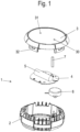
- a device 1 for detecting liquids comprises a tub-shaped housing 2 which has an upper opening which can be closed by a cover 3.
- a circuit board 4 is arranged in the housing 2 and has a capacitive sensor to detect a liquid running under the housing 2 in the event of a leak.
- at least two spaced-apart electrodes are attached to the underside of the circuit board 4, which are monitored by a control on the circuit board 4.
- a battery 5 is attached to the circuit board 4 for the power supply.
- the control on the circuit board 4 can communicate with a monitoring system that can monitor a large number of devices 1 simultaneously.
- corresponding transmitters and receivers are provided on the circuit board 4.
- An acoustic warning device 6 is also provided in the housing 2, which emits acoustic warning signals when a leak is detected.
- the warning device 6 can be encapsulated in order to be able to emit warning signals for as long as possible even if liquid enters the housing 2.
- the circuit board 4 also has an LED for a status display that emits light that is introduced into a rod-shaped light guide 7. The light is guided to a viewing window 30 on the cover 3 via the rod-shaped light guide 7 and is thus visible from the outside.
- the viewing window 30 can be formed by the front side of the light guide 7 so that the LED on the cover 3 is clearly visible.
- an actuating element 31, in particular a push button, is provided on the cover 3, by means of which the control on the circuit board 4 can be operated, for example to start up the device and to start the calibration process.
- Integrally formed locking elements 32 are provided on the cover 3 for fixing the cover 3 to the housing 2.
- the housing 2 with the cover 3 comprises a base 8, which can be placed at a distance from a base via foot elements 10, 11 and 12.
- the foot elements 10, 11 and 12 distributed over the circumference of the housing 2 have a different height, so that the base 8 is inclined to the horizontal on a horizontal, flat base, for example at an angle between 1° and 20°, in particular 2° to 10°.
- the foot elements 10 are higher than the foot elements 11, and the foot elements 11 are higher than the foot elements 12.
- the foot elements 10, 11 and 12 are web-shaped, but can also have a different geometry.
- An opening 9 is also provided on the bottom 8 of the housing 2 and is covered by the circuit board 4.
- the circuit board 4 is sealed and glued to the bottom 8 so that no liquid can enter the housing via the opening 9. Housing 2 can penetrate.
- the capacitive sensor 41 with at least two spaced-apart electrodes is provided.
- Flow channels 13 that are open at the bottom are formed on the base 8, through which air can flow out when liquid flows under the base 8.
- four flow channels 13 are provided, starting from the central opening 9, whereby the number of flow channels 13 can be freely selected by the expert.
- the flow channels 13 open into a ventilation channel 14 that ends at a certain height in the housing 2.
- the trough-shaped housing 2 is buoyant with the glued circuit board 4 and can thus float when the liquid level rises.
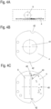
- the circuit board 4 is shown with the battery 5.
- the circuit board 4 comprises a light source 40 in the form of an LED, which emits light into the rod-shaped light guide 7 and can thus send out a status display via the viewing window 30.
- the capacitive sensor 41 with the electrodes is also provided on the underside of the circuit board 4 and is arranged in the area of the opening 9 of the housing 2.
- the circuit board 4 also has recesses 42 for exact positioning in the housing 2.
- Further electronic components 43 can be provided on the circuit board 4, in particular also operating elements such as push buttons for calibrating the sensor 41.
- Evaluation electronics can also be arranged on the circuit board 4, which determines in which state a warning message is issued.
- the housing 2 and optionally also the cover 3 are preferably made of an electrically conductive plastic which is also acid and alkali resistant.
- the device is used, for example, in collecting trays for the transport and storage of liquid hazardous substances.
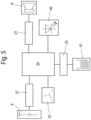
- FIG. 5 a block diagram of the circuit board 4 is shown.
- a central controller 20 is supplied with power via the battery 5, which provides a voltage of between 3 and 4 volts, for example.
- the battery 5 is connected to the controller 20 via a current and voltage limiter 21.
- a current and voltage limiter 21 is also arranged between the capacitive sensor 41 with the two electrodes and the controller 20 in order to minimize interference.
- the controller 20 can be operated via the actuating element 31, which is designed as a button or pushbutton, for example.
- the controller 20 is also connected to the lighting means 40 in the form of an LED, whereby several LEDs can optionally be provided for a more detailed status display.
- An acoustic warning device 6 is also arranged in the housing 2, which is optionally mounted at a distance from the base 8 in order to be able to issue warning messages for as long a period as possible even if liquid flows in.
- the warning device 6 is connected to the control unit 20 via a current and voltage limiter 21.
- the acoustic warning device 6 can be encapsulated.
- the actuating element 31 can be pressed for a certain period of time to initiate a calibration process.
- the controller 20 detects the conditions, temperature, humidity or other parameters and can adapt the threshold values for triggering to the respective environment. This enables the device 1 to be used in different environments, in particular in a steel tub or a plastic tub.
- the status display can then show the user that the device 1 has been activated.
Landscapes
- Physics & Mathematics (AREA)
- General Physics & Mathematics (AREA)
- Business, Economics & Management (AREA)
- Emergency Management (AREA)
- Investigating Or Analyzing Materials By The Use Of Electric Means (AREA)
- Examining Or Testing Airtightness (AREA)
Description
- Die vorliegende Erfindung betrifft eine Vorrichtung zur Detektion von Flüssigkeiten, insbesondere bei einer Leckage, mit einem Gehäuse und einer an oder in dem Gehäuse angeordneten Leiterplatte, an der ein kapazitiver Sensor mit mindestens einer Elektrode ausgebildet ist, wobei an einem Boden des Gehäuses eine Öffnung ausgebildet ist, die von der Leiterplatte überdeckt ist und die mindestens eine Elektrode des Sensors an einer Unterseite der Leiterplatte im Bereich der Öffnung angeordnet ist.
- Die
EP 478 950 A2 - In der
WO 2006/078105 A1 ist ein kapazitiver Leckagesensor offenbart, bei dem eine Leiterplatte mit dem Sensor in einem Gehäuse angeordnet ist, das nach der Montage der Leiterplatte mit Epoxidharz befüllt wird. Dadurch ist der Sensor von der Umgebung abgekapselt und die Erfassungsungenauigkeit wegen der Störeinflüsse zwischen dem Sensor und der zu detektierenden Flüssigkeit hoch. Gerade bei Flüssigkeiten mit einer niedrigen Dielektrizitätszahl, wie Öl, kann die Erfassung nur ungenau erfolgen. -
US 5,202,667 offenbart einen elektrischen Leckagedetektor, bei dem in einem rohrförmigen Gehäuse ein Kondensator angeordnet ist, der an eine Einheit zur Erfassung einer Leckage angeschlossen ist. Weitere Detektoren zur Erfassung einer Leckage zeigenUS2018/0275009 undDE 10 2015 119 251 . - Weitere Flüssigkeitssensoren im Stand der Technik sind bekannt aus
US8970385 undWO2019/061141 . - Es ist daher Aufgabe der vorliegenden Erfindung, eine Vorrichtung zur Detektion von Flüssigkeiten zu schaffen, die eine hohe Zuverlässigkeit und Genauigkeit bei der Erfassung besitzt.
- Diese Aufgabe wird mit einer Vorrichtung mit den Merkmalen des Anspruches 1 gelöst.
- Bei der erfindungsgemäßen Vorrichtung ist an einem Boden eines Gehäuses eine Öffnung ausgebildet, die von der Leiterplatte überdeckt ist, wobei die mindestens eine Elektrode des kapazitiven Sensors an einer Unterseite der Leiterplatte im Bereich der Öffnung angeordnet ist, so dass diese an der Unterseite frei zugänglich ist und mit einer zu detektierenden Flüssigkeit auch benetzt werden kann. Dadurch werden Störeinflüsse des Bodens auf den Sensor eliminiert. Dies erhöht die Genauigkeit und die Zuverlässigkeit bei der Detektion von Flüssigkeiten.
- Erfindungsgemäß sind die Leiterplatte und das Gehäuse abgedichtet miteinander verklebt. Dabei ist die Leiterplatte an einer Oberseite des Bodens des Gehäuses angeordnet. Gemäß der beanspruchten Erfindung ist die Leiterplatte in dem Gehäuse oberhalb des Bodens angeordnet und verklebt, so dass auf der Leiterplatte weitere elektronische Bauteile fixiert werden können.
- Für eine genaue Erfassung von Flüssigkeiten können an dem Sensor zwei bahnförmige Elektroden vorgesehen sein. Die bahnförmigen Elektroden können beispielsweise spiralförmig angeordnet sein und einen vorbestimmten Erfassungsbereich überdecken. Die von dem Sensor überwachte Fläche kann beispielsweise in einem Bereich zwischen 2 cm2 und 20 cm2 liegen.
- Mit dem kapazitiven Sensor lassen sich vorzugsweise auch Flüssigkeiten mit einer niedrigen Dielektrizitätszahl erfassen, die beispielsweise kleiner 2 ist. Während die Erfassung von Wasser aufgrund der hohen Dielektrizitätszahl einfach ist, lassen sich Öle und andere Flüssigkeiten deutlich schwerer erfassen.
- Das Gehäuse ist erfindungsgemäß mit der Leiterplatte wannenförmig ausgebildet und schwimmfähig. Dadurch kann bei schnellem Eintritt einer Flüssigkeit das Gehäuse aufschwimmen und für einen langen Zeitraum Signale abgeben.
- An der Oberseite der Leiterplatte sind vorzugsweise eine oder mehrere Batterien zur Stromversorgung und eine Steuerung vorgesehen. Die Steuerung kann dabei mit einem in dem Gehäuse angeordneten akustischen Warnmelder verbunden sein, der bei einer Leckage dauerhaft angeschaltet wird, um akustische Warnsignale abzugeben.
- In einer weiteren Ausgestaltung ist ein Boden des Gehäuses und die Leiterplatte durch Fußelemente geneigt zur Horizontalen ausgerichtet, beispielsweise mit einer Neigung zwischen 1° bis 20°, insbesondere 2° bis 10°. Dadurch können bei einem Einströmen von Flüssigkeit Luftblasen entlang der geneigten Fläche am Boden besser entweichen.
- An der Leiterplatte kann ferner mindestens ein Leuchtmittel, wie eine LED, für eine Statusanzeige vorgesehen sein, wobei das Licht über einen stabförmigen Lichtleiter zu einem Sichtfenster an einem Deckel geleitet wird. Dadurch lässt sich mit geringem Energieverbrauch eine Statusanzeige realisieren.
- Die Vorrichtung ist vorzugsweise in eine Überwachungsanlage eingebunden, wobei die Steuerung über einen Sender und einem Empfänger mit einer Steuerung der Überwachungsanlage kommunizieren kann. Dadurch können eine Vielzahl von Vorrichtungen zur Detektion von Flüssigkeiten miteinander in einer Überwachungsanlage gekoppelt werden. Die Vorrichtung kann insbesondere in einer Auffangwanne für flüssige Gefahrstoffe eingesetzt werden, um etwaige Leckagen zu detektieren.
- Die Erfindung wird nachfolgend anhand eines Ausführungsbeispiels mit Bezug auf die beigefügten Zeichnungen näher erläutert. Es zeigen:
- Figur 1
- eine perspektivische Explosionsdarstellung einer erfindungsgemäßen Vorrichtung zur Erfassung von Flüssigkeiten;
- Figuren 2 und 3
- zwei Ansichten der Vorrichtung der
Figur 1 in einer montierten Position; - Figuren 4A bis 4C
- mehrere Ansichten der Leiterplatte der Vorrichtung der Figur 1, und.
- Figur 5
- ein Blockschaltbild der Leiterplatte der
Figur 4 . - Eine Vorrichtung 1 zur Detektion von Flüssigkeiten umfasst ein wannenförmiges Gehäuse 2, das eine obere Öffnung aufweist, die über einen Deckel 3 verschließbar ist. In dem Gehäuse 2 ist eine Leiterplatte 4 angeordnet, die einen kapazitiven Sensor aufweist, um eine unter das Gehäuse 2 laufende Flüssigkeit im Fall einer Leckage zu erfassen. Hierfür sind an der Leiterplatte 4 an der Unterseite mindestens zwei beabstandete Elektroden aufgebracht, die über eine Steuerung an der Leiterplatte 4 überwacht werden. An der Leiterplatte 4 ist eine Batterie 5 zur Stromversorgung angebracht.
- Die Steuerung an der Leiterplatte 4 kann mit einer Überwachungsanlage kommunizieren, die eine Vielzahl von Vorrichtungen 1 gleichzeitig überwachen kann. Hierfür sind entsprechende Sender und Empfänger an der Leiterplatte 4 vorgesehen. In dem Gehäuse 2 ist zudem ist ein akustischer Warnmelder 6 vorgesehen, der bei Detektion einer Leckage akustische Warnsignale ausgibt. Der Warnmelder 6 kann gekapselt ausgebildet sein, um auch bei einem Eintreten von Flüssigkeit in das Gehäuse 2 möglichst lange Warnsignale abgeben zu können.
- An der Leiterplatte 4 ist ferner eine LED für eine Statusanzeige vorgesehen, die Licht emittiert, das in einen stabförmigen Lichtleiter 7 eingeleitet wird. Über den stabförmigen Lichtleiter 7 wird das Licht zu einem Sichtfenster 30 an dem Deckel 3 geleitet und ist somit von außen sichtbar. Das Sichtfenster 30 kann dabei durch die Stirnseite des Lichtleiters 7 gebildet sein, so dass die LED an dem Deckel 3 gut sichtbar ist. Zudem ist an dem Deckel 3 ein Betätigungselement 31, insbesondere ein Druckknopf, vorgesehen, mittels dem die Steuerung an der Leiterplatte 4 bedient werden kann, beispielsweise zur Inbetriebnahme der Vorrichtung und zum Starten des Kalibriervorgangs.
- An dem Deckel 3 sind integral ausgebildete Rastelemente 32 zur Fixierung des Deckels 3 an dem Gehäuse 2 vorgesehen.
- In den
Figuren 2 und 3 ist die Vorrichtung 1 in einer montierten Position gezeigt. Das Gehäuse 2 mit dem Deckel 3 umfasst einen Boden 8, der über Fußelemente 10, 11 und 12 beabstandet von einem Untergrund abstellbar ist. Die über den Umfang des Gehäuses 2 verteilten Fußelemente 10, 11 und 12 besitzen dabei eine unterschiedliche Höhe, so dass der Boden 8 bei einem horizontalen ebenen Untergrund geneigt zur Horizontalen ausgerichtet ist, beispielsweise in einem Winkel zwischen 1° bis 20°, insbesondere 2° bis 10°. Hierfür sind die Fußelemente 10 höher ausgebildet als die Fußelemente 11, und die Fußelemente 11 sind höher ausgebildet als die Fußelemente 12. Die Fußelemente 10, 11 und 12 sind stegförmig ausgebildet, können aber auch eine andere Geometrie besitzen. - An dem Boden 8 des Gehäuses 2 ist ferner eine Öffnung 9 ausgespart, die durch die Leiterplatte 4 überdeckt ist. Die Leiterplatte 4 ist dabei abgedichtet mit dem Boden 8 verklebt, so dass über die Öffnung 9 keine Flüssigkeit in das Gehäuse 2 eindringen kann. Im Bereich der Öffnung 9 ist der kapazitive Sensor 41 mit mindestens zwei beabstandet angeordneten Elektroden vorgesehen.
- An dem Boden 8 sind nach unten offene Strömungskanäle 13 ausgebildet, durch die Luft abströmen kann, wenn Flüssigkeit unter den Boden 8 strömt. In dem dargestellten Ausführungsbeispiel sind, ausgehend von der mittleren Öffnung 9, vier Strömungskanäle 13 vorgesehen, wobei die Anzahl der Strömungskanäle 13 vom Fachmann frei gewählt werden kann. Die Strömungskanäle 13 münden an einem Entlüftungskanal 14, der in einer gewissen Höhe in dem Gehäuse 2 endet. Das wannenförmige Gehäuse 2 ist mit der verklebten Leiterplatte 4 schwimmfähig und kann bei Ansteigen eines Flüssigkeitspegels somit aufschwimmen.
- In den
Figuren 4A bis 4C ist die Leiterplatte 4 mit der Batterie 5 gezeigt. Die Leiterplatte 4 umfasst ein Leuchtmittel 40 in Form einer LED, die Licht in den stabförmigen Lichtleiter 7 emittiert und somit eine Statusanzeige über das Sichtfenster 30 aussenden kann. An der Leiterplatte 4 ist ferner an der Unterseite der kapazitive Sensor 41 mit den Elektroden vorgesehen, der im Bereich der Öffnung 9 des Gehäuses 2 angeordnet ist. Die Leiterplatte 4 weist ferner Aussparungen 42 zur exakten Positionierung in dem Gehäuse 2 auf. An der Leiterplatte 4 können weitere elektronische Bauteile 43 vorgesehen sein, insbesondere auch Bedienelemente, wie Druckknöpfe, um den Sensor 41 zu kalibrieren. Auf der Leiterplatte 4 kann zudem eine Auswerteelektronik angeordnet sein, die festlegt, bei welchem Zustand eine Warnmeldung ausgegeben wird. Durch die Ausrichtung des Sensors 41 geneigt zur Horizontalen kann bei einem Einströmen von Flüssigkeit zuverlässig eine Benetzung des Sensors ohne Lufteinschlüsse erreicht werden, da die Luft an dem Boden 8 seitlich abströmen kann. - Das Gehäuse 2 und optional auch der Deckel 3 bestehen vorzugsweise aus einem elektrisch leitfähigen Kunststoff, der auch säure- und laugenbeständig ist.
- Die Vorrichtung wird beispielsweise in Auffangwannen für den Transport und die Lagerung von flüssigen Gefahrstoffen eingesetzt.
- In
Figur 5 ist ein Blockschaltbild der Leiterplatte 4 gezeigt. Eine zentrale Steuerung 20 wird über die Batterie 5 mit Strom versorgt, die beispielsweise eine Spannung zwischen 3 bis 4 Volt bereitstellt. Die Batterie 5 ist dabei über einen Strom- und Spannungsbegrenzer 21 mit der Steuerung 20 verbunden. Ferner ist zwischen dem kapazitiven Sensor 41 mit den beiden Elektroden und der Steuerung 20 ebenfalls ein Strom- und Spannungsbegrenzer 21 angeordnet, um Störeinflüsse zu minimieren. Die Steuerung 20 ist über das Betätigungselement 31 bedienbar, das beispielsweise als Taster oder Druckknopf ausgebildet ist. Ferner ist die Steuerung 20 mit dem Leuchtmittel 40 in Form einer LED verbunden, wobei optional auch mehrere LEDs für eine detailliertere Statusanzeige vorgesehen sein können. - In dem Gehäuse 2 ist ferner ein akustischer Warnmelder 6 angeordnet, der optional beabstandet von dem Boden 8 montiert ist, um auch bei einem Einströmen von Flüssigkeit für einen möglichst langen Zeitraum Warnmeldungen abgeben zu können. Der Warnmelder 6 ist über eine Strom- und Spannungsbegrenzung 21 mit der Steuerung 20 verbunden. Der akustische Warnmelder 6 kann dabei gekapselt ausgebildet sein.
- Zum Einschalten kann das Betätigungselement 31 für eine gewisse Zeitdauer gedrückt werden, damit ein Kalibriervorgang eingeleitet wird. Während des Kalibriervorganges erfasst die Steuerung 20 die Zustände, Temperatur, Luftfeuchte oder andere Parameter und kann die Schwellwerte zur Auslösung an die jeweilige Umgebung anpassen. Dies ermöglicht einen Einsatz der Vorrichtung 1 in unterschiedlichen Umgebungen, insbesondere in einer Stahlwanne oder einer Kunststoffwanne. Nach der Kalibrierung kann dann die Statusanzeige dem Benutzer die Aktivierung der Vorrichtung 1 anzeigen.
-
- 1
- Vorrichtung
- 2
- Gehäuse
- 3
- Deckel
- 4
- Leiterplatte
- 5
- Batterie
- 6
- Warnmelder
- 7
- Lichtleiter
- 8
- Boden
- 9
- Öffnung
- 10
- Fußelement
- 11
- Fußelement
- 12
- Fußelement
- 13
- Strömungskanal
- 14
- Entlüftungskanal
- 20
- Steuerung
- 21
- Strom- und Spannungsbegrenzer
- 30
- Sichtfenster
- 31
- Betätigungselement
- 32
- Rastelement
- 40
- Leuchtmittel
- 41
- Sensor
- 42
- Aussparung
- 43
- Bauteil
Claims (11)
- Vorrichtung (1) zur Detektion von Flüssigkeiten, insbesondere bei einer Leckage, mit einem Gehäuse (2) und einer in dem Gehäuse (2) angeordneten Leiterplatte (4), an der ein kapazitiver Sensor (41) mit mindestens einer Elektrode ausgebildet ist, wobei an einem Boden (8) des Gehäuses (2) eine Öffnung (9) ausgebildet ist, die von der Leiterplatte (4) überdeckt ist und die mindestens eine Elektrode (41) des Sensors an einer Unterseite der Leiterplatte (4) im Bereich der Öffnung (9) angeordnet ist, dadurch gekennzeichnet, dass die Leiterplatte (4) und das Gehäuse (2) abgedichtet mit einander verklebt sind, so dass über die Öffnung (9) keine Flüssigkeit in das Gehäuse (2) eindringen kann, und das Gehäuse (2) mit der Leiterplatte (4) wannenförmig ausgebildet und schwimmfähig ist.
- Vorrichtung nach Anspruch 1, dadurch gekennzeichnet, dass an dem Sensor (41) zwei bahnförmige Elektroden vorgesehen sind.
- Vorrichtung nach Anspruch 2, dadurch gekennzeichnet, dass die bahnförmigen Elektroden spiralförmig ausgebildet sind.
- Vorrichtung nach einem der vorhergehenden Ansprüche, dadurch gekennzeichnet, dass durch den kapazitiven Sensor (41) Flüssigkeiten mit einer Dielektrizitätskonstantzahl < 2 detektierbar sind.
- Vorrichtung nach einem der vorhergehenden Ansprüche, dadurch gekennzeichnet, dass an einer Oberseite der Leiterplatte (4) eine Batterie (5) und eine Steuerung (20) fixiert sind.
- Vorrichtung nach Anspruch 5, dadurch gekennzeichnet, dass die Steuerung (20) mit einem in dem Gehäuse (2) angeordneten akustischen Warnmelder (6) verbunden ist.
- Vorrichtung nach einem der vorhergehenden Ansprüche, dadurch gekennzeichnet, dass der Boden (8) des Gehäuses (2) und die Leiterplatte (4) durch Fußelemente (10, 11, 12) geneigt zur Horizontalen ausgerichtet sind, insbesondere in einem Winkel zwischen 1° bis 20°.
- Vorrichtung nach einem der vorhergehenden Ansprüche, dadurch gekennzeichnet, dass ein Taster zum Aktivieren eines Kalibriervorganges vorgesehen ist, bei dem eine Steuerung (20) Umgebungsparameter erfasst und die Schwellwerte zur Auslösung des Sensors (41) festsetzt.
- Vorrichtung nach einem der vorhergehenden Ansprüche, dadurch gekennzeichnet, dass auf der Leiterplatte (4) ein Leuchtmittel (40) für eine Statusanzeige vorgesehen ist, deren Licht über einen stabförmigen Lichtleiter (7) zu einem Sichtfenster (30) an einem Deckel (3) geleitet wird.
- Vorrichtung nach einem der vorhergehenden Ansprüche, dadurch gekennzeichnet, dass die Steuerung einen funktechnischen Sender und einen Empfänger umfasst, mittels der die Steuerung über eine datentechnische Infrastruktur, wie einer Daten-Cloud, kommunizieren kann.
- Auffangwanne für flüssige Gefahrstoffe, in der eine Vorrichtung nach einem der vorhergehenden Ansprüche angeordnet ist.
Applications Claiming Priority (2)
| Application Number | Priority Date | Filing Date | Title |
|---|---|---|---|
| DE202019104143.9U DE202019104143U1 (de) | 2019-07-26 | 2019-07-26 | Vorrichtung zur Detektion von Flüssigkeiten |
| PCT/EP2020/067358 WO2021018477A1 (de) | 2019-07-26 | 2020-06-22 | Vorrichtung zur detektion von flüssigkeiten |
Publications (4)
| Publication Number | Publication Date |
|---|---|
| EP4004429A1 EP4004429A1 (de) | 2022-06-01 |
| EP4004429C0 EP4004429C0 (de) | 2024-07-17 |
| EP4004429B1 true EP4004429B1 (de) | 2024-07-17 |
| EP4004429B8 EP4004429B8 (de) | 2024-08-28 |
Family
ID=71994464
Family Applications (1)
| Application Number | Title | Priority Date | Filing Date |
|---|---|---|---|
| EP20753289.6A Active EP4004429B8 (de) | 2019-07-26 | 2020-06-22 | Vorrichtung zur detektion von flüssigkeiten |
Country Status (3)
| Country | Link |
|---|---|
| EP (1) | EP4004429B8 (de) |
| DE (1) | DE202019104143U1 (de) |
| WO (1) | WO2021018477A1 (de) |
Families Citing this family (1)
| Publication number | Priority date | Publication date | Assignee | Title |
|---|---|---|---|---|
| WO2024134263A1 (en) | 2022-12-23 | 2024-06-27 | Intechfloor Sa | Sensor strip for liquid or humidity detection and applications and uses thereof |
Citations (2)
| Publication number | Priority date | Publication date | Assignee | Title |
|---|---|---|---|---|
| US8970385B1 (en) * | 2012-05-01 | 2015-03-03 | Gizmode, LLC | Moisture-detection apparatus and method |
| WO2019061141A1 (en) * | 2017-09-28 | 2019-04-04 | Ming Chuan Lee | WATER DETECTOR |
Family Cites Families (6)
| Publication number | Priority date | Publication date | Assignee | Title |
|---|---|---|---|---|
| DE4031522C1 (de) | 1990-10-05 | 1992-04-02 | Horst Dipl.-Ing. 2000 Hamburg De Krauleidies | |
| US5202667A (en) * | 1990-10-19 | 1993-04-13 | Monitoring Systems, Inc. | Electric leakage detector for underground storage tank systems |
| KR20060084160A (ko) * | 2005-01-19 | 2006-07-24 | 레시너코리아 주식회사 | 정전용량형 누수 감지센서 |
| DE102015119251A1 (de) * | 2015-11-09 | 2017-05-11 | Prv-Gesellschaft Für Vermögensverwaltung, Immobilien Und Dienstleistungen M.B.H. | Vorrichtung zur Überwachung eines Flüssigkeit enthaltenden Leitungssystems, beispielsweise auf Leckage oder unerwünschte Flüssigkeitsentnahme |
| CA3010340C (en) * | 2015-12-31 | 2021-06-15 | Delta Faucet Company | Water sensor |
| JP2018159646A (ja) * | 2017-03-23 | 2018-10-11 | 株式会社デンソーウェーブ | 漏水検出器 |
-
2019
- 2019-07-26 DE DE202019104143.9U patent/DE202019104143U1/de active Active
-
2020
- 2020-06-22 EP EP20753289.6A patent/EP4004429B8/de active Active
- 2020-06-22 WO PCT/EP2020/067358 patent/WO2021018477A1/de not_active Ceased
Patent Citations (2)
| Publication number | Priority date | Publication date | Assignee | Title |
|---|---|---|---|---|
| US8970385B1 (en) * | 2012-05-01 | 2015-03-03 | Gizmode, LLC | Moisture-detection apparatus and method |
| WO2019061141A1 (en) * | 2017-09-28 | 2019-04-04 | Ming Chuan Lee | WATER DETECTOR |
Also Published As
| Publication number | Publication date |
|---|---|
| EP4004429C0 (de) | 2024-07-17 |
| DE202019104143U1 (de) | 2020-10-27 |
| WO2021018477A1 (de) | 2021-02-04 |
| EP4004429B8 (de) | 2024-08-28 |
| EP4004429A1 (de) | 2022-06-01 |
Similar Documents
| Publication | Publication Date | Title |
|---|---|---|
| EP1701646B1 (de) | Geschirrspülmaschine mit einem system zur füllstandserkennung | |
| EP1348108A1 (de) | Verfahren und vorrichtung zum messen von pegelständen | |
| EP4004429B1 (de) | Vorrichtung zur detektion von flüssigkeiten | |
| DE3243839A1 (de) | Vorrichtung zur hoehenstandsmessung von fluessigkeiten in behaeltern, insbesondere fuellstandsanzeige fuer kraftfahrzeuge | |
| DE4013746A1 (de) | Fluessigkeitsdetektor | |
| EP1621863B1 (de) | Vorrichtung zur Erfassung einer Leckage | |
| EP4004515B1 (de) | Vorrichtung zur detektion von flüssigkeiten | |
| WO2017001112A1 (de) | Optische sensorvorrichtung mit zusätzlicher kapazitiver sensorik | |
| DE102005060363A1 (de) | Vorrichtung zur Ermittlung eines Füllstandes eines Flüssigkeitsbehälters eines Gerätes, insbesondere Hausgerätes sowie Füllstandssensor und Detektorschaltung hierfür | |
| EP2223177A2 (de) | Vorrichtung zur aufnahme einer flüssigkeit und vorrichtung zur positionsbestimmung eines schwimmerkörpers in einem behälter | |
| DE3014259A1 (de) | Vorrichtung zur anzeige geringer erschuetterungen der festen erdkruste | |
| WO2002012834A1 (de) | Vorrichtung zum messen/bestimmen einer physikalischen grösse eines mediums | |
| DE102016223759B3 (de) | Anordnung und Verfahren zur kapazitiven Füllstandsbestimmung | |
| CH705731A2 (de) | Vorrichtung und Verfahren zur kapazitiven Bestimmung eines Füllstandes eines Fluids in einem Behälter. | |
| DE102013015260A1 (de) | Heißgetränkesystem, Kapsel und Zubereitungsvorrichtung | |
| EP0510663B1 (de) | Vorrichtung zum Nachweis eines flüssigen oder gasförmigen Mediums | |
| DE602004011232T2 (de) | Füllstandssensor, der seine Betriebsenergie aus einem Anzeigeinstrument gewinnt | |
| DE102004019351A1 (de) | Geschirrspülmaschine mit einem System zur Füllstandserkennung | |
| DE102020116149A1 (de) | Ermittlung des füllstands in einem fluidbehälter | |
| EP1699343B1 (de) | GESCHIRRSPüLMASCHINE MIT EINEM SYSTEM ZUR FüLLSTANDERKENNUNG | |
| EP2694956B1 (de) | Thermoelektrische feuchtigkeitsdetektion | |
| JPH0714823Y2 (ja) | 液量検出器 | |
| DE102012000174A1 (de) | Vorrichtung zur Messung des Füllstandes einer elektrisch leitenden Flüssigkeit in einem Behälter | |
| DE10143198A1 (de) | Flüssigkeitsstandsanzeige in Pflazenbehältern | |
| DE102024102532A1 (de) | Sensoreinheit sowie Verfahren zur Füllstandsüberwachung |
Legal Events
| Date | Code | Title | Description |
|---|---|---|---|
| STAA | Information on the status of an ep patent application or granted ep patent |
Free format text: STATUS: UNKNOWN |
|
| STAA | Information on the status of an ep patent application or granted ep patent |
Free format text: STATUS: THE INTERNATIONAL PUBLICATION HAS BEEN MADE |
|
| PUAI | Public reference made under article 153(3) epc to a published international application that has entered the european phase |
Free format text: ORIGINAL CODE: 0009012 |
|
| STAA | Information on the status of an ep patent application or granted ep patent |
Free format text: STATUS: REQUEST FOR EXAMINATION WAS MADE |
|
| 17P | Request for examination filed |
Effective date: 20211110 |
|
| AK | Designated contracting states |
Kind code of ref document: A1 Designated state(s): AL AT BE BG CH CY CZ DE DK EE ES FI FR GB GR HR HU IE IS IT LI LT LU LV MC MK MT NL NO PL PT RO RS SE SI SK SM TR |
|
| DAV | Request for validation of the european patent (deleted) | ||
| DAX | Request for extension of the european patent (deleted) | ||
| GRAP | Despatch of communication of intention to grant a patent |
Free format text: ORIGINAL CODE: EPIDOSNIGR1 |
|
| STAA | Information on the status of an ep patent application or granted ep patent |
Free format text: STATUS: GRANT OF PATENT IS INTENDED |
|
| INTG | Intention to grant announced |
Effective date: 20240315 |
|
| GRAS | Grant fee paid |
Free format text: ORIGINAL CODE: EPIDOSNIGR3 |
|
| GRAA | (expected) grant |
Free format text: ORIGINAL CODE: 0009210 |
|
| STAA | Information on the status of an ep patent application or granted ep patent |
Free format text: STATUS: THE PATENT HAS BEEN GRANTED |
|
| AK | Designated contracting states |
Kind code of ref document: B1 Designated state(s): AL AT BE BG CH CY CZ DE DK EE ES FI FR GB GR HR HU IE IS IT LI LT LU LV MC MK MT NL NO PL PT RO RS SE SI SK SM TR |
|
| REG | Reference to a national code |
Ref country code: DE Ref legal event code: R081 Ref document number: 502020008610 Country of ref document: DE Owner name: DENIOS SE, DE Free format text: FORMER OWNER: ANMELDERANGABEN UNKLAR / UNVOLLSTAENDIG, 80297 MUENCHEN, DE |
|
| REG | Reference to a national code |
Ref country code: CH Ref legal event code: PK Free format text: BERICHTIGUNG B8 Ref country code: CH Ref legal event code: EP |
|
| REG | Reference to a national code |
Ref country code: DE Ref legal event code: R096 Ref document number: 502020008610 Country of ref document: DE |
|
| RAP4 | Party data changed (patent owner data changed or rights of a patent transferred) |
Owner name: DENIOS SE |
|
| REG | Reference to a national code |
Ref country code: IE Ref legal event code: FG4D Free format text: LANGUAGE OF EP DOCUMENT: GERMAN |
|
| U01 | Request for unitary effect filed |
Effective date: 20240814 |
|
| U07 | Unitary effect registered |
Designated state(s): AT BE BG DE DK EE FI FR IT LT LU LV MT NL PT RO SE SI Effective date: 20240906 |
|
| PG25 | Lapsed in a contracting state [announced via postgrant information from national office to epo] |
Ref country code: NO Free format text: LAPSE BECAUSE OF FAILURE TO SUBMIT A TRANSLATION OF THE DESCRIPTION OR TO PAY THE FEE WITHIN THE PRESCRIBED TIME-LIMIT Effective date: 20241017 |
|
| PG25 | Lapsed in a contracting state [announced via postgrant information from national office to epo] |
Ref country code: PL Free format text: LAPSE BECAUSE OF FAILURE TO SUBMIT A TRANSLATION OF THE DESCRIPTION OR TO PAY THE FEE WITHIN THE PRESCRIBED TIME-LIMIT Effective date: 20240717 Ref country code: GR Free format text: LAPSE BECAUSE OF FAILURE TO SUBMIT A TRANSLATION OF THE DESCRIPTION OR TO PAY THE FEE WITHIN THE PRESCRIBED TIME-LIMIT Effective date: 20241018 |
|
| PG25 | Lapsed in a contracting state [announced via postgrant information from national office to epo] |
Ref country code: IS Free format text: LAPSE BECAUSE OF FAILURE TO SUBMIT A TRANSLATION OF THE DESCRIPTION OR TO PAY THE FEE WITHIN THE PRESCRIBED TIME-LIMIT Effective date: 20241117 |
|
| PG25 | Lapsed in a contracting state [announced via postgrant information from national office to epo] |
Ref country code: HR Free format text: LAPSE BECAUSE OF FAILURE TO SUBMIT A TRANSLATION OF THE DESCRIPTION OR TO PAY THE FEE WITHIN THE PRESCRIBED TIME-LIMIT Effective date: 20240717 |
|
| PG25 | Lapsed in a contracting state [announced via postgrant information from national office to epo] |
Ref country code: RS Free format text: LAPSE BECAUSE OF FAILURE TO SUBMIT A TRANSLATION OF THE DESCRIPTION OR TO PAY THE FEE WITHIN THE PRESCRIBED TIME-LIMIT Effective date: 20241017 Ref country code: ES Free format text: LAPSE BECAUSE OF FAILURE TO SUBMIT A TRANSLATION OF THE DESCRIPTION OR TO PAY THE FEE WITHIN THE PRESCRIBED TIME-LIMIT Effective date: 20240717 |
|
| PG25 | Lapsed in a contracting state [announced via postgrant information from national office to epo] |
Ref country code: RS Free format text: LAPSE BECAUSE OF FAILURE TO SUBMIT A TRANSLATION OF THE DESCRIPTION OR TO PAY THE FEE WITHIN THE PRESCRIBED TIME-LIMIT Effective date: 20241017 Ref country code: PL Free format text: LAPSE BECAUSE OF FAILURE TO SUBMIT A TRANSLATION OF THE DESCRIPTION OR TO PAY THE FEE WITHIN THE PRESCRIBED TIME-LIMIT Effective date: 20240717 Ref country code: NO Free format text: LAPSE BECAUSE OF FAILURE TO SUBMIT A TRANSLATION OF THE DESCRIPTION OR TO PAY THE FEE WITHIN THE PRESCRIBED TIME-LIMIT Effective date: 20241017 Ref country code: IS Free format text: LAPSE BECAUSE OF FAILURE TO SUBMIT A TRANSLATION OF THE DESCRIPTION OR TO PAY THE FEE WITHIN THE PRESCRIBED TIME-LIMIT Effective date: 20241117 Ref country code: HR Free format text: LAPSE BECAUSE OF FAILURE TO SUBMIT A TRANSLATION OF THE DESCRIPTION OR TO PAY THE FEE WITHIN THE PRESCRIBED TIME-LIMIT Effective date: 20240717 Ref country code: GR Free format text: LAPSE BECAUSE OF FAILURE TO SUBMIT A TRANSLATION OF THE DESCRIPTION OR TO PAY THE FEE WITHIN THE PRESCRIBED TIME-LIMIT Effective date: 20241018 Ref country code: ES Free format text: LAPSE BECAUSE OF FAILURE TO SUBMIT A TRANSLATION OF THE DESCRIPTION OR TO PAY THE FEE WITHIN THE PRESCRIBED TIME-LIMIT Effective date: 20240717 |
|
| PG25 | Lapsed in a contracting state [announced via postgrant information from national office to epo] |
Ref country code: SM Free format text: LAPSE BECAUSE OF FAILURE TO SUBMIT A TRANSLATION OF THE DESCRIPTION OR TO PAY THE FEE WITHIN THE PRESCRIBED TIME-LIMIT Effective date: 20240717 |
|
| PG25 | Lapsed in a contracting state [announced via postgrant information from national office to epo] |
Ref country code: CZ Free format text: LAPSE BECAUSE OF FAILURE TO SUBMIT A TRANSLATION OF THE DESCRIPTION OR TO PAY THE FEE WITHIN THE PRESCRIBED TIME-LIMIT Effective date: 20240717 |
|
| PG25 | Lapsed in a contracting state [announced via postgrant information from national office to epo] |
Ref country code: SK Free format text: LAPSE BECAUSE OF FAILURE TO SUBMIT A TRANSLATION OF THE DESCRIPTION OR TO PAY THE FEE WITHIN THE PRESCRIBED TIME-LIMIT Effective date: 20240717 |
|
| U20 | Renewal fee for the european patent with unitary effect paid |
Year of fee payment: 6 Effective date: 20250401 |
|
| PLBE | No opposition filed within time limit |
Free format text: ORIGINAL CODE: 0009261 |
|
| STAA | Information on the status of an ep patent application or granted ep patent |
Free format text: STATUS: NO OPPOSITION FILED WITHIN TIME LIMIT |
|
| 26N | No opposition filed |
Effective date: 20250422 |
|
| REG | Reference to a national code |
Ref country code: CH Ref legal event code: H13 Free format text: ST27 STATUS EVENT CODE: U-0-0-H10-H13 (AS PROVIDED BY THE NATIONAL OFFICE) Effective date: 20260127 |
|
| PG25 | Lapsed in a contracting state [announced via postgrant information from national office to epo] |
Ref country code: MC Free format text: LAPSE BECAUSE OF FAILURE TO SUBMIT A TRANSLATION OF THE DESCRIPTION OR TO PAY THE FEE WITHIN THE PRESCRIBED TIME-LIMIT Effective date: 20240717 |
|
| GBPC | Gb: european patent ceased through non-payment of renewal fee |
Effective date: 20250622 |
|
| PG25 | Lapsed in a contracting state [announced via postgrant information from national office to epo] |
Ref country code: GB Free format text: LAPSE BECAUSE OF NON-PAYMENT OF DUE FEES Effective date: 20250622 |
|
| PG25 | Lapsed in a contracting state [announced via postgrant information from national office to epo] |
Ref country code: IE Free format text: LAPSE BECAUSE OF NON-PAYMENT OF DUE FEES Effective date: 20250622 |
|
| PG25 | Lapsed in a contracting state [announced via postgrant information from national office to epo] |
Ref country code: CH Free format text: LAPSE BECAUSE OF NON-PAYMENT OF DUE FEES Effective date: 20250630 |