EP4004429B1 - Dispositif de détection de liquides - Google Patents
Dispositif de détection de liquides Download PDFInfo
- Publication number
- EP4004429B1 EP4004429B1 EP20753289.6A EP20753289A EP4004429B1 EP 4004429 B1 EP4004429 B1 EP 4004429B1 EP 20753289 A EP20753289 A EP 20753289A EP 4004429 B1 EP4004429 B1 EP 4004429B1
- Authority
- EP
- European Patent Office
- Prior art keywords
- circuit board
- housing
- printed circuit
- sensor
- controller
- Prior art date
- Legal status (The legal status is an assumption and is not a legal conclusion. Google has not performed a legal analysis and makes no representation as to the accuracy of the status listed.)
- Active
Links
Images

Classifications
-
- G—PHYSICS
- G01—MEASURING; TESTING
- G01M—TESTING STATIC OR DYNAMIC BALANCE OF MACHINES OR STRUCTURES; TESTING OF STRUCTURES OR APPARATUS, NOT OTHERWISE PROVIDED FOR
- G01M3/00—Investigating fluid-tightness of structures
- G01M3/02—Investigating fluid-tightness of structures by using fluid or vacuum
- G01M3/04—Investigating fluid-tightness of structures by using fluid or vacuum by detecting the presence of fluid at the leakage point
- G01M3/16—Investigating fluid-tightness of structures by using fluid or vacuum by detecting the presence of fluid at the leakage point using electric detection means
-
- G—PHYSICS
- G08—SIGNALLING
- G08B—SIGNALLING SYSTEMS, e.g. PERSONAL CALLING SYSTEMS; ORDER TELEGRAPHS; ALARM SYSTEMS
- G08B21/00—Alarms responsive to a single specified undesired or abnormal condition and not otherwise provided for
- G08B21/18—Status alarms
- G08B21/20—Status alarms responsive to moisture
Definitions
- the present invention relates to a device for detecting liquids, in particular in the event of a leak, with a housing and a circuit board arranged on or in the housing, on which a capacitive sensor with at least one electrode is formed, wherein an opening is formed on a bottom of the housing, which is covered by the circuit board and the at least one electrode of the sensor is arranged on an underside of the circuit board in the region of the opening.
- the EP 478 950 A2 discloses a device for detecting and reporting liquids, in which a protruding pair of electrodes is provided on the underside of a housing for conductive detection of a liquid.
- a sensor device is provided for optical detection of the liquid.
- the cable-connected device is comparatively complex to manufacture, and problems can also arise with regard to sealing if a large amount of liquid flows under the device.
- WO 2006/078105 A1 A capacitive leakage sensor is disclosed in which a circuit board with the sensor is arranged in a housing that is filled with epoxy resin after the circuit board has been installed. This encapsulates the sensor from the environment and the detection inaccuracy is high due to the interference between the sensor and the liquid to be detected. Especially with liquids with a low dielectric constant, such as oil, detection can only be carried out inaccurately.
- US$5,202,667 discloses an electrical leak detector in which a capacitor is arranged in a tubular housing and is connected to a unit for detecting a leak.
- Other detectors for detecting a leak show US2018/0275009 and EN 10 2015 119 251 .
- an opening is formed on a bottom of a housing, which opening is covered by the circuit board, wherein the at least one electrode of the capacitive sensor is on an underside of the circuit board is arranged in the area of the opening so that it is freely accessible from the bottom and can also be wetted with a liquid to be detected.
- the circuit board and the housing are glued together in a sealed manner.
- the circuit board is arranged on an upper side of the base of the housing.
- the circuit board is arranged in the housing above the base and glued so that further electronic components can be fixed to the circuit board.
- two track-shaped electrodes can be provided on the sensor.
- the track-shaped electrodes can, for example, be arranged in a spiral shape and cover a predetermined detection area.
- the area monitored by the sensor can, for example, be in a range between 2 cm 2 and 20 cm 2 .
- the capacitive sensor can also be used to detect liquids with a low dielectric constant, for example less than 2. While water is easy to detect due to its high dielectric constant, oils and other liquids are much more difficult to detect.
- the housing is designed with the circuit board in a trough shape and is floatable. This means that if a liquid enters quickly, the housing can float and emit signals for a long period of time.
- One or more batteries for power supply and a control unit are preferably provided on the top of the circuit board.
- the control unit can be connected to an acoustic warning device arranged in the housing, which is permanently switched on in the event of a leak in order to emit acoustic warning signals.
- a base of the housing and the circuit board are aligned at an angle to the horizontal by means of foot elements, for example with an inclination between 1° and 20°, in particular 2° and 10°. This allows When liquid flows in, air bubbles escape more easily along the inclined surface on the floor.
- At least one light source such as an LED
- the device is preferably integrated into a monitoring system, whereby the control can communicate with a control of the monitoring system via a transmitter and a receiver.
- This allows a large number of devices for detecting liquids to be coupled with one another in a monitoring system.
- the device can be used in particular in a collecting tray for liquid hazardous substances in order to detect any leaks.
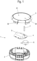
- a device 1 for detecting liquids comprises a tub-shaped housing 2 which has an upper opening which can be closed by a cover 3.
- a circuit board 4 is arranged in the housing 2 and has a capacitive sensor to detect a liquid running under the housing 2 in the event of a leak.
- at least two spaced-apart electrodes are attached to the underside of the circuit board 4, which are monitored by a control on the circuit board 4.
- a battery 5 is attached to the circuit board 4 for the power supply.
- the control on the circuit board 4 can communicate with a monitoring system that can monitor a large number of devices 1 simultaneously.
- corresponding transmitters and receivers are provided on the circuit board 4.
- An acoustic warning device 6 is also provided in the housing 2, which emits acoustic warning signals when a leak is detected.
- the warning device 6 can be encapsulated in order to be able to emit warning signals for as long as possible even if liquid enters the housing 2.
- the circuit board 4 also has an LED for a status display that emits light that is introduced into a rod-shaped light guide 7. The light is guided to a viewing window 30 on the cover 3 via the rod-shaped light guide 7 and is thus visible from the outside.
- the viewing window 30 can be formed by the front side of the light guide 7 so that the LED on the cover 3 is clearly visible.
- an actuating element 31, in particular a push button, is provided on the cover 3, by means of which the control on the circuit board 4 can be operated, for example to start up the device and to start the calibration process.
- Integrally formed locking elements 32 are provided on the cover 3 for fixing the cover 3 to the housing 2.
- the housing 2 with the cover 3 comprises a base 8, which can be placed at a distance from a base via foot elements 10, 11 and 12.
- the foot elements 10, 11 and 12 distributed over the circumference of the housing 2 have a different height, so that the base 8 is inclined to the horizontal on a horizontal, flat base, for example at an angle between 1° and 20°, in particular 2° to 10°.
- the foot elements 10 are higher than the foot elements 11, and the foot elements 11 are higher than the foot elements 12.
- the foot elements 10, 11 and 12 are web-shaped, but can also have a different geometry.
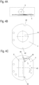
- An opening 9 is also provided on the bottom 8 of the housing 2 and is covered by the circuit board 4.
- the circuit board 4 is sealed and glued to the bottom 8 so that no liquid can enter the housing via the opening 9. Housing 2 can penetrate.
- the capacitive sensor 41 with at least two spaced-apart electrodes is provided.
- Flow channels 13 that are open at the bottom are formed on the base 8, through which air can flow out when liquid flows under the base 8.
- four flow channels 13 are provided, starting from the central opening 9, whereby the number of flow channels 13 can be freely selected by the expert.
- the flow channels 13 open into a ventilation channel 14 that ends at a certain height in the housing 2.
- the trough-shaped housing 2 is buoyant with the glued circuit board 4 and can thus float when the liquid level rises.
- the circuit board 4 is shown with the battery 5.
- the circuit board 4 comprises a light source 40 in the form of an LED, which emits light into the rod-shaped light guide 7 and can thus send out a status display via the viewing window 30.
- the capacitive sensor 41 with the electrodes is also provided on the underside of the circuit board 4 and is arranged in the area of the opening 9 of the housing 2.
- the circuit board 4 also has recesses 42 for exact positioning in the housing 2.
- Further electronic components 43 can be provided on the circuit board 4, in particular also operating elements such as push buttons for calibrating the sensor 41.
- Evaluation electronics can also be arranged on the circuit board 4, which determines in which state a warning message is issued.
- the housing 2 and optionally also the cover 3 are preferably made of an electrically conductive plastic which is also acid and alkali resistant.
- the device is used, for example, in collecting trays for the transport and storage of liquid hazardous substances.
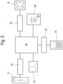
- FIG. 5 a block diagram of the circuit board 4 is shown.
- a central controller 20 is supplied with power via the battery 5, which provides a voltage of between 3 and 4 volts, for example.
- the battery 5 is connected to the controller 20 via a current and voltage limiter 21.
- a current and voltage limiter 21 is also arranged between the capacitive sensor 41 with the two electrodes and the controller 20 in order to minimize interference.
- the controller 20 can be operated via the actuating element 31, which is designed as a button or pushbutton, for example.
- the controller 20 is also connected to the lighting means 40 in the form of an LED, whereby several LEDs can optionally be provided for a more detailed status display.
- An acoustic warning device 6 is also arranged in the housing 2, which is optionally mounted at a distance from the base 8 in order to be able to issue warning messages for as long a period as possible even if liquid flows in.
- the warning device 6 is connected to the control unit 20 via a current and voltage limiter 21.
- the acoustic warning device 6 can be encapsulated.
- the actuating element 31 can be pressed for a certain period of time to initiate a calibration process.
- the controller 20 detects the conditions, temperature, humidity or other parameters and can adapt the threshold values for triggering to the respective environment. This enables the device 1 to be used in different environments, in particular in a steel tub or a plastic tub.
- the status display can then show the user that the device 1 has been activated.
Landscapes
- Physics & Mathematics (AREA)
- General Physics & Mathematics (AREA)
- Business, Economics & Management (AREA)
- Emergency Management (AREA)
- Investigating Or Analyzing Materials By The Use Of Electric Means (AREA)
- Examining Or Testing Airtightness (AREA)
Claims (11)
- Dispositif (1) pour la détection de liquides, en particulier lors d'une fuite, avec un boîtier (2) et une carte de circuits (4) disposée dans le boîtier (2), sur laquelle est formé un capteur capacitif (41) muni d'au moins une électrode, dans lequel un fond (8) du boîtier (2) comporte une ouverture (9) qui est couverte par la carte de circuits (4) et l'au moins une électrode (41) du capteur est disposée sur une face inférieure de la carte de circuits (4) dans la région de l'ouverture (9), caractérisé en ce que la carte de circuits (4) et le boîtier (2) sont collés l'une à l'autre de façon étanche de sorte qu'aucun liquide ne peut pénétrer dans le boîtier (2) par l'ouverture (9), et le boîtier (2) muni de la carte de circuits (4) est en forme de bac et capable de flotter.
- Dispositif selon la revendication 1, caractérisé en ce que deux électrodes en forme de piste conductrice sont prévues sur le capteur (41).
- Dispositif selon la revendication 2, caractérisé en ce que les électrodes en forme de piste conductrice sont conformées en spirale.
- Dispositif selon l'une des revendications précédentes, caractérisé en ce que le capteur capacitif (41) peut détecter des liquides ayant une constante diélectrique inférieure à 2.
- Dispositif selon l'une des revendications précédentes, caractérisé en ce qu'une pile (5) et une unité de commande (20) sont fixées sur une face supérieure de la carte de circuits (4).
- Dispositif selon la revendication 5, caractérisé en ce que l'unité de commande (20) communique avec un émetteur d'alarme acoustique (6) disposé dans le boîtier (2).
- Dispositif selon l'une des revendications précédentes, caractérisé en ce que le fond (8) du boîtier (2) et la carte de circuits (4) sont inclinés par rapport à l'horizontale par des éléments formant des pieds (10, 11, 12), en particulier selon un angle compris entre 1° et 20°.
- Dispositif selon l'une des revendications précédentes, caractérisé en ce qu'un bouton est prévu pour activer une opération d'étalonnage au cours de laquelle une unité de commande (20) acquiert des paramètres d'environnement et fixe les valeurs de seuil de déclenchement du capteur (41).
- Dispositif selon l'une des revendications précédentes, caractérisé en ce qu'une lampe (40) est prévue sur la carte de circuits (4) pour servir de témoins d'état, dont la lumière est transmise via un guide d'ondes lumineuses (7) en forme de barre jusqu'à une fenêtre (30) d'un couvercle (3).
- Dispositif selon l'une des revendications précédentes, caractérisé en ce que l'unité de commande comprend un émetteur de radio et un récepteur au moyen desquels l'unité de commande peut communiquer avec une infrastructure de données telle qu'un nuage de données.
- Bac collecteur pour matières dangereuses liquides, dans lequel est disposé un dispositif selon l'une des revendications précédentes.
Applications Claiming Priority (2)
| Application Number | Priority Date | Filing Date | Title |
|---|---|---|---|
| DE202019104143.9U DE202019104143U1 (de) | 2019-07-26 | 2019-07-26 | Vorrichtung zur Detektion von Flüssigkeiten |
| PCT/EP2020/067358 WO2021018477A1 (fr) | 2019-07-26 | 2020-06-22 | Dispositif de détection de liquides |
Publications (4)
| Publication Number | Publication Date |
|---|---|
| EP4004429A1 EP4004429A1 (fr) | 2022-06-01 |
| EP4004429C0 EP4004429C0 (fr) | 2024-07-17 |
| EP4004429B1 true EP4004429B1 (fr) | 2024-07-17 |
| EP4004429B8 EP4004429B8 (fr) | 2024-08-28 |
Family
ID=71994464
Family Applications (1)
| Application Number | Title | Priority Date | Filing Date |
|---|---|---|---|
| EP20753289.6A Active EP4004429B8 (fr) | 2019-07-26 | 2020-06-22 | Dispositif de détection de liquides |
Country Status (3)
| Country | Link |
|---|---|
| EP (1) | EP4004429B8 (fr) |
| DE (1) | DE202019104143U1 (fr) |
| WO (1) | WO2021018477A1 (fr) |
Families Citing this family (1)
| Publication number | Priority date | Publication date | Assignee | Title |
|---|---|---|---|---|
| WO2024134263A1 (fr) | 2022-12-23 | 2024-06-27 | Intechfloor Sa | Bande de capteur pour détection de liquide ou d'humidité et applications et utilisations associées |
Citations (2)
| Publication number | Priority date | Publication date | Assignee | Title |
|---|---|---|---|---|
| US8970385B1 (en) * | 2012-05-01 | 2015-03-03 | Gizmode, LLC | Moisture-detection apparatus and method |
| WO2019061141A1 (fr) * | 2017-09-28 | 2019-04-04 | Ming Chuan Lee | Détecteur d'eau |
Family Cites Families (6)
| Publication number | Priority date | Publication date | Assignee | Title |
|---|---|---|---|---|
| DE4031522C1 (fr) | 1990-10-05 | 1992-04-02 | Horst Dipl.-Ing. 2000 Hamburg De Krauleidies | |
| US5202667A (en) * | 1990-10-19 | 1993-04-13 | Monitoring Systems, Inc. | Electric leakage detector for underground storage tank systems |
| KR20060084160A (ko) * | 2005-01-19 | 2006-07-24 | 레시너코리아 주식회사 | 정전용량형 누수 감지센서 |
| DE102015119251A1 (de) * | 2015-11-09 | 2017-05-11 | Prv-Gesellschaft Für Vermögensverwaltung, Immobilien Und Dienstleistungen M.B.H. | Vorrichtung zur Überwachung eines Flüssigkeit enthaltenden Leitungssystems, beispielsweise auf Leckage oder unerwünschte Flüssigkeitsentnahme |
| CA3010340C (fr) * | 2015-12-31 | 2021-06-15 | Delta Faucet Company | Capteur d'eau |
| JP2018159646A (ja) * | 2017-03-23 | 2018-10-11 | 株式会社デンソーウェーブ | 漏水検出器 |
-
2019
- 2019-07-26 DE DE202019104143.9U patent/DE202019104143U1/de active Active
-
2020
- 2020-06-22 EP EP20753289.6A patent/EP4004429B8/fr active Active
- 2020-06-22 WO PCT/EP2020/067358 patent/WO2021018477A1/fr not_active Ceased
Patent Citations (2)
| Publication number | Priority date | Publication date | Assignee | Title |
|---|---|---|---|---|
| US8970385B1 (en) * | 2012-05-01 | 2015-03-03 | Gizmode, LLC | Moisture-detection apparatus and method |
| WO2019061141A1 (fr) * | 2017-09-28 | 2019-04-04 | Ming Chuan Lee | Détecteur d'eau |
Also Published As
| Publication number | Publication date |
|---|---|
| EP4004429C0 (fr) | 2024-07-17 |
| DE202019104143U1 (de) | 2020-10-27 |
| WO2021018477A1 (fr) | 2021-02-04 |
| EP4004429B8 (fr) | 2024-08-28 |
| EP4004429A1 (fr) | 2022-06-01 |
Similar Documents
| Publication | Publication Date | Title |
|---|---|---|
| EP1701646B1 (fr) | Lave-vaisselle pourvu d'un systeme de detection de niveau | |
| EP1348108A1 (fr) | Procede et dispositif de mesure de niveaux | |
| EP4004429B1 (fr) | Dispositif de détection de liquides | |
| DE3243839A1 (de) | Vorrichtung zur hoehenstandsmessung von fluessigkeiten in behaeltern, insbesondere fuellstandsanzeige fuer kraftfahrzeuge | |
| DE4013746A1 (de) | Fluessigkeitsdetektor | |
| EP1621863B1 (fr) | Dispositif de détection d'une fuite | |
| EP4004515B1 (fr) | Dispositif de détection de liquides | |
| WO2017001112A1 (fr) | Dispositif de détection optique avec capteurs capacitifs supplémentaires | |
| DE102005060363A1 (de) | Vorrichtung zur Ermittlung eines Füllstandes eines Flüssigkeitsbehälters eines Gerätes, insbesondere Hausgerätes sowie Füllstandssensor und Detektorschaltung hierfür | |
| EP2223177A2 (fr) | Dispositif de reception d'un liquide et dispositif de determination de la position d'un flotteur dans un contenant | |
| DE3014259A1 (de) | Vorrichtung zur anzeige geringer erschuetterungen der festen erdkruste | |
| WO2002012834A1 (fr) | Dispositif pour mesurer/determiner une grandeur physique d'un support | |
| DE102016223759B3 (de) | Anordnung und Verfahren zur kapazitiven Füllstandsbestimmung | |
| CH705731A2 (de) | Vorrichtung und Verfahren zur kapazitiven Bestimmung eines Füllstandes eines Fluids in einem Behälter. | |
| DE102013015260A1 (de) | Heißgetränkesystem, Kapsel und Zubereitungsvorrichtung | |
| EP0510663B1 (fr) | Dispositif pour la détection d'une matière liquide ou gazeuse | |
| DE602004011232T2 (de) | Füllstandssensor, der seine Betriebsenergie aus einem Anzeigeinstrument gewinnt | |
| DE102004019351A1 (de) | Geschirrspülmaschine mit einem System zur Füllstandserkennung | |
| DE102020116149A1 (de) | Ermittlung des füllstands in einem fluidbehälter | |
| EP1699343B1 (fr) | Lave-vaisselle pourvu d'un systeme de detection de niveau | |
| EP2694956B1 (fr) | Détection thermoélectrique d'humidité | |
| JPH0714823Y2 (ja) | 液量検出器 | |
| DE102012000174A1 (de) | Vorrichtung zur Messung des Füllstandes einer elektrisch leitenden Flüssigkeit in einem Behälter | |
| DE10143198A1 (de) | Flüssigkeitsstandsanzeige in Pflazenbehältern | |
| DE102024102532A1 (de) | Sensoreinheit sowie Verfahren zur Füllstandsüberwachung |
Legal Events
| Date | Code | Title | Description |
|---|---|---|---|
| STAA | Information on the status of an ep patent application or granted ep patent |
Free format text: STATUS: UNKNOWN |
|
| STAA | Information on the status of an ep patent application or granted ep patent |
Free format text: STATUS: THE INTERNATIONAL PUBLICATION HAS BEEN MADE |
|
| PUAI | Public reference made under article 153(3) epc to a published international application that has entered the european phase |
Free format text: ORIGINAL CODE: 0009012 |
|
| STAA | Information on the status of an ep patent application or granted ep patent |
Free format text: STATUS: REQUEST FOR EXAMINATION WAS MADE |
|
| 17P | Request for examination filed |
Effective date: 20211110 |
|
| AK | Designated contracting states |
Kind code of ref document: A1 Designated state(s): AL AT BE BG CH CY CZ DE DK EE ES FI FR GB GR HR HU IE IS IT LI LT LU LV MC MK MT NL NO PL PT RO RS SE SI SK SM TR |
|
| DAV | Request for validation of the european patent (deleted) | ||
| DAX | Request for extension of the european patent (deleted) | ||
| GRAP | Despatch of communication of intention to grant a patent |
Free format text: ORIGINAL CODE: EPIDOSNIGR1 |
|
| STAA | Information on the status of an ep patent application or granted ep patent |
Free format text: STATUS: GRANT OF PATENT IS INTENDED |
|
| INTG | Intention to grant announced |
Effective date: 20240315 |
|
| GRAS | Grant fee paid |
Free format text: ORIGINAL CODE: EPIDOSNIGR3 |
|
| GRAA | (expected) grant |
Free format text: ORIGINAL CODE: 0009210 |
|
| STAA | Information on the status of an ep patent application or granted ep patent |
Free format text: STATUS: THE PATENT HAS BEEN GRANTED |
|
| AK | Designated contracting states |
Kind code of ref document: B1 Designated state(s): AL AT BE BG CH CY CZ DE DK EE ES FI FR GB GR HR HU IE IS IT LI LT LU LV MC MK MT NL NO PL PT RO RS SE SI SK SM TR |
|
| REG | Reference to a national code |
Ref country code: DE Ref legal event code: R081 Ref document number: 502020008610 Country of ref document: DE Owner name: DENIOS SE, DE Free format text: FORMER OWNER: ANMELDERANGABEN UNKLAR / UNVOLLSTAENDIG, 80297 MUENCHEN, DE |
|
| REG | Reference to a national code |
Ref country code: CH Ref legal event code: PK Free format text: BERICHTIGUNG B8 Ref country code: CH Ref legal event code: EP |
|
| REG | Reference to a national code |
Ref country code: DE Ref legal event code: R096 Ref document number: 502020008610 Country of ref document: DE |
|
| RAP4 | Party data changed (patent owner data changed or rights of a patent transferred) |
Owner name: DENIOS SE |
|
| REG | Reference to a national code |
Ref country code: IE Ref legal event code: FG4D Free format text: LANGUAGE OF EP DOCUMENT: GERMAN |
|
| U01 | Request for unitary effect filed |
Effective date: 20240814 |
|
| U07 | Unitary effect registered |
Designated state(s): AT BE BG DE DK EE FI FR IT LT LU LV MT NL PT RO SE SI Effective date: 20240906 |
|
| PG25 | Lapsed in a contracting state [announced via postgrant information from national office to epo] |
Ref country code: NO Free format text: LAPSE BECAUSE OF FAILURE TO SUBMIT A TRANSLATION OF THE DESCRIPTION OR TO PAY THE FEE WITHIN THE PRESCRIBED TIME-LIMIT Effective date: 20241017 |
|
| PG25 | Lapsed in a contracting state [announced via postgrant information from national office to epo] |
Ref country code: PL Free format text: LAPSE BECAUSE OF FAILURE TO SUBMIT A TRANSLATION OF THE DESCRIPTION OR TO PAY THE FEE WITHIN THE PRESCRIBED TIME-LIMIT Effective date: 20240717 Ref country code: GR Free format text: LAPSE BECAUSE OF FAILURE TO SUBMIT A TRANSLATION OF THE DESCRIPTION OR TO PAY THE FEE WITHIN THE PRESCRIBED TIME-LIMIT Effective date: 20241018 |
|
| PG25 | Lapsed in a contracting state [announced via postgrant information from national office to epo] |
Ref country code: IS Free format text: LAPSE BECAUSE OF FAILURE TO SUBMIT A TRANSLATION OF THE DESCRIPTION OR TO PAY THE FEE WITHIN THE PRESCRIBED TIME-LIMIT Effective date: 20241117 |
|
| PG25 | Lapsed in a contracting state [announced via postgrant information from national office to epo] |
Ref country code: HR Free format text: LAPSE BECAUSE OF FAILURE TO SUBMIT A TRANSLATION OF THE DESCRIPTION OR TO PAY THE FEE WITHIN THE PRESCRIBED TIME-LIMIT Effective date: 20240717 |
|
| PG25 | Lapsed in a contracting state [announced via postgrant information from national office to epo] |
Ref country code: RS Free format text: LAPSE BECAUSE OF FAILURE TO SUBMIT A TRANSLATION OF THE DESCRIPTION OR TO PAY THE FEE WITHIN THE PRESCRIBED TIME-LIMIT Effective date: 20241017 Ref country code: ES Free format text: LAPSE BECAUSE OF FAILURE TO SUBMIT A TRANSLATION OF THE DESCRIPTION OR TO PAY THE FEE WITHIN THE PRESCRIBED TIME-LIMIT Effective date: 20240717 |
|
| PG25 | Lapsed in a contracting state [announced via postgrant information from national office to epo] |
Ref country code: RS Free format text: LAPSE BECAUSE OF FAILURE TO SUBMIT A TRANSLATION OF THE DESCRIPTION OR TO PAY THE FEE WITHIN THE PRESCRIBED TIME-LIMIT Effective date: 20241017 Ref country code: PL Free format text: LAPSE BECAUSE OF FAILURE TO SUBMIT A TRANSLATION OF THE DESCRIPTION OR TO PAY THE FEE WITHIN THE PRESCRIBED TIME-LIMIT Effective date: 20240717 Ref country code: NO Free format text: LAPSE BECAUSE OF FAILURE TO SUBMIT A TRANSLATION OF THE DESCRIPTION OR TO PAY THE FEE WITHIN THE PRESCRIBED TIME-LIMIT Effective date: 20241017 Ref country code: IS Free format text: LAPSE BECAUSE OF FAILURE TO SUBMIT A TRANSLATION OF THE DESCRIPTION OR TO PAY THE FEE WITHIN THE PRESCRIBED TIME-LIMIT Effective date: 20241117 Ref country code: HR Free format text: LAPSE BECAUSE OF FAILURE TO SUBMIT A TRANSLATION OF THE DESCRIPTION OR TO PAY THE FEE WITHIN THE PRESCRIBED TIME-LIMIT Effective date: 20240717 Ref country code: GR Free format text: LAPSE BECAUSE OF FAILURE TO SUBMIT A TRANSLATION OF THE DESCRIPTION OR TO PAY THE FEE WITHIN THE PRESCRIBED TIME-LIMIT Effective date: 20241018 Ref country code: ES Free format text: LAPSE BECAUSE OF FAILURE TO SUBMIT A TRANSLATION OF THE DESCRIPTION OR TO PAY THE FEE WITHIN THE PRESCRIBED TIME-LIMIT Effective date: 20240717 |
|
| PG25 | Lapsed in a contracting state [announced via postgrant information from national office to epo] |
Ref country code: SM Free format text: LAPSE BECAUSE OF FAILURE TO SUBMIT A TRANSLATION OF THE DESCRIPTION OR TO PAY THE FEE WITHIN THE PRESCRIBED TIME-LIMIT Effective date: 20240717 |
|
| PG25 | Lapsed in a contracting state [announced via postgrant information from national office to epo] |
Ref country code: CZ Free format text: LAPSE BECAUSE OF FAILURE TO SUBMIT A TRANSLATION OF THE DESCRIPTION OR TO PAY THE FEE WITHIN THE PRESCRIBED TIME-LIMIT Effective date: 20240717 |
|
| PG25 | Lapsed in a contracting state [announced via postgrant information from national office to epo] |
Ref country code: SK Free format text: LAPSE BECAUSE OF FAILURE TO SUBMIT A TRANSLATION OF THE DESCRIPTION OR TO PAY THE FEE WITHIN THE PRESCRIBED TIME-LIMIT Effective date: 20240717 |
|
| U20 | Renewal fee for the european patent with unitary effect paid |
Year of fee payment: 6 Effective date: 20250401 |
|
| PLBE | No opposition filed within time limit |
Free format text: ORIGINAL CODE: 0009261 |
|
| STAA | Information on the status of an ep patent application or granted ep patent |
Free format text: STATUS: NO OPPOSITION FILED WITHIN TIME LIMIT |
|
| 26N | No opposition filed |
Effective date: 20250422 |
|
| REG | Reference to a national code |
Ref country code: CH Ref legal event code: H13 Free format text: ST27 STATUS EVENT CODE: U-0-0-H10-H13 (AS PROVIDED BY THE NATIONAL OFFICE) Effective date: 20260127 |
|
| PG25 | Lapsed in a contracting state [announced via postgrant information from national office to epo] |
Ref country code: MC Free format text: LAPSE BECAUSE OF FAILURE TO SUBMIT A TRANSLATION OF THE DESCRIPTION OR TO PAY THE FEE WITHIN THE PRESCRIBED TIME-LIMIT Effective date: 20240717 |
|
| GBPC | Gb: european patent ceased through non-payment of renewal fee |
Effective date: 20250622 |
|
| PG25 | Lapsed in a contracting state [announced via postgrant information from national office to epo] |
Ref country code: GB Free format text: LAPSE BECAUSE OF NON-PAYMENT OF DUE FEES Effective date: 20250622 |
|
| PG25 | Lapsed in a contracting state [announced via postgrant information from national office to epo] |
Ref country code: IE Free format text: LAPSE BECAUSE OF NON-PAYMENT OF DUE FEES Effective date: 20250622 |
|
| PG25 | Lapsed in a contracting state [announced via postgrant information from national office to epo] |
Ref country code: CH Free format text: LAPSE BECAUSE OF NON-PAYMENT OF DUE FEES Effective date: 20250630 |