EP4004515B1 - Dispositif de détection de liquides - Google Patents
Dispositif de détection de liquides Download PDFInfo
- Publication number
- EP4004515B1 EP4004515B1 EP20753288.8A EP20753288A EP4004515B1 EP 4004515 B1 EP4004515 B1 EP 4004515B1 EP 20753288 A EP20753288 A EP 20753288A EP 4004515 B1 EP4004515 B1 EP 4004515B1
- Authority
- EP
- European Patent Office
- Prior art keywords
- base
- housing
- circuit board
- printed circuit
- sensor
- Prior art date
- Legal status (The legal status is an assumption and is not a legal conclusion. Google has not performed a legal analysis and makes no representation as to the accuracy of the status listed.)
- Active
Links
Images


Classifications
-
- G—PHYSICS
- G01—MEASURING; TESTING
- G01M—TESTING STATIC OR DYNAMIC BALANCE OF MACHINES OR STRUCTURES; TESTING OF STRUCTURES OR APPARATUS, NOT OTHERWISE PROVIDED FOR
- G01M3/00—Investigating fluid-tightness of structures
- G01M3/02—Investigating fluid-tightness of structures by using fluid or vacuum
- G01M3/04—Investigating fluid-tightness of structures by using fluid or vacuum by detecting the presence of fluid at the leakage point
- G01M3/16—Investigating fluid-tightness of structures by using fluid or vacuum by detecting the presence of fluid at the leakage point using electric detection means
-
- G—PHYSICS
- G08—SIGNALLING
- G08B—SIGNALLING SYSTEMS, e.g. PERSONAL CALLING SYSTEMS; ORDER TELEGRAPHS; ALARM SYSTEMS
- G08B21/00—Alarms responsive to a single specified undesired or abnormal condition and not otherwise provided for
- G08B21/18—Status alarms
- G08B21/20—Status alarms responsive to moisture
Definitions
- the present invention relates to a device for detecting liquid, in particular in the event of a leak, with a housing on which a capacitive sensor is arranged on a base, which is connected to a control system for detecting a liquid running under the base, wherein the base can be placed on foot elements at a distance from a subsurface.
- the EP 478 950 A2 discloses a device for detecting and reporting liquids, in which a protruding pair of electrodes is provided on the underside of a housing for conductive detection of a liquid.
- a sensor device is provided for optical detection of the liquid.
- the cable-connected device is comparatively complex to manufacture, and problems can also arise with regard to sealing if a large amount of liquid flows under the device.
- the WO 2006/078105 A1 discloses a capacitive leak sensor in which a circuit board with the sensor is arranged inside a housing. An epoxy resin is also filled into the housing so that the circuit board is protected from environmental influences and contamination by the surrounding housing and the filling material, which, however, also leads to interference factors and reduces the detection accuracy. Due to the horizontally flat bottom of the housing, it can happen that in the event of a leak, air bubbles remain under the bottom, which affect the measurement. This means that leaks cannot always be detected quickly and reliably.
- a fluid detector which comprises a pipe section with a capacitive sensor.
- a sensor surface is aligned parallel to a substrate.
- a sensor for detecting water leaks is in US2018/0275009 , US2011/048555 and US2016/0343230 disclosed.
- EN 10 2008 014 801 discloses a device for leakage monitoring in cylindrical arrangements, in which a flexible moisture sensor is connected to the surface of the device and/or line/pipe to be monitored. Another leak sensor reveals JP2008-285005 .
- a capacitive sensor is arranged on a floor, which is provided with a control for detecting a liquid running under the floor, wherein the floor can be placed on foot elements at a distance from a subsurface and is aligned at an angle to the horizontal by the foot elements at least in the detection range of the sensor.
- At least one flow channel for air is formed on the base, through which the air can flow out when a liquid flows under the base.
- the flow channel can be designed as a groove or recess that is open at the bottom. Several such channels can be arranged distributed over the circumference, which preferably extend outwards from a central region.
- the inclination of the floor is preferably in a range between 1° and 20°, in particular between 2° and 10°, to the horizontal.
- the inclination is measured when the foot elements are placed on a horizontal surface.
- the foot elements have different heights to ensure the inclination of the floor.
- the capacitive sensor is arranged on a circuit board that at least partially covers an opening in the bottom of the housing. This allows the electrodes of the sensor to be arranged in the area of the opening so that the detection of a liquid is not impaired by further intermediate layers or protective layers.
- the circuit board can be tightly glued to the bottom of the housing so that no liquid can enter the housing.
- the device is preferably designed to be self-sufficient and includes a receptacle for a battery to power the sensor and the controller. Furthermore, the controller can also include a transmitter and a receiver by means of which the controller can communicate with a monitoring system, so that a large number of devices for detecting liquids can be integrated into a monitoring system without the need for cabling.
- the housing of the device is preferably designed in the shape of a trough, whereby a lid can be fixed to the trough-shaped lower part.
- the housing is also buoyant, so it can be lifted when a liquid flows around it.
- the housing does not have to be hermetically sealed, but can have one or more openings through which, for example, the sound can escape more easily in the event of an alarm.
- a display and/or an operating element is provided on the cover of the housing.
- a light source for a status display can be provided on the circuit board of the device, which is guided to a viewing window on the cover via a rod-shaped light guide.
- an operating element can also be provided on the cover, for example for commissioning the device and starting the calibration process.
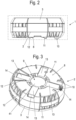
- a device 1 for detecting liquids comprises a tub-shaped housing 2 which has an upper opening which can be closed by a cover 3.
- a circuit board 4 is arranged in the housing 2 and has a capacitive sensor to detect a liquid running under the housing 2 in the event of a leak.
- at least two spaced-apart electrodes are attached to the underside of the circuit board 4, which are monitored by a control on the circuit board 4.
- a battery 5 is attached to the circuit board 4 for the power supply.
- the control on the circuit board 4 can communicate wirelessly with a "monitoring system", for example in a data cloud, which can monitor a large number of devices 1 at the same time.
- a "monitoring system” for example in a data cloud
- corresponding transmitters and receivers are provided on the circuit board 4.
- An acoustic warning device 6 is also provided in the housing 2, which emits acoustic warning signals when a leak is detected.
- the warning device 6 can be encapsulated in order to be able to emit warning signals for as long as possible even if liquid enters the housing 2.
- the circuit board 4 also has an LED for a status display that emits light that is introduced into a rod-shaped light guide 7. The light is guided to a viewing window 30 on the cover 3 via the rod-shaped light guide 7 and is thus visible from the outside.
- the viewing window 30 can be formed by the front side of the light guide 7 so that the LED on the cover 3 is clearly visible.
- an actuating element 31, in particular a push button, is provided on the cover 3, by means of which the control on the circuit board 4 can be operated, for example to start up the device and to start the calibration process.
- Integrally formed locking elements 32 are provided on the cover 3 for fixing the cover 3 to the housing 2.
- the housing 2 with the cover 3 comprises a base 8, which can be placed at a distance from a base via foot elements 10, 11 and 12.
- the foot elements 10, 11 and 12 distributed over the circumference of the housing 2 have a different height, so that the base 8 is inclined to the horizontal on a horizontal, flat base, for example at an angle between 1 ° and 20 °, in particular 2 ° and 10 °.
- the foot elements 10 are designed to be higher than the foot elements 11, and the foot elements 11 are higher than the foot elements 12.
- the foot elements 10, 11 and 12 are web-shaped, but can also have a different geometry.
- An opening 9 is also cut out on the bottom 8 of the housing 2 and is covered by the circuit board 4.
- the circuit board 4 is sealed and glued to the bottom 8 so that no liquid can penetrate into the housing 2 via the opening 9.
- the capacitive sensor 41 with at least two spaced-apart electrodes is provided in the area of the opening 9.
- Flow channels 13 that are open at the bottom are formed on the base 8, through which air can flow out when liquid flows under the base 8.
- four flow channels 13 are provided, starting from the central opening 9, whereby the number of flow channels 13 can be freely selected by the expert.
- the flow channels 13 open into a ventilation channel 14 that ends at a certain height in the housing 2.
- the trough-shaped housing 2 is buoyant with the glued circuit board 4 and can thus float when the liquid level rises.
- the circuit board 4 is shown with the battery 5.
- the circuit board 4 comprises a light source 40 in the form of an LED, which emits light into the rod-shaped light guide 7 and can thus send out a status display via the viewing window 30.
- the capacitive sensor 41 with the electrodes is also provided on the underside of the circuit board 4 and is arranged in the area of the opening 9 of the housing 2.
- the circuit board 4 also has recesses 42 for exact positioning in the housing 2.
- Further electronic components 43 can be provided on the circuit board 4, in particular also operating elements such as push buttons to switch the device on or off or suitable radio components for the wireless transmission of status parameters.
- Evaluation electronics can also be arranged on the circuit board 4, which determines in which state a warning message is issued.
- the housing 2 and optionally also the cover 3 are preferably made of an electrically conductive plastic which is also acid and alkali resistant.
- the device is used, for example, in collecting trays for the transport and storage of liquid hazardous substances.
Landscapes
- Physics & Mathematics (AREA)
- General Physics & Mathematics (AREA)
- Business, Economics & Management (AREA)
- Emergency Management (AREA)
- Examining Or Testing Airtightness (AREA)
- Investigating Or Analyzing Materials By The Use Of Electric Means (AREA)
- Measurement Of Levels Of Liquids Or Fluent Solid Materials (AREA)
Claims (13)
- Dispositif (1) pour la détection de liquide, en particulier en cas de fuite, avec un boîtier (2) sur un fond (8) duquel est disposé un capteur capacitif (41) relié à une unité de commande pour la détection d'un liquide passant sous le fond (8), lequel fond (8) peut être écarté à distance d'un support sur des éléments formant des pieds (10, 11, 12), caractérisé en ce que les éléments formant des pieds (10, 11, 12) ont une hauteur différente, de sorte que le fond (8) est incliné par rapport à l'horizontale quand le support est horizontal et plan.
- Dispositif selon la revendication 1, caractérisé en ce qu'est prévu dans le fond (8) au moins un canal de circulation (13) pour l'air, à travers lequel l'air peut s'échapper quand un liquide circule sous le fond (8).
- Dispositif selon la revendication 1 ou 2, caractérisé en ce que l'inclinaison du fond (8) est comprise entre 1° et 20°, en particulier entre 2° et 10°, par rapport à l'horizontale.
- Dispositif selon l'une des revendications précédentes, caractérisé en ce que le capteur capacitif (41) est disposé sur une carte de circuits (4) qui recouvre au moins par zones une ouverture (9) dans le fond (8) du boîtier (2).
- Dispositif selon la revendication 4, caractérisé en ce que la carte de circuits (4) est collée hermétiquement au fond (8) du boîtier (2).
- Dispositif selon l'une des revendications précédentes, caractérisé en ce qu'est prévu sur la carte de circuits (4) un logement pour une ou plusieurs piles (5) destinées à alimenter en énergie le capteur (41) et l'unité de commande.
- Dispositif selon l'une des revendications précédentes, caractérisé en ce que le boîtier (2) comporte une partie inférieure en forme d'auge qui peut flotter avec la carte de circuits (4).
- Dispositif selon l'une des revendications précédentes, caractérisé en ce que le boîtier (2) comporte une ouverture supérieure qui est fermée par un couvercle (3).
- Dispositif selon la revendication 8, caractérisé en ce qu'un indicateur (30) et/ou un élément de commande (31) sont prévus sur le couvercle.
- Dispositif selon l'une des revendications précédentes, caractérisé en ce qu'une lampe (40) servant d'indicateur d'état est prévue sur la carte de circuits (4) et sa lumière est amenée par un guide d'ondes lumineuses (7) en forme de barre jusqu'à une fenêtre de visualisation (30) sur un couvercle (3).
- Dispositif selon l'une des revendications précédentes, caractérisé en ce que le capteur (41) comporte au moins deux électrodes écartées l'une de l'autre, qui sont placées sur une carte de circuits (4).
- Dispositif selon l'une des revendications précédentes, caractérisé en ce que l'unité de commande comprend un émetteur et un récepteur radio au moyen desquels elle peut communiquer par l'intermédiaire d'une infrastructure d'échange de données telle qu'un nuage de données.
- Dispositif selon l'une des revendications précédentes, caractérisé en ce que le boîtier (2) est fait d'une matière plastique conductrice électrique.
Applications Claiming Priority (2)
| Application Number | Priority Date | Filing Date | Title |
|---|---|---|---|
| DE202019104142.0U DE202019104142U1 (de) | 2019-07-26 | 2019-07-26 | Vorrichtung zur Erfassung von Flüssigkeiten |
| PCT/EP2020/067357 WO2021018476A1 (fr) | 2019-07-26 | 2020-06-22 | Dispositif de détection de liquides |
Publications (4)
| Publication Number | Publication Date |
|---|---|
| EP4004515A1 EP4004515A1 (fr) | 2022-06-01 |
| EP4004515B1 true EP4004515B1 (fr) | 2024-07-31 |
| EP4004515C0 EP4004515C0 (fr) | 2024-07-31 |
| EP4004515B8 EP4004515B8 (fr) | 2024-09-11 |
Family
ID=71994463
Family Applications (1)
| Application Number | Title | Priority Date | Filing Date |
|---|---|---|---|
| EP20753288.8A Active EP4004515B8 (fr) | 2019-07-26 | 2020-06-22 | Dispositif de détection de liquides |
Country Status (3)
| Country | Link |
|---|---|
| EP (1) | EP4004515B8 (fr) |
| DE (1) | DE202019104142U1 (fr) |
| WO (1) | WO2021018476A1 (fr) |
Families Citing this family (1)
| Publication number | Priority date | Publication date | Assignee | Title |
|---|---|---|---|---|
| WO2024134263A1 (fr) | 2022-12-23 | 2024-06-27 | Intechfloor Sa | Bande de capteur pour détection de liquide ou d'humidité et applications et utilisations associées |
Citations (1)
| Publication number | Priority date | Publication date | Assignee | Title |
|---|---|---|---|---|
| US20110048555A1 (en) * | 2009-09-03 | 2011-03-03 | Sam Malouf | Sink alert water leak detector |
Family Cites Families (9)
| Publication number | Priority date | Publication date | Assignee | Title |
|---|---|---|---|---|
| DE4031522C1 (fr) | 1990-10-05 | 1992-04-02 | Horst Dipl.-Ing. 2000 Hamburg De Krauleidies | |
| US5202667A (en) * | 1990-10-19 | 1993-04-13 | Monitoring Systems, Inc. | Electric leakage detector for underground storage tank systems |
| KR20060084160A (ko) * | 2005-01-19 | 2006-07-24 | 레시너코리아 주식회사 | 정전용량형 누수 감지센서 |
| JP2008285005A (ja) * | 2007-05-17 | 2008-11-27 | Nsk Ltd | 電動パワーステアリング装置 |
| DE202008003354U1 (de) * | 2008-03-09 | 2008-05-15 | Hidde, Axel R., Dr. Ing. | Leckageüberwachung bei zylindrischen Anordnungen |
| US9671306B2 (en) * | 2011-05-23 | 2017-06-06 | Widget Lab Inc. | Water leak warning device |
| CA3010340C (fr) * | 2015-12-31 | 2021-06-15 | Delta Faucet Company | Capteur d'eau |
| JP2018159646A (ja) * | 2017-03-23 | 2018-10-11 | 株式会社デンソーウェーブ | 漏水検出器 |
| US11378538B2 (en) * | 2017-09-28 | 2022-07-05 | Nortek Security & Control Llc | Water detector |
-
2019
- 2019-07-26 DE DE202019104142.0U patent/DE202019104142U1/de active Active
-
2020
- 2020-06-22 EP EP20753288.8A patent/EP4004515B8/fr active Active
- 2020-06-22 WO PCT/EP2020/067357 patent/WO2021018476A1/fr not_active Ceased
Patent Citations (1)
| Publication number | Priority date | Publication date | Assignee | Title |
|---|---|---|---|---|
| US20110048555A1 (en) * | 2009-09-03 | 2011-03-03 | Sam Malouf | Sink alert water leak detector |
Also Published As
| Publication number | Publication date |
|---|---|
| EP4004515B8 (fr) | 2024-09-11 |
| WO2021018476A1 (fr) | 2021-02-04 |
| EP4004515A1 (fr) | 2022-06-01 |
| DE202019104142U1 (de) | 2020-10-27 |
| EP4004515C0 (fr) | 2024-07-31 |
Similar Documents
| Publication | Publication Date | Title |
|---|---|---|
| EP1476730A1 (fr) | Procede et dispositif pour la determination optique de niveaux de contenants pour liquides | |
| EP4004515B1 (fr) | Dispositif de détection de liquides | |
| US5192932A (en) | Sensing mat, and methods of constructing and utilizing same | |
| DE202008003354U1 (de) | Leckageüberwachung bei zylindrischen Anordnungen | |
| DE3243839A1 (de) | Vorrichtung zur hoehenstandsmessung von fluessigkeiten in behaeltern, insbesondere fuellstandsanzeige fuer kraftfahrzeuge | |
| EP4004429B1 (fr) | Dispositif de détection de liquides | |
| DE4013746A1 (de) | Fluessigkeitsdetektor | |
| DE20022433U1 (de) | Sensor zum Messen der Eigenschaften eines gasförmigen oder flüssigen Mediums | |
| EP1621863A2 (fr) | Dispositif de détection d'une fuite | |
| DE102017104217B3 (de) | Tränkeeimer | |
| DE102007061187A1 (de) | Vorrichtung zur Positionsbestimmung eines Schwimmerkörpers und Vorrichtung zur Aufnahme einer Flüssigkeit | |
| DE19913530A1 (de) | Niveauabhängige Steuerung von Pumpen | |
| EP2455727B1 (fr) | Séparateur de matière légère | |
| DE69232306T2 (de) | Gerät und verfahren zur detektion von öl auf wasser | |
| US7859273B2 (en) | Sensor for detecting organic liquids | |
| CN218432723U (zh) | 一种智能贮存废油的集油箱 | |
| EP3635358B1 (fr) | Dispositif pour la détection de fuite et la surveillance de l'humidité | |
| US20030019292A1 (en) | Aircraft fuel level gauge | |
| US10107669B2 (en) | Liquid level sensor with insulating region over the probe foot | |
| DE602004011232T2 (de) | Füllstandssensor, der seine Betriebsenergie aus einem Anzeigeinstrument gewinnt | |
| EP3592910B1 (fr) | Capteur et appareil de puisard | |
| CN106768197A (zh) | 一种新型水位监测装置 | |
| DE102010027324B4 (de) | Füllstandsanzeige | |
| AT408695B (de) | Sonde zur gewässerüberwachung | |
| DE102004019351A1 (de) | Geschirrspülmaschine mit einem System zur Füllstandserkennung |
Legal Events
| Date | Code | Title | Description |
|---|---|---|---|
| STAA | Information on the status of an ep patent application or granted ep patent |
Free format text: STATUS: UNKNOWN |
|
| STAA | Information on the status of an ep patent application or granted ep patent |
Free format text: STATUS: THE INTERNATIONAL PUBLICATION HAS BEEN MADE |
|
| PUAI | Public reference made under article 153(3) epc to a published international application that has entered the european phase |
Free format text: ORIGINAL CODE: 0009012 |
|
| STAA | Information on the status of an ep patent application or granted ep patent |
Free format text: STATUS: REQUEST FOR EXAMINATION WAS MADE |
|
| 17P | Request for examination filed |
Effective date: 20211110 |
|
| AK | Designated contracting states |
Kind code of ref document: A1 Designated state(s): AL AT BE BG CH CY CZ DE DK EE ES FI FR GB GR HR HU IE IS IT LI LT LU LV MC MK MT NL NO PL PT RO RS SE SI SK SM TR |
|
| DAV | Request for validation of the european patent (deleted) | ||
| DAX | Request for extension of the european patent (deleted) | ||
| GRAP | Despatch of communication of intention to grant a patent |
Free format text: ORIGINAL CODE: EPIDOSNIGR1 |
|
| STAA | Information on the status of an ep patent application or granted ep patent |
Free format text: STATUS: GRANT OF PATENT IS INTENDED |
|
| INTG | Intention to grant announced |
Effective date: 20240320 |
|
| GRAS | Grant fee paid |
Free format text: ORIGINAL CODE: EPIDOSNIGR3 |
|
| GRAA | (expected) grant |
Free format text: ORIGINAL CODE: 0009210 |
|
| STAA | Information on the status of an ep patent application or granted ep patent |
Free format text: STATUS: THE PATENT HAS BEEN GRANTED |
|
| REG | Reference to a national code |
Ref country code: DE Ref legal event code: R081 Ref document number: 502020008751 Country of ref document: DE Owner name: DENIOS SE, DE Free format text: FORMER OWNER: ANMELDERANGABEN UNKLAR / UNVOLLSTAENDIG, 80297 MUENCHEN, DE |
|
| AK | Designated contracting states |
Kind code of ref document: B1 Designated state(s): AL AT BE BG CH CY CZ DE DK EE ES FI FR GB GR HR HU IE IS IT LI LT LU LV MC MK MT NL NO PL PT RO RS SE SI SK SM TR |
|
| REG | Reference to a national code |
Ref country code: CH Ref legal event code: EP Ref country code: GB Ref legal event code: FG4D Free format text: NOT ENGLISH |
|
| REG | Reference to a national code |
Ref country code: DE Ref legal event code: R096 Ref document number: 502020008751 Country of ref document: DE |
|
| REG | Reference to a national code |
Ref country code: CH Ref legal event code: PK Free format text: BERICHTIGUNG B8 |
|
| RAP4 | Party data changed (patent owner data changed or rights of a patent transferred) |
Owner name: DENIOS SE |
|
| REG | Reference to a national code |
Ref country code: IE Ref legal event code: FG4D Free format text: LANGUAGE OF EP DOCUMENT: GERMAN |
|
| U01 | Request for unitary effect filed |
Effective date: 20240823 |
|
| U07 | Unitary effect registered |
Designated state(s): AT BE BG DE DK EE FI FR IT LT LU LV MT NL PT RO SE SI Effective date: 20240903 |
|
| PG25 | Lapsed in a contracting state [announced via postgrant information from national office to epo] |
Ref country code: NO Free format text: LAPSE BECAUSE OF FAILURE TO SUBMIT A TRANSLATION OF THE DESCRIPTION OR TO PAY THE FEE WITHIN THE PRESCRIBED TIME-LIMIT Effective date: 20241031 |
|
| PG25 | Lapsed in a contracting state [announced via postgrant information from national office to epo] |
Ref country code: PL Free format text: LAPSE BECAUSE OF FAILURE TO SUBMIT A TRANSLATION OF THE DESCRIPTION OR TO PAY THE FEE WITHIN THE PRESCRIBED TIME-LIMIT Effective date: 20240731 Ref country code: GR Free format text: LAPSE BECAUSE OF FAILURE TO SUBMIT A TRANSLATION OF THE DESCRIPTION OR TO PAY THE FEE WITHIN THE PRESCRIBED TIME-LIMIT Effective date: 20241101 |
|
| PG25 | Lapsed in a contracting state [announced via postgrant information from national office to epo] |
Ref country code: IS Free format text: LAPSE BECAUSE OF FAILURE TO SUBMIT A TRANSLATION OF THE DESCRIPTION OR TO PAY THE FEE WITHIN THE PRESCRIBED TIME-LIMIT Effective date: 20241130 |
|
| PG25 | Lapsed in a contracting state [announced via postgrant information from national office to epo] |
Ref country code: HR Free format text: LAPSE BECAUSE OF FAILURE TO SUBMIT A TRANSLATION OF THE DESCRIPTION OR TO PAY THE FEE WITHIN THE PRESCRIBED TIME-LIMIT Effective date: 20240731 |
|
| PG25 | Lapsed in a contracting state [announced via postgrant information from national office to epo] |
Ref country code: ES Free format text: LAPSE BECAUSE OF FAILURE TO SUBMIT A TRANSLATION OF THE DESCRIPTION OR TO PAY THE FEE WITHIN THE PRESCRIBED TIME-LIMIT Effective date: 20240731 Ref country code: RS Free format text: LAPSE BECAUSE OF FAILURE TO SUBMIT A TRANSLATION OF THE DESCRIPTION OR TO PAY THE FEE WITHIN THE PRESCRIBED TIME-LIMIT Effective date: 20241031 |
|
| PG25 | Lapsed in a contracting state [announced via postgrant information from national office to epo] |
Ref country code: RS Free format text: LAPSE BECAUSE OF FAILURE TO SUBMIT A TRANSLATION OF THE DESCRIPTION OR TO PAY THE FEE WITHIN THE PRESCRIBED TIME-LIMIT Effective date: 20241031 Ref country code: PL Free format text: LAPSE BECAUSE OF FAILURE TO SUBMIT A TRANSLATION OF THE DESCRIPTION OR TO PAY THE FEE WITHIN THE PRESCRIBED TIME-LIMIT Effective date: 20240731 Ref country code: NO Free format text: LAPSE BECAUSE OF FAILURE TO SUBMIT A TRANSLATION OF THE DESCRIPTION OR TO PAY THE FEE WITHIN THE PRESCRIBED TIME-LIMIT Effective date: 20241031 Ref country code: IS Free format text: LAPSE BECAUSE OF FAILURE TO SUBMIT A TRANSLATION OF THE DESCRIPTION OR TO PAY THE FEE WITHIN THE PRESCRIBED TIME-LIMIT Effective date: 20241130 Ref country code: HR Free format text: LAPSE BECAUSE OF FAILURE TO SUBMIT A TRANSLATION OF THE DESCRIPTION OR TO PAY THE FEE WITHIN THE PRESCRIBED TIME-LIMIT Effective date: 20240731 Ref country code: GR Free format text: LAPSE BECAUSE OF FAILURE TO SUBMIT A TRANSLATION OF THE DESCRIPTION OR TO PAY THE FEE WITHIN THE PRESCRIBED TIME-LIMIT Effective date: 20241101 Ref country code: ES Free format text: LAPSE BECAUSE OF FAILURE TO SUBMIT A TRANSLATION OF THE DESCRIPTION OR TO PAY THE FEE WITHIN THE PRESCRIBED TIME-LIMIT Effective date: 20240731 |
|
| PG25 | Lapsed in a contracting state [announced via postgrant information from national office to epo] |
Ref country code: SM Free format text: LAPSE BECAUSE OF FAILURE TO SUBMIT A TRANSLATION OF THE DESCRIPTION OR TO PAY THE FEE WITHIN THE PRESCRIBED TIME-LIMIT Effective date: 20240731 |
|
| PG25 | Lapsed in a contracting state [announced via postgrant information from national office to epo] |
Ref country code: CZ Free format text: LAPSE BECAUSE OF FAILURE TO SUBMIT A TRANSLATION OF THE DESCRIPTION OR TO PAY THE FEE WITHIN THE PRESCRIBED TIME-LIMIT Effective date: 20240731 |
|
| PG25 | Lapsed in a contracting state [announced via postgrant information from national office to epo] |
Ref country code: SK Free format text: LAPSE BECAUSE OF FAILURE TO SUBMIT A TRANSLATION OF THE DESCRIPTION OR TO PAY THE FEE WITHIN THE PRESCRIBED TIME-LIMIT Effective date: 20240731 |
|
| U20 | Renewal fee for the european patent with unitary effect paid |
Year of fee payment: 6 Effective date: 20250401 |
|
| PLBE | No opposition filed within time limit |
Free format text: ORIGINAL CODE: 0009261 |
|
| STAA | Information on the status of an ep patent application or granted ep patent |
Free format text: STATUS: NO OPPOSITION FILED WITHIN TIME LIMIT |
|
| 26N | No opposition filed |
Effective date: 20250501 |
|
| REG | Reference to a national code |
Ref country code: CH Ref legal event code: H13 Free format text: ST27 STATUS EVENT CODE: U-0-0-H10-H13 (AS PROVIDED BY THE NATIONAL OFFICE) Effective date: 20260127 |
|
| PG25 | Lapsed in a contracting state [announced via postgrant information from national office to epo] |
Ref country code: MC Free format text: LAPSE BECAUSE OF FAILURE TO SUBMIT A TRANSLATION OF THE DESCRIPTION OR TO PAY THE FEE WITHIN THE PRESCRIBED TIME-LIMIT Effective date: 20240731 |
|
| GBPC | Gb: european patent ceased through non-payment of renewal fee |
Effective date: 20250622 |
|
| PG25 | Lapsed in a contracting state [announced via postgrant information from national office to epo] |
Ref country code: GB Free format text: LAPSE BECAUSE OF NON-PAYMENT OF DUE FEES Effective date: 20250622 |
|
| PG25 | Lapsed in a contracting state [announced via postgrant information from national office to epo] |
Ref country code: IE Free format text: LAPSE BECAUSE OF NON-PAYMENT OF DUE FEES Effective date: 20250622 |
|
| PG25 | Lapsed in a contracting state [announced via postgrant information from national office to epo] |
Ref country code: CH Free format text: LAPSE BECAUSE OF NON-PAYMENT OF DUE FEES Effective date: 20250630 |