EP4004521B1 - Differenzielles dosierverfahren - Google Patents
Differenzielles dosierverfahren Download PDFInfo
- Publication number
- EP4004521B1 EP4004521B1 EP19780341.4A EP19780341A EP4004521B1 EP 4004521 B1 EP4004521 B1 EP 4004521B1 EP 19780341 A EP19780341 A EP 19780341A EP 4004521 B1 EP4004521 B1 EP 4004521B1
- Authority
- EP
- European Patent Office
- Prior art keywords
- dilution
- liquid
- chamber
- calibrated
- pathway
- Prior art date
- Legal status (The legal status is an assumption and is not a legal conclusion. Google has not performed a legal analysis and makes no representation as to the accuracy of the status listed.)
- Active
Links
Images

Classifications
-
- G—PHYSICS
- G01—MEASURING; TESTING
- G01N—INVESTIGATING OR ANALYSING MATERIALS BY DETERMINING THEIR CHEMICAL OR PHYSICAL PROPERTIES
- G01N1/00—Sampling; Preparing specimens for investigation
- G01N1/28—Preparing specimens for investigation including physical details of (bio-)chemical methods covered elsewhere, e.g. G01N33/50, C12Q
- G01N1/38—Diluting, dispersing or mixing samples
-
- G—PHYSICS
- G01—MEASURING; TESTING
- G01N—INVESTIGATING OR ANALYSING MATERIALS BY DETERMINING THEIR CHEMICAL OR PHYSICAL PROPERTIES
- G01N15/00—Investigating characteristics of particles; Investigating permeability, pore-volume or surface-area of porous materials
- G01N15/10—Investigating individual particles
- G01N15/14—Optical investigation techniques, e.g. flow cytometry
- G01N15/1434—Optical arrangements
- G01N15/1436—Optical arrangements the optical arrangement forming an integrated apparatus with the sample container, e.g. a flow cell
-
- G—PHYSICS
- G01—MEASURING; TESTING
- G01N—INVESTIGATING OR ANALYSING MATERIALS BY DETERMINING THEIR CHEMICAL OR PHYSICAL PROPERTIES
- G01N35/00—Automatic analysis not limited to methods or materials provided for in any single one of groups G01N1/00 - G01N33/00; Handling materials therefor
- G01N35/10—Devices for transferring samples or any liquids to, in, or from, the analysis apparatus, e.g. suction devices, injection devices
- G01N35/1095—Devices for transferring samples or any liquids to, in, or from, the analysis apparatus, e.g. suction devices, injection devices for supplying the samples to flow-through analysers
- G01N35/1097—Devices for transferring samples or any liquids to, in, or from, the analysis apparatus, e.g. suction devices, injection devices for supplying the samples to flow-through analysers characterised by the valves
-
- G—PHYSICS
- G01—MEASURING; TESTING
- G01N—INVESTIGATING OR ANALYSING MATERIALS BY DETERMINING THEIR CHEMICAL OR PHYSICAL PROPERTIES
- G01N15/00—Investigating characteristics of particles; Investigating permeability, pore-volume or surface-area of porous materials
- G01N15/01—Investigating characteristics of particles; Investigating permeability, pore-volume or surface-area of porous materials specially adapted for biological cells, e.g. blood cells
- G01N2015/011—Investigating characteristics of particles; Investigating permeability, pore-volume or surface-area of porous materials specially adapted for biological cells, e.g. blood cells with lysing, e.g. of erythrocytes
-
- G—PHYSICS
- G01—MEASURING; TESTING
- G01N—INVESTIGATING OR ANALYSING MATERIALS BY DETERMINING THEIR CHEMICAL OR PHYSICAL PROPERTIES
- G01N35/00—Automatic analysis not limited to methods or materials provided for in any single one of groups G01N1/00 - G01N33/00; Handling materials therefor
- G01N35/10—Devices for transferring samples or any liquids to, in, or from, the analysis apparatus, e.g. suction devices, injection devices
- G01N2035/1027—General features of the devices
- G01N2035/1032—Dilution or aliquotting
Definitions
- the present invention relates to a method for dilution of a sample for analysis and to a haematology apparatus for implementation of such a method.
- This sample may be blood or other biological liquid such as, for example a puncture fluid such as a cerebrospinal fluid (CSF) containing white blood cells or red blood cells.
- CSF cerebrospinal fluid
- a haematology apparatus makes it possible to count and characterize different types of cells present in the blood.
- JPH04369461A discloses a quantitative sampling system for quantitatively sampling whole blood and diluting it with a constant dilution ratio.
- the document US4726237A discloses a transfer valve system having a three element valve with a central element sandwiched between front and rear outer elements. Between an aspiration and a discharge position the front and rear outer elements are moved in opposite directions of unequal distances in the same direction with respect to the central member or one outer member and the central member are moved in the same or opposite direction with respect to the other outer member so long as the outer members end up shifted with respect to each other. In the aspiration position, two sample segments are contained in series within the valve.
- US3567390A discloses a diluting system equipped with a transfer valve for providing a plurality of dilutions of differing concentration from a single fluid sample.
- the document US3712144A discloses an automatic diluter and photometric reader adapted for use in the turbidimetric microbiological assays of antibiotics.
- the automatic diluter comprises a valve and a pair of loops of a predetermined volume.
- the document CN109959549A discloses a sample testing method wherein biological sample is once diluted in the first reaction tank, to form a diluted sample; sample lines are driven to extract a diluted sample by driving device; the part diluted sample in the sample lines is pushed into the second reaction tank by the driving device; secondary dilution is carried out to the diluted sample in second reaction tank, to form secondary dilution sample; and detection of the secondary dilution sample.
- JPS4833149B1 discloses a method for diluting a liquid containing particles with two types of diluents having different dilution ratios.
- the document US 6,333,197 (ABX) is also known, describing a needle for collecting blood and injecting it into different chambers at the same time as a reagent to produce a homogenous dilution.
- the system described in this document US 6,333,197 requires collection of a large quantity of whole blood which by design is not totally used.
- the positioning of the needle in the different chambers is complex due to the requirement for the alignment of the needle with the arrival of the reagent.
- the chambers are specifically designed in order to allow the homogenization of the blood with the reagent.
- An object of the present invention is a novel dispensing method that is rapid and simple to implement.
- Another object of the invention is a novel method using a small quantity of whole blood for characterizing the blood cells, for example the white blood cells and the reticulocytes.
- At least one of the above-mentioned objectives is achieved with a method according to claim 1.
- This single collection can, for example, be a quantity of 20 ⁇ l of whole or diluted blood, whereas in the prior art this collection is generally of the order of 120 ⁇ l or more.
- This method has the advantage of being simple to implement because the retention of the first-dilution liquid in the aliquoting device for the second and the third dilutions is cleverly used.
- the method according to the invention allows high analysis speeds.
- the second- and third-dilution liquids are obtained independently of one another, i.e. the third-dilution liquid is not obtained from the second-dilution liquid but directly from the first-dilution liquid retained in the aliquoting device.
- the dilutions can take place successively in several chambers.
- the analysis can comprise characterizing the first and/or second and/or third dilution liquid by optical measurement for counting and/or differentiating particles contained in the liquid.
- the analysis can comprise counting particles in the first- and/or second- and/or third-dilution liquids, by means of a resistive sensor.
- the optical measurement can take place on an optical bench or in the chamber used for the dilution, this chamber then being equipped with an optical device.
- one or more resistive sensors can be connected to or incorporated in at least one chamber or in an optical bench.
- optical bench is meant a device making it possible to:
- step e) can further comprise the following steps before step e7):
- the analysis speed is very high.
- step e10) it is possible to transfer to the optical bench a portion of the third-dilution liquid for differentiation of the red blood cells, in particular the immature red blood cells, the reticulocytes.
- a single sample collection allows differentiation of the white blood cells and differentiation of the red blood cells.
- an aliquoting device comprising:
- a sampling valve can be designed comprising two ceramic discs, one of which contains the calibrated-volume channel. This channel can be shifted between two positions, a first position where the channel is comprised within the first liquid pathway and a second position where the channel is comprised within the second liquid pathway.
- the invention is in particular remarkable for the re-use of the first dilution present in the needle up to the sampling valve.
- Step d) can preferably be carried out by collecting the sample and retaining it inside the needle and in the calibrated-volume channel of the sampling valve.
- Step d) can preferably be carried out by collecting the sample and retaining it inside the needle and in the calibrated-volume channel of the sampling valve.
- the sampling valve forms part of the fluidics circuit for collecting the first dilution.
- the needle makes it possible to collect the first dilution in the first chamber, but injection into the second chamber is carried out directly via the second liquid pathway. More precisely, a tube makes it possible to link the sampling valve to the second chamber. This feature makes it possible, for example, to carry out the second dilution while retaining a portion of the first dilution in the needle, which makes it possible to subsequently dispense a portion of it into the first chamber for the third dilution without being obliged to carry out a new collection of the sample.
- step d) can be carried out by collecting the first-dilution liquid and retaining it inside the needle and in the sampling valve.
- the first-dilution liquid is preferably aspirated into the sampling valve and beyond this valve into a tube between the sampling valve and the dispenser.
- an aliquoting device comprising one or more sets of precision pistons/syringes in order to collect and inject the sample and the different dilutions from and into the different chambers.
- the volumes injected in order to carry out the first dilution and the third dilution are determined by precisely controlling the piston(s)/syringe(s).
- the steps of the first and second dilutions can preferably be carried out by injecting a reagent of dilution via the aliquoting device.
- the aliquoting device comprises a needle and the sampling valve
- the two liquid pathways comprise tubes in which the dilution reagent originating from the dilution reagent dispenser serves as liquid for dispensing the sample and/or dilution reagent.
- all or some of the dilution steps can be carried out by injecting dilution reagent from a liquid pathway independent of the aliquoting device and directly into the chamber or chambers.
- a single optical bench linked to the first chamber can be used.
- all or some of the counts are carried out by means of resistive sensors connected to the first and/or second chamber and/or to other chambers if there are more than two chambers.
- the first dilution can have a ratio of 1/200
- the second dilution can have a ratio of 1/10,000
- the third dilution can have a ratio of 1/10,000.
- the injection of the lysis solution in step e3) can be carried out via a liquid pathway independent of the aliquoting device and directly into the first chamber.
- This lysis solution has the function of destroying the red blood cells and separating the white blood cells. This also allows stabilization of the haemoglobin in the form of a stable complex.
- the method can comprise a step of adding a fluorescent dye to the first chamber before each optical differentiation measurement.
- An optical bench making it possible to detect the fluorescence can preferably be used. It is thus possible to detect the reticulocytes, immature red blood cells, thanks to the presence of the fluorescent dye.
- a fluorescent dye to the first- and/or second- and/or third-dilution liquid before any optical measurement, so as to improve the differentiation of the blood cells for example the white blood cells or/and the characterization of the reticulocytes using fluorescence.
- steps e5) and e6) can be carried out in parallel or sequentially.
- the counts in parallel are carried out using a single aspiration system, allowing aspiration from both chambers into different channels at the same time. It is perfectly possible to envisage separate (non-simultaneous) counts with a single or several distinct aspiration systems.
- a haematology apparatus for the automatic counting and differentiation of cells in a blood sample characterized in that it comprises:
- a treatment unit for implementing the different steps and controlling the different components is also provided.
- the sampling valve according to the invention can contain a calibrated-volume channel, this calibrated-volume channel being capable of constituting either a part of the first liquid pathway or a part of the second.
- the calibrated-volume channel switches over from one liquid pathway to the other.
- the dispenser can control the aspiration or the expulsion of a portion of the liquid contained in the first liquid pathway, the second liquid pathway being non-operational.
- the dispenser can control the expulsion of a portion of the liquid contained in the second liquid pathway, the first liquid pathway then being non-operational.
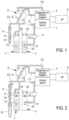
- Figure 1 illustrates components constituting an automatic haematology analyser that is ready for use, awaiting an analysis cycle.
- An optical bench 1 for characterizing different types of cells present in the blood can be seen.
- a first chamber 2 is linked to the optical bench 1 via a solenoid valve 3 capable of blocking or allowing the passage of fluid contained in the first chamber 2 to the optical bench 1.
- the first chamber 2 comprises an outlet 21 connecting to the solenoid 3, and electronic means, in particular at least one sensor 22, for resistivity measurements. These measurements are, for example, implemented during cell counts.
- optical bench 1 For the sake of clarity of the diagram, only the optical bench 1 is shown; it is clear that a flow cell (not shown) is provided within this optical bench, in which the fluid to be characterized can flow.
- a dilution reagent dispenser 4 can also be seen, linked to a sampling valve 5 via two parallel conduits C1 and C2.
- the sampling valve 5 is linked on one side to a needle 6 via a conduit C3 and on the other side to a second chamber 7 via a conduit C4.
- the sampling valve 5 is a valve comprising two liquid pathways and a calibrated-volume channel 8.
- the first liquid pathway makes it possible to link the conduits C1 and C3 via the calibrated-volume channel 8.
- the second liquid pathway makes it possible to link the conduits C2 and C4 via the calibrated-volume channel 8.
- This calibrated-volume channel can thus form part of the first liquid pathway or of the second liquid pathway but not both at the same time.
- this calibrated-volume channel 8 is a conduit suitable for switching from one liquid pathway to the other and forms a reservoir of fluid, the volume of which is very precisely predetermined. A predetermined quantity of liquid can thus be sent from one liquid pathway to the other.
- the conduit C4 is connected to the second chamber 7 via an inlet 71.
- a treatment unit 9 capable of controlling the different components can also be seen.
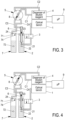
- blood is collected in the needle 6 from a tube of whole blood 10.
- a certain volume of blood is then situated only in a part of the needle.
- the first liquid pathway comprising the conduits C1 and C3 is mainly filled with dilution reagent, except for the part of the needle 6 containing blood. It is via an aspiration function via the dilution reagent dispenser that the needle collects the blood.
- the first chamber 2 is emptied.
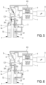
- step 1 in Figure 3 , the needle 6 is moved as far as into the first chamber 2 so as to inject all of the collected blood into it. And the injection is continued so as to fill up with the dilution reagent contained in the first liquid pathway and delivered via the dispenser.
- the mixture of the blood thus deposited with a volume of dilution reagent much greater than the volume of collected blood constitutes the first-dilution liquid with a ratio, for example, of one volume of blood to two hundred volumes of dilution reagent.
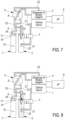
- step 2 in Figure 4 , a portion of the first dilution is collected from the first chamber 2 as far as into a part of the conduit C1. Consequently, the needle 6, the conduit C3 and the sampling valve, in particular the calibrated-volume channel 8, are completely filled with the first-dilution liquid.
- step 3 in Figure 5 , the calibrated-volume channel 8 filled with first-dilution liquid is switched from the first liquid pathway to the second liquid pathway; the latter is now operational.
- the fact of having aspirated in the step 2 the first-dilution liquid as far as into a part of the conduit C1 made it possible to completely fill the calibrated-volume channel 8.
- a second-dilution liquid is thus formed with a ratio, for example, of one volume of clean blood to ten thousand volumes of dilution reagent.
- the needle 6 is raised again so that it does not remain in contact with the liquid in the first chamber 2 and the lysis solution is injected into this first chamber 2 via an inlet 23.
- the lysis solution has the function of destroying the red blood cells.
- the first-dilution liquid remains present in the needle 6 and in a part of the first liquid pathway comprising the conduit C1 and the conduit C3.
- step 4 in Figure 6 the solution is transferred from the first chamber 2 to the optical bench for differentiation of the populations of the white blood cells.
- the white blood cells are counted in the first chamber 2 by measuring resistivity and a haemoglobin measurement is carried out by means of a spectrophotometer (not shown).
- the red blood cells and platelets are counted by measuring resistivity.
- the counting in the second chamber 7 can be carried out simultaneously with the counting in the first chamber. This is particularly the case when a single aspiration system (not shown) is used for both chambers during the counting process.
- the counting sequence requires to aspirate, by means of the generation of a vacuum, the liquid contained in the chamber through a calibrated orifice based on the impedance measurement principle.
- step 5 in Figure 7 the two chambers are rinsed and emptied completely, as is the fluid circuit between the first chamber 2 and the optical bench 1. It is possible to use the dilution reagent for rinsing the chamber, in order to send it in the fluid circuit to the optical bench and thus to rinse and refill this circuit.
- the calibrated-volume channel 8, filled with dilution reagent, is then switched to the first liquid pathway.
- a third dilution is carried out according to the invention.
- a quantity of first-dilution liquid still present in the needle 6 is injected into the first chamber 2.
- a specific volume is pushed.
- a residual first-dilution volume can still be present in the needle 6.
- the dilution is carried out by injecting dilution reagent via an inlet 24 of the first chamber 2.
- the supply circuit of this inlet 24 from the dispenser 4 is not shown.
- a fluorescent dye can also be added.
- step 8 in Figure 9 the solution is transferred from the first chamber 2 to the optical bench 1; then the differentiation of the red blood cells and the reticulocytes is carried out.
- step 9 in Figure 10 when the differentiation is completed, the needle 6 is emptied of residual blood.
- the chambers are rinsed then refilled with dilution reagent, awaiting a subsequent analysis.
- the invention thus makes it possible to perform several differentiation measurements based on a single collection, cleverly using an aliquoting device that allows a first-dilution liquid and the dilution reagent to be segmented.
- the present invention thus relates to a method for dilution of a blood sample for analysis and to an apparatus for implementation of such a method.
- an aliquoting device is used, making it possible to carry out a single collection, to form a first dilution in a chamber, to collect a portion of the first dilution in order to form a second dilution in another chamber, to count the blood cells in the first and the second chamber, to carry out a differentiation based on the first dilution, to rinse the first chamber, to form a third dilution starting from a quantity of first-dilution liquid remaining in the aliquoting device, then to carry out a differentiation of reticulocytes based on this third dilution.
Landscapes
- Chemical & Material Sciences (AREA)
- General Health & Medical Sciences (AREA)
- Life Sciences & Earth Sciences (AREA)
- Health & Medical Sciences (AREA)
- Analytical Chemistry (AREA)
- Biochemistry (AREA)
- Physics & Mathematics (AREA)
- General Physics & Mathematics (AREA)
- Immunology (AREA)
- Pathology (AREA)
- Dispersion Chemistry (AREA)
- Investigating Or Analysing Biological Materials (AREA)
- Sampling And Sample Adjustment (AREA)
Claims (13)
- Verfahren für Verdünnung einer Blutprobe für Analyse, dieses Verfahren umfassend die folgenden Schritte:a) eine einzelne Entnahme der Probe mittels einer Aliquotierungsvorrichtung,b) Injizieren der Probe in eine erste Kammer (2),c) Verdünnen der Probe in dieser Kammer (2) mittels eines Verdünnungsreagenzes, um eine Erstverdünnungsflüssigkeit zu bilden,d) Entnehmen eines Anteils der Erstverdünnungsflüssigkeit mittels der Aliquotierungsvorrichtung,e) Durchführen mindestens zweier weiterer Verdünnungen, um eine Zweitverdünnungsflüssigkeit und eine Drittverdünnungsflüssigkeit zu erhalten, wobei jede der Zweit- und der Drittverdünnungsflüssigkeit von der Erstverdünnungsflüssigkeit, die in der Aliquotierungsvorrichtung enthalten ist, direkt erhalten wird, undf) während der Schritte a) bis e) mindestens eine Analyse der Erstverdünnungsflüssigkeit und/oder der Zweitverdünnungsflüssigkeit und/oder der Drittverdünnungsflüssigkeit,wobei die Aliquotierungsvorrichtung umfasst:- eine Nadel (6), die zwischen einer Probenentnahmezone und der mindestens einen Kammer (2) bewegt werden kann,- einen Verdünnungsreagenzdosierer (4) unddadurch gekennzeichnet, dass die Aliquotierungsvorrichtung ferner umfasst:- ein Probenentnahmeventil (5), umfassend mindestens zwei Flüssigkeitswege und einen kalibrierten Volumenkanal (8), wobei ein erster Flüssigkeitsweg (C2, 8, C3) den Dosierer (4) mit der Nadel (6) verknüpft, ein zweiter Flüssigkeitsweg (C1, 8, C4) den Dosierer (4) mit einer zweiten Kammer (7) verknüpft und der kalibrierte Volumenkanal (8) den ersten Flüssigkeitsweg (C2, 8, C3) oder den zweiten Flüssigkeitsweg (C1, 8, C4) aktiviert, undwobei der Schritt d) durch Entnehmen der Erstverdünnungsflüssigkeit und Zurückhalten derselben in der Nadel (6) und in dem kalibrierten Volumenkanal (8) des Probenentnahmeventils (5) durchgeführt wird,- und dass in Schritt e), um eine erste Menge der Erstverdünnungsflüssigkeit in die zweite Kammer (7) zu injizieren, um die zweite Verdünnung durchzuführen, der kalibrierte Volumenkanal (8), der die erste Menge der Erstverdünnungsflüssigkeit enthält, von dem ersten Flüssigkeitsweg (C2, 8, C3) auf den zweiten Flüssigkeitsweg (C1, 8, C4) umgeschaltet wird, gefolgt von dem Injizieren in die zweite Kammer (7) über den zweiten Flüssigkeitsweg (C1, 8, C4), wobei die erste Menge in dem kalibrierten Volumenkanal (8) des Probenentnahmeventils (5) präzise kalibriert ist; wobei eine zweite Menge der Erstverdünnungsflüssigkeit in der Aliquotierungsvorrichtung verbleibt,und dass Schritt e) ferner die folgenden Schritte umfasst:e7) Spülen der ersten Kammer (2),e8) Injizieren in die erste Kammer (2) eines Anteils der zweiten Menge, der Erstverdünnungsflüssigkeit, die noch in der Aliquotierungsvorrichtung enthalten ist,e9) Verdünnen der Flüssigkeit, die in der ersten Kammer (2) enthalten ist,mittels eines Verdünnungsreagenzes, um eine Drittverdünnungsflüssigkeit zu bilden, wobei die Drittverdünnungsflüssigkeit von der Erstverdünnungsflüssigkeit,die in der Nadel (6) enthalten ist, direkt erhalten wird.
- Verfahren nach Anspruch 1, dadurch gekennzeichnet, dass die Analyse ein Charakterisieren der ersten und/oder der zweiten und/oder der dritten Verdünnungsflüssigkeit durch optische Messung zum Zählen und/oder Differenzieren von Partikeln, die in der Flüssigkeit enthalten sind, umfasst.
- Verfahren nach Anspruch 1 oder 2, dadurch gekennzeichnet, dass die Analyse das Zählen von Partikeln der Erst- und/oder der Zweit- und/oder der Drittverdünnungsflüssigkeit mittels eines Widerstandssensors umfasst.
- Verfahren nach einem der vorstehenden Ansprüche,
dadurch gekennzeichnet, dass die Analyse das Charakterisieren der Drittverdünnungsflüssigkeit durch optische Messung zum Zählen und/oder Differenzieren von Partikeln, die in der Flüssigkeit enthalten sind, umfasst. - Verfahren nach einem der vorstehenden Ansprüche,
dadurch gekennzeichnet, dass Schritt e) ferner die folgenden Schritte umfasst:e2) Verdünnen der Erstverdünnungsflüssigkeit, die in der zweiten Kammer enthalten ist, mittels eines Verdünnungsreagenzes, um eine Zweitverdünnungsflüssigkeit zu bilden,e3) Injizieren einer Lyse-Lösung in die erste Kammer, um rote Blutkörperchen zu zerstören,e4) Differenzieren von weißen Blutkörperchen in der Erstverdünnungsflüssigkeit, die in der ersten Kammer enthalten ist, durch optische Messung direkt in der ersten Kammer oder an einer optischen Bank nach Überführung eines Anteils der Erstverdünnungsflüssigkeit zu dieser optischen Bank,e5) Zählen der roten Blutkörperchen und/oder Blutplättchen in der Zweitverdünnungsflüssigkeit,e6) Zählen der weißen Blutkörperchen und/oder Messen des Hämoglobins in der Erstverdünnungsflüssigkeit,
und nach den Schritten e7)-e9), wie in Anspruch 1 definiert,e10) Analysieren der Drittverdünnungsflüssigkeit. - Verfahren nach Anspruch 5, dadurch gekennzeichnet, dass in Schritt e10) ein Anteil der Drittverdünnungsflüssigkeit für Differenzierung der Retikulozyten zu der optischen Bank überführt wird.
- Verfahren nach einem der vorstehenden Ansprüche,
dadurch gekennzeichnet, dass die Schritte der ersten und der zweiten Verdünnung durch Injizieren von Verdünnungsreagenz über die Aliquotierungsvorrichtung durchgeführt werden. - Verfahren nach einem der Ansprüche 1 bis 6,
dadurch gekennzeichnet, dass alle oder einige der Verdünnungsschritte durch Injizieren von Verdünnungsreagenz von einem Flüssigkeitsweg (24, 74), der von der Aliquotierungsvorrichtung unabhängig ist, direkt in die Kammer oder die Kammern durchgeführt werden. - Verfahren nach einem der vorstehenden Ansprüche,
dadurch gekennzeichnet, dass eine einzelne optische Bank, die mit der ersten Kammer verknüpft ist, verwendet wird. - Verfahren nach einem der vorstehenden Ansprüche,
dadurch gekennzeichnet, dass die erste Verdünnung ein Verhältnis von 1/200 aufweist, die zweite Verdünnung ein Verhältnis von 1/10.000 aufweist und die dritte Verdünnung ein Verhältnis von 1/10.000 aufweist. - Verfahren nach einem der vorstehenden Ansprüche,
dadurch gekennzeichnet, dass eine Analyse unter Verwendung einer optischen Bank mit Epifluoreszenz durchgeführt wird. - Hämatologieeinrichtung für die automatische Zählung und Differenzierung von Zellen in einer Blutprobe, umfassend:- mindestens eine Kammer (1),- mindestens eine optische Bank (1), die mit mindestens einer Kammer verknüpft ist,- eine Aliquotierungsvorrichtung, umfassend:- eine Nadel (6), die zwischen einer Probenentnahmezone und mindestens einer Kammer (2, 7) bewegt werden kann,- einen Verdünnungsreagenzdosierer,dadurch gekennzeichnet, dass die Einrichtung ferner umfasst:- ein Probenentnahmeventil, umfassend mindestens zwei Flüssigkeitswege und einen kalibrierten Volumenkanal (8), wobei ein erster Flüssigkeitsweg (C1, 8, C3) den Verdünnungsreagenzdosierer mit der Nadel verknüpft, ein zweiter Flüssigkeitsweg (C2, 8, C4) den Verdünnungsreagenzdosierer mit mindestens einer Kammer verknüpft und der kalibrierte Volumenkanal (8) den ersten Flüssigkeitsweg oder den zweiten Flüssigkeitsweg aktiviert,und eine Behandlungseinheit (9), die konfiguriert ist, um verschiedene Komponenten der Einrichtung zu steuern, und ferner konfiguriert ist, um die verschiedenen Schritte des Verfahrens, wie in Anspruch 1 definiert, zu implementieren.
- Einrichtung nach Anspruch 12, dadurch gekennzeichnet, dass der kalibrierte Volumenkanal (8) ein kalibriertes Volumenrohr enthält, und dass dieser kalibrierte Volumenkanal entweder einen Teil des ersten Flüssigkeitswegs oder einen Teil des zweiten Flüssigkeitswegs bilden kann.
Applications Claiming Priority (1)
| Application Number | Priority Date | Filing Date | Title |
|---|---|---|---|
| PCT/IB2019/000795 WO2021019267A1 (en) | 2019-07-26 | 2019-07-26 | Differential dispensing method |
Publications (2)
| Publication Number | Publication Date |
|---|---|
| EP4004521A1 EP4004521A1 (de) | 2022-06-01 |
| EP4004521B1 true EP4004521B1 (de) | 2025-05-21 |
Family
ID=68109380
Family Applications (1)
| Application Number | Title | Priority Date | Filing Date |
|---|---|---|---|
| EP19780341.4A Active EP4004521B1 (de) | 2019-07-26 | 2019-07-26 | Differenzielles dosierverfahren |
Country Status (8)
| Country | Link |
|---|---|
| US (1) | US12385816B2 (de) |
| EP (1) | EP4004521B1 (de) |
| JP (1) | JP7400073B2 (de) |
| CN (1) | CN114174796B (de) |
| CA (1) | CA3145364A1 (de) |
| ES (1) | ES3036157T3 (de) |
| PL (1) | PL4004521T3 (de) |
| WO (1) | WO2021019267A1 (de) |
Families Citing this family (1)
| Publication number | Priority date | Publication date | Assignee | Title |
|---|---|---|---|---|
| CN118613708A (zh) * | 2021-12-22 | 2024-09-06 | 贝克曼库尔特有限公司 | 生物分析系统中的流体传输 |
Citations (7)
| Publication number | Priority date | Publication date | Assignee | Title |
|---|---|---|---|---|
| US3567390A (en) * | 1968-04-03 | 1971-03-02 | Coulter Electronics | Fluid transfer valve structure and diluting system |
| US3712144A (en) * | 1971-03-10 | 1973-01-23 | Lilly Co Eli | Automated system for performing sample measurement, dilutions and photometric measurements |
| JPS4833149B1 (de) * | 1969-04-19 | 1973-10-12 | ||
| US4726237A (en) * | 1985-06-19 | 1988-02-23 | Sequoia-Turner Corporation | Fluid metering apparatus and method |
| JPH04369461A (ja) * | 1991-06-17 | 1992-12-22 | Hitachi Ltd | 粒子計測装置 |
| US6333197B1 (en) * | 1997-10-28 | 2001-12-25 | A B X | Method and device for fractionated distribution of a blood sample |
| CN109959549A (zh) * | 2017-12-25 | 2019-07-02 | 深圳迈瑞生物医疗电子股份有限公司 | 样本检测方法及样本分析仪 |
Family Cites Families (8)
| Publication number | Priority date | Publication date | Assignee | Title |
|---|---|---|---|---|
| JPH0191255U (de) * | 1987-12-10 | 1989-06-15 | ||
| JP3880181B2 (ja) * | 1997-12-22 | 2007-02-14 | シスメックス株式会社 | 血液分析装置 |
| JP4751544B2 (ja) | 2001-09-07 | 2011-08-17 | シスメックス株式会社 | 自動血液分析装置とその装置に用いるピペット駆動装置 |
| US7661326B2 (en) | 2006-10-26 | 2010-02-16 | Beckman Coulter, Inc. | Apparatus for aspirating and dispensing liquids in an automated analyzer |
| CN108025904B (zh) * | 2015-06-12 | 2021-10-15 | 芯易诊有限公司 | 用于多分析物分析的流体单元和流体卡式盒 |
| CN105973811A (zh) * | 2016-04-28 | 2016-09-28 | 江苏英诺华医疗技术有限公司 | 具有血液分析和生化分析功能的分析仪及方法 |
| CN106885915A (zh) * | 2017-03-16 | 2017-06-23 | 江苏柯伦迪医疗技术有限公司 | 一种新型血液分析仪及方法 |
| CN208026537U (zh) * | 2018-03-02 | 2018-10-30 | 南京科创检测技术有限公司 | 一种定容型自动稀释仪 |
-
2019
- 2019-07-26 CN CN201980098746.1A patent/CN114174796B/zh active Active
- 2019-07-26 EP EP19780341.4A patent/EP4004521B1/de active Active
- 2019-07-26 US US17/597,505 patent/US12385816B2/en active Active
- 2019-07-26 PL PL19780341.4T patent/PL4004521T3/pl unknown
- 2019-07-26 CA CA3145364A patent/CA3145364A1/en active Pending
- 2019-07-26 ES ES19780341T patent/ES3036157T3/es active Active
- 2019-07-26 JP JP2022505393A patent/JP7400073B2/ja active Active
- 2019-07-26 WO PCT/IB2019/000795 patent/WO2021019267A1/en not_active Ceased
Patent Citations (7)
| Publication number | Priority date | Publication date | Assignee | Title |
|---|---|---|---|---|
| US3567390A (en) * | 1968-04-03 | 1971-03-02 | Coulter Electronics | Fluid transfer valve structure and diluting system |
| JPS4833149B1 (de) * | 1969-04-19 | 1973-10-12 | ||
| US3712144A (en) * | 1971-03-10 | 1973-01-23 | Lilly Co Eli | Automated system for performing sample measurement, dilutions and photometric measurements |
| US4726237A (en) * | 1985-06-19 | 1988-02-23 | Sequoia-Turner Corporation | Fluid metering apparatus and method |
| JPH04369461A (ja) * | 1991-06-17 | 1992-12-22 | Hitachi Ltd | 粒子計測装置 |
| US6333197B1 (en) * | 1997-10-28 | 2001-12-25 | A B X | Method and device for fractionated distribution of a blood sample |
| CN109959549A (zh) * | 2017-12-25 | 2019-07-02 | 深圳迈瑞生物医疗电子股份有限公司 | 样本检测方法及样本分析仪 |
Also Published As
| Publication number | Publication date |
|---|---|
| WO2021019267A1 (en) | 2021-02-04 |
| US12385816B2 (en) | 2025-08-12 |
| US20220364963A1 (en) | 2022-11-17 |
| JP2022549557A (ja) | 2022-11-28 |
| EP4004521A1 (de) | 2022-06-01 |
| JP7400073B2 (ja) | 2023-12-18 |
| CN114174796A (zh) | 2022-03-11 |
| PL4004521T3 (pl) | 2025-08-18 |
| CN114174796B (zh) | 2025-06-24 |
| CA3145364A1 (en) | 2021-02-04 |
| ES3036157T3 (en) | 2025-09-15 |
Similar Documents
| Publication | Publication Date | Title |
|---|---|---|
| US12117601B2 (en) | Automated microscopic cell analysis | |
| US5380491A (en) | Apparatus for pumping and directing fluids for hematology testing | |
| CN101529243B (zh) | 用于在自动分析仪中吸出和分配液体的装置 | |
| EP3207358B1 (de) | Systeme und verfahren zur abbildung flüssiger proben | |
| WO1994016305A2 (en) | Liquid metering and transfer valve assembly particularly for flow cytometer | |
| US20050169802A1 (en) | Apparatus for pumping and directing fluids for hematology testing | |
| EP4004521B1 (de) | Differenzielles dosierverfahren | |
| CN212379420U (zh) | 样本分析仪 | |
| CN114002446B (zh) | 样本分析仪及其检测方法 | |
| CN101283261B (zh) | 用于分析血液等生物流体的模块化装置 | |
| KR101762868B1 (ko) | 자동 혈구 분석용 멀티 디스펜서 | |
| KR20170091898A (ko) | 자동 혈구 분석용 멀티 디스펜서 | |
| EP0789843B1 (de) | Vorrichtung zum pumpen und führen von flüssigkeiten im zusammenhang mit hämatologischen prüfungen | |
| JPH04369461A (ja) | 粒子計測装置 | |
| JP2025500966A (ja) | 生物学的分析システムにおける流体輸送 | |
| CA2199256A1 (en) | Apparatus for pumping and directing fluids for hematology testing |
Legal Events
| Date | Code | Title | Description |
|---|---|---|---|
| STAA | Information on the status of an ep patent application or granted ep patent |
Free format text: STATUS: UNKNOWN |
|
| STAA | Information on the status of an ep patent application or granted ep patent |
Free format text: STATUS: THE INTERNATIONAL PUBLICATION HAS BEEN MADE |
|
| PUAI | Public reference made under article 153(3) epc to a published international application that has entered the european phase |
Free format text: ORIGINAL CODE: 0009012 |
|
| STAA | Information on the status of an ep patent application or granted ep patent |
Free format text: STATUS: REQUEST FOR EXAMINATION WAS MADE |
|
| 17P | Request for examination filed |
Effective date: 20220111 |
|
| AK | Designated contracting states |
Kind code of ref document: A1 Designated state(s): AL AT BE BG CH CY CZ DE DK EE ES FI FR GB GR HR HU IE IS IT LI LT LU LV MC MK MT NL NO PL PT RO RS SE SI SK SM TR |
|
| DAV | Request for validation of the european patent (deleted) | ||
| DAX | Request for extension of the european patent (deleted) | ||
| P01 | Opt-out of the competence of the unified patent court (upc) registered |
Effective date: 20230515 |
|
| STAA | Information on the status of an ep patent application or granted ep patent |
Free format text: STATUS: EXAMINATION IS IN PROGRESS |
|
| 17Q | First examination report despatched |
Effective date: 20240205 |
|
| GRAP | Despatch of communication of intention to grant a patent |
Free format text: ORIGINAL CODE: EPIDOSNIGR1 |
|
| STAA | Information on the status of an ep patent application or granted ep patent |
Free format text: STATUS: GRANT OF PATENT IS INTENDED |
|
| INTG | Intention to grant announced |
Effective date: 20250122 |
|
| RAP3 | Party data changed (applicant data changed or rights of an application transferred) |
Owner name: BIT GROUP FRANCE |
|
| GRAS | Grant fee paid |
Free format text: ORIGINAL CODE: EPIDOSNIGR3 |
|
| GRAA | (expected) grant |
Free format text: ORIGINAL CODE: 0009210 |
|
| STAA | Information on the status of an ep patent application or granted ep patent |
Free format text: STATUS: THE PATENT HAS BEEN GRANTED |
|
| RIN1 | Information on inventor provided before grant (corrected) |
Inventor name: LEVEAU, MAXIME Inventor name: BASTON, FLORENT |
|
| AK | Designated contracting states |
Kind code of ref document: B1 Designated state(s): AL AT BE BG CH CY CZ DE DK EE ES FI FR GB GR HR HU IE IS IT LI LT LU LV MC MK MT NL NO PL PT RO RS SE SI SK SM TR |
|
| REG | Reference to a national code |
Ref country code: GB Ref legal event code: FG4D |
|
| REG | Reference to a national code |
Ref country code: CH Ref legal event code: EP |
|
| REG | Reference to a national code |
Ref country code: DE Ref legal event code: R096 Ref document number: 602019070283 Country of ref document: DE |
|
| REG | Reference to a national code |
Ref country code: IE Ref legal event code: FG4D |
|
| REG | Reference to a national code |
Ref country code: ES Ref legal event code: FG2A Ref document number: 3036157 Country of ref document: ES Kind code of ref document: T3 Effective date: 20250915 |
|
| REG | Reference to a national code |
Ref country code: NL Ref legal event code: MP Effective date: 20250521 |
|
| PG25 | Lapsed in a contracting state [announced via postgrant information from national office to epo] |
Ref country code: PT Free format text: LAPSE BECAUSE OF FAILURE TO SUBMIT A TRANSLATION OF THE DESCRIPTION OR TO PAY THE FEE WITHIN THE PRESCRIBED TIME-LIMIT Effective date: 20250922 Ref country code: FI Free format text: LAPSE BECAUSE OF FAILURE TO SUBMIT A TRANSLATION OF THE DESCRIPTION OR TO PAY THE FEE WITHIN THE PRESCRIBED TIME-LIMIT Effective date: 20250521 |
|
| PGFP | Annual fee paid to national office [announced via postgrant information from national office to epo] |
Ref country code: ES Payment date: 20250929 Year of fee payment: 7 |
|
| PGFP | Annual fee paid to national office [announced via postgrant information from national office to epo] |
Ref country code: DE Payment date: 20250825 Year of fee payment: 7 |
|
| REG | Reference to a national code |
Ref country code: LT Ref legal event code: MG9D |
|
| PG25 | Lapsed in a contracting state [announced via postgrant information from national office to epo] |
Ref country code: NO Free format text: LAPSE BECAUSE OF FAILURE TO SUBMIT A TRANSLATION OF THE DESCRIPTION OR TO PAY THE FEE WITHIN THE PRESCRIBED TIME-LIMIT Effective date: 20250821 Ref country code: GR Free format text: LAPSE BECAUSE OF FAILURE TO SUBMIT A TRANSLATION OF THE DESCRIPTION OR TO PAY THE FEE WITHIN THE PRESCRIBED TIME-LIMIT Effective date: 20250822 |
|
| PG25 | Lapsed in a contracting state [announced via postgrant information from national office to epo] |
Ref country code: NL Free format text: LAPSE BECAUSE OF FAILURE TO SUBMIT A TRANSLATION OF THE DESCRIPTION OR TO PAY THE FEE WITHIN THE PRESCRIBED TIME-LIMIT Effective date: 20250521 |
|
| PGFP | Annual fee paid to national office [announced via postgrant information from national office to epo] |
Ref country code: PL Payment date: 20250718 Year of fee payment: 7 Ref country code: IT Payment date: 20250725 Year of fee payment: 7 |
|
| PG25 | Lapsed in a contracting state [announced via postgrant information from national office to epo] |
Ref country code: BG Free format text: LAPSE BECAUSE OF FAILURE TO SUBMIT A TRANSLATION OF THE DESCRIPTION OR TO PAY THE FEE WITHIN THE PRESCRIBED TIME-LIMIT Effective date: 20250521 |
|
| PGFP | Annual fee paid to national office [announced via postgrant information from national office to epo] |
Ref country code: GB Payment date: 20250729 Year of fee payment: 7 |
|
| PG25 | Lapsed in a contracting state [announced via postgrant information from national office to epo] |
Ref country code: HR Free format text: LAPSE BECAUSE OF FAILURE TO SUBMIT A TRANSLATION OF THE DESCRIPTION OR TO PAY THE FEE WITHIN THE PRESCRIBED TIME-LIMIT Effective date: 20250521 |
|
| PGFP | Annual fee paid to national office [announced via postgrant information from national office to epo] |
Ref country code: FR Payment date: 20250708 Year of fee payment: 7 |
|
| PG25 | Lapsed in a contracting state [announced via postgrant information from national office to epo] |
Ref country code: RS Free format text: LAPSE BECAUSE OF FAILURE TO SUBMIT A TRANSLATION OF THE DESCRIPTION OR TO PAY THE FEE WITHIN THE PRESCRIBED TIME-LIMIT Effective date: 20250821 |
|
| PG25 | Lapsed in a contracting state [announced via postgrant information from national office to epo] |
Ref country code: IS Free format text: LAPSE BECAUSE OF FAILURE TO SUBMIT A TRANSLATION OF THE DESCRIPTION OR TO PAY THE FEE WITHIN THE PRESCRIBED TIME-LIMIT Effective date: 20250921 |
|
| PG25 | Lapsed in a contracting state [announced via postgrant information from national office to epo] |
Ref country code: LV Free format text: LAPSE BECAUSE OF FAILURE TO SUBMIT A TRANSLATION OF THE DESCRIPTION OR TO PAY THE FEE WITHIN THE PRESCRIBED TIME-LIMIT Effective date: 20250521 |
|
| REG | Reference to a national code |
Ref country code: AT Ref legal event code: MK05 Ref document number: 1797119 Country of ref document: AT Kind code of ref document: T Effective date: 20250521 |
|
| PG25 | Lapsed in a contracting state [announced via postgrant information from national office to epo] |
Ref country code: DK Free format text: LAPSE BECAUSE OF FAILURE TO SUBMIT A TRANSLATION OF THE DESCRIPTION OR TO PAY THE FEE WITHIN THE PRESCRIBED TIME-LIMIT Effective date: 20250521 Ref country code: AT Free format text: LAPSE BECAUSE OF FAILURE TO SUBMIT A TRANSLATION OF THE DESCRIPTION OR TO PAY THE FEE WITHIN THE PRESCRIBED TIME-LIMIT Effective date: 20250521 Ref country code: SM Free format text: LAPSE BECAUSE OF FAILURE TO SUBMIT A TRANSLATION OF THE DESCRIPTION OR TO PAY THE FEE WITHIN THE PRESCRIBED TIME-LIMIT Effective date: 20250521 |
|
| PG25 | Lapsed in a contracting state [announced via postgrant information from national office to epo] |
Ref country code: CZ Free format text: LAPSE BECAUSE OF FAILURE TO SUBMIT A TRANSLATION OF THE DESCRIPTION OR TO PAY THE FEE WITHIN THE PRESCRIBED TIME-LIMIT Effective date: 20250521 |
|
| PG25 | Lapsed in a contracting state [announced via postgrant information from national office to epo] |
Ref country code: EE Free format text: LAPSE BECAUSE OF FAILURE TO SUBMIT A TRANSLATION OF THE DESCRIPTION OR TO PAY THE FEE WITHIN THE PRESCRIBED TIME-LIMIT Effective date: 20250521 |
|
| PG25 | Lapsed in a contracting state [announced via postgrant information from national office to epo] |
Ref country code: SK Free format text: LAPSE BECAUSE OF FAILURE TO SUBMIT A TRANSLATION OF THE DESCRIPTION OR TO PAY THE FEE WITHIN THE PRESCRIBED TIME-LIMIT Effective date: 20250521 Ref country code: RO Free format text: LAPSE BECAUSE OF FAILURE TO SUBMIT A TRANSLATION OF THE DESCRIPTION OR TO PAY THE FEE WITHIN THE PRESCRIBED TIME-LIMIT Effective date: 20250521 |
|
| REG | Reference to a national code |
Ref country code: CH Ref legal event code: H13 Free format text: ST27 STATUS EVENT CODE: U-0-0-H10-H13 (AS PROVIDED BY THE NATIONAL OFFICE) Effective date: 20260224 Ref country code: DE Ref legal event code: R097 Ref document number: 602019070283 Country of ref document: DE |
|
| PG25 | Lapsed in a contracting state [announced via postgrant information from national office to epo] |
Ref country code: LU Free format text: LAPSE BECAUSE OF NON-PAYMENT OF DUE FEES Effective date: 20250726 |
|
| REG | Reference to a national code |
Ref country code: BE Ref legal event code: MM Effective date: 20250731 |
|
| PLBE | No opposition filed within time limit |
Free format text: ORIGINAL CODE: 0009261 |
|
| STAA | Information on the status of an ep patent application or granted ep patent |
Free format text: STATUS: NO OPPOSITION FILED WITHIN TIME LIMIT |
|
| REG | Reference to a national code |
Ref country code: CH Ref legal event code: L10 Free format text: ST27 STATUS EVENT CODE: U-0-0-L10-L00 (AS PROVIDED BY THE NATIONAL OFFICE) Effective date: 20260402 |
|
| PG25 | Lapsed in a contracting state [announced via postgrant information from national office to epo] |
Ref country code: BE Free format text: LAPSE BECAUSE OF NON-PAYMENT OF DUE FEES Effective date: 20250731 |
|
| PG25 | Lapsed in a contracting state [announced via postgrant information from national office to epo] |
Ref country code: CH Free format text: LAPSE BECAUSE OF NON-PAYMENT OF DUE FEES Effective date: 20250731 |
|
| 26N | No opposition filed |
Effective date: 20260224 |