EP4005033B1 - Connecteur mâle avec surveillance d'isolation - Google Patents
Connecteur mâle avec surveillance d'isolation Download PDFInfo
- Publication number
- EP4005033B1 EP4005033B1 EP20734359.1A EP20734359A EP4005033B1 EP 4005033 B1 EP4005033 B1 EP 4005033B1 EP 20734359 A EP20734359 A EP 20734359A EP 4005033 B1 EP4005033 B1 EP 4005033B1
- Authority
- EP
- European Patent Office
- Prior art keywords
- plug
- connector part
- insulation
- contact
- load contacts
- Prior art date
- Legal status (The legal status is an assumption and is not a legal conclusion. Google has not performed a legal analysis and makes no representation as to the accuracy of the status listed.)
- Active
Links
Images




Classifications
-
- B—PERFORMING OPERATIONS; TRANSPORTING
- B60—VEHICLES IN GENERAL
- B60L—PROPULSION OF ELECTRICALLY-PROPELLED VEHICLES; SUPPLYING ELECTRIC POWER FOR AUXILIARY EQUIPMENT OF ELECTRICALLY-PROPELLED VEHICLES; ELECTRODYNAMIC BRAKE SYSTEMS FOR VEHICLES IN GENERAL; MAGNETIC SUSPENSION OR LEVITATION FOR VEHICLES; MONITORING OPERATING VARIABLES OF ELECTRICALLY-PROPELLED VEHICLES; ELECTRIC SAFETY DEVICES FOR ELECTRICALLY-PROPELLED VEHICLES
- B60L53/00—Methods of charging batteries, specially adapted for electric vehicles; Charging stations or on-board charging equipment therefor; Exchange of energy storage elements in electric vehicles
- B60L53/10—Methods of charging batteries, specially adapted for electric vehicles; Charging stations or on-board charging equipment therefor; Exchange of energy storage elements in electric vehicles characterised by the energy transfer between the charging station and the vehicle
- B60L53/14—Conductive energy transfer
- B60L53/16—Connectors, e.g. plugs or sockets, specially adapted for charging electric vehicles
-
- H—ELECTRICITY
- H01—ELECTRIC ELEMENTS
- H01R—ELECTRICALLY-CONDUCTIVE CONNECTIONS; STRUCTURAL ASSOCIATIONS OF A PLURALITY OF MUTUALLY-INSULATED ELECTRICAL CONNECTING ELEMENTS; COUPLING DEVICES; CURRENT COLLECTORS
- H01R13/00—Details of coupling devices of the kinds covered by groups H01R12/70 or H01R24/00 - H01R33/00
- H01R13/648—Protective earth or shield arrangements on coupling devices, e.g. anti-static shielding
- H01R13/652—Protective earth or shield arrangements on coupling devices, e.g. anti-static shielding with earth pin, blade or socket
-
- B—PERFORMING OPERATIONS; TRANSPORTING
- B60—VEHICLES IN GENERAL
- B60L—PROPULSION OF ELECTRICALLY-PROPELLED VEHICLES; SUPPLYING ELECTRIC POWER FOR AUXILIARY EQUIPMENT OF ELECTRICALLY-PROPELLED VEHICLES; ELECTRODYNAMIC BRAKE SYSTEMS FOR VEHICLES IN GENERAL; MAGNETIC SUSPENSION OR LEVITATION FOR VEHICLES; MONITORING OPERATING VARIABLES OF ELECTRICALLY-PROPELLED VEHICLES; ELECTRIC SAFETY DEVICES FOR ELECTRICALLY-PROPELLED VEHICLES
- B60L53/00—Methods of charging batteries, specially adapted for electric vehicles; Charging stations or on-board charging equipment therefor; Exchange of energy storage elements in electric vehicles
- B60L53/10—Methods of charging batteries, specially adapted for electric vehicles; Charging stations or on-board charging equipment therefor; Exchange of energy storage elements in electric vehicles characterised by the energy transfer between the charging station and the vehicle
- B60L53/14—Conductive energy transfer
- B60L53/18—Cables specially adapted for charging electric vehicles
-
- G—PHYSICS
- G01—MEASURING; TESTING
- G01R—MEASURING ELECTRIC VARIABLES; MEASURING MAGNETIC VARIABLES
- G01R31/00—Arrangements for testing electric properties; Arrangements for locating electric faults; Arrangements for electrical testing characterised by what is being tested not provided for elsewhere
- G01R31/50—Testing of electric apparatus, lines, cables or components for short-circuits, continuity, leakage current or incorrect line connections
- G01R31/66—Testing of connections, e.g. of plugs or non-disconnectable joints
- G01R31/68—Testing of releasable connections, e.g. of terminals mounted on a printed circuit board
- G01R31/69—Testing of releasable connections, e.g. of terminals mounted on a printed circuit board of terminals at the end of a cable or a wire harness; of plugs; of sockets, e.g. wall sockets or power sockets in appliances
-
- H—ELECTRICITY
- H01—ELECTRIC ELEMENTS
- H01R—ELECTRICALLY-CONDUCTIVE CONNECTIONS; STRUCTURAL ASSOCIATIONS OF A PLURALITY OF MUTUALLY-INSULATED ELECTRICAL CONNECTING ELEMENTS; COUPLING DEVICES; CURRENT COLLECTORS
- H01R13/00—Details of coupling devices of the kinds covered by groups H01R12/70 or H01R24/00 - H01R33/00
- H01R13/46—Bases; Cases
- H01R13/52—Dustproof, splashproof, drip-proof, waterproof, or flameproof cases
- H01R13/5227—Dustproof, splashproof, drip-proof, waterproof, or flameproof cases with evacuation of penetrating liquids
-
- H—ELECTRICITY
- H01—ELECTRIC ELEMENTS
- H01R—ELECTRICALLY-CONDUCTIVE CONNECTIONS; STRUCTURAL ASSOCIATIONS OF A PLURALITY OF MUTUALLY-INSULATED ELECTRICAL CONNECTING ELEMENTS; COUPLING DEVICES; CURRENT COLLECTORS
- H01R2201/00—Connectors or connections adapted for particular applications
- H01R2201/26—Connectors or connections adapted for particular applications for vehicles
-
- Y—GENERAL TAGGING OF NEW TECHNOLOGICAL DEVELOPMENTS; GENERAL TAGGING OF CROSS-SECTIONAL TECHNOLOGIES SPANNING OVER SEVERAL SECTIONS OF THE IPC; TECHNICAL SUBJECTS COVERED BY FORMER USPC CROSS-REFERENCE ART COLLECTIONS [XRACs] AND DIGESTS
- Y02—TECHNOLOGIES OR APPLICATIONS FOR MITIGATION OR ADAPTATION AGAINST CLIMATE CHANGE
- Y02T—CLIMATE CHANGE MITIGATION TECHNOLOGIES RELATED TO TRANSPORTATION
- Y02T10/00—Road transport of goods or passengers
- Y02T10/60—Other road transportation technologies with climate change mitigation effect
- Y02T10/70—Energy storage systems for electromobility, e.g. batteries
-
- Y—GENERAL TAGGING OF NEW TECHNOLOGICAL DEVELOPMENTS; GENERAL TAGGING OF CROSS-SECTIONAL TECHNOLOGIES SPANNING OVER SEVERAL SECTIONS OF THE IPC; TECHNICAL SUBJECTS COVERED BY FORMER USPC CROSS-REFERENCE ART COLLECTIONS [XRACs] AND DIGESTS
- Y02—TECHNOLOGIES OR APPLICATIONS FOR MITIGATION OR ADAPTATION AGAINST CLIMATE CHANGE
- Y02T—CLIMATE CHANGE MITIGATION TECHNOLOGIES RELATED TO TRANSPORTATION
- Y02T10/00—Road transport of goods or passengers
- Y02T10/60—Other road transportation technologies with climate change mitigation effect
- Y02T10/7072—Electromobility specific charging systems or methods for batteries, ultracapacitors, supercapacitors or double-layer capacitors
-
- Y—GENERAL TAGGING OF NEW TECHNOLOGICAL DEVELOPMENTS; GENERAL TAGGING OF CROSS-SECTIONAL TECHNOLOGIES SPANNING OVER SEVERAL SECTIONS OF THE IPC; TECHNICAL SUBJECTS COVERED BY FORMER USPC CROSS-REFERENCE ART COLLECTIONS [XRACs] AND DIGESTS
- Y02—TECHNOLOGIES OR APPLICATIONS FOR MITIGATION OR ADAPTATION AGAINST CLIMATE CHANGE
- Y02T—CLIMATE CHANGE MITIGATION TECHNOLOGIES RELATED TO TRANSPORTATION
- Y02T90/00—Enabling technologies or technologies with a potential or indirect contribution to GHG emissions mitigation
- Y02T90/10—Technologies relating to charging of electric vehicles
- Y02T90/14—Plug-in electric vehicles
Definitions
- the invention relates to a plug connector part for electrical connection to a mating plug connector part, with a housing, at least two load contacts, an electrically insulating contact carrier by which the load contacts are held on the housing, a protective conductor contact and a grounding element which is arranged in the housing and is electrically connected to the protective conductor contact. It is provided that the grounding element extends at least in sections (e.g. by moisture, in particular penetrating water) on a creepage path between the two load contacts.
- the invention further relates to a charging arrangement for loading and/or unloading an electric vehicle and to an electric vehicle.
- a potential source of danger for connector parts in general can be assemblies that carry high voltages and are exposed to environmental influences. With such assemblies, there is a risk that damage to housing components could result in leaks that allow moisture to enter the interior of the connector part of one of the assemblies mentioned.
- the possibility of contamination by salt water, i.e. by a highly conductive electrolyte makes matters worse. Moisture that has penetrated in this way can lead to a deterioration in the insulation or even to its failure, e.g. due to arcing.
- the EN 10 2016 105 311 A1 describes a connector part with a contact holder which has a base body which is provided with an electrically insulating sheath.
- the object of the present invention is to provide a connector part that is as safe as possible.
- a connector part which is characterized in that the grounding element comprises a blade which penetrates an opening in the contact carrier.
- the connector part enables insulation monitoring between the load contacts, which can significantly increase safety, especially against arcing.
- the connector part can be, for example, a vehicle charging socket or a charging plug (e.g. from a charging station).
- the earthing element can extend in particular in an electrically contactable manner at least in sections along the shortest creepage path between the two load contacts. In this case, the creepage path can be monitored where there is a comparatively high risk of faulty insulation.
- the earthing element extends at least partially between the load contacts. This enables particularly reliable insulation monitoring.
- the connector part comprises an electrically insulating contact carrier by which the load contacts are held on the housing. This enables simple assembly and secure holding of the load contacts.
- the grounding element comprises a protruding, e.g. flat section in the form of a blade.
- the protruding section e.g. a projection or the blade, can reach through an opening in the contact carrier. This allows the insulation of the load contacts to be monitored particularly reliably using the grounding element.
- the contact carrier comprises an insulation contour for each of the load contacts. It can be provided that the blade of the earthing element extends at least partially between the insulation contours.
- the connector part comprises a plug body which has an insulation contour for each of the load contacts.
- Each of the insulation contours of the plug body can be aligned with the insulation contour of the contact carrier for the respective load contact. This allows an extension of the creepage path on which the blade of the earthing element is arranged.
- the contact carrier can have a shield section for each load contact for electrical insulation from the other load contact, which enables particularly reliable insulation.
- the earthing element can extend at least partially between the shield sections and/or at least partially around the shield sections in order to further improve insulation monitoring.
- At least part of the grounding element can extend to a location further down than the load contacts when the connector part is connected as intended to the mating connector part. If water can penetrate into the housing, the water collects in a lower area. The reliability of the insulation monitoring can be further increased by arranging the grounding element closer to this area than the load contacts.
- the earthing element comprises a particularly metallic, electrically conductive body.
- the (particularly metallic) body can be electrically connected to the protective conductor contact via a cable, which allows a particularly flexible and thus optimal arrangement of the body for insulation monitoring.
- the connector part can be a high-current and/or high-voltage connector part.
- the connector part is designed to conduct an electrical power of 10 kW or more, in particular 50 kW or more, 135 kW or more, or 350 kW or more.
- the connector part is designed to conduct electrical currents with current intensities of 100 A or more, 200 A or more, 300 A or more, in particular 500 A or more.
- the connector part can be designed as a vehicle charging plug, in particular for high-current direct current charging.
- a charging arrangement for charging and/or discharging an electric vehicle which comprises the connector part according to any embodiment described herein and an insulation monitoring device that is or can be connected electrically to the protective conductor contact of the connector part.
- the insulation monitoring device is designed, for example, to to detect the electrical voltage present in relation to an earth potential, e.g. before initiating a charging process.
- the charging arrangement is, for example, part of a vehicle or a stationary charging station connected to a power grid.
- an electric vehicle comprising the connector part according to any embodiment described herein and/or the charging arrangement according to any embodiment described herein.
- Fig.1 shows an electrically powered vehicle 4, also referred to as an electric vehicle, with a connector part 1, here in the form of a charging socket, for detachable electrical connection with a mating connector part 3.
- a charging station 5 which is used to charge the vehicle 4.
- the charging station 5 is designed to provide a charging current in the form of a direct current (alternatively or additionally an alternating current) and is connected via a cable 52 to the mating connector part 3 in the form of a charging plug.
- the mating connector part 3 is designed as a manually operated charging plug for the electric vehicle 4.
- the charging station 5 further comprises a charging device 50 (in the form of a DC charging device) for charging the vehicle 4 with direct current and/or for receiving direct current provided by the vehicle 4.
- the charging station 5 comprises an (optional) insulation monitoring device 51.
- the insulation monitoring device 51 is designed to detect a potential applied to a protective earth (PE conductor) and/or to measure an electrical resistance between a load contact and the PE conductor.
- the vehicle 4 typically comprises a charging device 40 (in the form of a DC charging device) which is designed to charge a traction battery of the vehicle 4 by means of the direct current provided at the connector part 1 and/or to provide energy stored in the traction battery as direct current via the connector part 1.
- the vehicle 4 also comprises an (optional) insulation monitoring device 41.
- the insulation monitoring device 51 is designed to detect a potential applied to a protective conductor and/or to measure an electrical resistance between a load contact and the protective conductor.
- the insulation monitoring device 41 of the vehicle 4 and/or the insulation monitoring device 51 of the charging station 5 can detect when one or more load contacts (in particular the one in Fig.2 shown load contacts 11A, 11B) are no longer sufficiently electrically insulated, e.g. due to moisture penetrating into the connector part 1.
- the charging device 40 of the vehicle 4 and/or the charging device 50 of the charging station 5 can be designed to, before starting a charging process of the vehicle 4, (or generally before initiating an energy transfer between the vehicle 4 and the charging station 5) the insulation of the load contacts (in particular the Fig.2 shown load contacts 11A, 11B) by means of the insulation monitoring device 41 of the vehicle 4 and/or the insulation monitoring device 51 of the charging station 5 (e.g. by comparing a measured value of a potential or an electrical resistance with a predetermined threshold value).
- the charging device 40 of the vehicle 4 and/or the charging device 50 of the charging station 5 can further be designed to only initiate the charging process (generally the energy transfer) if it has been determined during the test that the insulation is intact, and not to initiate or abort the charging process (the energy transfer) if it has been determined during the test that the insulation is not intact.
- the charging process generally the energy transfer
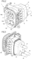
- Fig. 2 and 3 show the connector part 1.
- the connector part 1 is designed for installation on the vehicle 4, specifically as a vehicle inlet, e.g. in accordance with the CCS (Combined Charging System) Type 2.
- CCS Combined Charging System
- the connector part 1 is designed to transmit a charging current in the form of a direct current and/or in the form of an alternating current.
- the connector part 1 comprises a housing 10.
- the housing 10 encloses an interior space.
- the housing 10 comprises several housing parts 100, 101.
- a plug body 15 is mounted on the housing 10, which together with the housing 10 defines the interior space and in particular seals it against environmental influences, e.g. against moisture.
- the plug body 15 forms at least one plug section, in this case two plug sections 150A, 150B.
- the plug sections 150A, 150B are designed to be brought into engagement with corresponding plug sections of the mating connector part 3 for electrical contact.
- Two load contacts 11A, 11B in the form of plug contacts are used to set up a direct current circuit.
- the load contacts 11A, 11B are high-current load contacts. They can conduct currents of 50 A or more, in particular 100 A or more, during, in particular for the duration of a charging or discharging process. Further plug contacts are arranged on the other plug section 150B.
- the connector part 1 comprises in particular a protective conductor contact 12, which in this case is arranged on that plug section 150B. Additional (optional) plug contacts serve, for example, as alternating or three-phase contacts or as data connections.
- the connector part 1 comprises a Figures 4 to 13 shown and described in more detail below, which is arranged in the housing 10 and is electrically connected to the protective conductor contact 12, wherein the grounding element 13 extends in an electrically contactable manner along a creepage path between the two load contacts 11A, 11B.
- a correspondingly arranged earthing element can equally be provided alternatively or additionally in the mating connector part 3.
- cables 2A-2C are connected to the connector part 1.
- One of the cables 2A-2C is used for connection to one of the two load contacts 11A, 11B.
- Another cable 2C carries a protective conductor 20 that is electrically connected to the protective conductor contact 12.
- the connector part 1 forms a connector arrangement.
- some of the cables 2A-2C are combined to form a cable bundle.
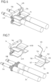
- Fig.4 shows the connector part 1 without the housing 10, so that part of the interior I of the connector part 1 defined by the housing 10 and the plug body 15 can be seen.
- the body 137 is electrically connected to the protective conductor contact 12.
- the body 137 is connected via a cable 135 to a connection connected to the protective conductor contact 12, to which a protective conductor 20 of the cable 2C is also electrically connected.
- the cable 135 is electrically connected to the body 137 via a screw terminal 134.
- the screw terminal 134 is arranged on the body 137, in particular firmly connected to it, e.g. welded to it.
- a contact carrier 14 is arranged in the interior I.
- the load contacts 11A, 11B are attached to the contact carrier 14.
- the contact carrier 14 is firmly connected to the plug body 15, e.g. screwed to it.
- the contact carrier 14 and the earthing element 13 are in engagement with each other.
- the shield sections 141A, 141B protrude from a mounting section 144.
- the mounting section 144 serves to mount the contact carrier 14 on the plug body 15.
- the mounting section 144 forms together with each of the shield sections 141A, 141B a receptacle 143A, 143B for each of the load contacts 11A, 11B, see in particular Fig. 8 and 9 .
- Each of the load contacts 11A, 11B can be inserted into one of the two receptacles 143A, 143B, in this case coming from opposite directions.
- the load contacts 11A, 11B each have a collar. The respective collar can be inserted into a corresponding recess (in the example shown on the mounting section 144 and in this case in the form of a circumferential groove) on the corresponding receptacle 143A, 143B in order to axially secure each of the load contacts 11A, 11B.
- the grounding element 13 further comprises a protruding section 130, which in the example shown is in the form of a knife.
- the protruding section 130 protrudes from the central section 133 and in the example shown represents an extension of the central section 133, which protrudes relative to the wing sections 131, 132.
- the protruding section 130 is flat and level.
- the protruding section 130 in the assembled state passes through an opening 140 in the contact carrier 14, in this case in the mounting section 144 of the contact carrier 14.
- the protruding section 130 passes through the opening 140 with respect to the (mutually parallel) alignment of the load contacts 11A, 11B in the axial direction.
- the protruding section 130 is arranged between the two receptacles 143A, 143B of the contact carrier 14 for the load contacts 11A, 11B.
- the protruding section 130 is arranged between the two load contacts 11A, 11B.
- the contact carrier 14 On both sides of the protruding section 130 of the grounding element 13, the contact carrier 14 has an insulation contour 142A, 142B.
- the insulation contours 142A, 142B each have two segments of circular cylinders with different radii arranged coaxially to one another. These segments are arranged in such a way that no water can collect in them during intended use, for which reason they are open at the sides and downwards in this case. The segments each form a part of the respective receptacle 143A, 143B.
- the insulation contours 142A, 142B serve to extend a creepage path between the two load contacts 11A, 11B, along which an electrical connection between the load contacts 11A, 11B could be established by moisture penetrating.
- the protruding section 130 of the grounding element 13 is arranged on this creepage path. In this way, a defective insulation between the two load contacts 11A, 11B can be reliably detected (e.g. by means of one of the insulation monitoring devices 41, 51).
- the insulation contours 142A, 142B protrude from the mounting section 144, specifically on a side opposite the shield sections 141A, 141B.
- Fig. 10 and 11 show in particular that the plug body 15 has insulation contours 151A, 151B.
- the insulation contours 151A, 151B are designed to match the insulation contours 142A, 142B of the contact carrier 14 so that they can be brought into engagement therewith and remain in the assembled state.
- the (DC) load contacts 11A, 11B are arranged closer to each other than each of the load contacts 11A, 11B is to the protective conductor contact 12. Furthermore, the load contacts 11A, 11B are arranged (in use) below the protective conductor contact 12.
- Fig. 12 and 13 show the assembled state of the connector part 1 in the cross-sectional view. It can be seen in particular that the insulation contours 142A, 142B, 151A, 151B of the contact carrier 14 and the plug body 15 are in engagement with one another, in this case in particular in an area between the two load contacts 11A, 11B. A kind of meandering course is formed.
- the protruding portion 130 extends between the respective engaging insulation contours 142A, 142B, 151A, 151B of the contact carrier 14 and the plug body 15.
- each of the load contacts 11A, 11B as well as a conductor of the respective cable 2A, 2B connected thereto is enclosed by a sheath 21, which is made, for example, of an insulating material.
- the shortest creepage path K between the load contacts 11A, 11B runs between the contact carrier 14 (in this case the mounting section 144 of the contact carrier 14) and the plug body 15.
- the earthing element 13 in particular the protruding section 130 of the earthing element 13, is arranged on the shortest creepage path K. This makes it particularly reliable to detect a lack of insulation.
- the body 137 of the grounding element 13 consists, for example, of metal or another electrically conductive material and can be electrically contacted by touching it (at any point), e.g. by water.
- the body 137 of the grounding element 13 is here formed in one piece, but can alternatively also be formed in several parts.
- the grounding element 13 also serves as a heat sink.
- a coolant e.g. it flows through it.
- the earthing element 13 designed and arranged as described can be used in the same way both in vehicle charging sockets and in charging plugs on charging stations.
Landscapes
- Engineering & Computer Science (AREA)
- Power Engineering (AREA)
- Transportation (AREA)
- Mechanical Engineering (AREA)
- Physics & Mathematics (AREA)
- General Physics & Mathematics (AREA)
- Details Of Connecting Devices For Male And Female Coupling (AREA)
- Connector Housings Or Holding Contact Members (AREA)
Claims (14)
- Partie de connecteur à enficher (1) destinée à la connexion électrique avec une partie de connecteur à enficher homologue (3), comprenant- un boîtier (10),- au moins deux contacts de charge (11A, 11B),- un porte-contacts (14) électriquement isolant, par lequel les contacts de charge (11A, 11B) sont maintenus au boîtier (10),- un contact de conducteur de protection (12) et- un élément de mise à la terre (13), qui est disposé dans le boîtier (10) et relié électriquement au contact de conducteur de protection (12),l'élément de mise à la terre (13) s'étendant de manière à pouvoir être mis en contact électrique au niveau d'un chemin de courant de fuite (K) entre les deux contacts de charge (11A, 11B),caractérisée en ce que l'élément de mise à la terre (13) comporte une lame (130) qui traverse une ouverture (140) dans le porte-contacts (14).
- Partie de connecteur à enficher (1) selon la revendication 1, caractérisée en ce que l'élément de mise à la terre (13) s'étend de manière à pouvoir être mis en contact électrique au niveau du chemin de courant de fuite le plus court (K) entre les deux contacts de charge (11A, 11B).
- Partie de connecteur à enficher (1) selon la revendication 1 ou 2, caractérisée en ce que l'élément de mise à la terre (13) s'étend entre les deux contacts de charge (11A, 11B).
- Partie de connecteur à enficher (1) selon l'une des revendications 1 à 3, caractérisée en ce que le porte-contacts (14) possède un contour d'isolation (142A, 142B) pour chacun des contacts de charge (11A, 11B), la lame (130) de l'élément de mise à la terre (13) s'étendant au moins par certaines portions entre les contours d'isolation (142A, 142B).
- Partie de connecteur à enficher (1) selon la revendication 4, caractérisée par un corps à enficher (15) qui, pour chacun des contacts de charge (11A, 11B), possède un contour d'isolation (151A, 151B), lequel est en prise avec le contour d'isolation (142A, 142B) du porte-contacts (14) pour le contact de charge (11A, 11B) respectif.
- Partie de connecteur à enficher (1) selon l'une des revendications 1 à 5, caractérisée en ce que le porte-contacts (14) possède, pour chaque contact de charge (11A, 11B), une portion de blindage (141A, 141B) destinée à l'isolation électrique de l'autre contact de charge (11A, 11B) respectif.
- Partie de connecteur à enficher (1) selon la revendication 6, caractérisée en ce que l'élément de mise à la terre (13) s'étend entre les portions de blindage (141A, 141B) et au moins partiellement autour des portions de blindage (141A, 141B).
- Partie de connecteur à enficher (1) selon l'une des revendications précédentes, caractérisée en ce qu'au moins une partie de l'élément de mise à la terre (13), dans le cas d'une utilisation de la partie de connecteur à enficher (1) avec la partie de connecteur à enficher homologue (3) conformément à sa destination, s'étend au niveau d'un endroit situé plus bas que les contacts de charge (11A, 11B).
- Partie de connecteur à enficher (1) selon l'une des revendications précédentes, caractérisée en ce que l'élément de mise à la terre (13) comporte un corps métallique (137).
- Partie de connecteur à enficher (1) selon la revendication 9, caractérisée en ce que le corps métallique (137) est relié électriquement au contact de conducteur de protection (12) par le biais d'un câble (135) .
- Partie de connecteur à enficher (1) selon l'une des revendications précédentes, caractérisée en ce que la partie de connecteur à enficher (1) est configurée pour conduire une puissance électrique de 10 kW ou plus.
- Partie de connecteur à enficher (1) selon l'une des revendications précédentes, caractérisée en ce que la partie de connecteur à enficher (1) est réalisée sous la forme d'une fiche de charge de véhicule destinée à la charge à courant fort en courant continu.
- Arrangement de charge destiné à charger et/ou décharger un véhicule électrique (4), caractérisé par la partie de connecteur à enficher (1) selon l'une des revendications précédentes et un dispositif de surveillance d'isolation (41), relié ou pouvant être relié au contact de conducteur de protection (12) de la partie de connecteur à enficher (1), lequel est conçu pour détecter une tension électrique appliquée au contact de conducteur de protection (12) par rapport à un potentiel de terre.
- Véhicule électrique (4), caractérisé par une partie de connecteur à enficher (1) selon l'une des revendications 1 à 12 ou par un arrangement de charge selon la revendication 13.
Applications Claiming Priority (2)
| Application Number | Priority Date | Filing Date | Title |
|---|---|---|---|
| DE102019120470.4A DE102019120470A1 (de) | 2019-07-30 | 2019-07-30 | Steckverbinder mit Isolationsüberwachung |
| PCT/EP2020/067279 WO2021018475A1 (fr) | 2019-07-30 | 2020-06-22 | Connecteur mâle avec surveillance d'isolation |
Publications (2)
| Publication Number | Publication Date |
|---|---|
| EP4005033A1 EP4005033A1 (fr) | 2022-06-01 |
| EP4005033B1 true EP4005033B1 (fr) | 2024-05-22 |
Family
ID=71130967
Family Applications (1)
| Application Number | Title | Priority Date | Filing Date |
|---|---|---|---|
| EP20734359.1A Active EP4005033B1 (fr) | 2019-07-30 | 2020-06-22 | Connecteur mâle avec surveillance d'isolation |
Country Status (4)
| Country | Link |
|---|---|
| US (1) | US12240342B2 (fr) |
| EP (1) | EP4005033B1 (fr) |
| DE (1) | DE102019120470A1 (fr) |
| WO (1) | WO2021018475A1 (fr) |
Cited By (1)
| Publication number | Priority date | Publication date | Assignee | Title |
|---|---|---|---|---|
| DE102024114514A1 (de) * | 2024-05-23 | 2025-11-27 | BRUGG eConnect AG | Steckervorrichtung, Stecker und Ladesystem |
Families Citing this family (10)
| Publication number | Priority date | Publication date | Assignee | Title |
|---|---|---|---|---|
| KR102807982B1 (ko) * | 2019-11-27 | 2025-05-14 | 엘에스이브이코리아 주식회사 | 전기차 충전용 커넥터 및 이를 포함하는 전기차 충전용 어셈블리 |
| DE102020125943A1 (de) * | 2020-10-05 | 2022-04-07 | Dr. Ing. H.C. F. Porsche Aktiengesellschaft | Verfahren zum Betrieb einer fahrzeugexternen Ladevorrichtung zum Laden eines Fahrzeugs und Ladevorrichtung |
| CN113173087B (zh) * | 2021-04-27 | 2022-12-23 | 奇瑞新能源汽车股份有限公司 | 电动汽车的充电插座及具有其的电动汽车 |
| DE102021206188A1 (de) * | 2021-06-17 | 2022-12-22 | Robert Bosch Gesellschaft mit beschränkter Haftung | Vorrichtung und Verfahren zum Kontaktieren eines Elektrofahrzeugs mit einer Ladestation und Ladestation |
| US20230085351A1 (en) * | 2021-09-10 | 2023-03-16 | Aptiv Technologies Limited | Serviceable power inlet connector |
| LU500693B1 (de) * | 2021-09-27 | 2023-03-27 | Phoenix Contact Gmbh & Co | Steckverbinderteil mit einer Schirmauflage |
| US12476393B2 (en) * | 2022-03-18 | 2025-11-18 | Aptiv Technologies AG | Hybrid electric charging inlet |
| DE102023101873A1 (de) * | 2023-01-26 | 2024-08-01 | Phoenix Contact E-Mobility Gmbh | Steckverbinderteil für ein Ladesystem zum Aufladen eines Elektrofahrzeugs |
| US12571824B2 (en) | 2024-01-19 | 2026-03-10 | HELLA GmbH & Co. KGaA | Method and system for monitoring impedance in a conductor |
| DE102024108757A1 (de) | 2024-03-27 | 2025-10-02 | Kiekert Aktiengesellschaft | Ladesteckverbinder für ein Elektro- oder Hybridfahrzeug |
Family Cites Families (7)
| Publication number | Priority date | Publication date | Assignee | Title |
|---|---|---|---|---|
| JP2509408Y2 (ja) * | 1990-08-31 | 1996-09-04 | 第一電子工業株式会社 | 電気コネクタ |
| JPH086390Y2 (ja) * | 1991-03-25 | 1996-02-21 | 日本航空電子工業株式会社 | コネクタ |
| US5266039A (en) * | 1992-11-13 | 1993-11-30 | General Electric Company | Electrical outlet receptacle |
| DE102013213336B4 (de) * | 2013-07-08 | 2024-02-01 | Te Connectivity Germany Gmbh | Elektrischer steckverbinder, ladedose und steckverbindersystem für ein elektro- oder hybridfahrzeug |
| FR3041172B1 (fr) * | 2015-09-11 | 2019-03-29 | Renault Sas | Dispositif amovible anti-claquage |
| DE102016105311A1 (de) * | 2016-03-22 | 2017-09-28 | Phoenix Contact E-Mobility Gmbh | Steckverbinderteil mit einem gekühlten Kontaktelement |
| DE102017215116A1 (de) | 2017-08-30 | 2019-02-28 | Heidelberger Druckmaschinen Ag | Kommunikation mit Ladekabel eines batterieelektrischen Fahrzeugs |
-
2019
- 2019-07-30 DE DE102019120470.4A patent/DE102019120470A1/de not_active Withdrawn
-
2020
- 2020-06-22 WO PCT/EP2020/067279 patent/WO2021018475A1/fr not_active Ceased
- 2020-06-22 EP EP20734359.1A patent/EP4005033B1/fr active Active
- 2020-06-22 US US17/628,576 patent/US12240342B2/en active Active
Cited By (1)
| Publication number | Priority date | Publication date | Assignee | Title |
|---|---|---|---|---|
| DE102024114514A1 (de) * | 2024-05-23 | 2025-11-27 | BRUGG eConnect AG | Steckervorrichtung, Stecker und Ladesystem |
Also Published As
| Publication number | Publication date |
|---|---|
| US12240342B2 (en) | 2025-03-04 |
| US20220250491A1 (en) | 2022-08-11 |
| WO2021018475A1 (fr) | 2021-02-04 |
| EP4005033A1 (fr) | 2022-06-01 |
| DE102019120470A1 (de) | 2021-02-04 |
Similar Documents
| Publication | Publication Date | Title |
|---|---|---|
| EP4005033B1 (fr) | Connecteur mâle avec surveillance d'isolation | |
| DE112017003853B4 (de) | Zwingenanordnung für einen elektrischen Verbinder | |
| DE102014017081A1 (de) | Anschlussanordnung zum elektrischen Kontaktieren eines Batteriemoduls, Koppelelement zum elektrischen Verbinden von Batteriemodulen, Batteriemodul, Batterie für ein Kraftfahrzeug und Kraftfahrzeug | |
| DE102014012320B3 (de) | Batteriemodul mit einer Mehrzahl von Batteriezellen und Batterie | |
| DE202017101060U1 (de) | Steckverbinder, insbesondere für eine Hochstromanwendung | |
| DE102009016756B4 (de) | Abschirmverbinderstruktur | |
| EP2606535B1 (fr) | Borne de traversée électrique murale | |
| EP2286489B1 (fr) | Connecteur d'une connexion enfichable | |
| DE102021117009B3 (de) | Steckverbindungseinrichtung und verfahren zum montieren einer steckverbindungseinrichtung | |
| WO2021001093A1 (fr) | Élément connecteur de charge refroidi de manière active | |
| DE102020211091A1 (de) | Elektrischer Kontaktverbinder sowie Batterie | |
| EP4089855A1 (fr) | Dispositif de contact pour un rail conducteur double et système de contact pour deux rails conducteurs doubles | |
| WO2023222615A1 (fr) | Dispositif et système pour vérifier la capacité de fonctionnement d'une station de charge | |
| DE112014002174T5 (de) | Verbinderstruktur für eine Leitung | |
| EP4089854B1 (fr) | Dispositif de contact pour un rail conducteur double, partie homologue au dispositif de contact et système de contact pour deux rails conducteurs doubles | |
| EP3756933B1 (fr) | Connecteur enfichable de charge et système de connexion enfichable de charge | |
| DE102023110642A1 (de) | Steckverbindungssystem und elektrifiziertes kraftfahrzeug mit einem solchen steckverbindungssystem | |
| AT521292B1 (de) | Leistungsbaugruppe mit definiertem Umladepfad und Verfahren zur Herstellung | |
| EP2732488A1 (fr) | Dispositif servant à guider un courant électrique | |
| EP2404339B1 (fr) | Dispositif de raccordement à courant de forte intensité pour accumulateur d'énergie | |
| EP4089853B1 (fr) | Connexion de rail conducteur de deux rails conducteurs doubles | |
| DE102011088402B4 (de) | Ladeeinrichtung mit elektrischem Steckverbinder für Elektrofahrzeug | |
| DE102023133830A1 (de) | Kontaktstecker, DC Kontakthalter und DC Trennstelle eines DC Steckers eines Ladekabels | |
| EP0773601A2 (fr) | Connexion enfichable de sécurité | |
| DE102023119078A1 (de) | Leistungskabelbaum mit Sammelschiene |
Legal Events
| Date | Code | Title | Description |
|---|---|---|---|
| STAA | Information on the status of an ep patent application or granted ep patent |
Free format text: STATUS: UNKNOWN |
|
| STAA | Information on the status of an ep patent application or granted ep patent |
Free format text: STATUS: THE INTERNATIONAL PUBLICATION HAS BEEN MADE |
|
| PUAI | Public reference made under article 153(3) epc to a published international application that has entered the european phase |
Free format text: ORIGINAL CODE: 0009012 |
|
| STAA | Information on the status of an ep patent application or granted ep patent |
Free format text: STATUS: REQUEST FOR EXAMINATION WAS MADE |
|
| 17P | Request for examination filed |
Effective date: 20220112 |
|
| AK | Designated contracting states |
Kind code of ref document: A1 Designated state(s): AL AT BE BG CH CY CZ DE DK EE ES FI FR GB GR HR HU IE IS IT LI LT LU LV MC MK MT NL NO PL PT RO RS SE SI SK SM TR |
|
| DAV | Request for validation of the european patent (deleted) | ||
| DAX | Request for extension of the european patent (deleted) | ||
| P01 | Opt-out of the competence of the unified patent court (upc) registered |
Effective date: 20230525 |
|
| P02 | Opt-out of the competence of the unified patent court (upc) changed |
Effective date: 20230530 |
|
| GRAP | Despatch of communication of intention to grant a patent |
Free format text: ORIGINAL CODE: EPIDOSNIGR1 |
|
| STAA | Information on the status of an ep patent application or granted ep patent |
Free format text: STATUS: GRANT OF PATENT IS INTENDED |
|
| INTG | Intention to grant announced |
Effective date: 20240122 |
|
| GRAS | Grant fee paid |
Free format text: ORIGINAL CODE: EPIDOSNIGR3 |
|
| GRAA | (expected) grant |
Free format text: ORIGINAL CODE: 0009210 |
|
| STAA | Information on the status of an ep patent application or granted ep patent |
Free format text: STATUS: THE PATENT HAS BEEN GRANTED |
|
| AK | Designated contracting states |
Kind code of ref document: B1 Designated state(s): AL AT BE BG CH CY CZ DE DK EE ES FI FR GB GR HR HU IE IS IT LI LT LU LV MC MK MT NL NO PL PT RO RS SE SI SK SM TR |
|
| REG | Reference to a national code |
Ref country code: GB Ref legal event code: FG4D Free format text: NOT ENGLISH |
|
| REG | Reference to a national code |
Ref country code: CH Ref legal event code: EP |
|
| REG | Reference to a national code |
Ref country code: DE Ref legal event code: R096 Ref document number: 502020008076 Country of ref document: DE |
|
| REG | Reference to a national code |
Ref country code: IE Ref legal event code: FG4D Free format text: LANGUAGE OF EP DOCUMENT: GERMAN |
|
| REG | Reference to a national code |
Ref country code: LT Ref legal event code: MG9D |
|
| REG | Reference to a national code |
Ref country code: NL Ref legal event code: MP Effective date: 20240522 |
|
| PG25 | Lapsed in a contracting state [announced via postgrant information from national office to epo] |
Ref country code: IS Free format text: LAPSE BECAUSE OF FAILURE TO SUBMIT A TRANSLATION OF THE DESCRIPTION OR TO PAY THE FEE WITHIN THE PRESCRIBED TIME-LIMIT Effective date: 20240922 |
|
| PG25 | Lapsed in a contracting state [announced via postgrant information from national office to epo] |
Ref country code: BG Free format text: LAPSE BECAUSE OF FAILURE TO SUBMIT A TRANSLATION OF THE DESCRIPTION OR TO PAY THE FEE WITHIN THE PRESCRIBED TIME-LIMIT Effective date: 20240522 |
|
| PG25 | Lapsed in a contracting state [announced via postgrant information from national office to epo] |
Ref country code: FI Free format text: LAPSE BECAUSE OF FAILURE TO SUBMIT A TRANSLATION OF THE DESCRIPTION OR TO PAY THE FEE WITHIN THE PRESCRIBED TIME-LIMIT Effective date: 20240522 Ref country code: HR Free format text: LAPSE BECAUSE OF FAILURE TO SUBMIT A TRANSLATION OF THE DESCRIPTION OR TO PAY THE FEE WITHIN THE PRESCRIBED TIME-LIMIT Effective date: 20240522 |
|
| PG25 | Lapsed in a contracting state [announced via postgrant information from national office to epo] |
Ref country code: GR Free format text: LAPSE BECAUSE OF FAILURE TO SUBMIT A TRANSLATION OF THE DESCRIPTION OR TO PAY THE FEE WITHIN THE PRESCRIBED TIME-LIMIT Effective date: 20240823 |
|
| PG25 | Lapsed in a contracting state [announced via postgrant information from national office to epo] |
Ref country code: PT Free format text: LAPSE BECAUSE OF FAILURE TO SUBMIT A TRANSLATION OF THE DESCRIPTION OR TO PAY THE FEE WITHIN THE PRESCRIBED TIME-LIMIT Effective date: 20240923 |
|
| PG25 | Lapsed in a contracting state [announced via postgrant information from national office to epo] |
Ref country code: NL Free format text: LAPSE BECAUSE OF FAILURE TO SUBMIT A TRANSLATION OF THE DESCRIPTION OR TO PAY THE FEE WITHIN THE PRESCRIBED TIME-LIMIT Effective date: 20240522 |
|
| PG25 | Lapsed in a contracting state [announced via postgrant information from national office to epo] |
Ref country code: ES Free format text: LAPSE BECAUSE OF FAILURE TO SUBMIT A TRANSLATION OF THE DESCRIPTION OR TO PAY THE FEE WITHIN THE PRESCRIBED TIME-LIMIT Effective date: 20240522 |
|
| PG25 | Lapsed in a contracting state [announced via postgrant information from national office to epo] |
Ref country code: PL Free format text: LAPSE BECAUSE OF FAILURE TO SUBMIT A TRANSLATION OF THE DESCRIPTION OR TO PAY THE FEE WITHIN THE PRESCRIBED TIME-LIMIT Effective date: 20240522 |
|
| PG25 | Lapsed in a contracting state [announced via postgrant information from national office to epo] |
Ref country code: LV Free format text: LAPSE BECAUSE OF FAILURE TO SUBMIT A TRANSLATION OF THE DESCRIPTION OR TO PAY THE FEE WITHIN THE PRESCRIBED TIME-LIMIT Effective date: 20240522 |
|
| PG25 | Lapsed in a contracting state [announced via postgrant information from national office to epo] |
Ref country code: PT Free format text: LAPSE BECAUSE OF FAILURE TO SUBMIT A TRANSLATION OF THE DESCRIPTION OR TO PAY THE FEE WITHIN THE PRESCRIBED TIME-LIMIT Effective date: 20240923 Ref country code: PL Free format text: LAPSE BECAUSE OF FAILURE TO SUBMIT A TRANSLATION OF THE DESCRIPTION OR TO PAY THE FEE WITHIN THE PRESCRIBED TIME-LIMIT Effective date: 20240522 Ref country code: NO Free format text: LAPSE BECAUSE OF FAILURE TO SUBMIT A TRANSLATION OF THE DESCRIPTION OR TO PAY THE FEE WITHIN THE PRESCRIBED TIME-LIMIT Effective date: 20240822 Ref country code: NL Free format text: LAPSE BECAUSE OF FAILURE TO SUBMIT A TRANSLATION OF THE DESCRIPTION OR TO PAY THE FEE WITHIN THE PRESCRIBED TIME-LIMIT Effective date: 20240522 Ref country code: LV Free format text: LAPSE BECAUSE OF FAILURE TO SUBMIT A TRANSLATION OF THE DESCRIPTION OR TO PAY THE FEE WITHIN THE PRESCRIBED TIME-LIMIT Effective date: 20240522 Ref country code: IS Free format text: LAPSE BECAUSE OF FAILURE TO SUBMIT A TRANSLATION OF THE DESCRIPTION OR TO PAY THE FEE WITHIN THE PRESCRIBED TIME-LIMIT Effective date: 20240922 Ref country code: HR Free format text: LAPSE BECAUSE OF FAILURE TO SUBMIT A TRANSLATION OF THE DESCRIPTION OR TO PAY THE FEE WITHIN THE PRESCRIBED TIME-LIMIT Effective date: 20240522 Ref country code: GR Free format text: LAPSE BECAUSE OF FAILURE TO SUBMIT A TRANSLATION OF THE DESCRIPTION OR TO PAY THE FEE WITHIN THE PRESCRIBED TIME-LIMIT Effective date: 20240823 Ref country code: FI Free format text: LAPSE BECAUSE OF FAILURE TO SUBMIT A TRANSLATION OF THE DESCRIPTION OR TO PAY THE FEE WITHIN THE PRESCRIBED TIME-LIMIT Effective date: 20240522 Ref country code: ES Free format text: LAPSE BECAUSE OF FAILURE TO SUBMIT A TRANSLATION OF THE DESCRIPTION OR TO PAY THE FEE WITHIN THE PRESCRIBED TIME-LIMIT Effective date: 20240522 Ref country code: BG Free format text: LAPSE BECAUSE OF FAILURE TO SUBMIT A TRANSLATION OF THE DESCRIPTION OR TO PAY THE FEE WITHIN THE PRESCRIBED TIME-LIMIT Effective date: 20240522 Ref country code: RS Free format text: LAPSE BECAUSE OF FAILURE TO SUBMIT A TRANSLATION OF THE DESCRIPTION OR TO PAY THE FEE WITHIN THE PRESCRIBED TIME-LIMIT Effective date: 20240822 |
|
| PG25 | Lapsed in a contracting state [announced via postgrant information from national office to epo] |
Ref country code: DK Free format text: LAPSE BECAUSE OF FAILURE TO SUBMIT A TRANSLATION OF THE DESCRIPTION OR TO PAY THE FEE WITHIN THE PRESCRIBED TIME-LIMIT Effective date: 20240522 |
|
| PG25 | Lapsed in a contracting state [announced via postgrant information from national office to epo] |
Ref country code: EE Free format text: LAPSE BECAUSE OF FAILURE TO SUBMIT A TRANSLATION OF THE DESCRIPTION OR TO PAY THE FEE WITHIN THE PRESCRIBED TIME-LIMIT Effective date: 20240522 |
|
| PG25 | Lapsed in a contracting state [announced via postgrant information from national office to epo] |
Ref country code: CZ Free format text: LAPSE BECAUSE OF FAILURE TO SUBMIT A TRANSLATION OF THE DESCRIPTION OR TO PAY THE FEE WITHIN THE PRESCRIBED TIME-LIMIT Effective date: 20240522 |
|
| PG25 | Lapsed in a contracting state [announced via postgrant information from national office to epo] |
Ref country code: SK Free format text: LAPSE BECAUSE OF FAILURE TO SUBMIT A TRANSLATION OF THE DESCRIPTION OR TO PAY THE FEE WITHIN THE PRESCRIBED TIME-LIMIT Effective date: 20240522 Ref country code: RO Free format text: LAPSE BECAUSE OF FAILURE TO SUBMIT A TRANSLATION OF THE DESCRIPTION OR TO PAY THE FEE WITHIN THE PRESCRIBED TIME-LIMIT Effective date: 20240522 |
|
| PG25 | Lapsed in a contracting state [announced via postgrant information from national office to epo] |
Ref country code: SM Free format text: LAPSE BECAUSE OF FAILURE TO SUBMIT A TRANSLATION OF THE DESCRIPTION OR TO PAY THE FEE WITHIN THE PRESCRIBED TIME-LIMIT Effective date: 20240522 |
|
| PG25 | Lapsed in a contracting state [announced via postgrant information from national office to epo] |
Ref country code: SM Free format text: LAPSE BECAUSE OF FAILURE TO SUBMIT A TRANSLATION OF THE DESCRIPTION OR TO PAY THE FEE WITHIN THE PRESCRIBED TIME-LIMIT Effective date: 20240522 Ref country code: SK Free format text: LAPSE BECAUSE OF FAILURE TO SUBMIT A TRANSLATION OF THE DESCRIPTION OR TO PAY THE FEE WITHIN THE PRESCRIBED TIME-LIMIT Effective date: 20240522 Ref country code: RO Free format text: LAPSE BECAUSE OF FAILURE TO SUBMIT A TRANSLATION OF THE DESCRIPTION OR TO PAY THE FEE WITHIN THE PRESCRIBED TIME-LIMIT Effective date: 20240522 Ref country code: EE Free format text: LAPSE BECAUSE OF FAILURE TO SUBMIT A TRANSLATION OF THE DESCRIPTION OR TO PAY THE FEE WITHIN THE PRESCRIBED TIME-LIMIT Effective date: 20240522 Ref country code: DK Free format text: LAPSE BECAUSE OF FAILURE TO SUBMIT A TRANSLATION OF THE DESCRIPTION OR TO PAY THE FEE WITHIN THE PRESCRIBED TIME-LIMIT Effective date: 20240522 Ref country code: CZ Free format text: LAPSE BECAUSE OF FAILURE TO SUBMIT A TRANSLATION OF THE DESCRIPTION OR TO PAY THE FEE WITHIN THE PRESCRIBED TIME-LIMIT Effective date: 20240522 |
|
| REG | Reference to a national code |
Ref country code: CH Ref legal event code: PL |
|
| PG25 | Lapsed in a contracting state [announced via postgrant information from national office to epo] |
Ref country code: MC Free format text: LAPSE BECAUSE OF FAILURE TO SUBMIT A TRANSLATION OF THE DESCRIPTION OR TO PAY THE FEE WITHIN THE PRESCRIBED TIME-LIMIT Effective date: 20240522 Ref country code: IT Free format text: LAPSE BECAUSE OF FAILURE TO SUBMIT A TRANSLATION OF THE DESCRIPTION OR TO PAY THE FEE WITHIN THE PRESCRIBED TIME-LIMIT Effective date: 20240522 |
|
| PG25 | Lapsed in a contracting state [announced via postgrant information from national office to epo] |
Ref country code: LU Free format text: LAPSE BECAUSE OF NON-PAYMENT OF DUE FEES Effective date: 20240622 |
|
| REG | Reference to a national code |
Ref country code: DE Ref legal event code: R097 Ref document number: 502020008076 Country of ref document: DE |
|
| PLBE | No opposition filed within time limit |
Free format text: ORIGINAL CODE: 0009261 |
|
| STAA | Information on the status of an ep patent application or granted ep patent |
Free format text: STATUS: NO OPPOSITION FILED WITHIN TIME LIMIT |
|
| PG25 | Lapsed in a contracting state [announced via postgrant information from national office to epo] |
Ref country code: IE Free format text: LAPSE BECAUSE OF NON-PAYMENT OF DUE FEES Effective date: 20240622 |
|
| GBPC | Gb: european patent ceased through non-payment of renewal fee |
Effective date: 20240822 |
|
| PG25 | Lapsed in a contracting state [announced via postgrant information from national office to epo] |
Ref country code: SI Free format text: LAPSE BECAUSE OF FAILURE TO SUBMIT A TRANSLATION OF THE DESCRIPTION OR TO PAY THE FEE WITHIN THE PRESCRIBED TIME-LIMIT Effective date: 20240522 Ref country code: CH Free format text: LAPSE BECAUSE OF NON-PAYMENT OF DUE FEES Effective date: 20240630 Ref country code: BE Free format text: LAPSE BECAUSE OF NON-PAYMENT OF DUE FEES Effective date: 20240630 |
|
| PG25 | Lapsed in a contracting state [announced via postgrant information from national office to epo] |
Ref country code: FR Free format text: LAPSE BECAUSE OF NON-PAYMENT OF DUE FEES Effective date: 20240722 |
|
| 26N | No opposition filed |
Effective date: 20250225 |
|
| REG | Reference to a national code |
Ref country code: BE Ref legal event code: MM Effective date: 20240630 |
|
| PG25 | Lapsed in a contracting state [announced via postgrant information from national office to epo] |
Ref country code: GB Free format text: LAPSE BECAUSE OF NON-PAYMENT OF DUE FEES Effective date: 20240822 |
|
| PGFP | Annual fee paid to national office [announced via postgrant information from national office to epo] |
Ref country code: AT Payment date: 20250721 Year of fee payment: 5 |
|
| PG25 | Lapsed in a contracting state [announced via postgrant information from national office to epo] |
Ref country code: SE Free format text: LAPSE BECAUSE OF FAILURE TO SUBMIT A TRANSLATION OF THE DESCRIPTION OR TO PAY THE FEE WITHIN THE PRESCRIBED TIME-LIMIT Effective date: 20240522 |
|
| PGFP | Annual fee paid to national office [announced via postgrant information from national office to epo] |
Ref country code: DE Payment date: 20250827 Year of fee payment: 6 |
|
| PG25 | Lapsed in a contracting state [announced via postgrant information from national office to epo] |
Ref country code: CY Free format text: LAPSE BECAUSE OF FAILURE TO SUBMIT A TRANSLATION OF THE DESCRIPTION OR TO PAY THE FEE WITHIN THE PRESCRIBED TIME-LIMIT; INVALID AB INITIO Effective date: 20200622 |
|
| PG25 | Lapsed in a contracting state [announced via postgrant information from national office to epo] |
Ref country code: HU Free format text: LAPSE BECAUSE OF FAILURE TO SUBMIT A TRANSLATION OF THE DESCRIPTION OR TO PAY THE FEE WITHIN THE PRESCRIBED TIME-LIMIT; INVALID AB INITIO Effective date: 20200622 |