EP4005368B1 - Feuille allongée pour recouvrir des plantes agricoles cultivées - Google Patents
Feuille allongée pour recouvrir des plantes agricoles cultivées Download PDFInfo
- Publication number
- EP4005368B1 EP4005368B1 EP21206952.0A EP21206952A EP4005368B1 EP 4005368 B1 EP4005368 B1 EP 4005368B1 EP 21206952 A EP21206952 A EP 21206952A EP 4005368 B1 EP4005368 B1 EP 4005368B1
- Authority
- EP
- European Patent Office
- Prior art keywords
- film
- sheet
- cover film
- ventilation
- area
- Prior art date
- Legal status (The legal status is an assumption and is not a legal conclusion. Google has not performed a legal analysis and makes no representation as to the accuracy of the status listed.)
- Active
Links
Images







Classifications
-
- A—HUMAN NECESSITIES
- A01—AGRICULTURE; FORESTRY; ANIMAL HUSBANDRY; HUNTING; TRAPPING; FISHING
- A01G—HORTICULTURE; CULTIVATION OF VEGETABLES, FLOWERS, RICE, FRUIT, VINES, HOPS OR SEAWEED; FORESTRY; WATERING
- A01G13/00—Protection of plants
- A01G13/20—Protective coverings for plants
-
- A—HUMAN NECESSITIES
- A01—AGRICULTURE; FORESTRY; ANIMAL HUSBANDRY; HUNTING; TRAPPING; FISHING
- A01G—HORTICULTURE; CULTIVATION OF VEGETABLES, FLOWERS, RICE, FRUIT, VINES, HOPS OR SEAWEED; FORESTRY; WATERING
- A01G13/00—Protection of plants
- A01G13/20—Protective coverings for plants
- A01G13/21—Protective coverings for plants providing overhead protection, i.e. canopies
-
- A—HUMAN NECESSITIES
- A01—AGRICULTURE; FORESTRY; ANIMAL HUSBANDRY; HUNTING; TRAPPING; FISHING
- A01G—HORTICULTURE; CULTIVATION OF VEGETABLES, FLOWERS, RICE, FRUIT, VINES, HOPS OR SEAWEED; FORESTRY; WATERING
- A01G13/00—Protection of plants
- A01G13/20—Protective coverings for plants
- A01G13/24—Tunnels for covering rows of plants
-
- A—HUMAN NECESSITIES
- A01—AGRICULTURE; FORESTRY; ANIMAL HUSBANDRY; HUNTING; TRAPPING; FISHING
- A01G—HORTICULTURE; CULTIVATION OF VEGETABLES, FLOWERS, RICE, FRUIT, VINES, HOPS OR SEAWEED; FORESTRY; WATERING
- A01G9/00—Cultivation in receptacles, forcing-frames or greenhouses; Edging for beds, lawn or the like
- A01G9/14—Greenhouses
- A01G9/1438—Covering materials therefor; Materials for protective coverings used for soil and plants, e.g. films, canopies, tunnels or cloches
-
- Y—GENERAL TAGGING OF NEW TECHNOLOGICAL DEVELOPMENTS; GENERAL TAGGING OF CROSS-SECTIONAL TECHNOLOGIES SPANNING OVER SEVERAL SECTIONS OF THE IPC; TECHNICAL SUBJECTS COVERED BY FORMER USPC CROSS-REFERENCE ART COLLECTIONS [XRACs] AND DIGESTS
- Y02—TECHNOLOGIES OR APPLICATIONS FOR MITIGATION OR ADAPTATION AGAINST CLIMATE CHANGE
- Y02A—TECHNOLOGIES FOR ADAPTATION TO CLIMATE CHANGE
- Y02A40/00—Adaptation technologies in agriculture, forestry, livestock or agroalimentary production
- Y02A40/10—Adaptation technologies in agriculture, forestry, livestock or agroalimentary production in agriculture
- Y02A40/25—Greenhouse technology, e.g. cooling systems therefor
Definitions
- the present invention relates to an elongated sheet for covering agricultural cultivated plants, for example vegetable and/or fruit plants or herbs.
- the cover comprises an elongated basic film made of plastic.
- Elongated sheets of the aforementioned type are known from practice and are in particular placed on supporting posts, a frame or rack and can be fixed with ropes (or tension ropes) or otherwise.
- the elongated sheet can configure a gable roof for the cultivated plants underneath.
- the elongated sheet can be used in foil tunnels.
- Foil tunnels may comprise a framework, which is usually made of steel. This framework can in particular have round arches or metal tubes bent in a semicircle, on which the sheet can then be laid.
- foil tunnels can comprise connecting rods and a tunnel-shaped framework that can be covered with the sheet.
- the foil or elongated sheet is secured to the ground and/or the framework in particular to prevent wind blowing.
- the elongated sheet can extend to the ground or a distance to the ground can be provided, in particular if the sheet is attached to the framework.
- Prior art foil tunnels or greenhouses may comprise openings, such as doors or the like, which can be closed as required.
- a foil tunnel may be configured to be open or closed at the front sides. Foils or the elongated sheet itself can also be used to close the foil tunnel.
- the sheet is used to take advantage of the greenhouse effect. This is based on the fact that due to the in particular translucent cover and/or sheet, an area protected from the weather can be created for the cultivated plants.
- the area or greenhouse climate can also be configured in such a way that there is an increase in temperature and humidity compared to the weather conditions outside the greenhouse.
- the ventilation area can comprise a plurality of ventilation openings that can ensure air exchange.
- a state of the art agricultural cover with ventilation openings which are covered by a film is known GR 1 004 440 B .
- the object of the present invention is to remedy this situation.
- the aforementioned object is at least substantially solved by an elongated sheet for covering agricultural crops, in particular for a greenhouse, for generating a greenhouse climate, which can also be referred to as subclimate and/or greenhouse climate, in the covered area, wherein the elongated sheet comprises an elongated basic film made of plastic. Furthermore, a ventilation area extending in longitudinal sheet direction and having a plurality of ventilation openings is provided in the central area of the basic film.
- a cover film made of plastic, in particular an elongated one, extending in the longitudinal sheet direction of the basic film, is applied to the ventilation area to produce free spaces for air exchange and is firmly welded to the basic film via a plurality of connection areas following one another in the longitudinal sheet direction.
- the cover film serves in particular to cover the ventilation openings, more preferably completely.
- the material and/or the nature and/or the quality of the cover film is selected in such a way that the cover film, in particular in the state of use, in a first state lies flat against or on the upper side of the construction film at least substantially in the region of the free spaces and, preferably by convection of the heated air in the covered region, in a second state lifts off at least in regions relative to the upper side of the basic film forming free spaces between the upper side of the basic film and the underside of the cover film, wherein the first state is maintained up to a transition temperature T 1 of the greenhouse climate and wherein the second state is obtained and/or realized above the transition temperature T 1 of the greenhouse climate.
- the cover film is in contact with the upper side of the basic film up to the transition temperature T 1 , wherein at a temperature T in the covered region above the transition temperature T 1 the cover film lifts off relative to the upper side of the basic film with production of free spaces at least in some regions.
- the cover film and the material of the cover film is configured to be more elastic and softer and less rigid than the basic film and the material of the basic film and that the cover film comprises a lower grammage than the basic film.
- the outstanding advantage is that, according to the invention, a self-regulating system can be ensured with regard to the air ventilation in the covered area.
- This configuration according to the invention leads to improved ventilation.
- the material of the cover film is designed in such a way that ultimately at least the two described states can be configured in the state of use of the sheet and/or cover.
- the state of use represents a so-called “ideal state”.
- further external weather influences in addition to the outside temperature, such as wind and/or rain and/or moist surfaces, are more preferably to be disregarded.
- the “ideal state” describes in particular an at least substantially windless and dry state of use of the cover film.
- the use condition contemplates that the sheet is used to cover cultivated plants - for example, if the sheet is used to cover a greenhouse and/or foil tunnel.
- the sheet is used to cover cultivated plants - for example, if the sheet is used to cover a greenhouse and/or foil tunnel.
- open areas of the respective foil tunnel of the greenhouse may also be provided.
- the foil tunnel can be configured to be open at the front sides. There may also be a gap between the cover or sheet and the ground, in particular if the sheet is placed on a framework or the like.
- the sheet when used in a greenhouse or for covering a greenhouse, it may be provided that further ventilation openings, such as doors or the like, are present.
- the transition temperature T 1 refers in particular to the temperature of the greenhouse climate. It is understood that the temperature of the greenhouse climate is not measured and/or determined at the further openings, such as, for example, at the opened front sides of the foil tunnel and/or at the further ventilation openings of the greenhouse, but in the central, covered area, preferably at least substantially below the sheet. Thus, it can be provided that the transition temperature T 1 is measured and/or determined in the center of the sheet, for example with a deviation of +/- 30 %, in relation to the longitudinal sheet direction.
- the distance between the temperature measuring point and the underside of the sheet facing the cultivated plants can be less than 3 m, preferably less than 2 m, more preferably less than 1 m.
- transition temperature T 1 of the greenhouse climate is influenced by the external temperature outside the covered area.
- cover film It is described at least one material property of the cover film which makes it possible for the material of the cover film to be configured in such a way that, due to the different properties between the cover film and the basic film, it can be achieved that the cover film fits and/or clings against the ventilation openings (in particular to close them) if ventilation is not yet required in the covered region. This is ultimately achieved in particular by at least one different material composition of the cover film and the basic film.
- the self-regulating configuration of the ventilation underneath the cover according to the invention can make it possible that no excessively high or low temperatures of the greenhouse climate occur, which would otherwise have a detrimental effect and/or a harmful effect on the cultivation of the cultivated plants.
- the elongated sheet can be used to take advantage of the greenhouse effect. Similar to the atmospheric greenhouse effect, solar radiation can thereby penetrate the covered area and heat it. The converted heat is subsequently distributed by convection of the heated air and in particular also by infrared radiation.
- the sheet according to the invention thus makes it possible for at least a large part of the rising warm air to be "trapped" inside and/or in the covered area.
- the sheet provides a barrier to convection, preventing the rising air mass from exiting the covered area.
- the ventilation openings of the invention ensure that ventilation is still possible to maintain optimal growing conditions.
- the cover also protects the cultivated plants from precipitation and/or heavy rain and thus improves the growing conditions for the cultivated plants.
- a regulation of the greenhouse climate can be achieved.
- the sheet according to the invention is used for warm houses, which are operated more preferably at temperatures above 18 °C.
- internal temperatures of the greenhouse climate of more than 50 °C, preferably of more than 45 °C can be at least substantially reliably avoided, in particular provided that the external temperature and/or outside temperature remains below 50 °C, preferably below 40 °C.
- the ventilation openings of the ventilation areas serve in particular to ventilate and/or deventilate the covered area.
- the ventilation openings of the ventilation area according to the invention are provided in the roof area of the foil tunnel and/or the greenhouse.
- the ventilation openings of the ventilation area can provide a so-called roof ventilation area.
- roof ventilation area it is understood that when the sheet is used as a greenhouse cover, other open areas of the greenhouse may also be provided.
- a longitudinal area for example a continuous one, and/or window openings can be configured in the area of the side surfaces of the foil tunnel.
- a ventilation opening can also be provided in the area of the front sides of the foil tunnel. Further ventilation openings can improve the valve system.
- the cover film can extend continuously in the longitudinal sheet direction and/or over the entire length of the basic film.
- the cover film is especially designed to completely cover the ventilation area.
- the cover film can overlap the ventilation area with its edge area, especially at least on one side (in relation to the longitudinal edge of the basic film), even more preferably on both sides.
- the cover film comprises individual sections which preferably adjoin one another afterwards and/or are arranged to overlap one another.
- the individual sections of the cover film are especially designed at least essentially to cover the ventilation area. Especially the ventilation openings are covered and/or obscured by the cover film.
- the ventilation area comprises a plurality of neighbouring ventilation sections arranged one behind the other in the longitudinal sheet direction.
- Especially one ventilation section comprises at least one ventilation opening.
- all ventilation openings are arranged in ventilation sections, preferably grouped together. In this way the ventilation sections can each represent a grouped arrangement of ventilation openings.
- the ventilation sections can be provided over the entire longitudinal sheet direction and can be covered especially by the cover film.
- the ventilation area can comprise two ventilation segments, preferably mirror-symmetrical to each other, which are opposite each other at least in some areas.
- the ventilation segments can be designed especially in longitudinal direction.
- the basic film can comprise at least two longitudinal segments on which the respective ventilation segments can be arranged. The ventilation segments of the longitudinal segments can thereby be arranged in the central area of the basic film and especially facing each other.
- the sheet is used as a gable roof, for example.
- the separating line separating the ventilation segments and/or the longitudinal segments of the basic film, which preferably forms the centre line of the sheet is placed on a tension cable, frame and/or at least one support post.
- the ventilation of the covered area can be ensured in the area of the ridge of the gable roof and/or over the central area of the sheet.
- the hot and/or humid air of the covered area of the cultivated plants accumulates, which can escape via the ventilation openings.
- a fresh air supply can be provided at the same time.
- the mirror axis can be designed by the longitudinal axis of the sheet and/or by the separating line.
- the mirror axis can also be the axis defined by the support on a tension cable and/or support means, such as a bar of a frame.
- a ventilation section is framed by at least two connecting sections and/or weldings.
- a ventilation section can be enclosed by two weldings.
- the sloping design of a connection area can be provided, especially on both sides of the ventilation sections.
- the cover film and/or the basic film comprises as material polyethylene, preferably low-density polyethylene (LDPE), and/or consists thereof.
- Polyethylene is a material that can be used for producing films.
- Polyethylene, in particular LDPE is characterized by high chemical resistance and good electrical insulation properties.
- the use of polyethylene as a material for the cover film and/or the basic film therefore makes it possible to provide a low-cost sheet for covering agricultural cultivated plants.
- a polyethylene film is also characterized by good light transmission, while at the same time offering protection against UV radiation in particular.
- Polyethylene film, which in particular can be used as a cover film and/or basic film is also preferably configured to be robust.
- the cover film comprises the same material as the basic film.
- the cover film comprises further additives, in particular plasticizers, which in particular are not contained in the basic film and/or are contained at a different concentration in the basic film.
- both the cover film and the basic film can comprise polyethylene as the material, wherein the cover film can comprise further and/or other material additives compared to the basic film.
- the materials of the cover film and the basic film differ from one another.
- the material of the cover film is selected as a function of the material of the basic film in such a way that the ventilation behavior according to the invention, which in particular ensures the self-regulating ventilation system, can be achieved.
- the cover film and/or the basic film comprises an additional material made of plastic and/or an additional material made of a polymer.
- the additive material may include ethylene vinyl acetate copolymer (EVA), linear low density polyethylene (LLDPE), high density polyethylene (HDPE) and/or medium density polyethylene (MDPE), and/or mixtures thereof.
- EVA ethylene vinyl acetate copolymer
- LLDPE linear low density polyethylene
- HDPE high density polyethylene
- MDPE medium density polyethylene
- the aforementioned additional materials make it possible to further improve the nature and/or quality of the film material for the cover film and/or the basic film, and in particular to optimize it for the condition of use.
- the aforementioned additional material can influence the stiffness and/or the softness and/or the density and/or the grammage of the respective film in a manner advantageous for the invention. Films with a low density and/or with a low grammage are characterized in particular by reduced material consumption and are thus preferred for ecological reasons.
- cover film and preferably the basic film too are formed as a single layer.
- the single-layer configuration of the aforementioned films makes it possible to provide a cost-effective sheet for covering agricultural cultivated plants.
- the basic film comprise a multilayer structure.
- different materials in particular with different properties and/or functions, can be used in the multiple layers.
- a multilayer material can also have the advantage of increasing the robustness of the the basic film, so that in particular use under adverse weather conditions can be ensured.
- the nature and/or quality, in particular the texture and/or the layer structure, of the basic film differs from that of the cover film.
- the cover film can comprise a smaller layer thickness than the basic film.
- the layer thickness means the total layer thickness. The lower layer thickness can ensure that the cover film can provide the ventilation properties of the sheet according to the invention in the state of use by being applied and reapplied to the ventilation openings.
- cover film and/or the basic film can be used to ensure laying and/or placing of the cover film to the ventilation area, in particular for closing the openings.
- the cover film can be configured as a monoaxially or biaxially stretched film web.
- Monoaxially stretched means in particular that the film has been stretched on one side (mono) in the machine direction, preferably after extrusion, and is thus preferably very tear-resistant and in particular no longer expands in this direction.
- Biaxial stretching makes it possible to further increase the tensile strength, since stretching has previously taken place in the transverse and longitudinal directions.
- biaxial stretching can increase the cohesion of the molecules so that they are entangled with one another and thus significantly improved mechanical properties can be achieved.
- the cover film can be made of the same material and/or material combination as the basic film, but comprise a grammage than the basic film due to the monoaxial or biaxial stretching. Thus, the stretching can ensure the different properties of the cover film and the basic film in the state of use.
- the cover film comprises an embossing and/or is configured to be embossed.
- the embossing can be introduced into the cover film by means of pressure, preferably pressing, and/or by means of heat.
- the embossing of the cover film can achieve a three-dimensional deformation of the cover film.
- the embossing can give the cover film such a texture and/or condition and/or quality that the stiffness of the cover film can be reduced.
- the cover film comprises and/or consists of very low density polyethylene (VLDPE), ultra low density polyethylene (ULDPE), a plastomeric material and/or mixtures thereof.
- VLDPE very low density polyethylene
- ULDPE ultra low density polyethylene
- a plastomeric material e.g., a plastomeric material
- the aforementioned materials particularly ensure the configuration of a soft and/or elastic cover film.
- the material of the cover film is softer than that of the basic film, wherein it can be achieved by the aforementioned materials and/or the addition of the aforementioned materials that the cover film is configured softer than the basic film.
- the mechanical properties of the cover film and/or the basic film with regard to the necessary stability can be maintained by the aforementioned materials.
- the basic film comprises a width of between 0,5 and 40 m, preferably between 1 and 20 m, more preferably between 1.5 and 15 m.
- the aforementioned widths are, in particular, standard widths in the prior art for a cover or a sheet for use as a greenhouse film, in particular for foil tunnels.
- the width of the cover film can be configured smaller than the width of the basic film. This results from the mere fact that the cover film is only used to cover the central area of the basic film where the ventilation area is provided.
- the cover foil may further preferably comprise a width of at least 10 cm, preferably between 10 cm to 2 m, more preferably greater than 50 cm, preferably between 100 cm to 150 cm.
- the sheet can preferably comprise a length of at least 1 m, more preferably between 2 to 1000 m, more preferably between 10 to 800 m.
- the length of the sheet can in particular be configured depending on the use.
- the sheet can be provided to the user as roll material. The user can then use the sheet as required for the particular cultivation - i.e. for a greenhouse, foil tunnel and/or for other constructions to cover the cultivated plants.
- the distance between two weldings and/or connection areas immediately adjacent in longitudinal sheet direction between the basic film and the cover film is at least 5 cm, preferably at least 20 cm, more preferably between 25 to 60 cm.
- the connection areas and/or the weldings are at least substantially regularly spaced and each configure a free space therebetween.
- the free space has a length, preferably a maximum length, extending in longitudinal sheet direction of at least 5 cm, more preferably between 25 to 50 cm.
- a plurality of ventilation openings may be arranged in the free space.
- the cover film comprises a layer thickness of at least 50 ⁇ m, more preferably between 60 to 300 ⁇ m, more preferably between 150 to 200 ⁇ m.
- the layer thicknesses of the aforementioned type make it possible to provide both a stable and a soft cover film at the same time, which can enable self-regulation of the ventilation of the greenhouse climate due to its material properties.
- the cover film can comprise a grammage of at least 20 g/m 2 , preferably between 50 to 500 g/m 2 , more preferably between 110 to 180 g/m 2 . Also, grammages of the type mentioned above make it possible to ensure that the cover film can be used in accordance with the invention.
- the basic film can preferably comprise a greater layer thickness than the cover film and/or a higher basis weight than the cover film.
- the basic film comprises a layer thickness of at least 70 ⁇ m, preferably between 80 and 350 ⁇ m, more preferably between 200 and 300 ⁇ m.
- the basic film comprises a grammage of at least 50 g/m 2 , more preferably between 100 to 800 g/m 2 , more preferably between 200 to 250 g/m 2 .
- the transition temperature T 1 is greater than 20 °C, preferably greater than 30 °C, more preferably between 30 to 50 °C and in particular 38 °C +/-5 °C.
- Transition temperatures T 1 of the aforementioned type make it possible to provide an optimal temperature for the cultivation of the cultivated plants for the greenhouse climate.
- different transition temperatures T 1 can be provided by selecting the texture and/or the nature and/or the quality of the cover film.
- the transition temperature T 1 in the state of use also results depending on the outside temperature and depending on the size or the number of further ventilation openings.
- the aforementioned transition temperature T 1 presupposes in particular that there is at least substantially complete covering of the cultivated plants, in particular complete covering of the greenhouse or the foil tunnel by the sheet according to the invention, so that an initially substantially closed and/or enclosed space results.
- the aforementioned transition temperature T 1 assumes that it is measured in particular in the central area in relation to the longitudinal sheet direction, preferably in a range of +/- 30% starting from the geometric center of the length of the sheet.
- At least one ventilation opening in particular all ventilation openings of the ventilation area(s), comprises a maximum diameter of at least 3 mm, preferably at least 30 mm, more preferably between 50 to 100 mm. Diameters of the aforementioned type more preferably allow a sufficiently high air exchange of the covered area and can also be closed and/or covered by the cover film.
- the sum of the areas of all ventilation openings corresponds to at least 1 %, preferably between 1.1 % and 3 %, even more preferably between 1.3 % and 2 %, of the total area of the basic film.
- connection area is preferably designed to be inclined and/or oblique with respect to a weld start point and a weld end point in relation to the cross direction running orthogonally to the longitudinal sheet direction.
- connection area straight and/or with straight and/or parallel weldings, in particular with respect to a weld start point and a weld end point in relation to the cross direction running orthogonally to the longitudinal sheet direction.
- the weldings can be at least substantially parallel to the cross direction of the sheet.
- the self-regulating system can preferably be reached independent from the form of the weldings.
- the inclination and/or oblique arrangement between the weld start point and the weld end point is to be understood in particular as meaning that the line connecting the weld start point with the weld end point, especially an "imaginary" line, is arranged inclined and/or angled and/or oblique with respect to the cross direction.
- the free spaces are each provided above a ventilation section and/or the connection areas are designed in such a way that the free space tapers towards a longitudinal edge of the sheet, especially a longitudinal edge of the basic film.
- such free space can be provided which comprises a narrowing shape due to the inclination of the connection area with respect to the cross direction. According to the invention, it has been found that this can ensure better ventilation and/or deaeration of the covered area. If the line connecting the weld start point with the weld end point had been arranged at least essentially in the cross direction of the sheet, a corrugated arrangement of the cover film on the basic film to form free spaces would have been possible, but these free spaces could not ensure a tapering of the covered area compared to an inclined connection area.
- the weld start point is the outermost point of the connection area facing a first longitudinal edge of the sheet, especially wherein the weld end point is the outermost end point of the connection area facing the further longitudinal edge of the basic film opposite the first longitudinal edge.
- the geometry of the connection area allows the elongation to be applied at lower levels near the weld end point and at higher levels near the weld start point. This results in the free space and/or cover film in the area between neighbouring connection areas being widened so that air can escape more easily.
- connection area can be designed especially symmetrically, preferably mirror-symmetrically, or not symmetrically in relation to the cross direction.
- the connection area can be composed of two or more components.
- the connection area can also comprise continuous, punctual or interrupted individual welding sections.
- the line connecting the weld start point with the weld end point encloses an angle of at least 5° to the cross direction.
- the aforementioned angle is between 5° and 70°, even more preferably between 30° and 50°.
- the line connecting the weld start point with the weld end point does not have to be designed as a weld line or section - but it can be.
- the weld start point is a weld point and/or lies on a weld line.
- the weld end point is also a weld point and lies on the same weld line as the weld start point, on a further weld line and/or a further weld section.
- the weld line of the weld start point does not have to be directly connected to the further welding line of the weld end point.
- At least one weld start point and at least one weld end point are provided which can ensure the previously explained inclination.
- At least one connection area comprises at least one welding which is straight or inclined with respect to the cross direction running orthogonally to the longitudinal direction - i.e. inclined with respect to the cross direction - and preferably continuous.
- the above-mentioned oblique welding limits the free space and allows the weld start point and weld end point to be arranged at an angle.
- both the weld start point and the weld end point are provided at a common welding.
- both the weld start point and the weld end point can be arranged on the sloping welding, which is preferably designed to be continuous.
- connection area can also include further welds/weldings, which especially do not run diagonally to the cross direction and/or on which neither the weld start point nor the weld end point is arranged.
- the weld start point is arranged on a first welding line and the weld end point on a further welding line which is spaced from and/or shifted from the first welding line. Consequently, the weld start point and the weld end point can be arranged on different welding lines, which preferably do not merge into each other. Especially both the first and the further welding line can run at least essentially in cross direction.
- first and/or the second welding line is arranged at an angle to the cross direction or includes an angle of at least 5° to the cross direction.
- Fig. 1 shows an elongated sheet 1 for covering agricultural cultivated plants 2 to generate a greenhouse climate and/or subclimate in the covered area.
- the sheet comprises an elongated basic film 3 made of plastic.
- Fig. 1 shows that the sheet 1 comprises, in the central area 4 of the basic film 3, a ventilation area 5 extending in longitudinal sheet direction L and having a plurality of ventilation openings 6.
- a cover film 9 made of plastic extending in the longitudinal sheet direction L of the basic film 3 is applied to the ventilation area 5, producing free spaces 11 for air exchange, and is firmly welded to the basic film 3 via a plurality of connection areas 10 following one another in the longitudinal sheet direction L.
- the cover film 9 is used in particular to protect the basic film 3 from damage.
- the cover film 9 serves in particular to cover and/or overlap the ventilation openings 6.
- the cover film 9 can also be elongated and preferably extend over the entire length of the basic film 3. However, it is also possible for the cover film 9 to comprise a shorter length than the basic film 3.
- the cover film 9 can be composed of several pieces arranged one behind the other in longitudinal sheet direction.
- the sheet 1 may in particular be provided for providing a greenhouse or a foil tunnel 33.
- Foil tunnels 33 are shown, for example, in Fig. 33.
- Fig. 33 further shows that the foil tunnel 33 is configured to be open and/or open at its front sides 34.
- Figs. 34 and 35 show a further state of use of the sheet 1.
- the sheet is used as a foil tunnel 33.
- the foil tunnel 33 can be achieved in particular by placing the sheet 1 on a frame-like scaffolding structure and/or framework 35.
- the framework 35 may be constructed from transverse and/or longitudinal struts and/or by bent bars.
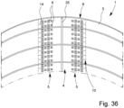
- Fig. 34 shows that the front sides 34 of the foil tunnel 33 are configured to be at least partially closed.
- the sheet 1 and/or the basic film 3 extends to the floor.
- a spacing is provided with production of a ventilation area between the end of the basic film 3 and the floor.
- the covered area can be seen, for example, in Fig. 36 .
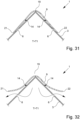
- Figs. 31 and 32 show different states that the sheet 1 can have.
- the material and/or the nature and/or quality of the cover film 9 is selected in such a way that the states shown in Figs. 31 and 32 can be realized and/or obtained.
- the first state is characterized by the fact that the temperature T in the covered area and/or the temperature T of the greenhouse climate is below a transition temperature T 1 .
- the transition temperature T 1 can variate depending on different uses, in particular depending on different cultivated plants.
- the temperature T 1 also depends on the outdoor temperature T 0 .
- the outside temperature T 0 is determined outside the covered area, in particular outside the greenhouse and/or the foil tunnel 33.
- the temperature T 1 and also the temperature T of the greenhouse climate can be configured larger than the temperature T 0 due to the greenhouse effect achieved by covering with the sheet 1. In this context, it is understood that the temperature T of the greenhouse climate (to determine the difference to the transition temperature T 1 ) is determined in the covered area.
- the temperature T of the greenhouse climate is to be determined in the central area 4 of the sheet 1 in relation to the longitudinal direction L, in particular with a maximum deviation of +/-30% of the length of the sheet 1 starting from the center. Also, the temperature T of the greenhouse climate is determined in the roof area of the covered area, in particular with a maximum distance of less than 1 m to the underside of the sheet 1 facing the cultivated plants 2.
- the underside of the cover film 9 lies flat against and/or on the upper side of the basic film 3 at least substantially in the area of the free spaces 11.
- the cover film 9 covers and/or closes at least 60%, more preferably at least 80%, and in particular all ventilation openings 6.
- Fig. 32 shows a second state of the sheet 1 shown in Fig. 31 .
- This second state can be realized due to the material and/or the nature and/or quality of the cover film 9, in particular in relation to the basic film 3.
- the second state shown in Fig. 32 results in particular at a temperature T in the covered area which is greater than the transition temperature T 1 .
- T the transition temperature
- the cover film 9 lifts off and/or has already lifted off in certain areas relative to the upper side of the basic film 3 with the production of free spaces 11. This allows the heated air to escape from the covered area via the ventilation openings 6, as shown schematically in Fig. 32 .
- the transition between the first and the second state results in particular from convection of the heated air in the covered area.
- the first and the second state can also have due to external weather conditions, for example due to heavy rain and/or by wind and/or in case of wet surfaces, in particular due to adhesion effects. It is understood, however, that a change of states as a function of the transition temperature T 1 can result due to the material and/or the nature and/or the quality of the cover foil 9 and in particular without the need for external further influencing weather conditions, such as wind and/or rain.
- the cover film 9 is in (in particular full-surface) contact with the upper side of the basic film 3 up to the transition temperature T 1 , wherein at a temperature T in the covered area above the transition temperature T 1 , the cover film 9 lifts off or has already lifted off at least in part relative to the upper side of the basic film 3 with production and/or forming of free spaces 11.
- the cover film and/or the material of the cover film 9 is configured to be more elastic and/or softer and/or less rigid than the basic film 3 and/or the material of the basic film 3.
- the cover film 9 comprises a lower weight per unit area and/or grammage than the basic film 3. It is understood that the aforementioned material properties of the cover film 9 can be used in particular to ensure the change of state as shown schematically in Figs. 31 and 32 .
- a self-regulating system of the greenhouse climate can be ensured by a possible change of the ventilation behavior in the covered area adapted to the transition temperature T 1 .
- Figs. 34 and 35 also show the two different states that are realized, in particular, when the temperature T in the covered area exceeds T 1 .
- Fig. 34 shows a second state in which the temperature T in the covered area is above the transition temperature T 1
- Fig. 35 shows the first state in which the cover film 9 covers the ventilation openings 6 and the temperature T in the covered area is below the transition temperature T 1 .
- the cover film 9 shown in Fig. 31 and the basic film 3 shown in Fig. 31 may comprise polyethylene, in particular low-density polyethylene (LDPE), as the material. In further embodiments, it may also be provided that the cover film 9 and/or the basic film 3 are made of polyethylene.
- LDPE low-density polyethylene
- the cover film 9 changes from the first state to the second state - that is, it starts to lift off.
- cover film 9 shown in Fig. 31 , it is provided that it comprises a different material than the basic film 3. In further embodiments, however, it can also be provided that both the cover film 9 and the basic film 3 are composed of the same material. Then, the nature and/or the quality of the cover film 9 can be adapted such that in particular the two previously discussed states of the sheet 1 can be realized and/or obtained.
- cover film 9 and/or the basic film 3 comprise an additional material of plastic and/or a polymer, in particular ethylene-vinyl acetate copolymer (EVA), linear low density polyethylene (LLDPE), high density polyethylene (HDPE) and/or medium density polyethylene (MDPE) and/or mixtures thereof.
- EVA ethylene-vinyl acetate copolymer
- LLDPE linear low density polyethylene
- HDPE high density polyethylene
- MDPE medium density polyethylene
- cover film 9 shown in the embodiments illustrated and the basic film 3 are each configured as a single layer. In further embodiments not shown in more detail, however, it is also possible to provide for a multilayer structure of the basic film 3.
- the layered structure of the aforementioned films 3, 9 can be selected in particular as a function of the desired transition temperature T 1 of the greenhouse climate.
- the nature and/or the quality, in particular the texture and/or the layer structure, of the basic film 3 can differ from the cover film 9.
- the cover film 9 can comprise a lower layer thickness than the basic film 3.
- the lower layer thickness can ensure that the cover film 9 can be lifted off in the second state, as shown in Figs. 34 and 32 , respectively.
- cover film 9 may be configured as a monoaxial or biaxial stretched film web and/or film sheet.
- the basic film 3 is configured from the same material as the cover film 9, and in particular has only been unstretched relative to the cover film 9.
- cover film 9 can comprise an embossing.
- the embossed cover film 9 can thus comprise such a quality that it is possible to apply and reapply the cover film 9 to the ventilation openings 6 when the transition temperature T 1 in the covered area is exceeded and/or undershot.
- cover film 9 may comprise as material and/or consist of very low density polyethylene (VLDPE), ultra low density polyethylene (ULDPE), a plastomeric material and/or mixtures thereof.
- VLDPE very low density polyethylene
- ULDPE ultra low density polyethylene
- plastomeric material a material and/or mixtures thereof.
- the aforementioned materials may in particular provide a less rigid cover film 9 relative to the basic film 3.
- the basic film 3 may comprise a width between 0.5 to 40 m, more preferably between 1 to 20 m, more preferably between 1.5 to 15 m.
- the cover film 9 may comprise a width less than the basic film 3, wherein the width of the cover film 9 may in particular be greater than 50 cm, more preferably between 100 to 150 cm.
- the length of the sheet 1 may vary depending on the different states of use.
- the sheet 1 may be provided as a roll product to a customer or a user.
- the sheet 1 may comprise a length of at least 1 m, more preferably between 10 to 800 m.
- the distance between two weldings 14 and/or connection areas 10 directly in proximity in longitudinal sheet direction L can be at least 5 cm, in particular between 25 to 60 cm, as shown in Fig. 1 .
- the length (in particular in longitudinal sheet direction L) of the free space 11 can be at least 5 cm, in particular between 25 to 60 cm.
- the cover film 9 can comprise a layer thickness of at least 50 ⁇ m, in particular between 150 to 200 ⁇ m.
- the weight per unit area of the cover film 9 can be at least 20 g/m 2 and in particular between 110 to 180 g/m 2 .
- the basic film 3 can comprise a layer thickness of at least 70 ⁇ m, preferably between 80 to 350 ⁇ m, more preferably between 200 to 300 ⁇ m.
- the basic film 3 can comprise a basis weight and/or grammage of at least 50 g/m 2 and in particular between 200 to 250 g/m 2 .
- the transition temperature T 1 and thus the selection of a particular cover film may also vary depending on different cultivation plants 2. According to the invention the transition temperature T 1 is greater than 20 °C. Preferably, the transition temperature T 1 is greater than 30 °C, more preferably between 30 to 50 °C and in particular at 38 °C +/- 5 °C. The transition temperature T 1 is ultimately reached as a function of the outside temperature T 0 provided outside the covered area.
- the ventilation openings 6 shown in Fig. 1 can comprise a maximum diameter of at least 3 mm.
- the maximum diameter of the ventilation openings 6 and/or at least one ventilation opening 6 can preferably be between 50 and 100 mm.
- Figs. 1 to 30 show various embodiments of the sheet 1 according to the invention.
- the features and/or aspects described below in connection with Figs. 1 to 30 can apply to the sheet 1 configured according to the invention - but need not apply.
- Fig. 1 shows an elongated sheet 1 for covering cultivated plants 2.
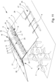
- the covering of cultivated plants 2 by the sheet 1 is shown in a schematic illustration in Fig. 11 .
- the sheet 1 comprises a basic film 3 made of plastic.
- a ventilation area 5 extending in the longitudinal sheet direction L with a plurality of ventilation openings 6.
- the central area 4 of the basic film 3 is especially arranged at least essentially in the area of the centre line of the basic film 3.
- the centre line runs parallel to the longitudinal edges 7, 8 of the basic film 3.
- the central area 4 can also be at a distance from the centre line and/or is not designed to be mirror-symmetrical in relation to the centre line. In any case, the central area 4 is at a distance from both longitudinal edges 7, 8 of the basic film 3.
- the distance to the respective longitudinal edges 7, 8 can be different. Especially the distances starting from the respective longitudinal edge of the central area 4 to the respective immediately neighbouring longitudinal edge 7, 8 differ in further embodiments by a maximum of 50 %, preferably a maximum of 20 %.
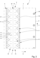
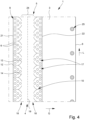
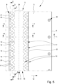
- Fig. 4 shows that a plastic cover film 9 is provided on the ventilation area 5, running in the longitudinal sheet direction L of the basic film 3, and is firmly welded to the basic film 3 over a plurality of connection areas 10 consecutive in the longitudinal sheet direction L.
- Fig. 1 does not show that the cover film 9 is connected to the basic film 3 by the connection areas 10 in such a way that free spaces 11 are formed.
- the free spaces 11 are shown schematically in Fig. 11 .
- the free spaces 11 are shown in Fig. 6 , 8 and 10 .
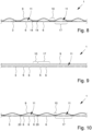
- Figs. 6 to 10 are schematic sectional views of sheet 1 shown in Fig. 5 in its (actual) state of use. Sheet 1 is thereby used as a gable roof, as can be seen schematically in Fig. 11 .
- Fig. 6 shows cut A-A from Fig. 5 , but in the state of use of the sheet 1 shown in Fig. 5 .
- Fig. 7 shows the cut along line B-B.
- Fig. 6 is a schematic illustration of free space 11. In Fig. 7 no free space 11 is available. This is finally due to the fact that the cut B-B runs through the connection areas 10.
- Fig. 8 shows the cut C-C from Fig. 5 .
- the sheet 1 is shown in an elongated state, so that the free spaces 11 are shown schematically.
- Fig. 9 shows the cut D-D from Fig. 5 , wherein the free space 11 is at least essentially continuous.
- connection area 10 is designed to be inclined at least in some areas with respect to a weld start point 12 and a weld end point 13 with respect to the cross direction Q running orthogonally to the longitudinal sheet direction L.
- the weld start point 12 and/or the weld end point 13 thereby adjoin the immediately neighbouring free space 11. Otherwise, weld points 12, 13 may represent the starting point or end point of a weld line and/or section - but need not.
- An inclined design between weld start point 12 and weld end point 13 is to be understood as meaning that the line connecting the weld start point 12 with the weld end point 13, especially an imaginary line, is inclined and/or angled to the cross direction Q.
- straight connection areas 10 are possible, in particular having straight weldings 14, preferably with respect the cross direction Q running orthogonally to the longitudinal sheet direction L.
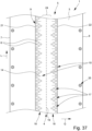
- Fig. 37 shows that the connected area 10 is designed in such a way that the weldings 14 are straight, in particular at least substantially parallel with regard to the cross direction Q and in particular are arranged parallel to each other.
- Figs. 25 to 29 show differently shaped connection areas 10.
- the "imaginary" line connecting the weld start point 12 with the weld end point 13 is shown as a dashed line. It is also clear that different weld points can form the weld start point 12 and the weld end point 13. Welding points 12, 13 are preferably the outermost points of a weld line.
- Fig. 25 shows that weld start point 12 and weld end point 13 are located on different weld lines 15, 16.
- connection area 10 may also include further weld spots or sections where the line connecting these weld spots or sections does not comprise an arrangement inclined to the cross direction Q.
- Fig. 2 shows that the weld start point 12 is the outermost weld point of the connection area 10 and faces the longitudinal edge 7.
- Fig. 2 further shows that the weld end point 13 is the outermost weld point of a connection area 10.
- this design does not necessarily have to be implemented.
- the weld end point 13 is in any case further away from the longitudinal edge 7 than the weld start point 12.
- weld start point 12 does not have to be the outermost weld point of a connection area 10, but it can be.
- the weld end point 13 can face the further longitudinal edge 8 of the basic film 3 opposite the longitudinal edge 7. Finally, the weld end point 13 is closer to the further longitudinal edge 8 than the weld start point 12.
- the inclined arrangement between weld start point 12 and weld end point 13 can be used to ensure that the enclosed free space 11 tapers - especially towards separating line 19 of the sheet 1. In other words, this means that the free space 11 increases and/or widens towards the neighbouring longitudinal edge starting from separating line 19.
- a schematic illustration in perspective of the narrowing and/or expansion of the free space 11 can be seen especially in Fig. 11 .
- Fig. 1 shows that the line connecting the weld start point 12 with the weld end point 13 encloses an angle to the cross direction Q of at least 5°, preferably between 30° and 50°.
- the above-mentioned angle may also depend on the fact which weld points of the connection area 10 are identified as weld start point 12 and weld end point 13.
- Fig. 2 shows that different weld points can be identified as weld start point 12 and weld end point 13.
- the outermost weld points of connection area 10 are finally weld start point 12 and weld end point 13. This is not necessarily the case, however.
- the above-mentioned angle depends on it, which is especially at least 5° in any case.
- connection area 10 especially all connection areas 10
- at least one welding 14 which is oblique, especially continuous, in relation to the cross direction Q running orthogonally to the longitudinal sheet direction L.
- at least two weldings 14 are provided for each connection area 10.
- the weld start point 12 and the weld end point 13 can especially be located on the welding 14. This is shown schematically in Fig. 1 and Figs. 3 to 5 .
- the welding 14 can be designed straight as shown in Fig. 1 and Fig. 3 or curved as shown in Fig. 4 . In the case of a curved design of the welding 14, it is especially intended that the welding 14 is designed at least essentially in the form of a curved section.
- Fig. 2 shows a further embodiment in which no continuous welding 14 is realized. It is thereby provided that the weld start point 12 is arranged on a first welding line 15 and the weld end point 13 on a further welding line 16.
- the further welding line 16 is not only at a distance from the first welding line 15 in the illustrative example shown in Fig. 2 , but is arranged offset and/or shifted to it - especially in relation to the longitudinal sheet direction L.
- Fig. 2 shows that both the first and the further welding lines 15, 16 run at least essentially in cross direction Q of the sheet 1.
- Fig. 1 shows that the cover film 9 extends continuously in the longitudinal sheet direction L and over the entire length of the basic film 3.
- the cover film 9 is designed to be continuous, but does not extend over the entire length of the basic film 3 in the longitudinal sheet direction L.
- the basic film may comprise 3 areas which do not include ventilation area 5. These areas do not have to be covered by the cover film 9 - but they can be covered in other embodiments.
- cover film 9 can comprise individual sections which can especially attach one another and/or overlap one another. These individual sections of the cover film 9 can also be connected to the basic film 3 via connection areas 10.
- Ventilation area 5 comprises a plurality of ventilation sections 17.
- the ventilation sections 17 are adjacent to each other and arranged one behind the other in the longitudinal sheet direction L.
- a ventilation section 17 may in particular contain a grouped arrangement of ventilation openings 6.
- a ventilation section 17 may include at least one ventilation opening 6. It is more preferably that all ventilation openings 6 and/or at least substantially all ventilation openings 6 are arranged in ventilation sections 17. In any case, at least 80 % of the ventilation openings 6 are arranged in ventilation sections 17.
- Fig. 1 shows that in each case and/or at least one connection area 10 is arranged between neighbouring ventilation sections 17.
- neighbouring ventilation sections 17 are separated from each other by connection areas 10.
- each connection area 10 can comprise the weld start point 12 and the weld end point 13.
- the connection areas 10 as well as the ventilation sections 17 can be designed at least essentially identically or can differ from each other.
- connection areas 10 and ventilation sections 17 are provided, running in the longitudinal sheet direction L.
- Figs. 1 and 3 show that the weldings 14 are designed to be inclined and/or sloping towards the immediately neighbouring ventilation section 17.
- two weldings 14 are provided in one connection area 10. Thereby the welding 14 inclined towards the directly neighbouring and/or adjacent ventilation section 17 is closer to the ventilation section 17 in question than the other welding 14 of the same connection area 10.
- the line connecting the weld start point 12 with the weld end point 13 is designed to be inclined and/or oblique towards the immediately neighbouring ventilation section 17.
- at least two lines can be formed by at least two weld end points 13, which, however, particularly refer to the same weld start point 12.
- Fig. 11 shows that the free spaces 11 are each provided above a ventilation section 17 and the connection areas 10 are designed in such a way that the respective free space 11 tapers towards a longitudinal edge 7, 8 of the sheet.
- the free space 11 tapers especially towards the side facing away from the opening of the free space 11 and/or the longitudinal edge 7, 8 facing away from the opening of the free space 11.
- the ventilation can take place via the opening of the free space 11.
- the free space 11 can especially be formed over a ventilation section 17 in such a way that the length of the basic film 3 running in the longitudinal sheet direction L is smaller than the length of the cover film 9 running in the longitudinal sheet direction L.
- the length of the cover film 9 can refer to the "pulled out” state.
- the greater length of the cover film 9 compared to the basic film 3 results in a curvature of the cover film 9 over the ventilation section 17.
- the difference in length between the basic film 3 and the cover film 9 thus creates the free space 11 between the basic film 3 and the cover film 9.
- the cover film 9 is designed in its original state, not yet bonded to the basic film 3, to be at least 20% longer than the length of the covered area of the basic film 3.
- Fig. 1 shows that the ventilation area 5 comprises two ventilation segments 18 which are opposite each other at least in some areas.
- the ventilation segments 18 can especially each comprise a plurality of ventilation sections 17.
- the ventilation segments 18 are designed mirror-symmetrically to a mirror axis running parallel to the longitudinal sheet direction L. In other designs, the mirror symmetry axis can also be formed by further axes.
- one ventilation segment 18 forms a side surface of the gable roof.
- the ventilation segments 18 are finally separated from each other by a separating line 19.
- the separating line 19 can be the centre line of the basic film 3 and/or the sheet 1. In other embodiments it may also be provided that the separating line 19 is defined by the axis resulting from the support of sheet 1 on a rope, bar or the like. For example, the separating line 19 can be defined by an axis of support.
- the separating line 19 need not be a physical line, fold or the like, it can be an imaginary axis.
- the separating line 19 can also be the axis of symmetry for the mirror-symmetrical design of the ventilation segments 18.
- the separating line 19 can coincide with the centre line of the basic film 3 - but does not have to.
- both ventilation segments 18 are arranged in the central area 4 of the basic film 3.
- the welding 14 or the welding lines 15, 16 can comprise different lengths as a function of the intended use.
- the welding 14 and/or the first and/or further welding lines 15, 16 extend over at least 10%, especially between 30 % and 80 %, of the width of a ventilation section 17 running in cross direction Q and/or the width of the ventilation area 5 and/or the width of the ventilation segment 18.
- the widths of the above-mentioned areas refer especially to the width extending at least substantially in the cross direction Q.
- the welding 14 and/or the first and/or further welding lines 15, 16 comprise a length of at least 10 %, especially between 30 % and 80 %, of the width of a ventilation section 17 and/or width of the ventilation area 5 and/or width of the ventilation segment 18.
- the length of welding 14 and/or of weld lines 15, 16 may refer to the total length which can be determined independently of the longitudinal sheet direction L and/or cross direction Q.
- welding 14 and/or the first and/or further welding lines 15, 16 are designed to be interrupted.
- Fig. 1 shows that immediately neighbouring weldings 14 design a V-shape, at least in some areas. Thereby the respective legs of the V-shape, which are designed by the respective welding 14, can pass directly into each other to form a pointed corner of the V-shape or be spaced from each other. In the illustrative example shown in Fig. 1 , it is intended that the pointed corner of the V-shape is designed.
- a V-shape is designed between immediately neighbouring weldings 14 of a connection area 10 - as shown schematically in Figs. 4 and 5 .
- connection area 10 includes a further welding 20 next to welding 14 or next to the first and/or further welding lines 15, 16.
- the further welding 20 can be at least essentially aligned in cross direction Q, as shown in Fig. 1 and Figs. 3 to 5 .
- the further welding 20 can merge into the weldings 14 of the connection area 10 or be at a distance from them.
- a V-shaped arrangement of neighbouring weldings 14 can especially enable a Y-shaped design of the connection area 10.
- a Y-shaped design is also understood to be one in which the further welding 20 is at a distance from the weldings 14, as shown in Figs. 1 and 5 .
- Figs. 1 and 3 to 5 show a Y-shaped design of the connection area 10, in which a further welding 20 interacts with the V-shape formed by the weldings 14.
- the further welding 20 can be inclined or straight and/or at least substantially parallel with respect to the cross direction Q. Alternatively or additionally, the further welding 20 can also be curved - at least partially.
- Figs. 1 and 2 show that the weld end point 13 can face the separating line 19.
- the weld start point 12 can especially face away from the separating line 19 and be arranged closer to a further longitudinal edge 8 of the basic film 3 and/or a longitudinal edge 22 of the cover film 9.
- the longitudinal edge 22 of the cover film 9 can especially be turned towards the further longitudinal edge 8 of the basic film 3.
- the free space 11 can be tapered towards the separating line 19.
- the weldings 14 can also be arranged especially in the upper area of the respective ventilation segments 18 facing the separating line 19. Alternatively or additionally, it may be provided that the further welding 20 is arranged in the lower area of the ventilation segments 18 facing away from the separating line 19.
- connection areas 10 of the respective ventilation segments 18 are designed to be at least essentially mirror-symmetrical.
- the separating line 19 and/or the centre line of the basic film 3 can be the mirror axis.
- the mirror axis runs at least essentially parallel to the longitudinal sheet direction L - at least in other embodiments.
- the further welding 20 can be designed to be straight or curved as a whole or in certain areas.
- the further welding 20 is designed to be at least essentially straight and in cross direction Q.
- connection area 10 comprises an intermediate ventilation channel 23.
- the intermediate ventilation channel 23 can especially be formed by a distance between the weldings 14 and the further welding 20.
- the intermediate ventilation channel is finally formed by the spacing between the first and further welding lines 15, 16.
- the further welding 20 can be provided in other embodiments in such a way that it extends over at least 5 % of the width of a ventilation section 17 and/or the width of a ventilation area 5 and/or the width of a ventilation segments 18.
- the length, which can be independent of the longitudinal sheet direction L and/or the cross direction Q, of the further welding 20 corresponds to at least 5 %, especially between 10 % and 50 %, of the width of a ventilation section 17 and/or the width of a ventilation area 5 and/or the width of a ventilation segments 18.
- the width of the cover film 9 should be smaller than the width of the basic film 3.
- the cover film 9 overlaps the ventilation area 5, especially on both sides, and especially serves to cover the ventilation openings 6.
- the width of the cover film 9, which extends particularly in the cross direction Q, corresponds to a maximum of 50 %, especially a maximum of 30 %, of the width of the basic film 3.
- Fig. 11 shows in a schematic illustration that the cover film 9 lies on the basic film 3 in the area of a connection area 10, at least in some areas. Especially in the area of the connection area 10, the cover film 9 lies at least essentially tight and/or flat on the basic film 3. Preferably, the cover film 9 can also rest on the basic film 3 between the directly neighbouring weldings 14 of the respective connection area 10.
- Fig. 3 shows that a central transition area 24 covered by the cover film 9 is provided between the ventilation segments 18.
- This transition area 24 can be designed free of welding(s) or welding sections and/or free of ventilation openings 6.
- Fig. 11 shows that this transition area 24 can be used to rest on a tension cable or bar of a frame.
- An air exchange between the opposite ventilation sections 17 of the respective ventilation segments 18 can (but does not have to) be made possible via the transition area 14 in other embodiments.
- a ventilation section 17 comprises a plurality of ventilation openings 6.
- ventilation openings 6 are provided per ventilation section 17.
- the ventilation openings 6 can be arranged in rows.
- the number of ventilation openings 6 may be reduced in the successive rows of a ventilation section 17, especially towards separating line 19.
- the lowest row of the ventilation section 17 facing the nearest longitudinal edge 22 of the cover film 9 may comprise between 3 and 5 ventilation openings 6.
- the topmost row of ventilation section 17 facing away from the longitudinal edge 22 may have 1 to 2 ventilation openings 6.
- Fig. 3 shows that the area of the ventilation section 17 belonging to the basic film 3, and/or the area it occupies between neighbouring connection areas 10, preferably on both sides, tapers towards separating line 19. This taper is also further illustrated by the decreasing number of ventilation openings 6 in the rows.
- ventilation openings 6 can be designed as breakthroughs of the basic film 3.
- Fig. 11 shows that the basic film 3 can comprise fastening means 25 on its longitudinal edges 7, 8.
- the fastening means 25 are formed by an opening 26 in the basic film 3 and by a hook 27 engaging in the opening 26.
- the hooks 27 can be fastened, for example, to a frame or to the support means 28.
- Such a support means 28 is also shown in a schematic illustration in Fig. 11 .
- the support means 28 can be connected to the floor and/or supported by it.
- neighbouring sheets 1 can also be connected to each other via fastening means 25 and preferably connected directly to each other - for example via hooks 27.
- hooks for example, a tension belt or a tension cable is also possible.
- the basic film 3 and/or the cover film 9 is/are designed to be at least partially, preferably completely, translucent and/or transparent.
- Light transmission is especially intended for visible light and/or daylight, preferably in a wavelength range between 400 nm and 700 nm.
- thermoplastic material can be provided as the material for the cover film 9 and/or the basic film 3.
- the cover film 9 and/or the basic film 3 can be made of the thermoplastic material.
- the thermoplastic material can be a polyolefinic material, preferably polyethylene, soft polyethylene, linear low density polyethylene, ethylene-butyl-acrylate copolymer, ethylene-vinyl acetate and/or mixtures thereof.
- the basic film 3 comprises a width of between 0.5 m and 40 m, especially between 1.5 m and 15 m.
- the width of the basic film 3 can be varied as a function of the intended use, for example for greenhouses or for covering vines and/or soft fruit.
- the cover film 9 can comprise a width of at least 10 cm, especially between 0.4 m and 1.0 m.
- the sheet 1 can be supplied rolled up and comprise a length of between 10 m and 800 m.
- the basic film 3 and/or the cover film 9 is/are designed to be breathable.
- the cover film may comprise 9 micro-perforations, which may lead to a better air circulation, especially to an improved ventilation of the covered area.
- heat-absorbing additives can be added to the material of the cover film 9. This also improves the air circulation.
- Fig. 11 schematically shows the use of a sheet 1 according to one of the embodiments described earlier in the agricultural sector.
- the sheet 1 is preferably used to cover cultivated plants 2, as shown in Fig. 11 .
- the use of the sheet 1 is especially for protection against rain and/or weather and/or for ventilation of the covered area.
- Fig. 30 shows, that the sheet 1 can be used in greenhouses, preferably as external cover.
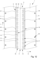
- Fig. 12 shows an elongated sheet 1 for covering cultivated plants 2 with a basic film 3 made of plastic.
- the ventilation area 5 In the central area 4 of the basic film 3 there is a ventilation area 5 extending in the longitudinal sheet direction L, which can be used to ventilate the covered area when the sheet 1 is in use.
- the ventilation area 5 comprises a plurality of ventilation openings 6.
- Fig. 12 also shows that two opposite corners 29, 30 of at least one ventilation opening 7 are provided in the cross direction Q of sheet 1, which runs at least substantially orthogonally to the longitudinal sheet direction L.
- the at least one ventilation opening 7 may comprise further corners. Directly opposite further corners may, for example, be arranged at least substantially in the longitudinal sheet direction L, as shown in Fig. 12 .
- the opposite corners 29, 30 are especially arranged in such a way that the line connecting the opposite corners 29, 30 runs at least essentially in cross direction Q.
- the line connecting the corners 29, 30 can also be designed to be (slightly) inclined in relation to the cross direction Q and, in particular, can form a first angle to the cross direction of maximum +/- 45°, even more preferably maximum +/- 30° and especially maximum +/- 10°.
- the first angle is between the line connecting the opposite corners 29, 30 and the cross direction Q and refers especially to the smaller angle included.
- the corners 29, 30 can especially be arranged in such a way that the ventilation opening 6 does not comprise any further corner or any further section or area which protrudes opposite the respective corner 29, 30 - in relation to the respective immediately neighbouring longitudinal edge 7, 8 of the basic film 3. Especially no further corner or further section/area of the ventilation opening 6 is closer to the respective immediately adjacent longitudinal edge 7, 8 of the basic film 3.
- Such an overhang would in particular mean that if the sheet 1 is pulled in the cross direction Q with a tensile force, this overhanging area would first hit a tension cable or bar of a frame, for example.
- sheet 1 is pulled in the state of use, especially in the cross direction Q, onto a tension cable, bar or the like.
- the tensile force thereby acts mostly at least essentially in the cross direction Q.
- the corners 29, 30 can form the outermost boundary points of the ventilation opening 6 in relation to the respective immediately neighbouring longitudinal edge 7, 8 of the basic film 3.
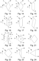
- Figs. 13 to 24 show different embodiments of possible forms of the ventilation opening 6 apart from the circular form which is shown in several embodiments. Each of the forms may be used in each shown and claimed embodiment, respectively - alone or in combination with one or more other forms.
- the cross direction Q is (schematically) drawn in. This serves as a schematic illustration of the orientation of the ventilation opening 6 on/in the basic film 3.
- the corners 29, 30 form the outermost boundary points to the respective adjacent longitudinal edge 7, 8 of the basic film 3 and/or no further section/area and/or no further corner 31 is aligned with the respective corner 29, 30, is at the same height in relation to the cross direction Q or protrudes beyond it, especially in relation to the respective immediately adjacent longitudinal edge 7, 8 of the basic film 3.
- Fig. 13 shows that the opposite corners 29, 30 are designed to be at least essentially pointed and/or end in a point whose apex may also comprise a curve with a small radius.
- Fig. 21 shows schematically that the opposite corners 29, 30 can also be designed with a rounded edge.
- the design shown in Fig. 12 also provides that a plastic cover film 9 running in the longitudinal sheet direction L of the basic film 3 is applied to the ventilation area 5, forming free spaces 11 for air exchange, and is firmly welded to the basic film 3 over a plurality of connection areas 10 following one another in the longitudinal sheet direction L.
- the ventilation opening 6 comprises a design that is at least substantially elongated in the cross direction Q.
- An elongated design is especially understood to mean that the length running in the cross direction Q is greater than the width of the ventilation opening 6 running in the longitudinal sheet direction L.
- Fig. 13 shows that the ventilation opening 6 is designed as a rhombus.
- the ventilation opening may comprise 6 straight or curved outer borders, as shown schematically in Figs. 13 to 24 .
- Fig. 14 shows a ventilation opening 6 with opposite pointed corners 29, 30, wherein the outer borders connecting the corners 29, 30 are designed 32 curved.
- Fig. 15 and Fig. 16 each show a ventilation opening 6 designed as a hexagon, wherein the design shown in Fig. 15 has at least essentially straight outer boundary edges.
- the legs of the outer boundary immediately adjacent to the corners 29, 30 are designed to be at least essentially in the shape of sections of an arc.
- Figs. 17 and 18 each also show a ventilation opening 6 designed as a hexagon, which especially is neither symmetrical nor rotationally symmetrical.
- the ventilation opening 6 is designed to be mirror-symmetrical at least to at least one mirror axis.
- Ventilation opening 6 may be designed to be rotationally symmetrical.
- Figs. 19 and 20 show ventilation openings 6 of different widths.
- Fig. 23 shows an isosceles, obtuse triangle-shaped ventilation opening 6.
- Fig. 24 shows a ventilation opening 6 in the form of an equilateral triangle.
- opposite corners 29, 30 are arranged not offset to each other in relation to the cross direction Q.
- a staggered and/or shifted arrangement as schematic illustration in Fig. 17 , can also be provided in principle.
- Fig. 19 shows schematically that the ventilation opening 6 comprises only the opposite corners 29, 30 as outer corners at an angle ⁇ starting from the line connecting the opposite corners 29, 30 of at least +/- 45°, preferably of at least +/- 80°.
- the centre point M of the ventilation opening 6 thereby serves as the starting point for the above-mentioned determination of the angle.
- the ventilation opening 6 comprises a maximum length of at least 1 mm, especially between 4 mm and 80 mm.
- the length of the ventilation opening 6 is aligned in the cross direction Q, especially in the state of use.
- the ventilation opening 6 can comprise a maximum width of at least 0.5 mm.
- the ventilation opening 6 comprises an area of at least 0.01 cm 2 , especially between 1 cm 2 and preferably 3 cm 2 .
- the opposite corners 29, 30 shown in the afore-mentioned illustrative examples each comprise an angle of at least 10°. Especially this angle is between 30° and 90°.
- an elongated sheet 1 is provided for covering cultivated plants 2.
- the elongated sheet 1 comprises a basic film 3 made of plastic. Especially the sheet 1 is designed according to one of the previous designs.
- a ventilation area 5 extending in the longitudinal sheet direction L is provided with a plurality of ventilation openings 6.
- a plastic cover film 9, extending in the longitudinal sheet direction L of the basic film 3, is applied on the ventilation area 5 in such a way that free spaces 11 for air exchange are formed.
- the cover film 9 is firmly welded to the basic film 3 over a plurality of connection areas 10 consecutive in the longitudinal sheet direction L.
- the sum of the areas of all ventilation openings 6 is at least 1%, especially between 1.1% and 3%, of the total area of the basic film 3.
Landscapes
- Life Sciences & Earth Sciences (AREA)
- Environmental Sciences (AREA)
- Health & Medical Sciences (AREA)
- General Health & Medical Sciences (AREA)
- Toxicology (AREA)
- Chemical & Material Sciences (AREA)
- Engineering & Computer Science (AREA)
- Materials Engineering (AREA)
- Soil Sciences (AREA)
- Protection Of Plants (AREA)
- Laminated Bodies (AREA)
Claims (14)
- Feuille allongée (1) pour couvrir les cultures agricoles (2) afin de créer un climat de serre dans la zone couverte, avec un film de base allongé (3) en plastique,dans laquelle dans une zone de ventilation (5) s'étendant dans la direction longitudinale de la feuille (L) et comportant de plusieurs ouvertures de ventilation (6) est prévue la zone centrale (4) du film de base (3),dans laquelle un film de couverture (9) en matière plastique s'étendant dans la direction de la feuille longitudinal (L) du film de base (3) est appliqué sur la zone de ventilation (5) formant des espaces libres (11) pour l'échange d'air et est solidement soudé au film de base (3) par une pluralité de zones de connexion (10) se succédant dans la direction de la feuille longitudinal (L),dans laquelle le film de couverture (9) est constitué d'une seule couche,caractérisée en ce quele matériau et/ou la qualité du film de couverture (9) sont sélectionnés de cette manière,que le film de couverture (9), dans un premier état, repose à plat contre et/ou sur la face supérieure du film de base (3) au moins essentiellement dans la zone des espaces libres (11) et, de préférence par convection de l'air chauffé dans la zone couverte, dans un deuxième état se soulève au moins partiellement par rapport à la face supérieure du film de base (3) formant des espaces libres (11), dans laquelle le premier état est maintenu jusqu'à une température de transition T1 du climat de serre et dans laquelle le deuxième état est obtenu et/ou réalisé à partir de la température de transition T1 du climat de serre,dans laquelle la température de transition T1 est supérieure à 20 °C, de préférence supérieure à 30 °C, plus préférentiellement comprise entre 30 et 50 °C et en particulier à 38 °C +/- 5 °C,en ce que le film de couverture (9) et le matériau du film de couverture (9) sont configurés pour être plus élastiques, plus souples et moins rigides que le film de base (3) et le matériau du film de base (3) eten ce que le film de couverture (9) a un grammage inférieur à celui du film de base (3).
- Feuille selon la revendication 1, caractérisée en ce que le film de couverture (9) et/ou le film de base (3) comprend comme matériau du polyéthylène, en particulier du polyéthylène basse densité (LDPE), et/ou est constitué de celui-ci.
- Feuille selon l'une des revendications précédentes, caractérisée en ce que le film de couverture (9) comprend un matériau différent de celui du film de base (3).
- Feuille selon l'une des revendications précédentes, caractérisée en ce que le film de couverture (9) et/ou le film de base (3) comportent un matériau additif en matière plastique et/ou en polymère, en particulier en copolymère d'éthylène-acétate de vinyle (EVA), en polyéthylène linéaire de faible densité (LLDPE), en polyéthylène de haute densité (HDPE) et/ou en polyéthylène de moyenne densité (MDPE).
- Feuille selon l'une des revendications, caractérisée en ce que le film de base (3) est configuré en une seule couche, et/ou
en ce que la qualité, en particulier la texture et/ou la structure de la couche, du film de base (3) diffère de celle du film de couverture (9), en particulier dans laquelle le film de couverture (9) comprend une épaisseur de couche inférieure à celle du film de base (3). - Feuille selon l'une des revendications précédentes, caractérisée en ce que le film de couverture (9) est configuré comme une feuille étirée monoaxiale ou biaxiale et/ouen ce que le film de couverture (9) comprend un gaufrage et/ouen ce que le film de couverture (9) comprend comme matériau et/ou est constitué de polyéthylène à très basse densité (VLDPE), de polyéthylène ultra basse densité (ULDPE), d'un matériau plastomère et/ou de leurs mélanges.
- Feuille selon l'une des revendications, caractérisée en ce que le film de base (3) comprend une largeur comprise entre 0,5 et 40 m, de préférence entre 1 et 20 m, de préférence entre 1,5 et 15 m, et/ou en ce que le film de couverture (9) comprend une largeur d'au moins 10 cm, de préférence entre 10 cm et 2 m, plus préférentiellement supérieure à 50 cm, de préférence entre 100 cm et 150 cm, et/ou
en ce que la feuille (1) comprend une longueur d'au moins 1 m, de préférence entre 2 et 1000 m, plus préférentiellement entre 10 et 800 m. - Feuille selon l'une des revendications précédentes, caractérisée en ce que la distance entre deux soudures (14) et/ou zones de connexion (10) directement adjacentes dans la direction longitudinale de la feuille (L) est d'au moins 5 cm, de préférence d'au moins 20 cm, plus préférentiellement comprise entre 25 et 60 cm.
- Feuille selon l'une des revendications précédentes, caractérisée en ce que le film de couverture (9) comprend une épaisseur de couche d'au moins 50 µm, de préférence entre 60 et 300 µm, plus préférentiellement entre 150 et 200 µm, et/ou
en ce que le film de couverture (9) comprend un grammage d'au moins 20 g/m2, de préférence entre 50 et 500 g/m2, plus préférentiellement entre 110 et 180 g/m2. - Feuille selon l'une des revendications précédentes, caractérisée en ce que le film de base (3) comprend une épaisseur de couche d'au moins 70 µm, de préférence entre 80 et 350 µm, plus préférentiellement entre 200 et 300 µm, et/ou
en ce que le film de base (3) comprend un grammage d'au moins 50 g/m2, de préférence entre 100 et 800 g/m2, plus préférentiellement entre 200 et 250 g/m2. - Feuille selon l'une des revendications précédentes, caractérisée en ce qu'au moins une ouverture de ventilation (6) présente un diamètre maximal d'au moins 3 mm, de préférence d'au moins 30 mm, plus préférentiellement compris entre 50 et 100 mm.
- Feuille selon l'une des revendications précédentes, caractérisée en ce que la somme des surfaces de toutes les ouvertures de ventilation (6) correspond à au moins 1%, plus préférentiellement entre 1,1% et 3%, de la surface totale du film de base (3).
- Feuille selon l'une des revendications précédentes, caractérisée en ce que la zone de connexion (10) est conçue pour être droite ou inclinée, au moins dans certaines zones, par rapport à un point de départ de la soudure (12) et à un point d'arrivée de la soudure (13) par rapport à la direction transversale (Q) s'étendant orthogonalement à la direction longitudinale de la feuille (L).
- Feuille selon la revendication 13, caractérisée en ce que la ligne reliant le point de départ de la soudure (12) au point d'arrivée de la soudure (13) forme un angle avec la direction transversale (Q) d'au moins 5°, de préférence entre 5° et 70°, plus préférentiellement entre 30° et 50°, et/ou
en ce qu'au moins une zone de connexion (10) comprend au moins une soudure (14) qui s'étend obliquement, plus préférablement de façon continue, par rapport à la direction transversale (Q) s'étendant orthogonalement à la direction longitudinale de la feuille (L).
Priority Applications (9)
| Application Number | Priority Date | Filing Date | Title |
|---|---|---|---|
| HRP20240410TT HRP20240410T1 (hr) | 2020-11-27 | 2021-11-08 | Izduženi list za prekrivanje poljoprivrednih uzgajanih biljaka |
| RS20240318A RS65296B1 (sr) | 2020-11-27 | 2021-11-08 | Izdužena folija za pokrivanje poljoprivrednih gajenih biljaka |
| US17/860,510 US12317782B2 (en) | 2020-11-27 | 2022-07-08 | Elongated sheet for covering agricultural cultivated plants |
| AU2022204933A AU2022204933B2 (en) | 2020-11-27 | 2022-07-11 | Elongated sheet for covering agricultural cultivated plants |
| ZA2022/08165A ZA202208165B (en) | 2020-11-27 | 2022-07-21 | Elongated sheet for covering agricultural cultivated plants |
| CN202210945057.3A CN116076291A (zh) | 2020-11-27 | 2022-08-08 | 用于覆盖农业栽培植物的长型片材 |
| IL297019A IL297019B1 (en) | 2020-11-27 | 2022-10-02 | Elongated sheet for covering cultivated plants |
| MX2022013300A MX2022013300A (es) | 2020-11-27 | 2022-10-21 | Lamina alargada para cubrir plantas cultivadas agricolas. |
| PE2022002592A PE20231003A1 (es) | 2020-11-27 | 2022-11-07 | Lamina alargada para cubrir plantas cultivadas agricolas |
Applications Claiming Priority (2)
| Application Number | Priority Date | Filing Date | Title |
|---|---|---|---|
| EP20210289.3A EP4005366B1 (fr) | 2020-11-27 | 2020-11-27 | Feuille allongée pour recouvrir des plantes cultivées |
| EP20210283.6A EP4005367B1 (fr) | 2020-11-27 | 2020-11-27 | Feuille allongée pour recouvrir des plantes cultivées |
Publications (3)
| Publication Number | Publication Date |
|---|---|
| EP4005368A1 EP4005368A1 (fr) | 2022-06-01 |
| EP4005368C0 EP4005368C0 (fr) | 2023-12-27 |
| EP4005368B1 true EP4005368B1 (fr) | 2023-12-27 |
Family
ID=78592503
Family Applications (1)
| Application Number | Title | Priority Date | Filing Date |
|---|---|---|---|
| EP21206952.0A Active EP4005368B1 (fr) | 2020-11-27 | 2021-11-08 | Feuille allongée pour recouvrir des plantes agricoles cultivées |
Country Status (13)
| Country | Link |
|---|---|
| US (1) | US12317782B2 (fr) |
| EP (1) | EP4005368B1 (fr) |
| CN (1) | CN116076291A (fr) |
| AU (1) | AU2022204933B2 (fr) |
| ES (1) | ES2975165T3 (fr) |
| HR (1) | HRP20240410T1 (fr) |
| HU (1) | HUE065798T2 (fr) |
| IL (1) | IL297019B1 (fr) |
| MX (1) | MX2022013300A (fr) |
| PE (1) | PE20231003A1 (fr) |
| PL (1) | PL4005368T3 (fr) |
| RS (1) | RS65296B1 (fr) |
| ZA (1) | ZA202208165B (fr) |
Families Citing this family (3)
| Publication number | Priority date | Publication date | Assignee | Title |
|---|---|---|---|---|
| EP4573651A1 (fr) * | 2022-08-18 | 2025-06-25 | VOEN VÖHRINGER GMBH & Co. KG | Dispositif de recouvrement |
| EP4529759A1 (fr) * | 2023-09-29 | 2025-04-02 | Reyenvas, S.A. | Stratifié en plastique |
| KR20260047838A (ko) * | 2024-10-02 | 2026-04-09 | 부영산업 주식회사 | 과수 가림막 |
Family Cites Families (11)
| Publication number | Priority date | Publication date | Assignee | Title |
|---|---|---|---|---|
| US3276943A (en) * | 1960-08-20 | 1966-10-04 | Kawamura Yuzo | Plastic film for thermal insulation |
| US3698131A (en) * | 1971-03-31 | 1972-10-17 | Gates Rubber Co | Plant cover and method |
| US4005547A (en) * | 1975-08-07 | 1977-02-01 | Caldwell Edward N | Thermally responsive ventilated cold frame |
| EP0017497A1 (fr) * | 1979-04-07 | 1980-10-15 | Bonas Brothers Limited | Abri horticole et procédé pour sa fabrication |
| US4387533A (en) * | 1980-08-01 | 1983-06-14 | Green George H | Method and apparatus for retaining heat in greenhouse and similar structures |
| EP0448714B1 (fr) * | 1989-10-18 | 1996-07-03 | Toray Industries, Inc. | Procede de production d'un tissu presentant des bandes lisses recouvrantes |
| GR1004440B (el) * | 2003-03-17 | 2004-03-19 | Πλαστικοαφυλλοακαλυψησααγροτικωνακαλλιεργειωναμεακαλυμμενεσατρυπεσαεξαερισμου | |
| AT503527B1 (de) * | 2006-05-05 | 2012-06-15 | Ringl Karl Heinz | Folienverbund |
| GR1006247B (el) * | 2007-12-27 | 2009-01-29 | Πλαστικο φυλλο θερμοκηπιων ή τουνελς | |
| CA2879184A1 (fr) * | 2012-07-16 | 2014-01-23 | Extenday Ip Limited | Auvent |
| FR3043887B1 (fr) * | 2015-11-25 | 2018-06-22 | Europlastic | Element de couverture auto-ventile pour la culture vegetale. |
-
2021
- 2021-11-08 RS RS20240318A patent/RS65296B1/sr unknown
- 2021-11-08 PL PL21206952.0T patent/PL4005368T3/pl unknown
- 2021-11-08 EP EP21206952.0A patent/EP4005368B1/fr active Active
- 2021-11-08 ES ES21206952T patent/ES2975165T3/es active Active
- 2021-11-08 HR HRP20240410TT patent/HRP20240410T1/hr unknown
- 2021-11-08 HU HUE21206952A patent/HUE065798T2/hu unknown
-
2022
- 2022-07-08 US US17/860,510 patent/US12317782B2/en active Active
- 2022-07-11 AU AU2022204933A patent/AU2022204933B2/en active Active
- 2022-07-21 ZA ZA2022/08165A patent/ZA202208165B/en unknown
- 2022-08-08 CN CN202210945057.3A patent/CN116076291A/zh active Pending
- 2022-10-02 IL IL297019A patent/IL297019B1/en unknown
- 2022-10-21 MX MX2022013300A patent/MX2022013300A/es unknown
- 2022-11-07 PE PE2022002592A patent/PE20231003A1/es unknown
Also Published As
| Publication number | Publication date |
|---|---|
| PL4005368T3 (pl) | 2024-05-06 |
| RS65296B1 (sr) | 2024-04-30 |
| AU2022204933A1 (en) | 2023-05-25 |
| PE20231003A1 (es) | 2023-06-27 |
| CN116076291A (zh) | 2023-05-09 |
| ZA202208165B (en) | 2023-03-29 |
| AU2022204933B2 (en) | 2024-01-25 |
| US12317782B2 (en) | 2025-06-03 |
| EP4005368A1 (fr) | 2022-06-01 |
| HRP20240410T1 (hr) | 2024-06-21 |
| MX2022013300A (es) | 2023-05-09 |
| IL297019B1 (en) | 2026-03-01 |
| EP4005368C0 (fr) | 2023-12-27 |
| ES2975165T3 (es) | 2024-07-03 |
| IL297019A (en) | 2023-06-01 |
| HUE065798T2 (hu) | 2024-06-28 |
| US20230148407A1 (en) | 2023-05-11 |
Similar Documents
| Publication | Publication Date | Title |
|---|---|---|
| US12317782B2 (en) | Elongated sheet for covering agricultural cultivated plants | |
| CA2195104C (fr) | Systeme de protection pour les plantes avec un rideau de protection impermeable a l'eau, repliable | |
| EP4005366B1 (fr) | Feuille allongée pour recouvrir des plantes cultivées | |
| EP4005367B1 (fr) | Feuille allongée pour recouvrir des plantes cultivées | |
| US6959519B2 (en) | Corrugated polymeric zigzag sheet for greenhouse roof structures | |
| US5673521A (en) | Rolled roof vent and method of making same | |
| IL30801A (en) | Rigid tensioned frame structures | |
| WO2007109873A1 (fr) | Systeme d'isolation de serres | |
| WO2012008859A2 (fr) | Matériau d'auvent de protection | |
| JP4074723B2 (ja) | 農業用ハウス | |
| US20180126709A1 (en) | Multilayered air permeable laminated heat insulation material | |
| JP7554412B2 (ja) | ハウス内環境の保全シート用ハウスバンドの位置決め固定具 | |
| DE202004011616U1 (de) | Foliendach für ein Gewächshaus | |
| JPH02211812A (ja) | フィルム固定治具 | |
| MXPA97000402A (es) | Dispositivo de proteccion de plantas, con cortina plegable, a prueba de agua, para la proteccion de estas plantas | |
| NZ196924A (en) | Glasshouse structure with an inflated bag roofing in a convex lens shape between supports |
Legal Events
| Date | Code | Title | Description |
|---|---|---|---|
| REG | Reference to a national code |
Ref country code: HR Ref legal event code: TUEP Ref document number: P20240410T Country of ref document: HR |
|
| PUAI | Public reference made under article 153(3) epc to a published international application that has entered the european phase |
Free format text: ORIGINAL CODE: 0009012 |
|
| STAA | Information on the status of an ep patent application or granted ep patent |
Free format text: STATUS: THE APPLICATION HAS BEEN PUBLISHED |
|
| AK | Designated contracting states |
Kind code of ref document: A1 Designated state(s): AL AT BE BG CH CY CZ DE DK EE ES FI FR GB GR HR HU IE IS IT LI LT LU LV MC MK MT NL NO PL PT RO RS SE SI SK SM TR |
|
| STAA | Information on the status of an ep patent application or granted ep patent |
Free format text: STATUS: REQUEST FOR EXAMINATION WAS MADE |
|
| 17P | Request for examination filed |
Effective date: 20220726 |
|
| RBV | Designated contracting states (corrected) |
Designated state(s): AL AT BE BG CH CY CZ DE DK EE ES FI FR GB GR HR HU IE IS IT LI LT LU LV MC MK MT NL NO PL PT RO RS SE SI SK SM TR |
|
| RAV | Requested validation state of the european patent: fee paid |
Extension state: MA Effective date: 20221017 |
|
| STAA | Information on the status of an ep patent application or granted ep patent |
Free format text: STATUS: EXAMINATION IS IN PROGRESS |
|
| 17Q | First examination report despatched |
Effective date: 20221213 |
|
| GRAP | Despatch of communication of intention to grant a patent |
Free format text: ORIGINAL CODE: EPIDOSNIGR1 |
|
| STAA | Information on the status of an ep patent application or granted ep patent |
Free format text: STATUS: GRANT OF PATENT IS INTENDED |
|
| GRAS | Grant fee paid |
Free format text: ORIGINAL CODE: EPIDOSNIGR3 |
|
| INTG | Intention to grant announced |
Effective date: 20231017 |
|
| RIN1 | Information on inventor provided before grant (corrected) |
Inventor name: DAIOS, DIMITRIOS Inventor name: DAIOS, ASTERIOS |
|
| GRAA | (expected) grant |
Free format text: ORIGINAL CODE: 0009210 |
|
| STAA | Information on the status of an ep patent application or granted ep patent |
Free format text: STATUS: THE PATENT HAS BEEN GRANTED |
|
| AK | Designated contracting states |
Kind code of ref document: B1 Designated state(s): AL AT BE BG CH CY CZ DE DK EE ES FI FR GB GR HR HU IE IS IT LI LT LU LV MC MK MT NL NO PL PT RO RS SE SI SK SM TR |
|
| REG | Reference to a national code |
Ref country code: GB Ref legal event code: FG4D |
|
| REG | Reference to a national code |
Ref country code: CH Ref legal event code: EP |
|
| REG | Reference to a national code |
Ref country code: DE Ref legal event code: R096 Ref document number: 602021008074 Country of ref document: DE |
|
| REG | Reference to a national code |
Ref country code: IE Ref legal event code: FG4D |
|
| U01 | Request for unitary effect filed |
Effective date: 20240123 |
|
| U07 | Unitary effect registered |
Designated state(s): AT BE BG DE DK EE FI FR IT LT LU LV MT NL PT SE SI Effective date: 20240130 |
|
| REG | Reference to a national code |
Ref country code: MA Ref legal event code: VAGR Ref document number: 58350 Country of ref document: MA Kind code of ref document: B1 |
|
| PG25 | Lapsed in a contracting state [announced via postgrant information from national office to epo] |
Ref country code: NO Free format text: LAPSE BECAUSE OF FAILURE TO SUBMIT A TRANSLATION OF THE DESCRIPTION OR TO PAY THE FEE WITHIN THE PRESCRIBED TIME-LIMIT Effective date: 20240327 |
|
| REG | Reference to a national code |
Ref country code: GR Ref legal event code: EP Ref document number: 20240400732 Country of ref document: GR Effective date: 20240516 |
|
| REG | Reference to a national code |
Ref country code: HR Ref legal event code: T1PR Ref document number: P20240410 Country of ref document: HR |
|
| REG | Reference to a national code |
Ref country code: HU Ref legal event code: AG4A Ref document number: E065798 Country of ref document: HU |
|
| PG25 | Lapsed in a contracting state [announced via postgrant information from national office to epo] |
Ref country code: IS Free format text: LAPSE BECAUSE OF FAILURE TO SUBMIT A TRANSLATION OF THE DESCRIPTION OR TO PAY THE FEE WITHIN THE PRESCRIBED TIME-LIMIT Effective date: 20240427 |
|
| REG | Reference to a national code |
Ref country code: ES Ref legal event code: FG2A Ref document number: 2975165 Country of ref document: ES Kind code of ref document: T3 Effective date: 20240703 |
|
| PG25 | Lapsed in a contracting state [announced via postgrant information from national office to epo] |
Ref country code: SK Free format text: LAPSE BECAUSE OF FAILURE TO SUBMIT A TRANSLATION OF THE DESCRIPTION OR TO PAY THE FEE WITHIN THE PRESCRIBED TIME-LIMIT Effective date: 20231227 |
|
| PG25 | Lapsed in a contracting state [announced via postgrant information from national office to epo] |
Ref country code: SM Free format text: LAPSE BECAUSE OF FAILURE TO SUBMIT A TRANSLATION OF THE DESCRIPTION OR TO PAY THE FEE WITHIN THE PRESCRIBED TIME-LIMIT Effective date: 20231227 Ref country code: SK Free format text: LAPSE BECAUSE OF FAILURE TO SUBMIT A TRANSLATION OF THE DESCRIPTION OR TO PAY THE FEE WITHIN THE PRESCRIBED TIME-LIMIT Effective date: 20231227 Ref country code: IS Free format text: LAPSE BECAUSE OF FAILURE TO SUBMIT A TRANSLATION OF THE DESCRIPTION OR TO PAY THE FEE WITHIN THE PRESCRIBED TIME-LIMIT Effective date: 20240427 |
|
| REG | Reference to a national code |
Ref country code: DE Ref legal event code: R097 Ref document number: 602021008074 Country of ref document: DE |
|
| PLBE | No opposition filed within time limit |
Free format text: ORIGINAL CODE: 0009261 |
|
| STAA | Information on the status of an ep patent application or granted ep patent |
Free format text: STATUS: NO OPPOSITION FILED WITHIN TIME LIMIT |
|
| 26N | No opposition filed |
Effective date: 20240930 |
|
| REG | Reference to a national code |
Ref country code: HR Ref legal event code: ODRP Ref document number: P20240410 Country of ref document: HR Payment date: 20241031 Year of fee payment: 4 |
|
| U20 | Renewal fee for the european patent with unitary effect paid |
Year of fee payment: 4 Effective date: 20241118 |
|
| PGFP | Annual fee paid to national office [announced via postgrant information from national office to epo] |
Ref country code: GR Payment date: 20241120 Year of fee payment: 4 |
|
| PG25 | Lapsed in a contracting state [announced via postgrant information from national office to epo] |
Ref country code: MC Free format text: LAPSE BECAUSE OF FAILURE TO SUBMIT A TRANSLATION OF THE DESCRIPTION OR TO PAY THE FEE WITHIN THE PRESCRIBED TIME-LIMIT Effective date: 20231227 |
|
| VSFP | Annual fee paid to validation state [announced via postgrant information from national office to epo] |
Ref country code: MA Payment date: 20251104 Year of fee payment: 5 Ref country code: MA Payment date: 20241101 Year of fee payment: 4 |
|
| REG | Reference to a national code |
Ref country code: CH Ref legal event code: U11 Free format text: ST27 STATUS EVENT CODE: U-0-0-U10-U11 (AS PROVIDED BY THE NATIONAL OFFICE) Effective date: 20251201 |
|
| REG | Reference to a national code |
Ref country code: HR Ref legal event code: ODRP Ref document number: P20240410 Country of ref document: HR Payment date: 20251030 Year of fee payment: 5 |
|
| PGFP | Annual fee paid to national office [announced via postgrant information from national office to epo] |
Ref country code: HU Payment date: 20251121 Year of fee payment: 5 |
|
| U20 | Renewal fee for the european patent with unitary effect paid |
Year of fee payment: 5 Effective date: 20251120 |
|
| PGFP | Annual fee paid to national office [announced via postgrant information from national office to epo] |
Ref country code: GB Payment date: 20251121 Year of fee payment: 5 |
|
| PGFP | Annual fee paid to national office [announced via postgrant information from national office to epo] |
Ref country code: MK Payment date: 20251024 Year of fee payment: 5 |
|
| PGFP | Annual fee paid to national office [announced via postgrant information from national office to epo] |
Ref country code: HR Payment date: 20251030 Year of fee payment: 5 |
|
| PGFP | Annual fee paid to national office [announced via postgrant information from national office to epo] |
Ref country code: TR Payment date: 20251103 Year of fee payment: 5 |
|
| PGFP | Annual fee paid to national office [announced via postgrant information from national office to epo] |
Ref country code: CH Payment date: 20251201 Year of fee payment: 5 |
|
| PGFP | Annual fee paid to national office [announced via postgrant information from national office to epo] |
Ref country code: CY Payment date: 20251104 Year of fee payment: 5 Ref country code: CZ Payment date: 20251105 Year of fee payment: 5 Ref country code: IE Payment date: 20251121 Year of fee payment: 5 |
|
| PGFP | Annual fee paid to national office [announced via postgrant information from national office to epo] |
Ref country code: PL Payment date: 20251103 Year of fee payment: 5 |
|
| PGFP | Annual fee paid to national office [announced via postgrant information from national office to epo] |
Ref country code: RO Payment date: 20251103 Year of fee payment: 5 |
|
| PGFP | Annual fee paid to national office [announced via postgrant information from national office to epo] |
Ref country code: RS Payment date: 20251031 Year of fee payment: 5 |
|
| PGFP | Annual fee paid to national office [announced via postgrant information from national office to epo] |
Ref country code: ES Payment date: 20251229 Year of fee payment: 5 |