EP4005435B1 - Connecteur angulaire, ainsi que cadre et lit pliant doté d'un tel connecteur angulaire - Google Patents
Connecteur angulaire, ainsi que cadre et lit pliant doté d'un tel connecteur angulaire Download PDFInfo
- Publication number
- EP4005435B1 EP4005435B1 EP21204897.9A EP21204897A EP4005435B1 EP 4005435 B1 EP4005435 B1 EP 4005435B1 EP 21204897 A EP21204897 A EP 21204897A EP 4005435 B1 EP4005435 B1 EP 4005435B1
- Authority
- EP
- European Patent Office
- Prior art keywords
- angle
- corner connector
- frame
- legs
- profile
- Prior art date
- Legal status (The legal status is an assumption and is not a legal conclusion. Google has not performed a legal analysis and makes no representation as to the accuracy of the status listed.)
- Active
Links
Images


Classifications
-
- A—HUMAN NECESSITIES
- A47—FURNITURE; DOMESTIC ARTICLES OR APPLIANCES; COFFEE MILLS; SPICE MILLS; SUCTION CLEANERS IN GENERAL
- A47C—CHAIRS; SOFAS; BEDS
- A47C17/00—Sofas; Couches; Beds
- A47C17/38—Wall beds
- A47C17/40—Wall beds having balancing members, e.g. weights, springs
-
- F—MECHANICAL ENGINEERING; LIGHTING; HEATING; WEAPONS; BLASTING
- F16—ENGINEERING ELEMENTS AND UNITS; GENERAL MEASURES FOR PRODUCING AND MAINTAINING EFFECTIVE FUNCTIONING OF MACHINES OR INSTALLATIONS; THERMAL INSULATION IN GENERAL
- F16B—DEVICES FOR FASTENING OR SECURING CONSTRUCTIONAL ELEMENTS OR MACHINE PARTS TOGETHER, e.g. NAILS, BOLTS, CIRCLIPS, CLAMPS, CLIPS OR WEDGES; JOINTS OR JOINTING
- F16B12/00—Jointing of furniture or the like, e.g. hidden from exterior
- F16B12/44—Leg joints; Corner joints
-
- A—HUMAN NECESSITIES
- A47—FURNITURE; DOMESTIC ARTICLES OR APPLIANCES; COFFEE MILLS; SPICE MILLS; SUCTION CLEANERS IN GENERAL
- A47C—CHAIRS; SOFAS; BEDS
- A47C19/00—Bedsteads
- A47C19/02—Parts or details of bedsteads not fully covered in a single one of the following subgroups, e.g. bed rails, post rails
- A47C19/021—Bedstead frames
-
- F—MECHANICAL ENGINEERING; LIGHTING; HEATING; WEAPONS; BLASTING
- F16—ENGINEERING ELEMENTS AND UNITS; GENERAL MEASURES FOR PRODUCING AND MAINTAINING EFFECTIVE FUNCTIONING OF MACHINES OR INSTALLATIONS; THERMAL INSULATION IN GENERAL
- F16B—DEVICES FOR FASTENING OR SECURING CONSTRUCTIONAL ELEMENTS OR MACHINE PARTS TOGETHER, e.g. NAILS, BOLTS, CIRCLIPS, CLAMPS, CLIPS OR WEDGES; JOINTS OR JOINTING
- F16B12/00—Jointing of furniture or the like, e.g. hidden from exterior
- F16B12/10—Jointing of furniture or the like, e.g. hidden from exterior using pegs, bolts, tenons, clamps, clips, or the like
- F16B12/12—Jointing of furniture or the like, e.g. hidden from exterior using pegs, bolts, tenons, clamps, clips, or the like for non-metal furniture parts, e.g. made of wood, of plastics
- F16B12/14—Jointing of furniture or the like, e.g. hidden from exterior using pegs, bolts, tenons, clamps, clips, or the like for non-metal furniture parts, e.g. made of wood, of plastics using threaded bolts or screws
-
- F—MECHANICAL ENGINEERING; LIGHTING; HEATING; WEAPONS; BLASTING
- F16—ENGINEERING ELEMENTS AND UNITS; GENERAL MEASURES FOR PRODUCING AND MAINTAINING EFFECTIVE FUNCTIONING OF MACHINES OR INSTALLATIONS; THERMAL INSULATION IN GENERAL
- F16B—DEVICES FOR FASTENING OR SECURING CONSTRUCTIONAL ELEMENTS OR MACHINE PARTS TOGETHER, e.g. NAILS, BOLTS, CIRCLIPS, CLAMPS, CLIPS OR WEDGES; JOINTS OR JOINTING
- F16B12/00—Jointing of furniture or the like, e.g. hidden from exterior
- F16B12/40—Joints for furniture tubing
-
- F—MECHANICAL ENGINEERING; LIGHTING; HEATING; WEAPONS; BLASTING
- F16—ENGINEERING ELEMENTS AND UNITS; GENERAL MEASURES FOR PRODUCING AND MAINTAINING EFFECTIVE FUNCTIONING OF MACHINES OR INSTALLATIONS; THERMAL INSULATION IN GENERAL
- F16B—DEVICES FOR FASTENING OR SECURING CONSTRUCTIONAL ELEMENTS OR MACHINE PARTS TOGETHER, e.g. NAILS, BOLTS, CIRCLIPS, CLAMPS, CLIPS OR WEDGES; JOINTS OR JOINTING
- F16B12/00—Jointing of furniture or the like, e.g. hidden from exterior
- F16B12/44—Leg joints; Corner joints
- F16B12/50—Metal corner connections
-
- F—MECHANICAL ENGINEERING; LIGHTING; HEATING; WEAPONS; BLASTING
- F16—ENGINEERING ELEMENTS AND UNITS; GENERAL MEASURES FOR PRODUCING AND MAINTAINING EFFECTIVE FUNCTIONING OF MACHINES OR INSTALLATIONS; THERMAL INSULATION IN GENERAL
- F16B—DEVICES FOR FASTENING OR SECURING CONSTRUCTIONAL ELEMENTS OR MACHINE PARTS TOGETHER, e.g. NAILS, BOLTS, CIRCLIPS, CLAMPS, CLIPS OR WEDGES; JOINTS OR JOINTING
- F16B12/00—Jointing of furniture or the like, e.g. hidden from exterior
- F16B12/44—Leg joints; Corner joints
- F16B12/52—Metal leg connections
-
- F—MECHANICAL ENGINEERING; LIGHTING; HEATING; WEAPONS; BLASTING
- F16—ENGINEERING ELEMENTS AND UNITS; GENERAL MEASURES FOR PRODUCING AND MAINTAINING EFFECTIVE FUNCTIONING OF MACHINES OR INSTALLATIONS; THERMAL INSULATION IN GENERAL
- F16B—DEVICES FOR FASTENING OR SECURING CONSTRUCTIONAL ELEMENTS OR MACHINE PARTS TOGETHER, e.g. NAILS, BOLTS, CIRCLIPS, CLAMPS, CLIPS OR WEDGES; JOINTS OR JOINTING
- F16B12/00—Jointing of furniture or the like, e.g. hidden from exterior
- F16B12/54—Fittings for bedsteads or the like
-
- A—HUMAN NECESSITIES
- A47—FURNITURE; DOMESTIC ARTICLES OR APPLIANCES; COFFEE MILLS; SPICE MILLS; SUCTION CLEANERS IN GENERAL
- A47C—CHAIRS; SOFAS; BEDS
- A47C19/00—Bedsteads
- A47C19/12—Folding bedsteads
-
- F—MECHANICAL ENGINEERING; LIGHTING; HEATING; WEAPONS; BLASTING
- F16—ENGINEERING ELEMENTS AND UNITS; GENERAL MEASURES FOR PRODUCING AND MAINTAINING EFFECTIVE FUNCTIONING OF MACHINES OR INSTALLATIONS; THERMAL INSULATION IN GENERAL
- F16B—DEVICES FOR FASTENING OR SECURING CONSTRUCTIONAL ELEMENTS OR MACHINE PARTS TOGETHER, e.g. NAILS, BOLTS, CIRCLIPS, CLAMPS, CLIPS OR WEDGES; JOINTS OR JOINTING
- F16B12/00—Jointing of furniture or the like, e.g. hidden from exterior
- F16B12/10—Jointing of furniture or the like, e.g. hidden from exterior using pegs, bolts, tenons, clamps, clips, or the like
- F16B12/12—Jointing of furniture or the like, e.g. hidden from exterior using pegs, bolts, tenons, clamps, clips, or the like for non-metal furniture parts, e.g. made of wood, of plastics
- F16B12/14—Jointing of furniture or the like, e.g. hidden from exterior using pegs, bolts, tenons, clamps, clips, or the like for non-metal furniture parts, e.g. made of wood, of plastics using threaded bolts or screws
- F16B2012/145—Corner connections
-
- F—MECHANICAL ENGINEERING; LIGHTING; HEATING; WEAPONS; BLASTING
- F16—ENGINEERING ELEMENTS AND UNITS; GENERAL MEASURES FOR PRODUCING AND MAINTAINING EFFECTIVE FUNCTIONING OF MACHINES OR INSTALLATIONS; THERMAL INSULATION IN GENERAL
- F16B—DEVICES FOR FASTENING OR SECURING CONSTRUCTIONAL ELEMENTS OR MACHINE PARTS TOGETHER, e.g. NAILS, BOLTS, CIRCLIPS, CLAMPS, CLIPS OR WEDGES; JOINTS OR JOINTING
- F16B12/00—Jointing of furniture or the like, e.g. hidden from exterior
- F16B12/44—Leg joints; Corner joints
- F16B2012/446—Leg joints; Corner joints with three-dimensional corner element, the legs thereof being inserted in hollow frame members
Definitions
- the invention relates to a one-piece corner connector ("corner knot") for connecting two mutually perpendicular frame members and a frame with four frame members and four corner connectors and also a folding bed with a body and a bed frame that can be folded down.
- corner knot a one-piece corner connector
- corner connectors for creating a frame construction are well known, for example JP 2014 081053 A or the DE 21 55 234 A1 .
- the invention is based on the object of specifying a multifunctional corner connector which, in addition to connecting frame members, can also take on other functions.
- the corner connector takes on additional functions, such as, in the case of a folding bed, connecting a gas pressure spring to balance the force when folding the folding bed up and down, using the corner connector as a support when adjusting the height of a front panel and attaching and storing an adjustable foot.
- the invention also relates to a frame, in particular a bed frame, with four frame members and with four corner connectors designed as above, the U-profile pieces of the corner connectors being inserted into plug-in openings in the frame members that are open at the ends and being screwed into the holes in the central limbs of the U-profile pieces are attached to the respective frame member.
- the screws are advantageously self-tapping screws in order to securely connect the frame members to one another.
- that profile side of the frame rails which forms the outside of the frame has an extension leg which, seen in the profile direction of the rectangular angle, terminates flush with the angle leg of the corner connector.
- the extension legs represent high frame flanks between which a mattress is held securely.
- outsides of the angle pieces and the outside of the frame of the frame bars and/or the intermediate plate and the frame bars are preferably flush with each other, resulting in a smooth or stepless outside of the frame.
- the invention also relates to a folding bed with a body and with a bed frame designed as above, which is pivotably mounted in the body between a folded-up, vertical position and a folded-down, horizontal position.
- an adjustable foot or a spring e.g. gas pressure spring
- a screw which is screwed through the hole in the angle piece into a hexagon nut which is positively inserted into the profile pocket of the angle piece.
- the corner connector is used to connect different assemblies (gas pressure spring for force equalization, adjustable foot) via the screw/hex nut connection.
- a front panel is advantageously attached to the frame in a height-adjustable manner by an angle attached to the front panel resting on a partition wall of the corner connector by means of an adjusting screw when the bed frame is folded up and the adjusting screw can be rotated through the hole in the angle leg of the corner connector.
- the partition wall thus represents the support surface for the height adjustment mechanism, with the rotational movement of the screw being converted into a linear (height) movement of the front panel.
- the middle leg 6a of the U-profile sockets 5 are formed on the intermediate plate 4 and run with their in Fig. 1a visible upper side parallel to the intermediate plate 4.
- the outer side legs 6b of the U-profile sockets 5 are each formed on one of the angle legs 3 and run with their outside parallel to the outside of the angle leg 3.
- the inner side legs 6c of the U-profile sockets 5 are connected to one another by means of a connected to the wall element 7 angled downwards on the intermediate plate 4 . Between the U-profile piece 5 and the intermediate plate 4, a partition 8 is drawn in each case.
- the corner connector 1 is open at the bottom, with the rectangular angle 2 and the side legs 6b, 6c of the two U-profile sockets 5 ending at the same height at the bottom.
- the outsides of the central limbs 6a are offset downwards relative to the upper side of the intermediate plate 4 and the outsides of the outer side limbs 6b are each set back by a dimension A inward relative to the outsides of the angled limbs 3 .
- the angle legs 3 are above the intermediate plate 4 through lateral strips 9 are extended, the outer sides of which are set back parallel to the dimension A in relation to the outer sides of the angle limbs 3 .
- the central limbs 6a each have a hole 10 and the outer side limbs 6b each have a recess 11 open towards the lower end of the limb.
- the angle legs 3 have - approximately at the center height of the outer leg 6b of the U-profile socket 5 - each have a hole 12 and the intermediate plate 3 has two holes 13 .
- two mutually facing rectangular profiles 14 are formed on both sides of the holes 12, which form an open profile pocket 15 for a nut in the profile direction of the rectangular angle 2, namely downwards.
- the corner connector 1 is mirror-symmetrical to a diagonal plane 16 of the rectangular angle 2 .
- FIG. 2 shows a folding bed 20 with a body 21 and with a bed frame 22 which is mounted pivotably about a horizontal axis B by means of two rotary fittings 33 in the body 21 between a folded-up, vertical position and the shown folded-down, horizontal position.
- the bed frame 22 is assembled from four frame rails 23 and four corner connectors 1 .
- FIG. 3 shows the rotary fitting 33 fastened to the body 21, in which a laterally projecting bearing pin 34 of the longitudinal beam 23 is hung and rotatably mounted therein about the axis B.
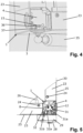
- a gas pressure spring 35 is attached at one end to the rotary fitting 33 and at the other end to the corner connector 1 on the carcass side by means of a screw 36 ( 4 ) fastened, which is screwed through the hole 12 in the lateral angle leg 3 and into a hexagon nut 37 which is inserted in the profile pocket 15 of the angle leg 3 in a form-fitting manner.
- the corner connectors 1 are inserted into end plug-in openings of the frame members 23 and fastened therein by means of self-tapping screws 24 which are screwed into the holes 10 of the U-profile sockets 5 .
- That profile side of the frame rails 23 which forms the outside of the frame has has a raised extension leg 25 which, seen in the profile direction of the rectangular angle 2, is flush with the angle leg 3 of the corner connector 1.
- the offset A corresponds to the wall thickness of the insertion opening of the frame bars 23, so that on the one hand the upper side of the frame bars 23 are flush with the intermediate plate 4 and on the other hand the outside of the frame bars 23 are flush with the angle legs 3 of the corner connectors.
- On the top of the frame bars 23 is a slatted frame 26 and on this in turn a mattress 27 , which is secured laterally by the raised extension legs 25.
- an adjustable foot 28 is attached to each of the two front corner connectors 1 .
- a bearing block 29 is screwed to the respective lateral angle limb 3 of the corner connector 1 by means of a screw which is screwed through the hole 12 in the angle limb 3 into a hexagon nut which is positively inserted into the profile pocket 15 of the angle limb 3, as referenced below on 4 is described.
- the adjustable foot 28 is in turn mounted on the bearing block 29 so that it hangs freely about a horizontal axis and is therefore always aligned vertically due to the force of gravity. In the folded-down position, the adjustable foot 28 stands on the floor.
- the bearing block 29 is additionally screwed to the recess 11 by means of a self-tapping screw.
- a front panel 30 of the bed frame 22 is also shown, which closes the body opening in the folded-up position.
- the holes 13 in the intermediate plate 4 are provided for fastening/securing the front panel 30.
- the front panel 30 can be adjusted in the vertical height direction H after it has been pivoted into the folded-up position.
- one (vertical) leg 31a of an L-angle 31 is screwed to the inside of the front panel 30, the other (horizontal) leg 31b of which protrudes into the interior of the corner connector 1 and is fastened by means of a vertical adjusting screw 32 to the horizontally aligned partition 8 of the corner connector 1 is supported.
- a tool e.g.
Landscapes
- Engineering & Computer Science (AREA)
- General Engineering & Computer Science (AREA)
- Mechanical Engineering (AREA)
- Health & Medical Sciences (AREA)
- General Health & Medical Sciences (AREA)
- Nursing (AREA)
- Invalid Beds And Related Equipment (AREA)
- Buffer Packaging (AREA)
Claims (15)
- Elément monobloc (1) d'assemblage angulaire conçu pour relier deux longerons d'encadrement (23) perpendiculaires l'un à l'autre, comprenant :une cornière rectangulaire (2) munie de deux ailes d'équerre (3),une platine intercalaire (4) encastrée dans ladite cornière rectangulaire (2), à angle droit par rapport à la direction du profilage de cette dernière, etdeux embouts (5) profilés en U, orientés perpendiculairement l'un à l'autre, nantis d'une membrure médiane et de deux membrure latérales (6a-6c) dévolues, respectivement, à l'enfichage dans les orifices d'emboîtement pratiqués aux extrémités des longerons d'encadrement (23),sachant que les membrures médianes (6a) des embouts (5) profilés en U font corps avec la platine intercalaire (4) et s'étendent, par leur face extérieure, parallèlement à ladite platine intercalaire (4),sachant que les unes (6b) des membrures latérales, situées à l'extérieur sur les embouts (5) profilés en U, font respectivement corps avec l'une des ailes d'équerre (3) et s'étendent, par leur face extérieure, parallèlement à la face extérieure de ladite aile d'équerre (3), et que les autres membrures latérales (6c), situées à l'intérieur sur lesdits embouts (5) profilés en U, sont reliées mutuellement au moyen d'un élément de cloisonnement (7) coudé à partir de la platine intercalaire (4), etsachant que lesdites membrures médianes (6a) desdits embouts (5) profilés en U sont percées d'un trou (10) à chaque fois.
- Elément d'assemblage angulaire selon la revendication 1, caractérisé par le fait que les faces extérieures des membrures latérales (6b) extérieures, et/ou les faces extérieures des membrures médianes (6a), présentent à chaque fois un retrait parallèle vers l'intérieur, respectivement par rapport aux faces extérieures des ailes d'équerre (3) et par rapport à la face extérieure de la platine intercalaire (4).
- Elément d'assemblage angulaire selon la revendication 1 ou 2, caractérisé par le fait que la cornière rectangulaire (2), et les membrures latérales (6b, 6c) des deux embouts (5) profilés en U, s'achèvent à une même hauteur.
- Elément d'assemblage angulaire selon l'une des revendications précédentes, caractérisé par le fait que les ailes d'équerre (3) sont percées d'un trou (12) à chaque fois ; et par le fait que deux régions profilées rectangulaires (14), pointant respectivement l'une vers l'autre, font corps avec la face intérieure desdites ailes d'équerre (3), de part et d'autre dudit trou (12), afin de donner naissance à une cavité profilée (15) ouverte dans la direction du profilage de la cornière rectangulaire (2), à distance de la platine intercalaire (4).
- Elément d'assemblage angulaire selon l'une des revendications précédentes, caractérisé par le fait que la platine intercalaire (4) comporte plusieurs trous (13) ; et/ou par le fait que les membrures latérales (6b) extérieures présentent des évidements (11) ouverts, à chaque fois, en direction de l'extrémité libre desdites membrures.
- Elément d'assemblage angulaire selon l'une des revendications précédentes, caractérisé par le fait que les ailes d'équerre (3) sont prolongées, au-dessus de la platine intercalaire (4), par une baguette latérale respective (9) dont la face extérieure présente un retrait parallèle, vers l'intérieur, par rapport à la face extérieure de l'aile d'équerre (3).
- Elément d'assemblage angulaire selon l'une des revendications précédentes, caractérisé par le fait que ledit élément d'assemblage angulaire (1) est ouvert du côté des embouts (5) profilés en U.
- Elément d'assemblage angulaire selon l'une des revendications précédentes, caractérisé par le fait qu'une cloison séparatrice (8) est présente, à chaque fois, entre les embouts (5) profilés en U et la platine intercalaire (4).
- Elément d'assemblage angulaire selon l'une des revendications précédentes, caractérisé par le fait que ledit élément d'assemblage angulaire (1) est réalisé avec symétrie spéculaire par rapport à un plan diagonal (16) de la cornière rectangulaire (2).
- Cadre (22), notamment cadre de lit doté de quatre longerons d'encadrement (23) et de quatre éléments d'assemblage angulaire (1) conformes à l'une des revendications précédentes, les embouts (5) profilés en U desdits éléments d'assemblage angulaire (1) étant enfichés dans des orifices d'emboîtement ouverts aux extrémités desdits longerons d'encadrement (23) et étant fixés, au longeron d'encadrement (23) respectif, par l'intermédiaire de vis (24) vissées dans les trous (10) des membrures médianes (6a) desdits embouts (5) profilés en U.
- Cadre selon la revendication 10, caractérisé par le fait que le côté profilé des longerons d'encadrement (23), qui forme la face extérieure dudit cadre, comporte une aile de prolongement (25) venant à fleur de l'aile d'équerre (3) de l'élément d'assemblage angulaire (1) en observant dans la direction du profilage de la cornière rectangulaire (2).
- Cadre selon la revendication 10 ou 11, caractérisé par le fait que les faces extérieures des ailes d'équerre (3), et la face extérieure dudit cadre côté longerons d'encadrement (23), se trouvent mutuellement en affleurement; et/ou par le fait que la platine intercalaire (4) et lesdits longerons d'encadrement (23) se trouvent mutuellement en affleurement.
- Lit pliant (20) pourvu d'un corps (21), et d'un cadre (22) conforme à l'une des revendications 10 à 12 et monté à pivotement, dans ledit corps (21), entre une position verticale relevée par basculement et une position horizontale abaissée par basculement.
- Lit pliant selon la revendication 13, caractérisé par le fait qu'un piètement réglable (28) ou un ressort, en particulier un ressort à gaz (35), est fixé à l'élément d'assemblage angulaire (1) au moyen d'une vis (36) qui est vissée, en traversant le trou (12) pratiqué dans l'aile d'équerre (3), dans un écrou hexagonal (37) intégré, par complémentarité de formes, dans la cavité profilée (15) de ladite aile d'équerre (3).
- Lit pliant selon la revendication 13 ou 14, caractérisé par un panneau frontal (30) fixé au cadre (22) avec faculté de déplacement en hauteur, sachant qu'une cornière (31), fixée audit panneau frontal (30), repose sur une cloison séparatrice (8) de l'élément d'assemblage angulaire (1) au moyen d'une vis de réglage (32), lorsque ledit cadre (22) du lit est relevé par basculement, et sachant que ladite vis de réglage (32) peut être animée d'une rotation à travers le trou (12) pratiqué dans l'aile d'équerre (3) dudit élément d'assemblage angulaire (1).
Applications Claiming Priority (1)
| Application Number | Priority Date | Filing Date | Title |
|---|---|---|---|
| DE202020106774.5U DE202020106774U1 (de) | 2020-11-25 | 2020-11-25 | Eckverbinder sowie Rahmen und Klappbett mit solch einem Eckverbinder |
Publications (3)
| Publication Number | Publication Date |
|---|---|
| EP4005435A1 EP4005435A1 (fr) | 2022-06-01 |
| EP4005435B1 true EP4005435B1 (fr) | 2023-06-07 |
| EP4005435C0 EP4005435C0 (fr) | 2023-06-07 |
Family
ID=74092162
Family Applications (1)
| Application Number | Title | Priority Date | Filing Date |
|---|---|---|---|
| EP21204897.9A Active EP4005435B1 (fr) | 2020-11-25 | 2021-10-27 | Connecteur angulaire, ainsi que cadre et lit pliant doté d'un tel connecteur angulaire |
Country Status (4)
| Country | Link |
|---|---|
| US (1) | US11644056B2 (fr) |
| EP (1) | EP4005435B1 (fr) |
| DE (1) | DE202020106774U1 (fr) |
| ES (1) | ES2951537T3 (fr) |
Families Citing this family (4)
| Publication number | Priority date | Publication date | Assignee | Title |
|---|---|---|---|---|
| KR102690732B1 (ko) * | 2015-08-14 | 2024-07-31 | 지-모듈러 홀딩, 인크. | 모듈러 빌딩용 커넥터 |
| US20230057573A1 (en) * | 2021-08-23 | 2023-02-23 | Oddello Industries, Llc | Corner Element with Tang Fixation |
| US12203495B2 (en) * | 2022-06-30 | 2025-01-21 | Tung Keng Enterprise Co., Ltd. | Interconnector and a bed using the same |
| USD1080361S1 (en) * | 2023-06-09 | 2025-06-24 | Enviro Framing Systems International Pty Ltd | Furniture corner connector |
Family Cites Families (29)
| Publication number | Priority date | Publication date | Assignee | Title |
|---|---|---|---|---|
| US3357727A (en) * | 1965-11-19 | 1967-12-12 | Gen Electric | Joint assembly for framework structures |
| US3545796A (en) * | 1969-01-22 | 1970-12-08 | John William Nicholls | Framework construction connector |
| SE327313B (fr) * | 1969-05-09 | 1970-08-17 | Hakanssons Ind Ab | |
| US3854831A (en) * | 1970-08-31 | 1974-12-17 | K Gutner | Corner connector for tubular members |
| DE2155234A1 (de) * | 1971-11-06 | 1973-05-10 | Rolf Voelkle | Nach dem baukastenprinzip zusammensetzbares gestell |
| US4027987A (en) * | 1973-06-08 | 1977-06-07 | Kason Hardware Corporation | Joining device for connecting tubes |
| US3886710A (en) * | 1973-06-26 | 1975-06-03 | Classic Games Company Inc | Table construction |
| US3858989A (en) * | 1973-09-10 | 1975-01-07 | Frank P Field | Joint for connecting members |
| SE398140B (sv) * | 1976-02-19 | 1977-12-05 | T W Weibull | Forbindningsanordning |
| US4323319A (en) * | 1977-01-17 | 1982-04-06 | Adams Bevoley C | Structural connecting member |
| CA1114582A (fr) * | 1978-10-24 | 1981-12-22 | Christopher C. Sykes | Joints |
| DE2908475C2 (de) | 1979-03-05 | 1981-10-01 | Karl Lautenschläger KG, Möbelbeschlagfabrik, 6107 Reinheim | Verbindungsbeschlag |
| GB2153955B (en) * | 1982-02-24 | 1986-03-12 | Lionel William King | Assembly system |
| NL8400519A (nl) * | 1984-02-17 | 1985-09-16 | Keen Egbert | Inrichting met uit buisstukken en koppelstukken samengesteld gestel en koppelstuk daarvoor. |
| DE3608984A1 (de) * | 1985-04-12 | 1986-10-23 | G.D S.P.A., Bologna | Staubdichter schrank, besonders fuer elektrische anlagen |
| US4770560A (en) * | 1987-05-29 | 1988-09-13 | Ott Donald E | Self-tapping connector |
| US5066161A (en) * | 1989-05-08 | 1991-11-19 | Pinney Richard C | Framework for cabinet structure |
| IT1314302B1 (it) * | 1999-12-21 | 2002-12-09 | Abb Ricerca Spa | Intelaiatura di supporto per un armadio di quadro elettrico,e relativo armadio |
| US20060182492A1 (en) * | 2005-02-01 | 2006-08-17 | Adam's Specialty Products, Llc | Draw-wedge fasteners |
| DE102006020437A1 (de) * | 2006-05-03 | 2007-11-08 | A.P.S. Arosio S.R.L. | Verbindungsvorrichtung zum Verbinden von mehreren Profilstäben |
| US8297450B2 (en) * | 2008-01-16 | 2012-10-30 | Northrop Grumman Systems Corporation | Modular rack for mounting avionics equipment |
| JP5801784B2 (ja) * | 2012-10-18 | 2015-10-28 | 東芝三菱電機産業システム株式会社 | 連結部材および筐体 |
| DE202014101057U1 (de) | 2014-03-10 | 2015-06-12 | Wellemöbel GmbH | Verbindungsbeschlag und Etagenbett |
| KR102690732B1 (ko) * | 2015-08-14 | 2024-07-31 | 지-모듈러 홀딩, 인크. | 모듈러 빌딩용 커넥터 |
| US9951802B2 (en) * | 2015-10-06 | 2018-04-24 | Adam John Keller | Assembly device |
| CN205747408U (zh) * | 2016-05-31 | 2016-11-30 | 约克广州空调冷冻设备有限公司 | 一种断冷桥空调箱体 |
| US10781838B2 (en) * | 2016-09-07 | 2020-09-22 | Lawrence V. Koepke | Connector device |
| JP6943439B2 (ja) * | 2018-04-13 | 2021-09-29 | 株式会社モービー・ディック | 紙管の連結装置 |
| US20210145172A1 (en) * | 2018-06-15 | 2021-05-20 | Central Graphics And Container Group Ltd. | Modular frame assembly |
-
2020
- 2020-11-25 DE DE202020106774.5U patent/DE202020106774U1/de active Active
-
2021
- 2021-10-27 ES ES21204897T patent/ES2951537T3/es active Active
- 2021-10-27 EP EP21204897.9A patent/EP4005435B1/fr active Active
- 2021-11-18 US US17/455,504 patent/US11644056B2/en active Active
Also Published As
| Publication number | Publication date |
|---|---|
| EP4005435A1 (fr) | 2022-06-01 |
| EP4005435C0 (fr) | 2023-06-07 |
| ES2951537T3 (es) | 2023-10-23 |
| DE202020106774U1 (de) | 2020-12-07 |
| US20220160138A1 (en) | 2022-05-26 |
| US11644056B2 (en) | 2023-05-09 |
Similar Documents
| Publication | Publication Date | Title |
|---|---|---|
| EP4005435B1 (fr) | Connecteur angulaire, ainsi que cadre et lit pliant doté d'un tel connecteur angulaire | |
| EP0994664A1 (fr) | Ensemble d'elements de construction pour meubles | |
| EP3561207B1 (fr) | Moyen de raccordement et partie de meuble | |
| DE3872758T2 (de) | Profil zur verwirklichung eines badewannenpaneelgefueges und gefuege, das mit diesem paneel hergestellt ist. | |
| DE102010017174B4 (de) | Gelenk und klappbares Möbelteil | |
| WO2008061611A1 (fr) | Charnière de porte, en particulier charnière de bord | |
| DE8600534U1 (de) | Klapptisch für die Anbringung an einer Wand | |
| EP1479866B1 (fr) | Meuble avec un élément de fermeture | |
| EP4064937B1 (fr) | Meuble en kit | |
| CH707535A2 (de) | Rahmensystem für eine Insekten- und/oder Pollenschutztür. | |
| EP2801291A1 (fr) | Ferrure de meuble pour former un dispositif coulissant de collecte de déchets | |
| DE102005056625A1 (de) | Wand- oder Türelement | |
| AT509417B1 (de) | Vorrichtung zum befestigen einer funktionseinheit in einem möbelkorpus | |
| WO2010028715A1 (fr) | Porte repliable | |
| AT508414B1 (de) | Träger | |
| DE102013017770A1 (de) | Möbel, mit mindestens einem schubladenartigen Ausziehteil | |
| EP1243212B1 (fr) | Cloison de douche | |
| DE3243865C2 (de) | Türscharnier für Haushaltgeräte | |
| EP1038486B1 (fr) | Jeu de pièces pour cloisons de douches | |
| EP0274569A1 (fr) | Bureau avec tablette supplémentaire | |
| EP2921082A1 (fr) | Meuble destiné à s'asseoir ou s'allonger doté d'un cadre et élément latéral y étant relié | |
| DE102006036487B4 (de) | Rahmenprofil | |
| DE102005028740B4 (de) | Küchenmöbelsystem | |
| DE10311381B3 (de) | Schaltschrank mit einem Rahmengestell und daran angelenkter Schranktüre | |
| DE202012005334U1 (de) | Vorrichtung zum Montieren und Bearbeiten von Bauelementen |
Legal Events
| Date | Code | Title | Description |
|---|---|---|---|
| PUAI | Public reference made under article 153(3) epc to a published international application that has entered the european phase |
Free format text: ORIGINAL CODE: 0009012 |
|
| STAA | Information on the status of an ep patent application or granted ep patent |
Free format text: STATUS: THE APPLICATION HAS BEEN PUBLISHED |
|
| STAA | Information on the status of an ep patent application or granted ep patent |
Free format text: STATUS: REQUEST FOR EXAMINATION WAS MADE |
|
| AK | Designated contracting states |
Kind code of ref document: A1 Designated state(s): AL AT BE BG CH CY CZ DE DK EE ES FI FR GB GR HR HU IE IS IT LI LT LU LV MC MK MT NL NO PL PT RO RS SE SI SK SM TR |
|
| 17P | Request for examination filed |
Effective date: 20220510 |
|
| RBV | Designated contracting states (corrected) |
Designated state(s): AL AT BE BG CH CY CZ DE DK EE ES FI FR GB GR HR HU IE IS IT LI LT LU LV MC MK MT NL NO PL PT RO RS SE SI SK SM TR |
|
| GRAP | Despatch of communication of intention to grant a patent |
Free format text: ORIGINAL CODE: EPIDOSNIGR1 |
|
| STAA | Information on the status of an ep patent application or granted ep patent |
Free format text: STATUS: GRANT OF PATENT IS INTENDED |
|
| INTG | Intention to grant announced |
Effective date: 20221024 |
|
| GRAS | Grant fee paid |
Free format text: ORIGINAL CODE: EPIDOSNIGR3 |
|
| GRAA | (expected) grant |
Free format text: ORIGINAL CODE: 0009210 |
|
| STAA | Information on the status of an ep patent application or granted ep patent |
Free format text: STATUS: THE PATENT HAS BEEN GRANTED |
|
| AK | Designated contracting states |
Kind code of ref document: B1 Designated state(s): AL AT BE BG CH CY CZ DE DK EE ES FI FR GB GR HR HU IE IS IT LI LT LU LV MC MK MT NL NO PL PT RO RS SE SI SK SM TR |
|
| REG | Reference to a national code |
Ref country code: GB Ref legal event code: FG4D Free format text: NOT ENGLISH |
|
| REG | Reference to a national code |
Ref country code: CH Ref legal event code: EP Ref country code: AT Ref legal event code: REF Ref document number: 1572161 Country of ref document: AT Kind code of ref document: T Effective date: 20230615 Ref country code: DE Ref legal event code: R096 Ref document number: 502021000825 Country of ref document: DE |
|
| U01 | Request for unitary effect filed |
Effective date: 20230607 |
|
| U07 | Unitary effect registered |
Designated state(s): AT BE BG DE DK EE FI FR IT LT LU LV MT NL PT SE SI Effective date: 20230612 |
|
| REG | Reference to a national code |
Ref country code: LT Ref legal event code: MG9D |
|
| REG | Reference to a national code |
Ref country code: ES Ref legal event code: FG2A Ref document number: 2951537 Country of ref document: ES Kind code of ref document: T3 Effective date: 20231023 |
|
| PG25 | Lapsed in a contracting state [announced via postgrant information from national office to epo] |
Ref country code: NO Free format text: LAPSE BECAUSE OF FAILURE TO SUBMIT A TRANSLATION OF THE DESCRIPTION OR TO PAY THE FEE WITHIN THE PRESCRIBED TIME-LIMIT Effective date: 20230907 |
|
| U20 | Renewal fee for the european patent with unitary effect paid |
Year of fee payment: 3 Effective date: 20231024 |
|
| PG25 | Lapsed in a contracting state [announced via postgrant information from national office to epo] |
Ref country code: RS Free format text: LAPSE BECAUSE OF FAILURE TO SUBMIT A TRANSLATION OF THE DESCRIPTION OR TO PAY THE FEE WITHIN THE PRESCRIBED TIME-LIMIT Effective date: 20230607 Ref country code: HR Free format text: LAPSE BECAUSE OF FAILURE TO SUBMIT A TRANSLATION OF THE DESCRIPTION OR TO PAY THE FEE WITHIN THE PRESCRIBED TIME-LIMIT Effective date: 20230607 Ref country code: GR Free format text: LAPSE BECAUSE OF FAILURE TO SUBMIT A TRANSLATION OF THE DESCRIPTION OR TO PAY THE FEE WITHIN THE PRESCRIBED TIME-LIMIT Effective date: 20230908 |
|
| PG25 | Lapsed in a contracting state [announced via postgrant information from national office to epo] |
Ref country code: SK Free format text: LAPSE BECAUSE OF FAILURE TO SUBMIT A TRANSLATION OF THE DESCRIPTION OR TO PAY THE FEE WITHIN THE PRESCRIBED TIME-LIMIT Effective date: 20230607 |
|
| PG25 | Lapsed in a contracting state [announced via postgrant information from national office to epo] |
Ref country code: IS Free format text: LAPSE BECAUSE OF FAILURE TO SUBMIT A TRANSLATION OF THE DESCRIPTION OR TO PAY THE FEE WITHIN THE PRESCRIBED TIME-LIMIT Effective date: 20231007 |
|
| PG25 | Lapsed in a contracting state [announced via postgrant information from national office to epo] |
Ref country code: SM Free format text: LAPSE BECAUSE OF FAILURE TO SUBMIT A TRANSLATION OF THE DESCRIPTION OR TO PAY THE FEE WITHIN THE PRESCRIBED TIME-LIMIT Effective date: 20230607 Ref country code: SK Free format text: LAPSE BECAUSE OF FAILURE TO SUBMIT A TRANSLATION OF THE DESCRIPTION OR TO PAY THE FEE WITHIN THE PRESCRIBED TIME-LIMIT Effective date: 20230607 Ref country code: RO Free format text: LAPSE BECAUSE OF FAILURE TO SUBMIT A TRANSLATION OF THE DESCRIPTION OR TO PAY THE FEE WITHIN THE PRESCRIBED TIME-LIMIT Effective date: 20230607 Ref country code: IS Free format text: LAPSE BECAUSE OF FAILURE TO SUBMIT A TRANSLATION OF THE DESCRIPTION OR TO PAY THE FEE WITHIN THE PRESCRIBED TIME-LIMIT Effective date: 20231007 Ref country code: CZ Free format text: LAPSE BECAUSE OF FAILURE TO SUBMIT A TRANSLATION OF THE DESCRIPTION OR TO PAY THE FEE WITHIN THE PRESCRIBED TIME-LIMIT Effective date: 20230607 |
|
| PG25 | Lapsed in a contracting state [announced via postgrant information from national office to epo] |
Ref country code: PL Free format text: LAPSE BECAUSE OF FAILURE TO SUBMIT A TRANSLATION OF THE DESCRIPTION OR TO PAY THE FEE WITHIN THE PRESCRIBED TIME-LIMIT Effective date: 20230607 |
|
| REG | Reference to a national code |
Ref country code: DE Ref legal event code: R097 Ref document number: 502021000825 Country of ref document: DE |
|
| PLBE | No opposition filed within time limit |
Free format text: ORIGINAL CODE: 0009261 |
|
| STAA | Information on the status of an ep patent application or granted ep patent |
Free format text: STATUS: NO OPPOSITION FILED WITHIN TIME LIMIT |
|
| 26N | No opposition filed |
Effective date: 20240308 |
|
| PG25 | Lapsed in a contracting state [announced via postgrant information from national office to epo] |
Ref country code: MC Free format text: LAPSE BECAUSE OF FAILURE TO SUBMIT A TRANSLATION OF THE DESCRIPTION OR TO PAY THE FEE WITHIN THE PRESCRIBED TIME-LIMIT Effective date: 20230607 |
|
| PG25 | Lapsed in a contracting state [announced via postgrant information from national office to epo] |
Ref country code: IE Free format text: LAPSE BECAUSE OF NON-PAYMENT OF DUE FEES Effective date: 20231027 |
|
| PG25 | Lapsed in a contracting state [announced via postgrant information from national office to epo] |
Ref country code: IE Free format text: LAPSE BECAUSE OF NON-PAYMENT OF DUE FEES Effective date: 20231027 |
|
| U20 | Renewal fee for the european patent with unitary effect paid |
Year of fee payment: 4 Effective date: 20241009 |
|
| PGFP | Annual fee paid to national office [announced via postgrant information from national office to epo] |
Ref country code: ES Payment date: 20241118 Year of fee payment: 4 |
|
| PGFP | Annual fee paid to national office [announced via postgrant information from national office to epo] |
Ref country code: CH Payment date: 20241101 Year of fee payment: 4 |
|
| PG25 | Lapsed in a contracting state [announced via postgrant information from national office to epo] |
Ref country code: CY Free format text: LAPSE BECAUSE OF FAILURE TO SUBMIT A TRANSLATION OF THE DESCRIPTION OR TO PAY THE FEE WITHIN THE PRESCRIBED TIME-LIMIT; INVALID AB INITIO Effective date: 20211027 |
|
| U20 | Renewal fee for the european patent with unitary effect paid |
Year of fee payment: 5 Effective date: 20251022 |
|
| PG25 | Lapsed in a contracting state [announced via postgrant information from national office to epo] |
Ref country code: TR Free format text: LAPSE BECAUSE OF FAILURE TO SUBMIT A TRANSLATION OF THE DESCRIPTION OR TO PAY THE FEE WITHIN THE PRESCRIBED TIME-LIMIT Effective date: 20230607 |
|
| PGFP | Annual fee paid to national office [announced via postgrant information from national office to epo] |
Ref country code: GB Payment date: 20251024 Year of fee payment: 5 |
|
| PG25 | Lapsed in a contracting state [announced via postgrant information from national office to epo] |
Ref country code: HU Free format text: LAPSE BECAUSE OF FAILURE TO SUBMIT A TRANSLATION OF THE DESCRIPTION OR TO PAY THE FEE WITHIN THE PRESCRIBED TIME-LIMIT; INVALID AB INITIO Effective date: 20211027 |