EP4005448B1 - Bodenpflegegerät mit zubehörerkennung - Google Patents
Bodenpflegegerät mit zubehörerkennung Download PDFInfo
- Publication number
- EP4005448B1 EP4005448B1 EP21201809.7A EP21201809A EP4005448B1 EP 4005448 B1 EP4005448 B1 EP 4005448B1 EP 21201809 A EP21201809 A EP 21201809A EP 4005448 B1 EP4005448 B1 EP 4005448B1
- Authority
- EP
- European Patent Office
- Prior art keywords
- polarity
- floor care
- accessory
- care device
- supply interface
- Prior art date
- Legal status (The legal status is an assumption and is not a legal conclusion. Google has not performed a legal analysis and makes no representation as to the accuracy of the status listed.)
- Active
Links
Images


Classifications
-
- A—HUMAN NECESSITIES
- A47—FURNITURE; DOMESTIC ARTICLES OR APPLIANCES; COFFEE MILLS; SPICE MILLS; SUCTION CLEANERS IN GENERAL
- A47L—DOMESTIC WASHING OR CLEANING; SUCTION CLEANERS IN GENERAL
- A47L7/00—Suction cleaners adapted for additional purposes; Tables with suction openings for cleaning purposes; Containers for cleaning articles by suction; Suction cleaners adapted to cleaning of brushes; Suction cleaners adapted to taking-up liquids
- A47L7/0095—Suction cleaners or attachments adapted to collect dust or waste from power tools
-
- A—HUMAN NECESSITIES
- A47—FURNITURE; DOMESTIC ARTICLES OR APPLIANCES; COFFEE MILLS; SPICE MILLS; SUCTION CLEANERS IN GENERAL
- A47L—DOMESTIC WASHING OR CLEANING; SUCTION CLEANERS IN GENERAL
- A47L9/00—Details or accessories of suction cleaners, e.g. mechanical means for controlling the suction or for effecting pulsating action; Storing devices specially adapted to suction cleaners or parts thereof; Carrying-vehicles specially adapted for suction cleaners
- A47L9/28—Installation of the electric equipment, e.g. adaptation or attachment to the suction cleaner; Controlling suction cleaners by electric means
- A47L9/2868—Arrangements for power supply of vacuum cleaners or the accessories thereof
Definitions
- the invention relates to a floor care device with improved accessory recognition.
- Floor care devices often have a range of detachable accessories. There are purely passive accessories such as various suction attachments or nozzles, but there are also active accessories such as suction nozzles with motor-driven brushes and/or lighting. However, conventional floor care devices cannot automatically recognize which accessories a user has attached for a floor care operation. If an accessory is not recognized by the floor care device, the device cannot adjust itself to the corresponding accessory, and an active accessory cannot then be variably controlled.
- the invention therefore faces the problem of providing a floor care device with accessory detection that does not require additional wiring for the detection. According to the invention, this problem is solved by a floor care device having the features of patent claim 1 and a system having the features of claim 6 . Advantageous refinements and developments of the invention result from the following dependent claims.
- the invention provides for polarity reversal of the supply of accessories.
- accessories can be detected via the wiring that is already present for the power supply of active accessories.
- the costs that have to be borne as a result are relatively low.
- the measurement can be performed power-free. Both active and passive accessories can be detected.
- the identification can be done separately from the operation by reversing the polarity.
- the DC voltage supply interface includes a 2-wire line.
- the switching device includes a first half-bridge for switching the first polarity and a second half-bridge for switching the second polarity.
- an accessory is identified by detecting an influencing of the DC voltage supply interface in the state of the second polarity by one or more of an ohmic resistor, a short-circuit bridge, an open line end, a capacitor or an inductor.
- the time after which a specific voltage level is reached could be measured. Different capacitors are charged after different times. A coil delays the flow of current.
- the floor care device is battery operated.
- a system comprising a floor care device according to one of the preceding claims and at least one accessory that can be detachably connected to the floor care device and further has an identification element that is set up to influence the DC voltage supply interface in the state of the second polarity to allow identification by the floor care device.
- the accessory has at least one active component which, in the connected state, can be supplied with voltage via the DC voltage supply interface in the state of the first polarity.
- the identification element has one or more of an ohmic resistor, a short-circuit bridge, an open line end, a capacitor or an inductor.
- the detection path and the power path can be addressed separately via appropriate components, so that the motor or other actuators (e.g. nozzle lighting) do not affect the measurement/detection.
- the motor or other actuators e.g. nozzle lighting
- the active component includes a motor, an actuator or a light.
- figure 1 shows schematically a first embodiment.
- the separation between the part of a floor care device 1 (left) and an accessory part 2 (right) connected thereto is indicated here by a dashed line.
- the accessory 2 can be, for example, a suction nozzle with a motor-driven floor brush. Alternatively or additionally, a Lighting or an actuator may be provided (not shown).
- Floor care device 1 and accessory 2 are connected via a DC voltage supply interface 3,4.
- a first half-bridge consisting of power switches T1 and T2 (T2 shown here as diode D1 according to an alternative embodiment) is provided to operate the motor M of the accessory 2 .
- this first half-bridge T1/T2 (D1) is expanded to form a full bridge with the aid of power switches T3 and T4.
- the floor brush or any accessories can be energized with reverse polarity (based on the polarity for normal operation of the motor M), i.e. be controlled accordingly by the control unit 5.
- the motor M is then decoupled via a diode D2 so as not to falsify the measurement via the resistor R2 for identifying the accessory 2.
- the diode D3 can be provided or omitted.
- the resistor R1 is necessary in order to be able to record the generator voltage (back EMF) for speed determination in pulse pauses.
- the voltage level can be adjusted to the measuring range via the optional voltage divider R4/R5.
- the resistor R2 gets different values. Together with the resistor R3, a voltage divider is created.
- the resulting specific accessory voltage can be determined via an ADC channel ADC Zub. of the control unit 5 of the floor care device.
- the speed of the motor can be determined via an ADC channel ADC rpm of the control unit 5 .
- a further power switch T5 is provided, which is switched on when the motor is running and which is switched off via R2 during the measurement. In the event of an error, it can also be switched off via T5.
- UBS is the switched battery voltage.
- Vcc is a regulated extra-low voltage provided by the control unit 5 for supplying the measurement path.
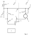
- figure 2 shows schematically a second embodiment relating to the operating state of the accessory 2.
- the separation between the part of a floor care device 1 (left) and an accessory 2 (right) connected thereto is indicated by a dashed line.
- the connection in the form of the DC voltage supply interface 3, 4 can be provided, for example, in/on an intake manifold.
- the half-bridge consisting of T1/T2 generates a PWM signal for the operation of the accessory.
- T2 can also be designed as a diode D1, as shown here.
- the accessory 2 for example the floor brush or any accessory, can be supplied with energy.
- the circuit breaker T5 is turned on when the motor M is running.
- figure 3 shows schematically a third embodiment relating to the identification status of the accessory 2. Again, the separation between the part of a floor care device 1 (left) and an accessory 2 (right) connected thereto is indicated by a dashed line. Furthermore, only the elements relevant to this state are shown.
- T3/T4 When T3/T4 are switched on, a voltage depending on R2 can be measured at the voltage divider R2/R3.
- the specific accessory voltage can be determined via an ADC channel ADC Zub .
- T5 must be switched off for this measurement.
- the measurement takes place via the same two lines, which can be provided in the intake manifold, for example. Only two lines are still required.
Landscapes
- Engineering & Computer Science (AREA)
- Mechanical Engineering (AREA)
- Electric Vacuum Cleaner (AREA)
- Supply And Installment Of Electrical Components (AREA)
- Nozzles For Electric Vacuum Cleaners (AREA)
Description
- Die Erfindung betrifft ein Bodenpflegegerät mit einer verbesserten Zubehörerkennung.
- Bodenpflegegeräte weisen häufig eine Palette von abnehmbaren Zubehörteilen auf. Es gibt dabei rein passive Zubehörteile wie verschiedene Saugvorsätze oder -düsen, aber auch aktive Zubehörteile wie Saugdüsen mit motorisch angetrieben Bürsten und/oder einer Beleuchtung. Herkömmliche Bodenpflegegeräte können jedoch nicht automatisch erkennen, welche Zubehörteile ein Benutzer für einen Bodenpflegevorgang angebracht hat. Wird ein Zubehörteil vom Bodenpflegegerät nicht erkannt, so kann das Gerät sich nicht auf das entsprechende Zubehörteil einstellen, auch kann ein aktives Zubehörteil dann nicht variabel angesteuert werden.
- Aus der
DE 10 2018 126 138 A1 ist ein Erkennen eines Typs einer motorbetriebenen Bürste für einen Staubsauger bekannt, wobei ein Signalmodifikator in Reihe oder parallel zu dem Motor geschaltet ist. Der Signalmodifikator kann eine Induktivität sein, die aufgrund der nötigen Größe jedoch ein teures Bauteil darstellt. Passives Zubehör kann damit nicht erkannt werden. - Weitere Bodenpflegegeräte sind aus der
DE 10 2017 100541 A1 und derDE 10 2017 131460 A1 bekannt. - Eine Erkennung von Zubehörteilen ist grundsätzlich mit einer dafür vorgesehenen zusätzlichen Daten- oder Busleitung denkbar. Das erhöht jedoch den Verkabelungsaufwand, den dafür benötigten Bauraum und somit auch die Kosten des Geräts. Diese Nachteile gilt es zu vermeiden.
- Der Erfindung stellt sich somit das Problem, ein Bodenpflegegerät mit Zubehörerkennung bereitzustellen, das ohne eine zusätzliche Verkabelung für die Erkennung auskommt. Erfindungsgemäß wird dieses Problem durch ein Bodenpflegegerät mit den Merkmalen des Patentanspruchs 1 sowie ein System mit den Merkmalen des Anspruchs 6 gelöst. Vorteilhafte Ausgestaltungen und Weiterbildungen der Erfindung ergeben sich aus den nachfolgenden Unteransprüchen.
- Gemäß einem ersten Aspekt wird ein Bodenpflegegerät bereitgestellt, umfassend:
- eine Gleichspannungsversorgungsschnittstelle für abnehmbare aktive Zubehörteile;
- eine Steuereinheit;
- eine Schalteinrichtung, die dazu eingerichtet ist, die Gleichspannungsversorgungsschnittstelle zwischen einer ersten und einer zweiten Polarität umzuschalten;
- wobei die Steuereinheit dazu eingerichtet ist, mit der Schalteinrichtung die erste Polarität einzustellen, um ein Zubehörteil zu betreiben, oder mit der Schalteinrichtung die zweite Polarität einzustellen, um das Zubehörteil zu identifizieren.
- In der Regel werden aktive Komponenten im Staubsaugerbereich mit einer Gleichspannung versorgt. Die Erfindung sieht eine Umpolung der Zubehörversorgung vor. Mit einem relativ geringen Schaltungsaufwand kann Zubehör über die Verkabelung, die für die Stromversorgung von aktiven Zubehörteilen ohnehin vorhanden ist, erkannt werden. Die Kosten, die deshalb mitgetragen werden müssen, sind relativ gering. Die Messung kann leistungsfrei erfolgen. Es können sowohl aktive als auch passiver Zubehörteile erkannt werden. Die Identifikation kann durch die Umpolung separat von dem Betrieb erfolgen.
- Gemäß einer Ausführungsform umfasst die Gleichspannungsversorgungsschnittstelle eine 2-Draht-Leitung.
- Aufgrund der mit der Erfindung vorgesehenen Umpolung genügt eine 2-Draht-Leitung für die beiden Anwendungsfälle "Betrieb aktiver Zubehörteile" und "Erfassung von aktiven/passiven Zubehörteilen".
- Gemäß einer Ausführungsform umfasst die Schalteinrichtung eine erste Halbbrücke für das Schalten der ersten Polarität und eine zweite Halbbrücke für das Schalten der zweiten Polarität.
- Gemäß einer Ausführungsform erfolgt die Identifikation eines Zubehörteils durch Erfassen einer Beeinflussung der Gleichspannungsversorgungsschnittstelle im Zustand der zweiten Polarität durch eines oder mehrere von einem ohmschen Widerstand, einer Kurzschlussbrücke, einem offenen Leitungsende, einem Kondensator oder einer Induktivität.
- Beispielsweise könnte bei einem Kondensator bzw. einer Spule die Zeit gemessen werden, nach der ein bestimmter Spannungspegel erreicht wird. Verschiedene Kondensatoren werden nach verschiedenen Zeiten aufgeladen. Eine Spule verzögert den Stromfluss.
- Gemäß einer Ausführungsform ist das Bodenpflegegerät akkubetrieben.
- Gemäß einem Aspekt der Erfindung wird ein System bereitgestellt, umfassend ein Bodenpflegegerät nach einem der vorhergehenden Ansprüche sowie mindestens ein Zubehörteil, das abnehmbar mit dem Bodenpflegegerät verbindbar ist und weiter ein Identifikationselement aufweist, das dazu eingerichtet ist, die Gleichspannungsversorgungsschnittstelle im Zustand der zweiten Polarität zu beeinflussen, um eine Identifizierung durch das Bodenpflegegerät zu ermöglichen.
- Gemäß einer Ausführungsform weist das Zubehörteil mindestens eine aktive Komponente auf, die im verbundenen Zustand über die Gleichspannungsversorgungsschnittstelle im Zustand der ersten Polarität mit Spannung versorgt werden kann.
- Gemäß einer Ausführungsform weist das Identifikationselement eines oder mehrere von einem ohmschen Widerstand, einer Kurzschlussbrücke, einem offenen Leitungsende, einem Kondensator oder einer Induktivität auf.
- Gemäß einer Ausführungsform umfasst das System weiter
- eine erste Diode, die so angeordnet ist, dass sich bei der ersten Polarität die aktive Komponente in Durchlassrichtung befindet; und/oder
- eine zweite Diode, die so angeordnet ist, dass sich bei der zweiten Polarität das Identifikationselement in Durchlassrichtung befindet.
- Der Erkennungspfad und der Leistungspfad (Motor/Beleuchtung) sind über entsprechende Bauelemente getrennt ansprechbar, so dass der Motor oder auch andere Aktoren (z.B. Düsenbeleuchtung) die Messung/Erkennung nicht beeinflussen.
- Gemäß einer Ausführungsform umfasst die aktive Komponente einen Motor, einen Aktor oder eine Beleuchtung.
- Ein Ausführungsbeispiel der Erfindung ist in den Zeichnungen rein schematisch dargestellt und wird nachfolgend näher beschrieben. Es zeigt
- Figur 1
- eine erste Ausführungsform;
- Figur 2
- eine zweite Ausführungsform; und
- Figur 3
- eine dritte Ausführungsform.
-
Figur 1 zeigt schematisch eine erste Ausführungsform. Durch eine gestrichelte Linie ist hier die Trennung zwischen dem Teil eines Bodenpflegegeräts 1 (links) und einem damit verbundenen Zubehörteil 2 (rechts) angedeutet. Das Zubehörteil 2 kann beispielsweise eine Saugdüse mit motorbetriebener Bodenbürste sein. Alternativ oder auch zusätzlich kann eine Beleuchtung oder ein Aktor vorgesehen sein (nicht gezeigt). Bodenpflegegerät 1 und Zubehörteil 2 sind über eine Gleichspannungsversorgungsschnittstelle 3, 4 verbunden. - Eine erste Halbbrücke bestehend aus den Leistungsschaltern T1 und T2 (wobei T2 hier gemäß einer alternativen Ausführung als Diode D1 gezeigt ist) ist vorgesehen, um den Motor M des Zubehörteils 2 zu betreiben. Erfindungsgemäß wird diese erste Halbbrücke T1/T2 (D1) mit Hilfe von Leistungsschaltern T3 und T4 zu einer Vollbrücke erweitert. Hiermit kann die Bodenbürste oder beliebiges Zubehör verpolt (bezogen auf die Polung zum normalen Betrieb des Motors M) bestromt werden, d.h. von der Steuereinheit 5 entsprechend angesteuert werden. Der Motor M ist dann über eine Diode D2 entkoppelt, um die Messung über den Widerstand R2 zur Identifizierung des Zubehörteils 2 nicht zu verfälschen. Je nach Auslegung kann die Diode D3 vorgesehen werden oder auch entfallen.
- Der Widerstand R1 ist notwendig, um in Impulspausen die Generatorspannung (Back EMF) zur Drehzahlermittlung erfassen zu können. Über den optionalen Spannungsteiler R4/R5 kann das Spannungsniveau an den Messbereich angepasst werden. Bei verschiedenem Zubehör bekommt der Widerstand R2 verschiedene Werte. Zusammen mit dem Widerstand R3 entsteht ein Spannungsteiler. Über einen ADC-Kanal ADCZub. der Steuereinheit 5 des Bodenpflegegeräts kann die sich daraus ergebende spezifische Zubehörspannung ermittelt werden. Über einen ADC-Kanal ADCrpm der Steuereinheit 5 kann die Drehzahl des Motors bestimmt werden.
- Ein weiterer Leistungsschalter T5 ist vorgesehen, der bei Betrieb des Motors eingeschaltet ist und der während der Messung über R2 abgeschaltet wird. Im Fehlerfall kann ebenfalls über T5 abgeschaltet werden. Für diese Zusatzfunktion muss die Anzahl der Leitungen vom Bodenpflegegerät zum Zubehörteil, beispielsweise im Saugrohr vorgesehen, nicht erhöht werden. UBS ist die geschaltete Batteriespannung. Vcc ist eine von der Steuereinheit 5 zur Verfügung gestellte, geregelte Kleinspannung zur Versorgung des Messpfades.
-
Figur 2 zeigt schematisch eine zweite Ausführungsform betreffend den Betriebszustand des Zubehörteils 2. Wiederum ist hier durch eine gestrichelte Linie die Trennung zwischen dem Teil eines Bodenpflegegeräts 1 (links) und einem damit verbundenen Zubehörteil 2 (rechts) angedeutet. Die Verbindung in Form der Gleichspannungsversorgungsschnittstelle 3, 4 kann beispielsweise in/an einem Saugrohr vorgesehen sein. - Die Halbbrücke bestehend aus T1/T2 generiert für den Betrieb des Zubehörteils ein PWM-Signal. T2 kann auch wie hier gezeigt als Diode D1 ausgeführt sein. Hiermit kann das Zubehörteil 2, also beispielsweise die Bodenbürste oder beliebiges Zubehör, mit Energie versorgt werden. Der Leistungsschalter T5 ist bei Betrieb des Motors M eingeschaltet.
-
Figur 3 zeigt schematisch eine dritte Ausführungsform betreffend den Identifizierungszustand des Zubehörteils 2. Wiederum ist hier durch eine gestrichelte Linie die Trennung zwischen dem Teil eines Bodenpflegegeräts 1 (links) und einem damit verbundenen Zubehörteil 2 (rechts) angedeutet. Weiterhin sind nur die für diesen Zustand relevanten Elemente gezeigt. - Wenn T3/T4 eingeschaltet sind, kann am Spannungsteiler R2/R3 eine Spannung in Abhängigkeit von R2 gemessen werden. Über einen ADC-Kanal ADCZub. der Steuereinheit 5 kann die spezifische Zubehörspannung ermittelt werden. T5 muss bei dieser Messung abgeschaltet werden. Die Messung erfolgt über die gleichen zwei Leitungen, die beispielsweise im Saugrohr vorgesehen sein können. Es werden weiterhin nur zwei Leitungen benötigt.
Claims (10)
- Bodenpflegegerät (1), umfassend:- eine Gleichspannungsversorgungsschnittstelle (3, 4) für abnehmbare aktive Zubehörteile (2);- eine Steuereinheit (5);gekennzeichnet durch- eine Schalteinrichtung (T1, T2, D1, T3, T4), die dazu eingerichtet ist, die Gleichspannungsversorgungsschnittstelle (3, 4) zwischen einer ersten und einer zweiten Polarität umzuschalten;- wobei die Steuereinheit (5) dazu eingerichtet ist, mit der Schalteinrichtung (T1, T2, D1, T3, T4) die erste Polarität einzustellen, um ein Zubehörteil (2) zu betreiben, oder mit der Schalteinrichtung (T1, T2, D1, T3, T4) die zweite Polarität einzustellen, um das Zubehörteil (2) zu identifizieren.
- Bodenpflegegerät (1) nach Anspruch 1, wobei die Gleichspannungsversorgungsschnittstelle (3, 4) eine 2-Draht-Leitung umfasst.
- Bodenpflegegerät (1) nach Anspruch 1 oder 2, wobei die Schalteinrichtung (T1, T2, D1, T3, T4) eine erste Halbbrücke (T1, T2, D1) für das Schalten der ersten Polarität und eine zweite Halbbrücke (T3, T4) für das Schalten der zweiten Polarität umfasst.
- Bodenpflegegerät (1) nach einem der vorhergehenden Ansprüche, wobei die Identifikation eines Zubehörteils (2) durch Erfassen einer Beeinflussung der Gleichspannungsversorgungsschnittstelle (3, 4) im Zustand der zweiten Polarität durch eines oder mehrere von einem ohmschen Widerstand (R2), einer Kurzschlussbrücke, einem offenen Leitungsende, einem Kondensator oder einer Induktivität erfolgt.
- Bodenpflegegerät (1) nach einem der vorhergehenden Ansprüche, wobei das Bodenpflegegerät (1) akkubetrieben ist.
- System, umfassend ein Bodenpflegegerät nach einem der vorhergehenden Ansprüche sowie mindestens ein Zubehörteil (2), das abnehmbar mit dem Bodenpflegegerät (1) verbindbar ist und weiter ein Identifikationselement (R2) aufweist, das dazu eingerichtet ist, die Gleichspannungsversorgungsschnittstelle (3, 4) im Zustand der zweiten Polarität zu beeinflussen, um eine Identifizierung durch das Bodenpflegegerät (1) zu ermöglichen.
- System nach Anspruch 6, wobei das Zubehörteil (2) mindestens eine aktive Komponente (M) aufweist, die im verbundenen Zustand über die Gleichspannungsversorgungsschnittstelle (3, 4) im Zustand der ersten Polarität mit Spannung versorgt werden kann.
- System nach Anspruch 6 oder 7, wobei das Identifikationselement eines oder mehrere aufweist von einem ohmschen Widerstand (R2), einer Kurzschlussbrücke, einem offenen Leitungsende, einem Kondensator oder einer Induktivität.
- System nach einem der Ansprüche 6 bis 8, weiter umfassend- eine erste Diode (D2), die so angeordnet ist, dass sich bei der ersten Polarität die aktive Komponente (M) in Durchlassrichtung befindet; und/oder- eine zweite Diode (D3), die so angeordnet ist, dass sich bei der zweiten Polarität das Identifikationselement (R2) in Durchlassrichtung befindet.
- System nach einem der Ansprüche 7 bis 8, wobei die aktive Komponente einen Motor (M), einen Aktor oder eine Beleuchtung umfasst.
Applications Claiming Priority (1)
| Application Number | Priority Date | Filing Date | Title |
|---|---|---|---|
| DE102020129053.5A DE102020129053A1 (de) | 2020-11-04 | 2020-11-04 | Bodenpflegegerät mit Zubehörerkennung |
Publications (2)
| Publication Number | Publication Date |
|---|---|
| EP4005448A1 EP4005448A1 (de) | 2022-06-01 |
| EP4005448B1 true EP4005448B1 (de) | 2023-08-09 |
Family
ID=78087115
Family Applications (1)
| Application Number | Title | Priority Date | Filing Date |
|---|---|---|---|
| EP21201809.7A Active EP4005448B1 (de) | 2020-11-04 | 2021-10-11 | Bodenpflegegerät mit zubehörerkennung |
Country Status (4)
| Country | Link |
|---|---|
| EP (1) | EP4005448B1 (de) |
| DE (1) | DE102020129053A1 (de) |
| ES (1) | ES2952685T3 (de) |
| PL (1) | PL4005448T3 (de) |
Family Cites Families (3)
| Publication number | Priority date | Publication date | Assignee | Title |
|---|---|---|---|---|
| DE102017100541A1 (de) * | 2017-01-12 | 2018-07-12 | Metabowerke Gmbh | Mehrzweckstaubsauger |
| DE102017131460A1 (de) * | 2017-06-08 | 2018-12-13 | Festool Gmbh | Konfigurationsvorrichtung für ein System mit Werkzeugmaschine und Staubsauger |
| DE102018126138A1 (de) | 2018-10-22 | 2020-04-23 | Miele & Cie. Kg | Verfahren und Vorrichtung zum Erkennen eines Typs einer motorbetriebenen Bürste für einen Staubsauger, Verfahren und Vorrichtung zum Betreiben eines Staubsaugers, motorbetriebene Bürste für einen Staubsauger und Staubsauger |
-
2020
- 2020-11-04 DE DE102020129053.5A patent/DE102020129053A1/de not_active Withdrawn
-
2021
- 2021-10-11 EP EP21201809.7A patent/EP4005448B1/de active Active
- 2021-10-11 PL PL21201809.7T patent/PL4005448T3/pl unknown
- 2021-10-11 ES ES21201809T patent/ES2952685T3/es active Active
Also Published As
| Publication number | Publication date |
|---|---|
| EP4005448A1 (de) | 2022-06-01 |
| ES2952685T3 (es) | 2023-11-03 |
| DE102020129053A1 (de) | 2022-05-05 |
| PL4005448T3 (pl) | 2023-12-11 |
Similar Documents
| Publication | Publication Date | Title |
|---|---|---|
| DE102008023857A1 (de) | Halbleiterelement-Treiberschaltung | |
| DE202008010423U1 (de) | Kraftfahrzeugtürverschluss mit einer Schaltungsanordnung | |
| DE102013217271A1 (de) | Fahrzeugfensteröffnungs- und -schließsteuervorrichtung | |
| EP1839388A1 (de) | Steuerschatung für einen elektronisch kommutierten motor | |
| DE102014204783A1 (de) | Motortreibervorrichtung | |
| DE19813797B4 (de) | Vorrichtung zur Steuerung des Stromflusses durch eine Reihe induktiver Lasten | |
| DE19525897C1 (de) | Elektrische Schaltungsanordnung | |
| DE19704089A1 (de) | Verfahren zur Steuerung eines Zerhacker(Chopper)-Treibers und Schaltungsanordnung zur Durchführung des Verfahrens | |
| EP1859288B1 (de) | Verfahren und schaltungsanordnung zur detektion eines leitungsbruches | |
| WO2007054149A1 (de) | Schaltungsanordnung und ein verfahren zur galvanisch getrennten ansteuerung eines halbleiterschalters | |
| EP4005448B1 (de) | Bodenpflegegerät mit zubehörerkennung | |
| DE102004022858A1 (de) | System und Verfahren zur Drehzahlregelungs- und Stillstandsschutzkombination für Elektromotoren wie etwa in Motorkühlanwendungen | |
| WO2016001289A1 (de) | Aktuator mit positionssensor | |
| DE102014211647A1 (de) | Vorrichtung zum Erkennen einer Schalterstellung | |
| DE2930559A1 (de) | Verfahren und schaltungsanordnung zur steuerung der drehzahl eines gleichstrommotors | |
| EP3063505B1 (de) | Positionssensor für die erfassung einer lageposition eines aktuators | |
| DE19614755A1 (de) | Mehrphasiger, bürstenloser Gleichstrommotor | |
| DE112017002977B4 (de) | Elektronische steuereinheit | |
| DE102007036668A1 (de) | Schaltungsanordnung zur Überwachung einer Tachoeinrichtung für einen Antriebsmotor einer Trommel einer Waschmaschine | |
| DE102008022661A1 (de) | Motor- Steuerungs- Verfahren und Vorrichtung dafür | |
| EP1396925B1 (de) | Ladeschaltung für einen Umrichter | |
| DE19853416C2 (de) | Schaltungsanordnung zur Pegelumsetzung binärer Signale bei der Steuerung einer drucktechnischen Maschine | |
| DE102021101884B4 (de) | Verfahren zur Phasenstrommessung und Steuerschaltung | |
| DE10307823A1 (de) | Schaltungsanordnung zur Lüfterregelung | |
| DE102004041466B4 (de) | Elektromotorischer Stellantrieb mit Steuereinheit für Zwischenposition und Steuerverfahren |
Legal Events
| Date | Code | Title | Description |
|---|---|---|---|
| PUAI | Public reference made under article 153(3) epc to a published international application that has entered the european phase |
Free format text: ORIGINAL CODE: 0009012 |
|
| STAA | Information on the status of an ep patent application or granted ep patent |
Free format text: STATUS: THE APPLICATION HAS BEEN PUBLISHED |
|
| AK | Designated contracting states |
Kind code of ref document: A1 Designated state(s): AL AT BE BG CH CY CZ DE DK EE ES FI FR GB GR HR HU IE IS IT LI LT LU LV MC MK MT NL NO PL PT RO RS SE SI SK SM TR |
|
| STAA | Information on the status of an ep patent application or granted ep patent |
Free format text: STATUS: REQUEST FOR EXAMINATION WAS MADE |
|
| 17P | Request for examination filed |
Effective date: 20221201 |
|
| RBV | Designated contracting states (corrected) |
Designated state(s): AL AT BE BG CH CY CZ DE DK EE ES FI FR GB GR HR HU IE IS IT LI LT LU LV MC MK MT NL NO PL PT RO RS SE SI SK SM TR |
|
| GRAP | Despatch of communication of intention to grant a patent |
Free format text: ORIGINAL CODE: EPIDOSNIGR1 |
|
| STAA | Information on the status of an ep patent application or granted ep patent |
Free format text: STATUS: GRANT OF PATENT IS INTENDED |
|
| RIC1 | Information provided on ipc code assigned before grant |
Ipc: A47L 9/28 20060101ALI20230418BHEP Ipc: A47L 7/00 20060101AFI20230418BHEP |
|
| INTG | Intention to grant announced |
Effective date: 20230515 |
|
| GRAS | Grant fee paid |
Free format text: ORIGINAL CODE: EPIDOSNIGR3 |
|
| GRAA | (expected) grant |
Free format text: ORIGINAL CODE: 0009210 |
|
| STAA | Information on the status of an ep patent application or granted ep patent |
Free format text: STATUS: THE PATENT HAS BEEN GRANTED |
|
| REG | Reference to a national code |
Ref country code: DE Ref legal event code: R084 Ref document number: 502021001210 Country of ref document: DE |
|
| AK | Designated contracting states |
Kind code of ref document: B1 Designated state(s): AL AT BE BG CH CY CZ DE DK EE ES FI FR GB GR HR HU IE IS IT LI LT LU LV MC MK MT NL NO PL PT RO RS SE SI SK SM TR |
|
| REG | Reference to a national code |
Ref country code: GB Ref legal event code: FG4D Free format text: NOT ENGLISH |
|
| REG | Reference to a national code |
Ref country code: CH Ref legal event code: EP |
|
| REG | Reference to a national code |
Ref country code: IE Ref legal event code: FG4D Free format text: LANGUAGE OF EP DOCUMENT: GERMAN |
|
| REG | Reference to a national code |
Ref country code: DE Ref legal event code: R096 Ref document number: 502021001210 Country of ref document: DE |
|
| REG | Reference to a national code |
Ref country code: GB Ref legal event code: 746 Effective date: 20230919 |
|
| REG | Reference to a national code |
Ref country code: ES Ref legal event code: FG2A Ref document number: 2952685 Country of ref document: ES Kind code of ref document: T3 Effective date: 20231103 |
|
| REG | Reference to a national code |
Ref country code: LT Ref legal event code: MG9D |
|
| REG | Reference to a national code |
Ref country code: NL Ref legal event code: MP Effective date: 20230809 |
|
| PG25 | Lapsed in a contracting state [announced via postgrant information from national office to epo] |
Ref country code: GR Free format text: LAPSE BECAUSE OF FAILURE TO SUBMIT A TRANSLATION OF THE DESCRIPTION OR TO PAY THE FEE WITHIN THE PRESCRIBED TIME-LIMIT Effective date: 20231110 |
|
| PG25 | Lapsed in a contracting state [announced via postgrant information from national office to epo] |
Ref country code: IS Free format text: LAPSE BECAUSE OF FAILURE TO SUBMIT A TRANSLATION OF THE DESCRIPTION OR TO PAY THE FEE WITHIN THE PRESCRIBED TIME-LIMIT Effective date: 20231209 |
|
| PG25 | Lapsed in a contracting state [announced via postgrant information from national office to epo] |
Ref country code: SE Free format text: LAPSE BECAUSE OF FAILURE TO SUBMIT A TRANSLATION OF THE DESCRIPTION OR TO PAY THE FEE WITHIN THE PRESCRIBED TIME-LIMIT Effective date: 20230809 Ref country code: RS Free format text: LAPSE BECAUSE OF FAILURE TO SUBMIT A TRANSLATION OF THE DESCRIPTION OR TO PAY THE FEE WITHIN THE PRESCRIBED TIME-LIMIT Effective date: 20230809 Ref country code: PT Free format text: LAPSE BECAUSE OF FAILURE TO SUBMIT A TRANSLATION OF THE DESCRIPTION OR TO PAY THE FEE WITHIN THE PRESCRIBED TIME-LIMIT Effective date: 20231211 Ref country code: NO Free format text: LAPSE BECAUSE OF FAILURE TO SUBMIT A TRANSLATION OF THE DESCRIPTION OR TO PAY THE FEE WITHIN THE PRESCRIBED TIME-LIMIT Effective date: 20231109 Ref country code: NL Free format text: LAPSE BECAUSE OF FAILURE TO SUBMIT A TRANSLATION OF THE DESCRIPTION OR TO PAY THE FEE WITHIN THE PRESCRIBED TIME-LIMIT Effective date: 20230809 Ref country code: LV Free format text: LAPSE BECAUSE OF FAILURE TO SUBMIT A TRANSLATION OF THE DESCRIPTION OR TO PAY THE FEE WITHIN THE PRESCRIBED TIME-LIMIT Effective date: 20230809 Ref country code: LT Free format text: LAPSE BECAUSE OF FAILURE TO SUBMIT A TRANSLATION OF THE DESCRIPTION OR TO PAY THE FEE WITHIN THE PRESCRIBED TIME-LIMIT Effective date: 20230809 Ref country code: IS Free format text: LAPSE BECAUSE OF FAILURE TO SUBMIT A TRANSLATION OF THE DESCRIPTION OR TO PAY THE FEE WITHIN THE PRESCRIBED TIME-LIMIT Effective date: 20231209 Ref country code: HR Free format text: LAPSE BECAUSE OF FAILURE TO SUBMIT A TRANSLATION OF THE DESCRIPTION OR TO PAY THE FEE WITHIN THE PRESCRIBED TIME-LIMIT Effective date: 20230809 Ref country code: GR Free format text: LAPSE BECAUSE OF FAILURE TO SUBMIT A TRANSLATION OF THE DESCRIPTION OR TO PAY THE FEE WITHIN THE PRESCRIBED TIME-LIMIT Effective date: 20231110 Ref country code: FI Free format text: LAPSE BECAUSE OF FAILURE TO SUBMIT A TRANSLATION OF THE DESCRIPTION OR TO PAY THE FEE WITHIN THE PRESCRIBED TIME-LIMIT Effective date: 20230809 |
|
| REG | Reference to a national code |
Ref country code: ES Ref legal event code: GC2A Effective date: 20240410 |
|
| PG25 | Lapsed in a contracting state [announced via postgrant information from national office to epo] |
Ref country code: SM Free format text: LAPSE BECAUSE OF FAILURE TO SUBMIT A TRANSLATION OF THE DESCRIPTION OR TO PAY THE FEE WITHIN THE PRESCRIBED TIME-LIMIT Effective date: 20230809 Ref country code: RO Free format text: LAPSE BECAUSE OF FAILURE TO SUBMIT A TRANSLATION OF THE DESCRIPTION OR TO PAY THE FEE WITHIN THE PRESCRIBED TIME-LIMIT Effective date: 20230809 Ref country code: EE Free format text: LAPSE BECAUSE OF FAILURE TO SUBMIT A TRANSLATION OF THE DESCRIPTION OR TO PAY THE FEE WITHIN THE PRESCRIBED TIME-LIMIT Effective date: 20230809 Ref country code: DK Free format text: LAPSE BECAUSE OF FAILURE TO SUBMIT A TRANSLATION OF THE DESCRIPTION OR TO PAY THE FEE WITHIN THE PRESCRIBED TIME-LIMIT Effective date: 20230809 Ref country code: CZ Free format text: LAPSE BECAUSE OF FAILURE TO SUBMIT A TRANSLATION OF THE DESCRIPTION OR TO PAY THE FEE WITHIN THE PRESCRIBED TIME-LIMIT Effective date: 20230809 Ref country code: SK Free format text: LAPSE BECAUSE OF FAILURE TO SUBMIT A TRANSLATION OF THE DESCRIPTION OR TO PAY THE FEE WITHIN THE PRESCRIBED TIME-LIMIT Effective date: 20230809 |
|
| REG | Reference to a national code |
Ref country code: DE Ref legal event code: R097 Ref document number: 502021001210 Country of ref document: DE |
|
| PG25 | Lapsed in a contracting state [announced via postgrant information from national office to epo] |
Ref country code: MC Free format text: LAPSE BECAUSE OF FAILURE TO SUBMIT A TRANSLATION OF THE DESCRIPTION OR TO PAY THE FEE WITHIN THE PRESCRIBED TIME-LIMIT Effective date: 20230809 |
|
| PLBE | No opposition filed within time limit |
Free format text: ORIGINAL CODE: 0009261 |
|
| STAA | Information on the status of an ep patent application or granted ep patent |
Free format text: STATUS: NO OPPOSITION FILED WITHIN TIME LIMIT |
|
| REG | Reference to a national code |
Ref country code: BE Ref legal event code: MM Effective date: 20231031 |
|
| PG25 | Lapsed in a contracting state [announced via postgrant information from national office to epo] |
Ref country code: LU Free format text: LAPSE BECAUSE OF NON-PAYMENT OF DUE FEES Effective date: 20231011 |
|
| PG25 | Lapsed in a contracting state [announced via postgrant information from national office to epo] |
Ref country code: LU Free format text: LAPSE BECAUSE OF NON-PAYMENT OF DUE FEES Effective date: 20231011 |
|
| 26N | No opposition filed |
Effective date: 20240513 |
|
| PG25 | Lapsed in a contracting state [announced via postgrant information from national office to epo] |
Ref country code: SI Free format text: LAPSE BECAUSE OF FAILURE TO SUBMIT A TRANSLATION OF THE DESCRIPTION OR TO PAY THE FEE WITHIN THE PRESCRIBED TIME-LIMIT Effective date: 20230809 |
|
| PG25 | Lapsed in a contracting state [announced via postgrant information from national office to epo] |
Ref country code: BE Free format text: LAPSE BECAUSE OF NON-PAYMENT OF DUE FEES Effective date: 20231031 |
|
| PG25 | Lapsed in a contracting state [announced via postgrant information from national office to epo] |
Ref country code: IE Free format text: LAPSE BECAUSE OF NON-PAYMENT OF DUE FEES Effective date: 20231011 |
|
| PG25 | Lapsed in a contracting state [announced via postgrant information from national office to epo] |
Ref country code: IE Free format text: LAPSE BECAUSE OF NON-PAYMENT OF DUE FEES Effective date: 20231011 |
|
| PG25 | Lapsed in a contracting state [announced via postgrant information from national office to epo] |
Ref country code: BG Free format text: LAPSE BECAUSE OF FAILURE TO SUBMIT A TRANSLATION OF THE DESCRIPTION OR TO PAY THE FEE WITHIN THE PRESCRIBED TIME-LIMIT Effective date: 20230809 |
|
| PG25 | Lapsed in a contracting state [announced via postgrant information from national office to epo] |
Ref country code: BG Free format text: LAPSE BECAUSE OF FAILURE TO SUBMIT A TRANSLATION OF THE DESCRIPTION OR TO PAY THE FEE WITHIN THE PRESCRIBED TIME-LIMIT Effective date: 20230809 |
|
| REG | Reference to a national code |
Ref country code: CH Ref legal event code: PL |
|
| PG25 | Lapsed in a contracting state [announced via postgrant information from national office to epo] |
Ref country code: CH Free format text: LAPSE BECAUSE OF NON-PAYMENT OF DUE FEES Effective date: 20241031 |
|
| PG25 | Lapsed in a contracting state [announced via postgrant information from national office to epo] |
Ref country code: CY Free format text: LAPSE BECAUSE OF FAILURE TO SUBMIT A TRANSLATION OF THE DESCRIPTION OR TO PAY THE FEE WITHIN THE PRESCRIBED TIME-LIMIT; INVALID AB INITIO Effective date: 20211011 |
|
| PGFP | Annual fee paid to national office [announced via postgrant information from national office to epo] |
Ref country code: TR Payment date: 20250929 Year of fee payment: 5 Ref country code: PL Payment date: 20250930 Year of fee payment: 5 |
|
| PGFP | Annual fee paid to national office [announced via postgrant information from national office to epo] |
Ref country code: DE Payment date: 20251031 Year of fee payment: 5 |
|
| PGFP | Annual fee paid to national office [announced via postgrant information from national office to epo] |
Ref country code: GB Payment date: 20251023 Year of fee payment: 5 |
|
| PGFP | Annual fee paid to national office [announced via postgrant information from national office to epo] |
Ref country code: AT Payment date: 20260113 Year of fee payment: 5 |
|
| PGFP | Annual fee paid to national office [announced via postgrant information from national office to epo] |
Ref country code: IT Payment date: 20251022 Year of fee payment: 5 |
|
| PGFP | Annual fee paid to national office [announced via postgrant information from national office to epo] |
Ref country code: FR Payment date: 20251027 Year of fee payment: 5 |
|
| PGFP | Annual fee paid to national office [announced via postgrant information from national office to epo] |
Ref country code: ES Payment date: 20251118 Year of fee payment: 5 |
|
| PG25 | Lapsed in a contracting state [announced via postgrant information from national office to epo] |
Ref country code: HU Free format text: LAPSE BECAUSE OF FAILURE TO SUBMIT A TRANSLATION OF THE DESCRIPTION OR TO PAY THE FEE WITHIN THE PRESCRIBED TIME-LIMIT; INVALID AB INITIO Effective date: 20211011 |