EP4005518B1 - Kathetersystem - Google Patents
Kathetersystem Download PDFInfo
- Publication number
- EP4005518B1 EP4005518B1 EP20846752.2A EP20846752A EP4005518B1 EP 4005518 B1 EP4005518 B1 EP 4005518B1 EP 20846752 A EP20846752 A EP 20846752A EP 4005518 B1 EP4005518 B1 EP 4005518B1
- Authority
- EP
- European Patent Office
- Prior art keywords
- catheter
- fastening
- magnet
- coupled
- magnetic
- Prior art date
- Legal status (The legal status is an assumption and is not a legal conclusion. Google has not performed a legal analysis and makes no representation as to the accuracy of the status listed.)
- Active
Links
Images



Classifications
-
- A—HUMAN NECESSITIES
- A61—MEDICAL OR VETERINARY SCIENCE; HYGIENE
- A61B—DIAGNOSIS; SURGERY; IDENTIFICATION
- A61B17/00—Surgical instruments, devices or methods
- A61B17/32—Surgical cutting instruments
- A61B17/3205—Excision instruments
- A61B17/3207—Atherectomy devices working by cutting or abrading; Similar devices specially adapted for non-vascular obstructions
- A61B17/320758—Atherectomy devices working by cutting or abrading; Similar devices specially adapted for non-vascular obstructions with a rotating cutting instrument, e.g. motor driven
-
- A—HUMAN NECESSITIES
- A61—MEDICAL OR VETERINARY SCIENCE; HYGIENE
- A61B—DIAGNOSIS; SURGERY; IDENTIFICATION
- A61B34/00—Computer-aided surgery; Manipulators or robots specially adapted for use in surgery
- A61B34/30—Surgical robots
-
- A—HUMAN NECESSITIES
- A61—MEDICAL OR VETERINARY SCIENCE; HYGIENE
- A61B—DIAGNOSIS; SURGERY; IDENTIFICATION
- A61B34/00—Computer-aided surgery; Manipulators or robots specially adapted for use in surgery
- A61B34/70—Manipulators specially adapted for use in surgery
- A61B34/73—Manipulators for magnetic surgery
-
- A—HUMAN NECESSITIES
- A61—MEDICAL OR VETERINARY SCIENCE; HYGIENE
- A61F—FILTERS IMPLANTABLE INTO BLOOD VESSELS; PROSTHESES; DEVICES PROVIDING PATENCY TO, OR PREVENTING COLLAPSING OF, TUBULAR STRUCTURES OF THE BODY, e.g. STENTS; ORTHOPAEDIC, NURSING OR CONTRACEPTIVE DEVICES; FOMENTATION; TREATMENT OR PROTECTION OF EYES OR EARS; BANDAGES, DRESSINGS OR ABSORBENT PADS; FIRST-AID KITS
- A61F2/00—Filters implantable into blood vessels; Prostheses, i.e. artificial substitutes or replacements for parts of the body; Appliances for connecting them with the body; Devices providing patency to, or preventing collapsing of, tubular structures of the body, e.g. stents
- A61F2/95—Instruments specially adapted for placement or removal of stents or stent-grafts
- A61F2/958—Inflatable balloons for placing stents or stent-grafts
-
- A—HUMAN NECESSITIES
- A61—MEDICAL OR VETERINARY SCIENCE; HYGIENE
- A61M—DEVICES FOR INTRODUCING MEDIA INTO, OR ONTO, THE BODY; DEVICES FOR TRANSDUCING BODY MEDIA OR FOR TAKING MEDIA FROM THE BODY; DEVICES FOR PRODUCING OR ENDING SLEEP OR STUPOR
- A61M25/00—Catheters; Hollow probes
- A61M25/01—Introducing, guiding, advancing, emplacing or holding catheters
- A61M25/0105—Steering means as part of the catheter or advancing means; Markers for positioning
- A61M25/0116—Steering means as part of the catheter or advancing means; Markers for positioning self-propelled, e.g. autonomous robots
-
- A—HUMAN NECESSITIES
- A61—MEDICAL OR VETERINARY SCIENCE; HYGIENE
- A61M—DEVICES FOR INTRODUCING MEDIA INTO, OR ONTO, THE BODY; DEVICES FOR TRANSDUCING BODY MEDIA OR FOR TAKING MEDIA FROM THE BODY; DEVICES FOR PRODUCING OR ENDING SLEEP OR STUPOR
- A61M25/00—Catheters; Hollow probes
- A61M25/01—Introducing, guiding, advancing, emplacing or holding catheters
- A61M25/0105—Steering means as part of the catheter or advancing means; Markers for positioning
- A61M25/0127—Magnetic means; Magnetic markers
-
- A—HUMAN NECESSITIES
- A61—MEDICAL OR VETERINARY SCIENCE; HYGIENE
- A61B—DIAGNOSIS; SURGERY; IDENTIFICATION
- A61B17/00—Surgical instruments, devices or methods
- A61B17/00234—Surgical instruments, devices or methods for minimally invasive surgery
- A61B2017/00345—Micromachines, nanomachines, microsystems
-
- A—HUMAN NECESSITIES
- A61—MEDICAL OR VETERINARY SCIENCE; HYGIENE
- A61B—DIAGNOSIS; SURGERY; IDENTIFICATION
- A61B17/00—Surgical instruments, devices or methods
- A61B2017/00477—Coupling
-
- A—HUMAN NECESSITIES
- A61—MEDICAL OR VETERINARY SCIENCE; HYGIENE
- A61B—DIAGNOSIS; SURGERY; IDENTIFICATION
- A61B17/00—Surgical instruments, devices or methods
- A61B2017/00535—Surgical instruments, devices or methods pneumatically or hydraulically operated
- A61B2017/00557—Surgical instruments, devices or methods pneumatically or hydraulically operated inflatable
-
- A—HUMAN NECESSITIES
- A61—MEDICAL OR VETERINARY SCIENCE; HYGIENE
- A61B—DIAGNOSIS; SURGERY; IDENTIFICATION
- A61B17/00—Surgical instruments, devices or methods
- A61B2017/00831—Material properties
- A61B2017/00876—Material properties magnetic
-
- A—HUMAN NECESSITIES
- A61—MEDICAL OR VETERINARY SCIENCE; HYGIENE
- A61B—DIAGNOSIS; SURGERY; IDENTIFICATION
- A61B17/00—Surgical instruments, devices or methods
- A61B17/22—Implements for squeezing-off ulcers or the like on inner organs of the body; Implements for scraping-out cavities of body organs, e.g. bones; for invasive removal or destruction of calculus using mechanical vibrations; for removing obstructions in blood vessels, not otherwise provided for
- A61B2017/22051—Implements for squeezing-off ulcers or the like on inner organs of the body; Implements for scraping-out cavities of body organs, e.g. bones; for invasive removal or destruction of calculus using mechanical vibrations; for removing obstructions in blood vessels, not otherwise provided for with an inflatable part, e.g. balloon, for positioning, blocking, or immobilisation
- A61B2017/22065—Functions of balloons
- A61B2017/22067—Blocking; Occlusion
-
- A—HUMAN NECESSITIES
- A61—MEDICAL OR VETERINARY SCIENCE; HYGIENE
- A61B—DIAGNOSIS; SURGERY; IDENTIFICATION
- A61B17/00—Surgical instruments, devices or methods
- A61B17/22—Implements for squeezing-off ulcers or the like on inner organs of the body; Implements for scraping-out cavities of body organs, e.g. bones; for invasive removal or destruction of calculus using mechanical vibrations; for removing obstructions in blood vessels, not otherwise provided for
- A61B2017/22079—Implements for squeezing-off ulcers or the like on inner organs of the body; Implements for scraping-out cavities of body organs, e.g. bones; for invasive removal or destruction of calculus using mechanical vibrations; for removing obstructions in blood vessels, not otherwise provided for with suction of debris
-
- A—HUMAN NECESSITIES
- A61—MEDICAL OR VETERINARY SCIENCE; HYGIENE
- A61B—DIAGNOSIS; SURGERY; IDENTIFICATION
- A61B17/00—Surgical instruments, devices or methods
- A61B17/32—Surgical cutting instruments
- A61B17/3205—Excision instruments
- A61B17/3207—Atherectomy devices working by cutting or abrading; Similar devices specially adapted for non-vascular obstructions
- A61B17/320758—Atherectomy devices working by cutting or abrading; Similar devices specially adapted for non-vascular obstructions with a rotating cutting instrument, e.g. motor driven
- A61B2017/320775—Morcellators, impeller or propeller like means
-
- A—HUMAN NECESSITIES
- A61—MEDICAL OR VETERINARY SCIENCE; HYGIENE
- A61B—DIAGNOSIS; SURGERY; IDENTIFICATION
- A61B34/00—Computer-aided surgery; Manipulators or robots specially adapted for use in surgery
- A61B34/30—Surgical robots
- A61B2034/301—Surgical robots for introducing or steering flexible instruments inserted into the body, e.g. catheters or endoscopes
-
- A—HUMAN NECESSITIES
- A61—MEDICAL OR VETERINARY SCIENCE; HYGIENE
- A61B—DIAGNOSIS; SURGERY; IDENTIFICATION
- A61B34/00—Computer-aided surgery; Manipulators or robots specially adapted for use in surgery
- A61B34/30—Surgical robots
- A61B2034/303—Surgical robots specifically adapted for manipulations within body lumens, e.g. within lumen of gut, spine, or blood vessels
-
- A—HUMAN NECESSITIES
- A61—MEDICAL OR VETERINARY SCIENCE; HYGIENE
- A61B—DIAGNOSIS; SURGERY; IDENTIFICATION
- A61B2217/00—General characteristics of surgical instruments
- A61B2217/002—Auxiliary appliance
- A61B2217/005—Auxiliary appliance with suction drainage system
Definitions
- the present invention relates to a catheter system, and more particularly, to a catheter system capable of deploying a magnetic robot by using a catheter module.
- US 2020/0246087 A1 discloses a magnetic robot system comprising: a catheter having a first magnet coupling part provided at the front end thereof; and a mobile robot having a second magnet coupling part provided at the rear end thereof, and having a driving magnet, wherein the mobile robot is coupled to the catheter by means of magnetic force between the first magnet coupling part and the second magnet coupling part, and the magnetic force coupling of the first magnet coupling part and the second magnet coupling part can be released by rotating magnetic torque generated by the driving magnet because of the application of external rotating magnetic force.
- KR 101 749 586 B1 describes a catheter-based magnetically driven microrobot capable of wireless power transmission.
- KR 2010 0012394 A discloses a micro robot comprises a main body, inclined legs, a magnetic element or first magnetic force generating unit, and a second magnetic force generating unit.
- the magnetic element or first magnetic force generating unit is installed inside the main body.
- the second magnetic force generating unit bends the legs by alternately moving the main body to a micro vessel by attractive and repulsive forces.
- the present invention relates to a catheter system capable of using a catheter module to deploy a magnetic robot to a lesion area and retrieve the magnetic robot.
- the catheter system includes: a catheter module including a catheter and a first fastening magnet coupled to a tip of the catheter; a magnetic robot including a second fastening magnet magnetically coupled to the first fastening magnet, and coupled to and released from the catheter module); and
- the catheter system wherein the second fastening magnet may be formed on an outer circumferential surface thereof with a coupling protrusion fastened to the coupling groove.
- the magnetic robot may further include: a body having a front end provided with a drill tip, and a rear end to which the first fastening magnet is coupled; a cylindrical driving magnet coupled to the body between the drill tip and the first fastening magnet; and a plurality of legs provided along a circumference of the body in an area between the drill tip and the driving magnet, and an area between the driving magnet and the first fastening magnet, formed of a flexible material, and having one end coupled to an outer circumferential surface of the body.
- a catheter system comprises: a catheter module including a catheter and a first fastening magnet coupled to a tip of the catheter; a magnetic robot including a second fastening magnet magnetically coupled to the first fastening magnet, and configured to be coupled to and decoupled from the catheter module, wherein the catheter module may further include a coupling balloon provided along an outer circumferential surface of the catheter, and the magnetic robot may further include a body coupled to the second fastening magnet along the outer circumferential surface thereof, and sequentially formed inward from a rear end thereof with an opening, a first fastening groove, and a second fastening groove, in which the first fastening magnet is located in the second fastening groove, and the coupling balloon may be located in the first fastening groove while the catheter module is coupled to the magnetic robot.
- the first fastening groove may have a diameter than larger a diameter of the catheter, and the opening may have a diameter larger than the catheter and smaller than an expanding state of the coupling balloon.
- the body may be provided at a front end thereof with a drill tip
- the magnetic robot may further include a plurality of legs provided along a circumference of the body in an area between the second fastening magnet and the drill tip and an area between the second fastening magnet and the rear end, formed of a flexible material, and having one end coupled to an outer circumferential surface of the body.
- the catheter system includes: a catheter module including a catheter and a first fastening magnet coupled to a tip of the catheter; a magnetic robot including a second fastening magnet magnetically coupled to the first fastening magnet, and coupled to and released from the catheter module; and a cylindrical fastening member fixedly coupled to the first fastening magnet, formed in an inner surface thereof with a coupling groove, and formed of a non-magnetic material, wherein the catheter is formed therein with an internal flow path, and the first fastening magnet is formed therein with a connection flow path that connects the inner flow path to an inner space of the fastening member, and a drug supplied through the internal flow path is supplied to an outside of the catheter through the connection flow path and inner space of the fastening member.
- first, second, and third are used to describe various components in various embodiments of the present specification, however, the components should not be limited by the terms. The above terms are used merely to distinguish one component from another. Accordingly, a first component referred to in one embodiment may be referred to as a second component in another embodiment. Each embodiment described and illustrated herein may also include a complementary embodiment. In addition, the term “and/or" is used herein to include at least one of the components listed before and after the term.
- connection is used herein to include both indirectly connecting a plurality of components and directly connecting the components.
- FIG. 1 is a view showing a catheter system according to the first embodiment of the present invention.
- FIG. 2 is a view showing a coupling state between a catheter module and the magnetic robot.
- FIG. 3 is a view showing a separated state between the catheter module and the magnetic robot.
- the catheter system 10 may deliver a magnetic robot 200 to a desired position in various fluid environments such as tubular tissues of the body, industrial pipes, and test tubes, and may perform a process by driving the magnetic robot 200.
- treatment of a lesion within a body blood vessel using the catheter system 10 will be described as an example.
- the catheter system 10 includes a catheter module 100, a magnetic robot 200, and a magnetic field generator (not shown).
- the catheter module 100 deploys the magnetic robot 200 to the vicinity of the lesion.
- the catheter module 100 includes a catheter 110, a first fastening magnet 120, a fastening member 130, a suction unit (not shown), a support balloon 140, a stent deployment balloon 150, and a stent 160.
- the catheter 110 has a tubular shape having a predetermined length, and is inserted into the body's blood vessels.
- the catheter 110 is formed of a deformable flexible material, and an internal flow path 111 is formed therein. According to the present invention, the drug is delivered into the blood vessel through the internal flow path 111. In addition, foreign substances in blood vessels may be sucked through the internal flow path 111.
- the first fastening magnet 120 is fixedly coupled to a front end of the catheter 110.
- the first fastening magnet 120 has a diameter corresponding to the catheter 110, and has a cylindrical shape with a connection flow path 121 formed therein, in which the N pole and the S pole are disposed to face each other with the connection flow path 121 interposed therebetween.
- the fastening member 130 is fixedly coupled to a front end of the first fastening magnet 120.
- the fastening member 130 is formed of a non-magnetic material and provided in a cylindrical shape having a diameter corresponding to that of the first fastening magnet 120.
- An inner flow path 131 is formed inside the fastening member 130.
- the internal flow path 131 is connected to the internal flow path 111 of the catheter 110 through the connection flow path 121 of the first fastening magnet 120.
- the internal flow path 111 may have a diameter gradually increased from one end of the fastening member 130 adjacent to the first fastening magnet 120 toward the other end.
- a coupling groove 132 is formed on an inner surface of the fastening member 130.
- the coupling groove 132 may be formed in a spiral shape along a circumference of the inner surface of the fastening member 130.
- the suction unit (not shown) is provided at a rear end of the catheter 110, and applies a negative pressure to the internal flow path 111 of the catheter 110. Due to the applied negative pressure, thrombus fragments inside the blood vessel may be introduced into the catheter 110 through the internal flow path 131 of the coupling member 130 and the connection flow path 121 of the first coupling magnet 120.
- the support balloon 140 is coupled to the catheter 110 at a point spaced a predetermined distance backward from a tip of the catheter 110.
- the support balloon 140 may expand and contract according to injection of a fluid from the outside.
- the support balloon 140 in the expanding state is supported on an inner wall of the blood vessel. When the support balloon 140 expands, the flow of blood in the blood vessel is blocked.
- the stent deployment balloon 150 is coupled to the catheter 110 between the tip of the catheter 110 and the support balloon 140.
- the stent 160 is provided along a circumference of the stent deployment balloon 150 in a contracting state.
- the stent deployment balloon 150 may expand according to injection of the fluid from the outside, and the stent 160 may expand by expansion of the stent deployment balloon 150.
- the magnetic robot 200 may be deployed to the vicinity of the lesion while being coupled to the catheter module 100, and may move and remove the lesion under the control of the magnetic field generator while being separated from the catheter module 100.
- the magnetic robot 200 includes a body 210, a driving magnet 220, a second fastening magnet 230, and a leg 240.
- the body 210 has a rod shape having a predetermined length and provided at a tip thereof with a drill tip 211.
- the body 210 is formed of a non-magnetic material.
- the driving magnet 220 is provided along a circumference of the body 210 between the drill tip 211 and a rear end of the body 210.
- the driving magnet 220 has a cylindrical shape and the body 210 is inserted into an inner space thereof.
- the driving magnet 220 has the N pole and the S pole disposed to face each other with the body 210 interposed therebetween.
- the second fastening magnet 230 is fixedly coupled to the rear end of the body 210.
- the second fastening magnet 230 has a diameter corresponding to the driving magnet 220.
- a coupling protrusion 231 is formed on an outer circumferential surface of the second fastening magnet 230.
- the coupling protrusion 231 is coupled to a fastening groove 132 of the fastening member 130.
- a plurality of legs 240 are provided along the circumference of the body 210 in an area between the drill tip 211 and the driving magnet 220 and an area between the driving magnet 220 and the first fastening magnet 230, respectively.
- the leg 240 has one end coupled to an outer circumferential surface of the body 210.
- the leg 240 is formed of a flexible material having a plate shape.
- the leg 240 is disposed diagonally with respect to a rotation axis of the body 210.
- the leg 240 generates a driving force while being rotated together with the body 210.
- the magnetic field generator generates an external rotating magnetic field outside the body.
- the external rotating magnetic field rotates the magnetic robot 200 to separate the magnetic robot 200 from the catheter module 100, and generates a driving force for enabling the magnetic robot 200 to move within the blood vessel.
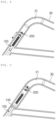
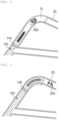
- FIGS. 4 to 9 are views sequentially showing operation processes of the catheter system according to the first embodiment of the present invention.
- the catheter module 100 moves along the blood vessel 30 to the vicinity of a lesion 31 in a state in which the magnetic robot 200 is coupled to the catheter module 100.
- the support balloon 140 of the catheter module 100 expands and is supported on the inner wall of the blood vessel, and accordingly, the flow of blood is blocked.
- the external rotating magnetic field is applied to the driving magnet 220 to generate a rotational force in the magnetic robot 200.
- a fastening protrusion 231 of the second fastening magnet 230 is rotated along the coupling groove 132 of the fastening member 130 by the rotational force, the mechanical coupling between the second fastening magnet 230 and the fastening member 130 is released.
- the magnetic coupling between the first fastening magnet 120 and the second fastening magnet 230 is released.
- the magnetic robot 200 released from the catheter module 100 moves with the driving force generated by the legs 240 while being rotated.
- the magnetic robot 200 performs a drilling process on the lesion 31 by using the drill tip 211.
- the thrombus fragments generated by the drilling process are sucked into the catheter 110 through the internal flow path 131 of the fastening member 130 and the connection flow path 121 of the first fastening magnet 120, by the negative pressure applied to the inner flow path 111 of the catheter 110 from the suction unit.
- the catheter module 100 moves to a point in which the magnetic robot 200 is located.
- the magnetic robot 200 is recombined with the catheter module 100 under the control of the external rotating magnetic field.
- a rotating magnetic field in the reverse direction of the rotating magnetic field applied when the coupling between the magnetic robot 200 and the catheter module 100 is released may be applied.
- the magnetic robot 200 is primarily coupled to the catheter module 100 by the coupling between the coupling protrusion 231 of the second coupling magnet 230 and the coupling groove 131 of the coupling member 130, and secondarily coupled to the catheter module 100 by the magnetic coupling between the first fastening magnet 120 and the second fastening magnet 230.
- the stent deployment balloon 150 expands to deploy the stent 160.
- the blood vessel 30 expands.
- the stent deployment balloon 150 contracts and the catheter module 100 and the magnetic robot 200 are recovered outside the body.
- FIG. 10 is a view showing a catheter system according to a second embodiment of the present invention.
- FIG. 11 is a view showing the catheter module of FIG. 10 .
- FIG. 12 is a sectional view showing the magnetic robot of FIG. 10 .
- FIG. 13 is a sectional view showing the coupling state between the catheter module and the magnetic robot of FIG. 10 .
- FIG. 14 is a view showing the separated state between the catheter module and the magnetic robot of FIG. 10 .
- the catheter module 100 includes a catheter 110, a first fastening magnet 120, and a coupling balloon 170. Although not shown in the drawing, the catheter module 100 may further include the support balloon 140, the stent deployment balloon 150, and the stent 160 that are described in the first embodiment.
- the first fastening magnet 120 is coupled to a tip of the catheter 110.
- the first fastening magnet 120 may have a cone shape in which the diameter is gradually decreased toward the tip.
- the first fastening magnet 120 has a structure in which the N pole and the S pole are arranged facing each other with a central axis thereof interposed therebetween.
- An internal flow path 121 may be formed in the first fastening magnet 120.
- the inner flow path is connected to the inner flow path of the catheter 110. Thrombus fragments may be sucked into the internal flow path of the catheter 110 through the internal flow path of the first fastening magnet 120.
- the coupling balloon 170 is coupled to the catheter 110 at a rear of the first fastening magnet 120.
- the coupling balloon 170 is provided along the circumference of the catheter 110.
- the coupling balloon 170 may expand and contract according to injection of a fluid from the outside.
- the magnetic robot 200 includes a body 210, a second fastening magnet 230, and a leg 240.
- a drill tip 211 is provided at a tip of the body 210.
- the body 210 is formed of a non-magnetic material.
- the body 210 is formed at a rear end thereof with an opening 212, a first fastening groove 213, and a second fastening groove 214.
- the opening 212 is formed at the rear end of the body 210, and the first fastening groove 213 and the second fastening groove 214 are formed inside the body 210.
- the opening 212, the first fastening groove 213, and the second fastening groove 214 are sequentially and inward formed from the rear end of the body 210 and communicate with each other.
- the opening 212 has a diameter larger than the diameter of the catheter 110.
- the first fastening groove 213 has a diameter than the diameter of the opening 212.
- the first fastening groove 213 may have a diameter corresponding to the expanding state of the coupling balloon 170.
- the second fastening groove 214 may have a shape corresponding to the first fastening magnet 120.
- the second fastening magnet 230 is provided along the circumference of the body 210.
- the second fastening magnet 230 has a cylindrical shape and the body is inserted into an inner space thereof.
- the second fastening magnet 230 has the N pole and the S pole disposed to face each other with the body 210 interposed therebetween.
- the second fastening magnet 230 forms a magnetic force together with the first fastening magnet 120 while the catheter module 100 and the magnetic robot 200 are coupled to each other.
- a plurality of legs 240 are provided along the circumference of the body 210 in an area between the drill tip 211 and the second fastening magnet 230 and a rear area of the second fastening magnet 230, and have one end coupled to the body 210.
- the leg 240 is formed of a flexible material having a plate shape.
- the leg 240 is disposed diagonally with respect to a rotation axis of the body 210.
- the leg 240 generates a driving force while being rotated together with the body 210.
- the catheter 110 is inserted into the opening 212 of the body 210 while the coupling balloon 170 contracts.
- the first fastening magnet 120 is located in the second fastening groove 214 and forms a magnetic force together with the second fastening magnet 230.
- the first fastening magnet 120 forms an attractive force with the second fastening magnet 230.
- the coupling balloon 170 is located in the first fastening groove 213, and expands in the first fastening groove 213 by the fluid injected from the outside. Due to the expansion of the coupling balloon 170, the catheter 110 is restricted from being separated from the body 210.
- the catheter module 100 to which the magnetic robot 200 is coupled through the above process deploys the magnetic robot 200 to the vicinity of the lesion.
- the magnetic robot 200 When the magnetic robot 200 enters the vicinity of the lesion 31, the magnetic robot 200 is separated from the catheter module 100. First, the coupling balloon 170 contracts and a rotational force is generated in the magnetic robot 200 by the external rotating magnetic field. The magnetic coupling between the first fastening magnet 120 and the second fastening magnet 230 is released by the rotational force of the magnetic robot 200. The magnetic robot 200 is separated from the catheter module 100 and rotated in the blood vessel to generate a driving force.
- the catheter system according to the present invention may be used to treat constricted and narrowed or blocked vascular diseases due to thrombosis and the like.
Landscapes
- Health & Medical Sciences (AREA)
- Life Sciences & Earth Sciences (AREA)
- Engineering & Computer Science (AREA)
- Surgery (AREA)
- Biomedical Technology (AREA)
- Animal Behavior & Ethology (AREA)
- Heart & Thoracic Surgery (AREA)
- General Health & Medical Sciences (AREA)
- Public Health (AREA)
- Veterinary Medicine (AREA)
- Medical Informatics (AREA)
- Molecular Biology (AREA)
- Nuclear Medicine, Radiotherapy & Molecular Imaging (AREA)
- Robotics (AREA)
- Biophysics (AREA)
- Vascular Medicine (AREA)
- Pulmonology (AREA)
- Anesthesiology (AREA)
- Hematology (AREA)
- Oral & Maxillofacial Surgery (AREA)
- Transplantation (AREA)
- Cardiology (AREA)
- Media Introduction/Drainage Providing Device (AREA)
Claims (6)
- Kathetersystem (10), umfassend:ein Kathetermodul (100), das einen Katheter (110) und einen ersten Befestigungsmagneten (120) aufweist, der mit einer Spitze des Katheters (110) gekoppelt ist;einen magnetischen Roboter (200), der einen zweiten Befestigungsmagneten (230) aufweist, der magnetisch mit dem ersten Befestigungsmagneten (120) gekoppelt ist, und dazu ausgestaltet ist, mit dem Kathetermodul (100) gekoppelt und davon entkoppelt zu werden; undein zylindrisches Befestigungselement (130), das fest mit dem ersten Befestigungsmagneten (120) gekoppelt ist, in einer Innenfläche davon mit einer Kopplungsnut (132) ausgebildet ist und aus einem nichtmagnetischen Material ausgebildet ist,wobei der Katheter (110) darin mit einem inneren Durchflussweg (111) ausgebildet ist und der erste Befestigungsmagnet (120) darin mit einem Verbindungsdurchflussweg (121) ausgebildet ist, der den inneren Durchflussweg (131) mit einem Innenraum des Befestigungselements (130) verbindet, undein Arzneimittel, das über den inneren Durchflussweg (111) zugeführt wird, über den Verbindungsdurchflussweg (121) und den Innenraum des Befestigungselements (130) einer Außenseite des Katheters (110) zugeführt wird.
- Kathetersystem (10) nach Anspruch 1, wobei
der zweite Befestigungsmagnet (230) an einer Außenumfangsfläche davon mit einem Kopplungsvorsprung (231) ausgebildet ist, der an der Kopplungsnut (132) befestigt ist. - Kathetersystem (10) nach Anspruch 2, wobei der magnetische Roboter (200) ferner Folgendes aufweist:einen Körper (210) mit einem vorderen Ende, das mit einer Bohrerspitze (211) versehen ist, und einem hinteren Ende, an das der erste Befestigungsmagnet (120) gekoppelt ist;einen zylindrischen Antriebsmagneten (220), der mit dem Körper (210) zwischen der Bohrerspitze (211) und dem ersten Befestigungsmagneten (120) gekoppelt ist; undeine Mehrzahl von Schenkeln (240), die entlang eines Umfangs des Körpers (210) in einem Bereich zwischen der Bohrerspitze (211) und dem Antriebsmagneten (220) und einem Bereich zwischen dem Antriebsmagneten (220) und dem ersten Befestigungsmagneten (120) vorgesehen sind, aus einem flexiblen Material ausgebildet sind und ein mit einer Außenumfangsfläche des Körpers (210) gekoppeltes Ende aufweisen.
- Kathetersystem nach Anspruch 1,wobei das Kathetermodul (100) ferner einen Kopplungsballon (170) aufweist, der entlang einer Außenumfangsfläche des Katheters (100) vorgesehen ist,der magnetische Roboter (200) ferner einen Körper (210) aufweist, der mit dem zweiten Befestigungsmagneten (230) entlang der Außenumfangsfläche davon gekoppelt ist und von einem hinteren Ende davon nach innen hin nacheinander mit einer Öffnung (212), einer ersten Befestigungsnut (213) und einer zweiten Befestigungsnut (214) ausgebildet ist, undder erste Befestigungsmagnet (120) sich in der zweiten Befestigungsnut (214) befindet und der Kopplungsballon (170) sich in der ersten Befestigungsnut (213) befindet, während das Kathetermodul (100) mit dem magnetischen Roboter (200) gekoppelt ist.
- Kathetersystem (10) nach Anspruch 4, wobei die erste Befestigungsnut (213) einen Durchmesser aufweist, der größer als ein Durchmesser des Katheters (110) ist, und die Öffnung (212) einen Durchmesser aufweist, der größer als der Katheter (110) und kleiner als ein Ausdehnungszustand des Kopplungsballons (170) ist.
- Kathetersystem (10) nach Anspruch 4, wobei der Körper (210) an einem vorderen Ende davon mit einer Bohrerspitze (211) versehen ist und der magnetische Roboter (200) ferner eine Mehrzahl von Schenkeln (240) aufweist, die entlang eines Umfangs des Körpers (210) in einem Bereich zwischen dem zweiten Befestigungsmagneten (230) und der Bohrerspitze (211) und einem Bereich zwischen dem zweiten Befestigungsmagneten (230) und dem hinteren Ende vorgesehen sind, aus einem flexiblen Material ausgebildet sind und ein mit einer Außenumfangsfläche des Körpers (210) gekoppeltes Ende aufweisen.
Applications Claiming Priority (3)
| Application Number | Priority Date | Filing Date | Title |
|---|---|---|---|
| KR20190090845 | 2019-07-26 | ||
| KR1020190103000A KR102348773B1 (ko) | 2019-07-26 | 2019-08-22 | 카테터 시스템 |
| PCT/KR2020/008714 WO2021020751A1 (ko) | 2019-07-26 | 2020-07-03 | 카테터 시스템 |
Publications (3)
| Publication Number | Publication Date |
|---|---|
| EP4005518A1 EP4005518A1 (de) | 2022-06-01 |
| EP4005518A4 EP4005518A4 (de) | 2023-08-23 |
| EP4005518B1 true EP4005518B1 (de) | 2024-09-11 |
Family
ID=74230742
Family Applications (1)
| Application Number | Title | Priority Date | Filing Date |
|---|---|---|---|
| EP20846752.2A Active EP4005518B1 (de) | 2019-07-26 | 2020-07-03 | Kathetersystem |
Country Status (4)
| Country | Link |
|---|---|
| US (1) | US12478402B2 (de) |
| EP (1) | EP4005518B1 (de) |
| CN (1) | CN114173697B (de) |
| WO (1) | WO2021020751A1 (de) |
Families Citing this family (1)
| Publication number | Priority date | Publication date | Assignee | Title |
|---|---|---|---|---|
| WO2023131853A1 (en) * | 2022-01-07 | 2023-07-13 | Multi-Scale Medical Robots Center Limited | Magnetic microrobot |
Family Cites Families (26)
| Publication number | Priority date | Publication date | Assignee | Title |
|---|---|---|---|---|
| CN1235724C (zh) * | 2003-06-24 | 2006-01-11 | 浙江大学 | 一种仿蝌蚪的螺旋式微型机器人 |
| US8287503B2 (en) * | 2006-03-13 | 2012-10-16 | Applied Medical Resources Corporation | Balloon trocar |
| KR101045377B1 (ko) | 2008-07-28 | 2011-06-30 | 전남대학교산학협력단 | 초소형 로봇 및 초소형 로봇의 구동 방법 |
| CN101659054B (zh) * | 2009-09-09 | 2011-04-27 | 大连理工大学 | 一种胶囊机器人及其多楔形效应驱动控制方法 |
| KR20110116968A (ko) * | 2011-01-31 | 2011-10-26 | 서울대학교산학협력단 | 관내를 이동하여 불순물을 제거하는 로봇 |
| CN202020514U (zh) * | 2011-03-08 | 2011-11-02 | 张萍 | 一种输卵管通液器 |
| CN102151162B (zh) * | 2011-04-24 | 2012-07-25 | 广州大学 | 一种清理血栓的磁控血管机器人 |
| KR101981555B1 (ko) * | 2011-10-14 | 2019-08-28 | 인튜어티브 서지컬 오퍼레이션즈 인코포레이티드 | 카테터 시스템 |
| KR101217767B1 (ko) | 2012-07-10 | 2013-01-02 | 전남대학교산학협력단 | 카테터 기반을 가지는 의료 시술용 전자기 구동 수술장치 |
| KR101379859B1 (ko) * | 2012-08-24 | 2014-04-02 | 전남대학교산학협력단 | 혈관치료용 마이크로로봇 및 시스템 |
| KR101510196B1 (ko) * | 2013-10-10 | 2015-04-09 | 한국과학기술연구원 | 신체 내 모듈형 캡슐로봇 동작 제어 시스템 |
| KR101471526B1 (ko) * | 2014-05-07 | 2014-12-12 | 한양대학교 산학협력단 | 의료용 마이크로 로봇 및 이를 갖는 마이크로 로봇 시스템 |
| US10405924B2 (en) * | 2014-05-30 | 2019-09-10 | The Spectranetics Corporation | System and method of ablative cutting and vacuum aspiration through primary orifice and auxiliary side port |
| KR101619931B1 (ko) * | 2014-06-10 | 2016-05-13 | 재단법인대구경북과학기술원 | 캡슐형 마이크로 로봇 및 사용방법 |
| US10994109B2 (en) | 2014-06-27 | 2021-05-04 | Urogen Pharma Ltd. | Connectable catheter |
| KR101659367B1 (ko) * | 2015-10-13 | 2016-09-23 | 재단법인대구경북과학기술원 | 카테터 부착형 마이크로 로봇 |
| JP6196340B2 (ja) * | 2015-02-16 | 2017-09-13 | 大邱慶北科學技術院Daegu Gyeongbuk Institute Of Science And Technology | カテーテルに結合されたマイクロロボット |
| KR101749586B1 (ko) * | 2015-12-24 | 2017-06-21 | 재단법인대구경북과학기술원 | 무선전력전송이 가능한 카테터 기반의 자기 구동 마이크로 로봇 및 이의 제어 방법 |
| JP7237313B2 (ja) * | 2016-07-29 | 2023-03-13 | シャンハイ ワラビー メディカル テクノロジーズ カンパニー インコーポレイテッド | インプラント送達システムおよび方法 |
| KR101831660B1 (ko) * | 2016-10-12 | 2018-02-23 | 원광대학교산학협력단 | 능동형 카테터 장치 및 이의 제어 시스템 |
| CN206587003U (zh) * | 2016-10-31 | 2017-10-27 | 黄冈市妇幼保健院 | 产科止血装置 |
| CN207785324U (zh) * | 2017-06-28 | 2018-08-31 | 常州至善医疗科技有限公司 | 一种胃内球囊系统的新型连接和释放结构 |
| KR101818400B1 (ko) | 2017-08-11 | 2018-01-15 | 한양대학교 산학협력단 | 마그네틱 로봇 시스템 |
| CN107736865A (zh) * | 2017-11-16 | 2018-02-27 | 长沙展朔轩兴信息科技有限公司 | 内窥镜微型胶囊机器人 |
| KR102066327B1 (ko) * | 2017-12-11 | 2020-01-14 | 공주대학교 산학협력단 | 다중 모듈 헬리컬 자기 밀리 로봇 |
| CN109436258B (zh) * | 2018-12-24 | 2023-08-29 | 重庆大学 | 一种基于电磁控制的小微型潜航器 |
-
2020
- 2020-07-03 US US17/630,381 patent/US12478402B2/en active Active
- 2020-07-03 EP EP20846752.2A patent/EP4005518B1/de active Active
- 2020-07-03 WO PCT/KR2020/008714 patent/WO2021020751A1/ko not_active Ceased
- 2020-07-03 CN CN202080054172.0A patent/CN114173697B/zh active Active
Also Published As
| Publication number | Publication date |
|---|---|
| CN114173697B (zh) | 2024-05-28 |
| EP4005518A4 (de) | 2023-08-23 |
| WO2021020751A1 (ko) | 2021-02-04 |
| EP4005518A1 (de) | 2022-06-01 |
| US12478402B2 (en) | 2025-11-25 |
| CN114173697A (zh) | 2022-03-11 |
| US20220280182A1 (en) | 2022-09-08 |
Similar Documents
| Publication | Publication Date | Title |
|---|---|---|
| US11980556B2 (en) | Balloon catheters and methods for use | |
| CN103561686B (zh) | 用于可膨胀球囊支架的经皮输送的临时灌注通道 | |
| EP1587447B1 (de) | Wiederfindungsvorrichtung | |
| US20080208307A1 (en) | Treatment of Vascular Bifurcations | |
| US20070173918A1 (en) | Apparatus and methods for locating an ostium of a vessel | |
| CN110430842B (zh) | 球囊导管和使用方法 | |
| US20130331639A1 (en) | Blood pump with expandable cannula | |
| JP2013533789A (ja) | 血管内注入装置の腔内搬送のための方法及び装置 | |
| EP1357968A2 (de) | System und entsprechende methode für die ablage einer implantierbaren intraluminalen vorrichtung | |
| JPH09639A (ja) | Ptcaによる冠状動脈拡張用器具 | |
| WO2007002423A2 (en) | Balloon catheter | |
| US20240081993A1 (en) | Catheter assembly | |
| US20070288081A1 (en) | Stent delivery system having a stent stopper | |
| WO2024114761A1 (zh) | 管腔开通器械、管腔开通系统及管腔开通方法 | |
| JPH11503641A (ja) | 特に、逆圧を加えることによって心臓の機能を援助する際に、体内の管を一時的に閉じるための装置 | |
| EP4005518B1 (de) | Kathetersystem | |
| CN115038394B (zh) | 导管系统 | |
| KR102348773B1 (ko) | 카테터 시스템 | |
| JPH10286222A (ja) | 内視鏡挿入補助装置 | |
| US11617857B2 (en) | Endovascular catheter with internal balloon | |
| EP2282802A1 (de) | Ballon für ein körperlumen und verwendungsverfahren | |
| JP2019092811A (ja) | バルーンカテーテル | |
| JP2025145386A (ja) | カテーテルデバイス及び回収対象物の回収方法 | |
| JP2006223580A (ja) | バルーンカテーテル |
Legal Events
| Date | Code | Title | Description |
|---|---|---|---|
| STAA | Information on the status of an ep patent application or granted ep patent |
Free format text: STATUS: THE INTERNATIONAL PUBLICATION HAS BEEN MADE |
|
| PUAI | Public reference made under article 153(3) epc to a published international application that has entered the european phase |
Free format text: ORIGINAL CODE: 0009012 |
|
| STAA | Information on the status of an ep patent application or granted ep patent |
Free format text: STATUS: REQUEST FOR EXAMINATION WAS MADE |
|
| 17P | Request for examination filed |
Effective date: 20220221 |
|
| AK | Designated contracting states |
Kind code of ref document: A1 Designated state(s): AL AT BE BG CH CY CZ DE DK EE ES FI FR GB GR HR HU IE IS IT LI LT LU LV MC MK MT NL NO PL PT RO RS SE SI SK SM TR |
|
| DAV | Request for validation of the european patent (deleted) | ||
| DAX | Request for extension of the european patent (deleted) | ||
| REG | Reference to a national code |
Ref legal event code: R079 Ipc: A61B0017320700 Ref country code: DE Ref legal event code: R079 Ref document number: 602020037703 Country of ref document: DE Free format text: PREVIOUS MAIN CLASS: A61B0034000000 Ipc: A61B0017320700 |
|
| A4 | Supplementary search report drawn up and despatched |
Effective date: 20230725 |
|
| RIC1 | Information provided on ipc code assigned before grant |
Ipc: A61B 17/22 20060101ALN20230719BHEP Ipc: A61B 17/00 20060101ALN20230719BHEP Ipc: A61F 2/958 20130101ALI20230719BHEP Ipc: A61M 25/01 20060101ALI20230719BHEP Ipc: A61B 34/00 20160101ALI20230719BHEP Ipc: A61B 34/30 20160101ALI20230719BHEP Ipc: A61B 17/3207 20060101AFI20230719BHEP |
|
| GRAP | Despatch of communication of intention to grant a patent |
Free format text: ORIGINAL CODE: EPIDOSNIGR1 |
|
| STAA | Information on the status of an ep patent application or granted ep patent |
Free format text: STATUS: GRANT OF PATENT IS INTENDED |
|
| RIC1 | Information provided on ipc code assigned before grant |
Ipc: A61B 17/22 20060101ALN20240313BHEP Ipc: A61B 17/00 20060101ALN20240313BHEP Ipc: A61F 2/958 20130101ALI20240313BHEP Ipc: A61M 25/01 20060101ALI20240313BHEP Ipc: A61B 34/00 20160101ALI20240313BHEP Ipc: A61B 34/30 20160101ALI20240313BHEP Ipc: A61B 17/3207 20060101AFI20240313BHEP |
|
| RIC1 | Information provided on ipc code assigned before grant |
Ipc: A61B 17/22 20060101ALN20240327BHEP Ipc: A61B 17/00 20060101ALN20240327BHEP Ipc: A61F 2/958 20130101ALI20240327BHEP Ipc: A61M 25/01 20060101ALI20240327BHEP Ipc: A61B 34/00 20160101ALI20240327BHEP Ipc: A61B 34/30 20160101ALI20240327BHEP Ipc: A61B 17/3207 20060101AFI20240327BHEP |
|
| INTG | Intention to grant announced |
Effective date: 20240415 |
|
| RIN1 | Information on inventor provided before grant (corrected) |
Inventor name: PARK, JIMIN Inventor name: LEE, WONSEO Inventor name: KIM, JONGYUL Inventor name: JANG, GUNHEE |
|
| GRAS | Grant fee paid |
Free format text: ORIGINAL CODE: EPIDOSNIGR3 |
|
| GRAA | (expected) grant |
Free format text: ORIGINAL CODE: 0009210 |
|
| STAA | Information on the status of an ep patent application or granted ep patent |
Free format text: STATUS: THE PATENT HAS BEEN GRANTED |
|
| AK | Designated contracting states |
Kind code of ref document: B1 Designated state(s): AL AT BE BG CH CY CZ DE DK EE ES FI FR GB GR HR HU IE IS IT LI LT LU LV MC MK MT NL NO PL PT RO RS SE SI SK SM TR |
|
| REG | Reference to a national code |
Ref country code: GB Ref legal event code: FG4D |
|
| REG | Reference to a national code |
Ref country code: CH Ref legal event code: EP |
|
| REG | Reference to a national code |
Ref country code: DE Ref legal event code: R096 Ref document number: 602020037703 Country of ref document: DE |
|
| REG | Reference to a national code |
Ref country code: IE Ref legal event code: FG4D |
|
| REG | Reference to a national code |
Ref country code: LT Ref legal event code: MG9D |
|
| PG25 | Lapsed in a contracting state [announced via postgrant information from national office to epo] |
Ref country code: NO Free format text: LAPSE BECAUSE OF FAILURE TO SUBMIT A TRANSLATION OF THE DESCRIPTION OR TO PAY THE FEE WITHIN THE PRESCRIBED TIME-LIMIT Effective date: 20241211 |
|
| REG | Reference to a national code |
Ref country code: NL Ref legal event code: MP Effective date: 20240911 |
|
| PG25 | Lapsed in a contracting state [announced via postgrant information from national office to epo] |
Ref country code: GR Free format text: LAPSE BECAUSE OF FAILURE TO SUBMIT A TRANSLATION OF THE DESCRIPTION OR TO PAY THE FEE WITHIN THE PRESCRIBED TIME-LIMIT Effective date: 20241212 Ref country code: FI Free format text: LAPSE BECAUSE OF FAILURE TO SUBMIT A TRANSLATION OF THE DESCRIPTION OR TO PAY THE FEE WITHIN THE PRESCRIBED TIME-LIMIT Effective date: 20240911 |
|
| PG25 | Lapsed in a contracting state [announced via postgrant information from national office to epo] |
Ref country code: BG Free format text: LAPSE BECAUSE OF FAILURE TO SUBMIT A TRANSLATION OF THE DESCRIPTION OR TO PAY THE FEE WITHIN THE PRESCRIBED TIME-LIMIT Effective date: 20240911 |
|
| PG25 | Lapsed in a contracting state [announced via postgrant information from national office to epo] |
Ref country code: LV Free format text: LAPSE BECAUSE OF FAILURE TO SUBMIT A TRANSLATION OF THE DESCRIPTION OR TO PAY THE FEE WITHIN THE PRESCRIBED TIME-LIMIT Effective date: 20240911 |
|
| PG25 | Lapsed in a contracting state [announced via postgrant information from national office to epo] |
Ref country code: HR Free format text: LAPSE BECAUSE OF FAILURE TO SUBMIT A TRANSLATION OF THE DESCRIPTION OR TO PAY THE FEE WITHIN THE PRESCRIBED TIME-LIMIT Effective date: 20240911 |
|
| PG25 | Lapsed in a contracting state [announced via postgrant information from national office to epo] |
Ref country code: ES Free format text: LAPSE BECAUSE OF FAILURE TO SUBMIT A TRANSLATION OF THE DESCRIPTION OR TO PAY THE FEE WITHIN THE PRESCRIBED TIME-LIMIT Effective date: 20240911 Ref country code: RS Free format text: LAPSE BECAUSE OF FAILURE TO SUBMIT A TRANSLATION OF THE DESCRIPTION OR TO PAY THE FEE WITHIN THE PRESCRIBED TIME-LIMIT Effective date: 20241211 |
|
| PG25 | Lapsed in a contracting state [announced via postgrant information from national office to epo] |
Ref country code: RS Free format text: LAPSE BECAUSE OF FAILURE TO SUBMIT A TRANSLATION OF THE DESCRIPTION OR TO PAY THE FEE WITHIN THE PRESCRIBED TIME-LIMIT Effective date: 20241211 Ref country code: NO Free format text: LAPSE BECAUSE OF FAILURE TO SUBMIT A TRANSLATION OF THE DESCRIPTION OR TO PAY THE FEE WITHIN THE PRESCRIBED TIME-LIMIT Effective date: 20241211 Ref country code: LV Free format text: LAPSE BECAUSE OF FAILURE TO SUBMIT A TRANSLATION OF THE DESCRIPTION OR TO PAY THE FEE WITHIN THE PRESCRIBED TIME-LIMIT Effective date: 20240911 Ref country code: HR Free format text: LAPSE BECAUSE OF FAILURE TO SUBMIT A TRANSLATION OF THE DESCRIPTION OR TO PAY THE FEE WITHIN THE PRESCRIBED TIME-LIMIT Effective date: 20240911 Ref country code: GR Free format text: LAPSE BECAUSE OF FAILURE TO SUBMIT A TRANSLATION OF THE DESCRIPTION OR TO PAY THE FEE WITHIN THE PRESCRIBED TIME-LIMIT Effective date: 20241212 Ref country code: FI Free format text: LAPSE BECAUSE OF FAILURE TO SUBMIT A TRANSLATION OF THE DESCRIPTION OR TO PAY THE FEE WITHIN THE PRESCRIBED TIME-LIMIT Effective date: 20240911 Ref country code: ES Free format text: LAPSE BECAUSE OF FAILURE TO SUBMIT A TRANSLATION OF THE DESCRIPTION OR TO PAY THE FEE WITHIN THE PRESCRIBED TIME-LIMIT Effective date: 20240911 Ref country code: BG Free format text: LAPSE BECAUSE OF FAILURE TO SUBMIT A TRANSLATION OF THE DESCRIPTION OR TO PAY THE FEE WITHIN THE PRESCRIBED TIME-LIMIT Effective date: 20240911 |
|
| REG | Reference to a national code |
Ref country code: AT Ref legal event code: MK05 Ref document number: 1721996 Country of ref document: AT Kind code of ref document: T Effective date: 20240911 |
|
| PG25 | Lapsed in a contracting state [announced via postgrant information from national office to epo] |
Ref country code: NL Free format text: LAPSE BECAUSE OF FAILURE TO SUBMIT A TRANSLATION OF THE DESCRIPTION OR TO PAY THE FEE WITHIN THE PRESCRIBED TIME-LIMIT Effective date: 20240911 |
|
| PG25 | Lapsed in a contracting state [announced via postgrant information from national office to epo] |
Ref country code: IS Free format text: LAPSE BECAUSE OF FAILURE TO SUBMIT A TRANSLATION OF THE DESCRIPTION OR TO PAY THE FEE WITHIN THE PRESCRIBED TIME-LIMIT Effective date: 20250111 Ref country code: PT Free format text: LAPSE BECAUSE OF FAILURE TO SUBMIT A TRANSLATION OF THE DESCRIPTION OR TO PAY THE FEE WITHIN THE PRESCRIBED TIME-LIMIT Effective date: 20250113 |
|
| PG25 | Lapsed in a contracting state [announced via postgrant information from national office to epo] |
Ref country code: RO Free format text: LAPSE BECAUSE OF FAILURE TO SUBMIT A TRANSLATION OF THE DESCRIPTION OR TO PAY THE FEE WITHIN THE PRESCRIBED TIME-LIMIT Effective date: 20240911 Ref country code: SM Free format text: LAPSE BECAUSE OF FAILURE TO SUBMIT A TRANSLATION OF THE DESCRIPTION OR TO PAY THE FEE WITHIN THE PRESCRIBED TIME-LIMIT Effective date: 20240911 |
|
| PG25 | Lapsed in a contracting state [announced via postgrant information from national office to epo] |
Ref country code: EE Free format text: LAPSE BECAUSE OF FAILURE TO SUBMIT A TRANSLATION OF THE DESCRIPTION OR TO PAY THE FEE WITHIN THE PRESCRIBED TIME-LIMIT Effective date: 20240911 Ref country code: AT Free format text: LAPSE BECAUSE OF FAILURE TO SUBMIT A TRANSLATION OF THE DESCRIPTION OR TO PAY THE FEE WITHIN THE PRESCRIBED TIME-LIMIT Effective date: 20240911 |
|
| PG25 | Lapsed in a contracting state [announced via postgrant information from national office to epo] |
Ref country code: PL Free format text: LAPSE BECAUSE OF FAILURE TO SUBMIT A TRANSLATION OF THE DESCRIPTION OR TO PAY THE FEE WITHIN THE PRESCRIBED TIME-LIMIT Effective date: 20240911 Ref country code: CZ Free format text: LAPSE BECAUSE OF FAILURE TO SUBMIT A TRANSLATION OF THE DESCRIPTION OR TO PAY THE FEE WITHIN THE PRESCRIBED TIME-LIMIT Effective date: 20240911 |
|
| PG25 | Lapsed in a contracting state [announced via postgrant information from national office to epo] |
Ref country code: IT Free format text: LAPSE BECAUSE OF FAILURE TO SUBMIT A TRANSLATION OF THE DESCRIPTION OR TO PAY THE FEE WITHIN THE PRESCRIBED TIME-LIMIT Effective date: 20240911 Ref country code: SK Free format text: LAPSE BECAUSE OF FAILURE TO SUBMIT A TRANSLATION OF THE DESCRIPTION OR TO PAY THE FEE WITHIN THE PRESCRIBED TIME-LIMIT Effective date: 20240911 |
|
| REG | Reference to a national code |
Ref country code: DE Ref legal event code: R097 Ref document number: 602020037703 Country of ref document: DE |
|
| PG25 | Lapsed in a contracting state [announced via postgrant information from national office to epo] |
Ref country code: DK Free format text: LAPSE BECAUSE OF FAILURE TO SUBMIT A TRANSLATION OF THE DESCRIPTION OR TO PAY THE FEE WITHIN THE PRESCRIBED TIME-LIMIT Effective date: 20240911 |
|
| PLBE | No opposition filed within time limit |
Free format text: ORIGINAL CODE: 0009261 |
|
| STAA | Information on the status of an ep patent application or granted ep patent |
Free format text: STATUS: NO OPPOSITION FILED WITHIN TIME LIMIT |
|
| 26N | No opposition filed |
Effective date: 20250612 |
|
| PG25 | Lapsed in a contracting state [announced via postgrant information from national office to epo] |
Ref country code: SE Free format text: LAPSE BECAUSE OF FAILURE TO SUBMIT A TRANSLATION OF THE DESCRIPTION OR TO PAY THE FEE WITHIN THE PRESCRIBED TIME-LIMIT Effective date: 20240911 |
|
| PGFP | Annual fee paid to national office [announced via postgrant information from national office to epo] |
Ref country code: DE Payment date: 20250707 Year of fee payment: 6 |
|
| PGFP | Annual fee paid to national office [announced via postgrant information from national office to epo] |
Ref country code: GB Payment date: 20250707 Year of fee payment: 6 |
|
| PGFP | Annual fee paid to national office [announced via postgrant information from national office to epo] |
Ref country code: FR Payment date: 20250715 Year of fee payment: 6 |
|
| PGFP | Annual fee paid to national office [announced via postgrant information from national office to epo] |
Ref country code: CH Payment date: 20250801 Year of fee payment: 6 |
|
| PG25 | Lapsed in a contracting state [announced via postgrant information from national office to epo] |
Ref country code: LU Free format text: LAPSE BECAUSE OF NON-PAYMENT OF DUE FEES Effective date: 20250703 |
|
| REG | Reference to a national code |
Ref country code: BE Ref legal event code: MM Effective date: 20250731 |
|
| PG25 | Lapsed in a contracting state [announced via postgrant information from national office to epo] |
Ref country code: BE Free format text: LAPSE BECAUSE OF NON-PAYMENT OF DUE FEES Effective date: 20250731 |