EP4005697A1 - Vorrichtung und verfahren zur temperaturerfassung in einer seitenwandplatte einer giesskokille - Google Patents
Vorrichtung und verfahren zur temperaturerfassung in einer seitenwandplatte einer giesskokille Download PDFInfo
- Publication number
- EP4005697A1 EP4005697A1 EP20210150.7A EP20210150A EP4005697A1 EP 4005697 A1 EP4005697 A1 EP 4005697A1 EP 20210150 A EP20210150 A EP 20210150A EP 4005697 A1 EP4005697 A1 EP 4005697A1
- Authority
- EP
- European Patent Office
- Prior art keywords
- built
- measuring
- section
- measuring device
- casting mold
- Prior art date
- Legal status (The legal status is an assumption and is not a legal conclusion. Google has not performed a legal analysis and makes no representation as to the accuracy of the status listed.)
- Granted
Links
Images

Classifications
-
- B—PERFORMING OPERATIONS; TRANSPORTING
- B22—CASTING; POWDER METALLURGY
- B22D—CASTING OF METALS; CASTING OF OTHER SUBSTANCES BY THE SAME PROCESSES OR DEVICES
- B22D11/00—Continuous casting of metals, i.e. casting in indefinite lengths
- B22D11/04—Continuous casting of metals, i.e. casting in indefinite lengths into open-ended moulds
-
- B—PERFORMING OPERATIONS; TRANSPORTING
- B22—CASTING; POWDER METALLURGY
- B22D—CASTING OF METALS; CASTING OF OTHER SUBSTANCES BY THE SAME PROCESSES OR DEVICES
- B22D11/00—Continuous casting of metals, i.e. casting in indefinite lengths
- B22D11/04—Continuous casting of metals, i.e. casting in indefinite lengths into open-ended moulds
- B22D11/057—Manufacturing or calibrating the moulds
-
- B—PERFORMING OPERATIONS; TRANSPORTING
- B22—CASTING; POWDER METALLURGY
- B22D—CASTING OF METALS; CASTING OF OTHER SUBSTANCES BY THE SAME PROCESSES OR DEVICES
- B22D11/00—Continuous casting of metals, i.e. casting in indefinite lengths
- B22D11/16—Controlling or regulating processes or operations
-
- B—PERFORMING OPERATIONS; TRANSPORTING
- B22—CASTING; POWDER METALLURGY
- B22D—CASTING OF METALS; CASTING OF OTHER SUBSTANCES BY THE SAME PROCESSES OR DEVICES
- B22D11/00—Continuous casting of metals, i.e. casting in indefinite lengths
- B22D11/16—Controlling or regulating processes or operations
- B22D11/18—Controlling or regulating processes or operations for pouring
- B22D11/181—Controlling or regulating processes or operations for pouring responsive to molten metal level or slag level
- B22D11/182—Controlling or regulating processes or operations for pouring responsive to molten metal level or slag level by measuring temperature
-
- G—PHYSICS
- G01—MEASURING; TESTING
- G01K—MEASURING TEMPERATURE; MEASURING QUANTITY OF HEAT; THERMALLY-SENSITIVE ELEMENTS NOT OTHERWISE PROVIDED FOR
- G01K11/00—Measuring temperature based upon physical or chemical changes not covered by groups G01K3/00, G01K5/00, G01K7/00 or G01K9/00
- G01K11/32—Measuring temperature based upon physical or chemical changes not covered by groups G01K3/00, G01K5/00, G01K7/00 or G01K9/00 using changes in transmittance, scattering or luminescence in optical fibres
- G01K11/3206—Measuring temperature based upon physical or chemical changes not covered by groups G01K3/00, G01K5/00, G01K7/00 or G01K9/00 using changes in transmittance, scattering or luminescence in optical fibres at discrete locations in the fibre, e.g. using Bragg scattering
Definitions
- the invention relates to a measuring device for measuring the temperature in a side wall plate of a casting mold and a casting mold with such a measuring device.
- Casting molds are used in the continuous casting of metallic strands.
- molten metal is poured into a mold, which solidifies on the side walls of the mold to form a metallic strand with an already solidified strand shell and a core that is still liquid.
- the partially solidified strand is drawn out of the mold.
- the drawing off of the strand is coordinated with the casting in such a way that a meniscus, ie a liquid level in the mold, remains essentially constant.
- the strand emerging from the mold must already have a sufficiently thick strand shell, since otherwise there is a risk of the shell breaking through. Furthermore, the strand shell must not stick to the mold walls. Sufficient cooling and a casting speed adapted to the mold are particularly important for a stable casting process.
- a temperature distribution in the mold is monitored in particular. For this purpose, for example, the temperatures of a side wall plate of the mold that is in contact with the partially solidified strand in the mold are recorded. The temperatures are recorded, for example, at various points on the side wall panel in order to determine a two-dimensional temperature distribution in the vertical and horizontal directions.
- EP 3 424 614 A1 discloses an installation of a fiber optic temperature sensor in a mold and a mold with multiple fiber optic temperature sensors.
- WO 2017/186702 A2 discloses a method for inserting an optical fiber into a side wall of a continuous casting mold. In this case, a cross-sectional area of a corresponding auxiliary recess is reduced by introducing an additional element in order to create a recess with a smaller cross-sectional area for the optical waveguide.
- the object of the invention is to improve the temperature detection in a side wall plate of a casting mold.
- the object is achieved according to the invention by a measuring device with the features of claim 1, a method for producing such a measuring device with the features of claim 8, a casting mold with the features of claim 9 and a method for operating such a casting mold with the features of claim 15 solved.
- the measuring section of the fiber optic sensor has an optical waveguide with at least one fiber Bragg grating in a predetermined distance from a reference point is arranged on the fixture
- a measuring device enables the temperature to be recorded in a side wall plate of a casting mold using a fiber-optic sensor with at least one fiber Bragg grating.
- a fiber optic sensor is suitable for temperature measurement in a side wall plate of a casting mold, among other things, because temperature measurement with the fiber optic sensor is insensitive to interference from electromagnetic fields, in contrast to temperature measurement with thermocouples, for example.
- Disruptive electromagnetic fields can be caused, for example, by an electromagnetic stirrer (mold electromagnetic stirrer, MEMS for short) or an electromagnetic brake (EMB for short).
- Electromagnetic stirrers and brakes are increasingly being used for casting molds in order to act on metallic melts in the casting molds.
- the mounting part enables the fiber optic sensor to be easily installed in a side wall plate of a casting mold and the fiber optic sensor to be removed from the side wall plate by inserting the mounting part into a corresponding plate recess in the side wall plate or pulling it out of the plate recess.
- the fiber optic sensor is particularly reusable. This is particularly advantageous because the lifetime of a fiber optic sensor is typically longer than the lifetime of a mold sidewall plate. This is because a side wall plate of this type has to be remilled regularly on the inner hot side in order to eliminate signs of wear, and it therefore has to be scrapped after a certain period of use when its thickness is no longer sufficient for further use.
- the fitting further protects the fiber optic sensor advantageous against mechanical loads during installation and removal.
- the fiber-optic sensor can have an optical waveguide with a plurality of fiber Bragg gratings distributed along its length.
- temperatures can advantageously be detected at a plurality of locations in the side wall panel at the same time, for example along a vertical or horizontal extent of the side wall panel.
- the fiber Bragg gratings are each arranged at a predetermined distance from a reference point on the built-in part, the temperatures are recorded at defined measurement positions that are given by the distances of the fiber Bragg gratings from the reference point.
- the reference point is, for example, a point on a contact surface of the built-in part, with which the built-in part rests against a support surface of the side wall panel.
- the measuring device has a sealing element which is arranged on an outer surface of the built-in part.
- the sealing element can advantageously be used to seal an installation point for the built-in part in the side wall plate to protect the fiber-optic sensor from moisture and dirt.
- the built-in part has a guide channel in which the part of the measuring section of the fiber-optic sensor running inside the built-in part is arranged. This stabilizes and positions the sensing portion of the fiber optic sensor within the fixture.
- the measuring section of the fiber-optic sensor is glued to the built-in part using an adhesive.
- the adhesive fills, for example, a gap between a guide channel wall of the guide channel and the measurement section of the fiber optic sensor completely.
- the measuring section has a protective cannula, in which the optical waveguide of the measuring section is arranged and which is glued to the built-in part.
- the bonding with the built-in part also stabilizes the measuring section of the fiber optic sensor within the built-in part.
- the built-in part is made of plastic or metal. Manufacturing the built-in part from plastic advantageously enables simple and inexpensive production of the built-in part. Manufacturing the built-in part from metal advantageously enables a particularly stable design of the built-in part.
- part of the feed section runs inside the built-in part and the feed section and the measuring section are connected to one another inside the built-in part, i.e. the connection point of the feed section and the measuring section is arranged inside the built-in part.
- this connection point in particular is advantageously protected and stabilized by the built-in part.
- the part of the feed section running inside the built-in part is also preferably arranged in the guide channel and glued to the built-in part analogously to the measuring section.
- the fiber optic sensor is curved inside the built-in part. In this way, in particular, a deflection of the fiber-optic sensor within the built-in part can be achieved.
- the built-in part is produced with a 3D print or as a turned part, a milled part or a welded part made of plastic or metal.
- a casting mold according to the invention comprises at least one measuring device according to the invention and at least one side wall plate with at least one plate recess, in which the built-in part of a measuring device is arranged, and a measuring channel connected to the plate recess, in which a part of the measuring section of the fiber-optic sensor of the measuring device running outside the built-in part is arranged is.
- a casting mold according to the invention enables the installation and removal of at least one fiber-optic sensor in or from a side wall plate of the casting mold and thus in particular the reusability of the fiber-optic sensor with the advantages already mentioned above.
- the built-in part of the measuring device is placed in the panel recess and the measuring section of the fiber optic sensor is placed in the measuring channel of the side wall panel.
- the built-in part of the measuring device is guided out of the plate recess and the measuring section of the fiber optic sensor is guided out of the measuring channel in the side wall plate.
- the built-in part of a measuring device has a contact surface having the reference point, and the plate recess in which the built-in part is arranged has a support surface against which the contact surface rests.
- a further embodiment of the casting mold according to the invention has a sealing element already mentioned above, which is arranged between an outer surface of the built-in part of a measuring device and a recess wall of the plate recess in which the built-in part is arranged, in the vicinity of the connection of the plate recess to the measuring channel connected to the plate recess is.
- the sealing element advantageously protects the fiber-optic sensor of the measuring device from moisture and dirt, which could otherwise penetrate through the plate recess.
- the built-in part has a nose-like sealing section, from which the measuring section of a fiber-optic sensor is led out and which is inserted into a corresponding sealing area of the plate recess, which is connected to the measuring channel and in which the sealing element is arranged .
- the sealing element can be designed as an O-ring running annularly around the sealing section of the built-in part or as a flat seal arranged on the sealing section. This achieves an expedient arrangement and design of the sealing element.
- the nose-like sealing section can facilitate the positioning of the built-in part in the panel recess of the side wall panel.
- the casting mold has at least one feed channel in which part of at least one feed section of the fiber-optic sensor of a measuring device is arranged.
- the supply channel runs in a side wall plate of the casting mold and/or in a side wall plate supporting plate Casting mold support plate.
- the feed channel advantageously allows the feed section of at least one fiber optic sensor to be guided and protected, for example by covering the feed channel.
- the feed sections of fiber-optic sensors of several measuring devices according to the invention can be arranged in a feed channel, the measuring sections of which are arranged in different measuring channels in the side wall panel.
- the casting mold has at least one flange in which one end of at least one feed section is arranged or through which one end of at least one feed section is guided and which is attached to a side wall plate of the casting mold and/or to a support plate supporting a side wall plate the casting mold is arranged.
- the flange has, for example, two detachably connected flange parts.
- the end of at least one feed section can be protected from moisture and dirt and from mechanical influences by the flange.
- an optical interface can be arranged in or on the flange, via which at least one fiber-optic sensor can be connected to an optical interrogator that is set up to evaluate the measurement signals of the fiber-optic sensor.
- the design of the flange with two flange parts that are detachably connected to one another makes it possible in particular to open the flange for connecting an optical interrogator to at least one fiber-optic sensor, for example via a connecting optical waveguide.
- a temperature is recorded with a measuring device at at least one measuring position in the side wall plate.
- FIG 1 to FIG 4 show an exemplary embodiment of a casting mold 1 according to the invention, with only components of the casting mold 1 relevant to the invention being shown.
- Components of the casting mold 1 shown in the figures are a side wall plate 3, a support plate 5 and a number of measuring devices 7 according to the invention, which are each set up for measuring the temperature in the side wall plate 3.
- the side wall plate 3 When the casting mold 1 is in operation, the side wall plate 3 is in contact with a partially solidified metallic strand which is formed from molten metal poured into the casting mold 1 .
- the side wall plate 3 is a copper plate.
- the support plate 5 which is also referred to as a back-up plate, rests against a surface of the side wall plate 3 facing away from the metallic strand and serves to support and cool the side wall plate 3.
- Each measuring device 7 comprises a fiber-optic sensor 9 and a mounting part 11.
- the fiber-optic sensor 9 comprises a measuring section 13, which is set up for temperature detection, and a feed section 15, which is used to feed electromagnetic radiation to the measuring section 13 and to derive electromagnetic radiation from the measuring section 13 is set up.
- the measuring section 13 and the feed section 15 are within the mounting part 11 in below with reference to FIG Figures 3 and 4 guided in a manner described in more detail and connected to one another.
- FIG 1 shows part of a side wall plate 3, part of a support plate 5 and built-in parts 11 and feed sections 15 of measuring devices 7 of the casting mold 1 in a perspective view.
- the side wall panel 3 has a plurality of panel recesses 23, in each of which the built-in part 11 of a measuring device 7 is arranged.
- the plate recesses 23 are openings in an upper side 24 of the side wall plate 3 which are connected to one another by a channel-like supply channel 25 running horizontally in the upper side 24 of the side wall plate 3 .
- the feed channel 25 the feed sections 15 of fiber optic sensors 9 are each guided from a flange 27 arranged laterally on the side wall plate 3 to a built-in part 11 .
- the feed sections 15 are each optical waveguides, which each have an elastic protective sheathing made of plastic, for example. Ends of the feed sections 15 are arranged in the flange 27 . These ends of the feed sections 15 are connected to an optical interface arranged in or on the flange 27 Connecting optical waveguide 29 is connected to an optical interrogator (not shown), which is set up to evaluate the measurement signals from the fiber-optic sensors 9 .
- the connecting light waveguides 29 are connected to the optical interface, for example via optical connectors.
- the flange 27 consists of two detachably connected flange parts 27.1, 27.2, so that the flange can be opened to connect the connecting light waveguides 29 and/or the feed sections 15 to the optical interface.
- the feed channel 25 is closed by a cover plate 31 to protect the fiber optic sensors 9 from moisture and dirt.
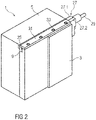
- FIG 2 shows a perspective representation of a part of the side wall plate 3, the support plate 5 and the cover plate 31 of the casting mold 1.
- the cover plate 31 is detachably connected to the upper side 24 of the side wall plate 3 by screw elements 33.
- the first area represents the side wall panel 3 in its new condition
- the second area represents the side wall panel 3 in the worn condition in which the side wall panel 3 needs to be replaced.
- the thickness of the side wall panel 3 is, for example, about 40 mm when new and about 25 mm when worn.
- the side wall panel 3 has, for example, a height in the range from about 700 mm to 1200 mm and a width in the range from about 60 mm to 3500 mm.
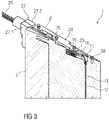
- FIG 3 shows the side wall plate 3, support plate 5 and measuring devices 7 of the casting mold 1 in a perspective sectional view.
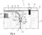
- FIG 4 shows a sectional view of the casting mold 1 in the area of the built-in part 11 of a measuring device 7.
- Each plate recess 23 in the side wall plate 3 is connected to a measuring channel 17 in the side wall plate 3 which is a vertically running bore in the side wall plate 3 .
- the measuring section 13 of a fiber optic sensor 9 runs in the measuring channel 17 and is guided out of the built-in part 11 which is arranged in the plate recess 23 connected to the measuring channel 17 .
- the measuring channel 17 has a diameter in the range of approximately 1 mm to 4 mm, for example.
- the measuring section 13 of a fiber optic sensor 9 has an optical waveguide with at least one fiber Bragg grating.
- the optical waveguide is arranged in a protective cannula.
- the protective cannula is made of stainless steel, for example, and has an outer diameter of about 1 mm to 3.8 mm, for example.
- the built-in part 11 of a measuring device 7 has a guide channel 19 in which a feed section 15.1 of the feed section 15 and a measuring end section 13.1 of the measuring section 13 of the fiber optic sensor 9 of the measuring device 7 are arranged and connected to one another.
- the feed section 15.1 and the measuring end section 13.1 of the fiber optic sensor 9 are glued to the built-in part 11, for example with an adhesive.
- the adhesive fills, for example, a gap between a guide channel wall of the guide channel 19 and the feed section 15.1 and the measuring end section 13.1 of the fiber optic sensor 9 completely.
- the built-in part 11 of a measuring device 7 has a nose-like sealing section 11.1, from which the measuring section 13 of the fiber-optic sensor 9 is led out.
- the built-in part 11 is inserted in the plate recess 23 used that a bearing surface 11.2 of the built-in part 11 contacts a support surface 23.2 of the plate recess 23 and the sealing section 11.1 is inserted into a corresponding sealing area 23.1 of the plate recess 23, which is connected to the measuring channel 17.
- the bearing surface 11.2 represents a reference point P, relative to which the at least one fiber Bragg grating of the fiber-optic sensor 9 is arranged at a predetermined distance.
- a sealing element 21 is arranged on the sealing section 11.1, which seals an intermediate space between the outer surface of the sealing section 11.1 and the wall of the sealing area 23.1.
- the sealing element 21 is an O-ring, which is arranged in an annular groove 22 in the sealing section 11.1.
- the built-in part 11 of a measuring device 7 is produced with a 3D print or as a turned part, a milled part or a welded part made of plastic or metal. Apart from the sealing section 11.1, the built-in part 11 is essentially cuboid with a height and width of, for example, approximately 30 mm each and a depth of, for example, approximately 18 mm.
- the feed channel 25 can be arranged entirely or partially in the support plate 5 .
- the sealing element 21 of a measuring device 7 can be designed as a different seal, for example as a flat seal, instead of as an O-ring.
- the measuring section 13 of a measuring device 7 through the entire Run the guide channel 19 of the built-in part 11 and be connected to the feed section 15 outside of the built-in part 11 .
- the supply section 15 of a measuring device 7 can have two supply sections, with a first supply section running completely outside of the built-in part 11 and having an elastic protective sheathing made of plastic, and a second supply section connecting the first supply section to the measuring section 13, running partially inside the built-in part 11 and one rigid, for example metallic protective coating.
- the ends of the feed sections 15 can be guided through the flange 27 and connected to the connecting optical waveguides 29 outside of the flange 27 .
- the cover plate 31 can be connected to the side wall plate 23 in a manner other than by screw elements 33, for example by gluing.
Landscapes
- Engineering & Computer Science (AREA)
- Mechanical Engineering (AREA)
- Manufacturing & Machinery (AREA)
- Physics & Mathematics (AREA)
- General Physics & Mathematics (AREA)
- Measuring Temperature Or Quantity Of Heat (AREA)
Abstract
Description
- Die Erfindung betrifft eine Messvorrichtung zur Temperaturerfassung in einer Seitenwandplatte einer Gießkokille und eine Gießkokille mit einer derartigen Messvorrichtung.
- Gießkokillen werden beim Stranggießen metallischer Stränge verwendet. Beim Stranggießen wird in eine Kokille eine Metallschmelze gegossen, die an Seitenwänden der Kokille zu einem metallischen Strang mit einer bereits erstarrten Strangschale und einem noch flüssigen Kern erstarrt. Synchron mit dem Gießen der Schmelze in die Kokille wird der teilerstarrte Strang aus der Kokille abgezogen. Das Abziehen des Strangs wird mit dem Gießen derart koordiniert, dass ein Gießspiegel, das heißt ein Flüssigkeitsstand in der Kokille, im Wesentlichen konstant bleibt.
- Der aus der Kokille austretende Strang muss eine bereits hinreichend dicke Strangschale aufweisen, da anderenfalls die Gefahr eines Schalendurchbruchs besteht. Weiterhin darf die Strangschale nicht an den Kokillenwänden anhaften. Entscheidend für einen stabilen Gießprozess sind insbesondere eine ausreichende Kühlung und eine der Kokille angepasste Gießgeschwindigkeit. Um den Gießprozess zu steuern, wird insbesondere eine Temperaturverteilung in der Kokille überwacht. Dazu werden beispielsweise Temperaturen einer Seitenwandplatte der Kokille erfasst, die in Kontakt dem teilerstarrten Strang in der Kokille steht. Die Temperaturen werden beispielsweise an verschiedenen Stellen der Seitenwandplatte erfasst, um eine zweidimensionale Temperaturverteilung in vertikaler und horizontaler Richtung zu ermitteln.
-
EP 3 424 614 A1 offenbart einen Einbau eines faseroptischen Temperatursensors in eine Kokille und eine Kokille mit mehreren faseroptischen Temperatursensoren. -
WO 2017/186702 A2 offenbart ein Verfahren zum Einbringen eines Lichtwellenleiters in eine Seitenwand einer Stranggießkokille. Dabei wird eine Querschnittsfläche einer entsprechenden Hilfsausnehmung durch Einbringen eines Zusatzelements verkleinert, um für den Lichtwellenleiter eine Ausnehmung mit kleinerer Querschnittsfläche zu schaffen. - Der Erfindung liegt die Aufgabe zugrunde, die Temperaturerfassung in einer Seitenwandplatte einer Gießkokille zu verbessern.
- Die Aufgabe wird erfindungsgemäß durch eine Messvorrichtung mit den Merkmalen des Anspruchs 1, ein Verfahren zur Herstellung einer derartigen Messvorrichtung mit den Merkmalen des Anspruchs 8, eine Gießkokille mit den Merkmalen des Anspruchs 9 und ein Verfahren zum Betreiben einer derartigen Gießkokille mit den Merkmalen des Anspruchs 15 gelöst.
- Vorteilhafte Ausgestaltungen der Erfindung sind Gegenstand der Unteransprüche.
- Eine erfindungsgemäße Messvorrichtung zur Temperaturerfassung in einer Seitenwandplatte einer Gießkokille umfasst einen faseroptischen Sensor mit einem Messabschnitt, der zur Temperaturerfassung eingerichtet ist, und einem Zuleitabschnitt, der zum Zuleiten elektromagnetischer Strahlung zu dem Messabschnitt und Ableiten elektromagnetischer Strahlung aus dem Messabschnitt eingerichtet ist, und einen Einbauteil, innerhalb dessen ein Teil des Messabschnitts verläuft. Der Messabschnitt des faseroptischen Sensors weist einen Lichtwellenleiter mit wenigstens einem Faser-Bragg-Gitter auf, das in einem vorgegebenen Abstand von einem Referenzpunkt an dem Einbauteil angeordnet ist
- Eine erfindungsgemäße Messvorrichtung ermöglicht die Temperaturerfassung in einer Seitenwandplatte einer Gießkokille durch einen faseroptischen Sensor mit wenigstens einem Faser-Bragg-Gitter. Ein derartiger faseroptischer Sensor eignet sich zur Temperaturmessung in einer Seitenwandplatte einer Gießkokille unter anderem, weil die Temperaturmessung mit dem faseroptischen Sensor unempfindlich gegenüber Störungen durch elektromagnetische Felder ist, im Unterschied beispielsweise zur Temperaturmessung mit Thermoelementen. Störende elektromagnetische Felder können beispielsweise von einem elektromagnetischen Rührer (engl. mold electromagnetic stirrer, abgekürzt MEMS) oder einer elektromagnetischen Bremse (engl. electromagnetic brake, abgekürzt EMB) verursacht werden. Elektromagnetische Rührer und Bremsen werden für Gießkokillen immer häufiger eingesetzt, um auf metallische Schmelzen in den Gießkokillen einzuwirken.
- Der Einbauteil ermöglicht einen einfachen Einbau des faseroptischen Sensors in eine Seitenwandplatte einer Gießkokille sowie den Ausbau des faseroptischen Sensors aus der Seitenwandplatte, indem der Einbauteil in eine entsprechende Plattenausnehmung in der Seitenwandplatte eingesetzt wird beziehungsweise aus der Plattenausnehmung herausgezogen wird. Dadurch ist der faseroptische Sensor insbesondere wiederverwendbar. Dies ist besonders vorteilhaft, weil die Lebensdauer eines faseroptischen Sensors in der Regel höher ist als die Lebensdauer einer Seitenwandplatte einer Gießkokille. Eine derartige Seitenwandplatte muss nämlich regelmäßig auf der innenliegenden Heißseite nachgefräst werden, um Verschleißerscheinungen zu beseitigen, und muss daher nach einer gewissen Einsatzdauer verschrottet werden, wenn ihre Dicke für eine weitere Verwendung nicht mehr ausreicht. Der Einbauteil schützt den faseroptischen Sensor ferner vorteilhaft vor mechanischen Belastungen bei dessen Ein- und Ausbau.
- Insbesondere kann der faseroptische Sensor einen Lichtwellenleiter mit mehreren entlang seiner Länge verteilten Faser-Bragg-Gittern aufweisen. Dadurch können vorteilhaft gleichzeitig Temperaturen an mehreren Orten in der Seitenwandplatte erfasst werden, beispielsweise entlang einer vertikalen oder horizontalen Ausdehnung der Seitenwandplatte. Da erfindungsgemäß die Faser-Bragg-Gitter jeweils in einem vorgegebenen Abstand von einem Referenzpunkt an dem Einbauteil angeordnet sind, werden die Temperaturen dabei an definierten Messpositionen erfasst, die durch die Abstände der Faser-Bragg-Gitter von dem Referenzpunkt gegeben sind. Der Referenzpunkt ist beispielsweise ein Punkt einer Anlagefläche des Einbauteils, mit der der Einbauteil an einer Stützfläche der Seitenwandplatte anliegt.
- Bei einer Ausgestaltung der erfindungsgemäßen Messvorrichtung weist die Messvorrichtung ein Dichtelement auf, das an einer Außenoberfläche des Einbauteils angeordnet ist. Durch das Dichtelement kann vorteilhaft eine Einbaustelle für den Einbauteil in der Seitenwandplatte zum Schutz des faseroptischen Sensors vor Feuchtigkeit und Schmutz abgedichtet werden.
- Bei einer weiteren Ausgestaltung der erfindungsgemäßen Messvorrichtung weist der Einbauteil einen Führungskanal auf, in dem der innerhalb des Einbauteils verlaufende Teil des Messabschnitts des faseroptischen Sensors angeordnet ist. Dadurch wird der Messabschnitt des faseroptischen Sensors innerhalb des Einbauteils stabilisiert und positioniert.
- Bei einer weiteren Ausgestaltung der erfindungsgemäßen Messvorrichtung ist der Messabschnitt des faseroptischen Sensors mit dem Einbauteil durch einen Klebstoff verklebt. Der Klebstoff füllt beispielsweise einen Zwischenraum zwischen einer Führungskanalwandung des Führungskanals und dem Messabschnitt des faseroptischen Sensors vollständig aus. Genauer gesagt weist der Messabschnitt eine Schutzkanüle auf, in der der Lichtwellenleiter des Messabschnitts angeordnet ist und die mit dem Einbauteil verklebt ist. Die Verklebung mit dem Einbauteil stabilisiert den Messabschnitt des faseroptischen Sensors ebenfalls innerhalb des Einbauteils. Durch ein Ausfüllen des Zwischenraums zwischen einer Führungskanalwandung des Führungskanals und dem Messabschnitt des faseroptischen Sensors wird ferner vorteilhaft eine Dichtheit des Einbauteils gegen ein Eindringen von Feuchtigkeit und Schmutz erreicht.
- Bei einer weiteren Ausgestaltung der erfindungsgemäßen Messvorrichtung ist der Einbauteil aus Kunststoff oder Metall gefertigt. Die Fertigung des Einbauteils aus Kunststoff ermöglicht vorteilhaft eine einfache und kostengünstige Herstellung des Einbauteils. Die Fertigung des Einbauteils aus Metall ermöglicht vorteilhaft eine besonders stabile Ausführung des Einbauteils.
- Bei einer weiteren Ausgestaltung der erfindungsgemäßen Messvorrichtung verläuft ein Teil des Zuleitabschnitts innerhalb des Einbauteils und der Zuleitabschnitt und der Messabschnitt sind innerhalb des Einbauteils miteinander verbunden, das heißt die Verbindungsstelle des Zuleitabschnitts und des Messabschnitts ist innerhalb des Einbauteils angeordnet. Dadurch wird insbesondere diese Verbindungsstelle vorteilhaft durch den Einbauteil geschützt und stabilisiert. Auch der innerhalb des Einbauteils verlaufende Teil des Zuleitabschnitts ist dabei vorzugsweise in dem Führungskanal angeordnet und analog zu dem Messabschnitt mit dem Einbauteil verklebt.
- Bei einer weiteren Ausgestaltung der erfindungsgemäßen Messvorrichtung verläuft der faseroptische Sensor innerhalb des Einbauteils gekrümmt. Dadurch kann insbesondere eine Umlenkung des faseroptischen Sensors innerhalb des Einbauteils erreicht werden.
- Bei dem erfindungsgemäßen Verfahren zur Herstellung einer erfindungsgemäßen Messvorrichtung wird der Einbauteil mit einem 3D-Druck oder als ein Drehteil, ein Frästeil oder ein Schweißteil aus Kunststoff oder Metall gefertigt.
- Eine erfindungsgemäße Gießkokille umfasst wenigstens eine erfindungsgemäße Messvorrichtung und wenigstens eine Seitenwandplatte mit wenigstens einer Plattenausnehmung, in der der Einbauteil einer Messvorrichtung angeordnet ist, und einem mit der Plattenausnehmung verbundenen Messkanal, in dem ein außerhalb des Einbauteils verlaufender Teil des Messabschnitts des faseroptischen Sensors der Messvorrichtung angeordnet ist.
- Eine erfindungsgemäße Gießkokille ermöglicht den Einbau und Ausbau wenigstens eines faseroptischen Sensors in eine beziehungsweise aus einer Seitenwandplatte der Gießkokille und damit insbesondere die Wiederverwendbarkeit des faseroptischen Sensors mit den oben bereits genannten Vorteilen. Beim Einbau werden der Einbauteil der Messvorrichtung in die Plattenausnehmung und der Messabschnitt des faseroptischen Sensors in den Messkanal der Seitenwandplatte eingebracht. Beim Ausbau werden entsprechend der Einbauteil der Messvorrichtung aus der Plattenausnehmung und der Messabschnitt des faseroptischen Sensors aus dem Messkanal der Seitenwandplatte herausgeführt.
- Bei einer Ausgestaltung der erfindungsgemäßen Gießkokille weist der Einbauteil einer Messvorrichtung eine den Referenzpunkt aufweisende Anlagefläche auf und die Plattenausnehmung, in der der Einbauteil angeordnet ist, weist eine Stützfläche auf, an der die Anlagefläche anliegt. Dies ermöglicht vorteilhaft die oben bereits genannte definierte Positionierung des wenigstens einen Faser-Bragg-Gitters einer Messvorrichtung für eine Temperaturmessung durch die Platzierung des Einbauteils an der Stützfläche, die gleichzeitig auch eine Positionierung des wenigstens einen Faser-Bragg-Gitters bedingt.
- Eine weitere Ausgestaltung der erfindungsgemäßen Gießkokille weist ein oben bereits genanntes Dichtelement auf, das zwischen einer Außenoberfläche des Einbauteils einer Messvorrichtung und einer Ausnehmungswandung der Plattenausnehmung, in der der Einbauteil angeordnet ist, in der Nähe der Verbindung der Plattenausnehmung mit dem mit der Plattenausnehmung verbundenen Messkanal angeordnet ist. Durch das Dichtelement wird der faseroptische Sensor der Messvorrichtung vorteilhaft vor Feuchtigkeit und Schmutz geschützt, die andernfalls durch die Plattenausnehmung dringen könnten.
- Bei einer Weitergestaltung der vorgenannten Ausgestaltung der erfindungsgemäßen Gießkokille weist der Einbauteil einen nasenartigen Dichtungsabschnitt auf, aus dem der Messabschnitt eines faseroptischen Sensors herausgeführt ist und der in einen korrespondierenden Dichtungsbereich der Plattenausnehmung eingesetzt ist, der mit dem Messkanal verbunden ist und in dem das Dichtelement angeordnet ist. Insbesondere kann das Dichtelement als ein ringförmig um den Dichtungsabschnitt des Einbauteils herum verlaufender O-Ring oder als eine an dem Dichtungsabschnitt angeordnete Flachdichtung ausgebildet sein. Dadurch wird eine zweckmäßige Anordnung und Ausbildung des Dichtelements erreicht. Gleichzeitig kann der nasenartige Dichtungsabschnitt die Positionierung des Einbauteils in der Plattenausnehmung der Seitenwandplatte erleichtern.
- Bei einer weiteren Ausgestaltung der erfindungsgemäßen Gießkokille weist die Gießkokille wenigstens einen Zuleitkanal auf, in dem ein Teil wenigstens eines Zuleitabschnitts des faseroptischen Sensors einer Messvorrichtung angeordnet ist. Dabei verläuft der Zuleitkanal in einer Seitenwandplatte der Gießkokille und/oder in einer eine Seitenwandplatte stützenden Stützplatte der Gießkokille. Der Zuleitkanal ermöglicht vorteilhaft die Führung des Zuleitabschnitts wenigstens eines faseroptischen Sensors sowie dessen Schutz, beispielsweise durch eine Abdeckung des Zuleitkanals. Insbesondere können in einem Zuleitkanal die Zuleitabschnitte von faseroptischen Sensoren mehrerer erfindungsgemäßer Messvorrichtungen angeordnet werden, deren Messabschnitte in verschiedenen Messkanälen in der Seitenwandplatte angeordnet sind.
- Bei einer weiteren Ausgestaltung der erfindungsgemäßen Gießkokille weist die Gießkokille wenigstens einen Flansch auf, in dem ein Ende wenigstens eines Zuleitabschnitts angeordnet ist oder durch den ein Ende wenigstens eines Zuleitabschnitts geführt ist und der an einer Seitenwandplatte der Gießkokille und/oder an einer eine Seitenwandplatte stützenden Stützplatte der Gießkokille angeordnet ist. Der Flansch weist beispielsweise zwei lösbar miteinander verbundene Flanschteile auf. Durch den Flansch kann das Ende wenigstens eines Zuleitabschnitts vor Feuchtigkeit und Schmutz und gegen mechanische Einwirkungen geschützt werden. Ferner kann in oder an dem Flansch eine optische Schnittstelle angeordnet werden, über die wenigstens ein faseroptischer Sensor mit einem optischen Interrogator verbindbar ist, der zum Auswerten der Messsignale des faseroptischen Sensors eingerichtet ist. Die Ausführung des Flansches mit zwei lösbar miteinander verbundenen Flanschteilen ermöglicht insbesondere, den Flansch zum Verbinden eines optischen Interrogators mit wenigstens einem faseroptischen Sensor, beispielsweise über einen Verbindungslichtwellenleiter, zu öffnen.
- Bei dem erfindungsgemäßen Verfahren zum Betreiben einer erfindungsgemäßen Gießkokille wird mit einer Messvorrichtung an wenigstens einer Messposition in der Seitenwandplatte eine Temperatur erfasst.
- Die oben beschriebenen Eigenschaften, Merkmale und Vorteile dieser Erfindung sowie die Art und Weise, wie diese erreicht werden, werden klarer und deutlicher verständlich im Zusammenhang mit der folgenden Beschreibung von Ausführungsbeispielen, die im Zusammenhang mit den Zeichnungen näher erläutert werden. Dabei zeigen:
-
FIG 1 einen Teil einer Seitenwandplatte, einen Teil einer Stützplatte und Messvorrichtungen einer Gießkokille in einer perspektivischen Darstellung, -
FIG 2 eine perspektivische Darstellung jeweils eines Teils einer Seitenwandplatte, einer Stützplatte und einer Abdeckplatte einer Gießkokille, -
FIG 3 eine Seitenwandplatte, eine Stützplatte und Messvorrichtungen einer Gießkokille in einer perspektivische Schnittdarstellung, -
FIG 4 eine Schnittdarstellung einer Gießkokille im Bereich eines Einbauteils einer Messvorrichtung. - Einander entsprechende Teile sind in den Figuren mit denselben Bezugszeichen versehen.
- Die
Figuren 1 bis 4 (FIG 1 bis FIG 4 ) zeigen ein Ausführungsbeispiel einer erfindungsgemäßen Gießkokille 1, wobei nur erfindungsrelevante Komponenten der Gießkokille 1 gezeigt sind. In den Figuren gezeigte Komponenten der Gießkokille 1 sind eine Seitenwandplatte 3, eine Stützplatte 5 und mehrere erfindungsgemäße Messvorrichtungen 7, die jeweils zur Temperaturerfassung in der Seitenwandplatte 3 eingerichtet sind. - Die Seitenwandplatte 3 steht im Betrieb der Gießkokille 1 in Kontakt mit einem teilerstarrten metallischen Strang, der sich aus in die Gießkokille 1 gegossener Metallschmelze bildet. Beispielsweise ist die Seitenwandplatte 3 eine Kupferplatte.
- Die Stützplatte 5, die auch als Back-Up-Platte bezeichnet wird, liegt an einer von dem metallischen Strang abgewandten Oberfläche der Seitenwandplatte 3 an und dient der Stützung und Kühlung der Seitenwandplatte 3.
- Jede Messvorrichtung 7 umfasst einen faseroptischen Sensor 9 und einen Einbauteil 11. Der faseroptische Sensor 9 umfasst einen Messabschnitt 13, der zur Temperaturerfassung eingerichtet ist, und einen Zuleitabschnitt 15, der zum Zuleiten elektromagnetischer Strahlung zu dem Messabschnitt 13 und Ableiten elektromagnetischer Strahlung aus dem Messabschnitt 13 eingerichtet ist. Der Messabschnitt 13 und der Zuleitabschnitt 15 sind innerhalb des Einbauteils 11 in unten anhand der
Figuren 3 und4 näher beschriebener Weise geführt und miteinander verbunden. -
Figur 1 (FIG 1 ) zeigt einen Teil einer Seitenwandplatte 3, einen Teil einer Stützplatte 5 sowie Einbauteile 11 und Zuleitabschnitte 15 von Messvorrichtungen 7 der Gießkokille 1 in einer perspektivischen Darstellung. - Die Seitenwandplatte 3 weist mehrere Plattenausnehmungen 23 auf, in denen jeweils der Einbauteil 11 einer Messvorrichtung 7 angeordnet ist. Die Plattenausnehmungen 23 sind Öffnungen in einer Oberseite 24 der Seitenwandplatte 3, die durch einen horizontal in der Oberseite 24 der Seitenwandplatte 3 verlaufenden rinnenartigen Zuleitkanal 25 miteinander verbunden sind. In dem Zuleitkanal 25 sind die Zuleitabschnitte 15 von faseroptischen Sensoren 9 jeweils von einem seitlich an der Seitenwandplatte 3 angeordneten Flansch 27 zu einem Einbauteil 11 geführt.
- Die Zuleitabschnitte 15 sind jeweils Lichtwellenleiter, die beispielsweise jeweils eine elastische Schutzummantelung aus Kunststoff aufweisen. In dem Flansch 27 sind Enden der Zuleitabschnitte 15 angeordnet. Diese Enden der Zuleitabschnitte 15 sind mit einer in oder an dem Flansch 27 angeordneten optischen Schnittstelle verbunden, die über Verbindungslichtwellenleiter 29 mit einem (nicht dargestellten) optischen Interrogator verbunden ist, der zum Auswerten der Messsignale der faseroptischen Sensoren 9 eingerichtet ist. Die Verbindungslichtwellenleiter 29 sind mit der optischen Schnittstelle beispielsweise über optische Stecker verbunden. Der Flansch 27 besteht aus zwei lösbar miteinander verbundenen Flanschteilen 27.1, 27.2, so dass der Flansch zum Verbinden der Verbindungslichtwellenleiter 29 und/oder der Zuleitabschnitte 15 mit der optischen Schnittstelle geöffnet werden kann.
- Der Zuleitkanal 25 ist zum Schutz der faseroptischen Sensoren 9 vor Feuchtigkeit und Schmutz durch eine Abdeckplatte 31 verschlossen.
-
Figur 2 (FIG 2 ) zeigt eine perspektivische Darstellung jeweils eines Teils der Seitenwandplatte 3, der Stützplatte 5 und der Abdeckplatte 31 der Gießkokille 1. Die Abdeckplatte 31 ist durch Schraubelemente 33 lösbar mit der Oberseite 24 der Seitenwandplatte 3 verbunden. - In den
Figuren 1 und2 ist ein erster Bereich der Seitenwandplatte 3, an dem seitlich der Flansch 27 angeordnet ist, dicker dargestellt als ein zweiter Bereich, der sich in denFiguren 1 und2 links an den ersten Bereich anschließt. Der erste Bereich stellt die Seitenwandplatte 3 in ihrem Neuzustand dar, der zweite Bereich stellt die Seitenwandplatte 3 im abgenutzten Zustand dar, in dem die Seitenwandplatte 3 ausgetauscht werden muss. Die Dicke der Seitenwandplatte 3 beträgt beispielsweise im Neuzustand etwa 40 mm und im abgenutzten Zustand etwa 25 mm. Die Seitenwandplatte 3 weist beispielsweise eine Höhe im Bereich von etwa 700 mm bis 1200 mm und eine Breite im Bereich von etwa 60 mm bis 3500 mm auf. -
Figur 3 (FIG 3 ) zeigt die Seitenwandplatte 3, Stützplatte 5 und Messvorrichtungen 7 der Gießkokille 1 in einer perspektivischen Schnittdarstellung. -
Figur 4 (FIG 4 ) zeigt eine Schnittdarstellung der Gießkokille 1 im Bereich des Einbauteils 11 einer Messvorrichtung 7. - Jede Plattenausnehmung 23 in der Seitenwandplatte 3 ist mit einem Messkanal 17 in der Seitenwandplatte 3 verbunden, der eine vertikal verlaufende Bohrung in der Seitenwandplatte 3 ist. In dem Messkanal 17 verläuft der Messabschnitt 13 eines faseroptischen Sensors 9, der aus dem Einbauteil 11 herausgeführt ist, der in der mit dem Messkanal 17 verbundenen Plattenausnehmung 23 angeordnet ist. Der Messkanal 17 weist beispielsweise einen Durchmesser im Bereich von etwa 1 mm bis 4 mm auf.
- Der Messabschnitt 13 eines faseroptischen Sensors 9 weist einen Lichtwellenleiter mit wenigstens einem Faser-Bragg-Gitter auf. Der Lichtwellenleiter ist in einer Schutzkanüle angeordnet. Die Schutzkanüle ist beispielsweise aus Edelstahl gefertigt und weist beispielsweise einen Außendurchmesser von etwa 1 mm bis 3,8 mm auf.
- Der Einbauteil 11 einer Messvorrichtung 7 weist einen Führungskanal 19 auf, in dem ein Zuleitendabschnitt 15.1 des Zuleitabschnitts 15 und ein Messendabschnitt 13.1 des Messabschnitts 13 des faseroptischen Sensors 9 der Messvorrichtung 7 angeordnet und miteinander verbunden sind. Der Zuleitendabschnitt 15.1 und der Messendabschnitt 13.1 des faseroptischen Sensors 9 sind mit dem Einbauteil 11 beispielsweise durch einen Klebstoff verklebt. Der Klebstoff füllt beispielsweise einen Zwischenraum zwischen einer Führungskanalwandung des Führungskanals 19 und dem Zuleitendabschnitt 15.1 sowie dem Messendabschnitt 13.1 des faseroptischen Sensors 9 vollständig aus.
- Der Einbauteil 11 einer Messvorrichtung 7 weist einen nasenartigen Dichtungsabschnitt 11.1 auf, aus dem der Messabschnitt 13 des faseroptischen Sensors 9 herausgeführt ist. Der Einbauteil 11 ist derart in die Plattenausnehmung 23 eingesetzt, dass eine Auflagefläche 11.2 des Einbauteils 11 eine Stützfläche 23.2 der Plattenausnehmung 23 kontaktiert und der Dichtungsabschnitt 11.1 in einen korrespondierenden Dichtungsbereich 23.1 der Plattenausnehmung 23 eingesetzt ist, der mit dem Messkanal 17 verbunden ist. Die Auflagefläche 11.2 stellt einen Referenzpunkt P dar, relativ zu dem das zumindest eine Faser-Bragg-Gitter des faseroptischen Sensors 9 in einem vorgegebenen Abstand angeordnet ist. Durch den Kontakt der Auflagefläche 11.2 mit der Stützfläche 23.2 ist das zumindest eine Faser-Bragg-Gitter des faseroptischen Sensors 9 somit auch in einer definierten Position relativ zu der Seitenwandplatte 3 der Gießkokille 1 angeordnet. An dem Dichtungsabschnitt 11.1 ist ein Dichtelement 21 angeordnet, das einen Zwischenraum zwischen der Außenoberfläche des Dichtungsabschnitts 11.1 und der Wandung des Dichtungsbereichs 23.1 abdichtet. Das Dichtelement 21 ist in diesem Ausführungsbeispiel ein O-Ring, der in einer ringförmigen Nut 22 in dem Dichtungsabschnitt 11.1 angeordnet ist.
- Der Einbauteil 11 einer Messvorrichtung 7 wird mit einem 3D-Druck oder als ein Drehteil, ein Frästeil oder ein Schweißteil aus Kunststoff oder Metall gefertigt. Abgesehen von dem Dichtungsabschnitt 11.1 ist der Einbauteil 11 im Wesentlichen quaderförmig mit einer Höhe und Breite von beispielsweise jeweils etwa 30 mm und einer Tiefe von beispielsweise etwa 18 mm ausgebildet.
- Die anhand der
Figuren 1 bis 4 beschriebenen Ausführungsbeispiele einer Gießkokille 1 und einer Messvorrichtung 7 können auf verschiedene Weise zu anderen Ausführungsbeispielen abgewandelt werden. Beispielsweise kann der Zuleitkanal 25 ganz oder teilweise in der Stützplatte 5 angeordnet sein. Alternativ oder zusätzlich kann das Dichtelement 21 einer Messvorrichtung 7 statt als ein O-Ring als eine andere Dichtung, beispielsweise als eine Flachdichtung ausgeführt sein. Ferner kann der Messabschnitt 13 einer Messvorrichtung 7 durch den gesamten Führungskanal 19 des Einbauteils 11 verlaufen und außerhalb des Einbauteils 11 mit dem Zuleitabschnitt 15 verbunden sein. Alternativ kann der Zuleitabschnitt 15 einer Messvorrichtung 7 zwei Zuleitteilabschnitte aufweisen, wobei ein erster Zuleitteilabschnitt vollständig außerhalb des Einbauteils 11 verläuft und eine elastische Schutzummantelung aus Kunststoff aufweist und ein zweiter Zuleitteilabschnitt den ersten Zuleitteilabschnitt mit dem Messabschnitt 13 verbindet, teilweise innerhalb des Einbauteils 11 verläuft und eine starre, beispielsweise metallische Schutzummantelung aufweist. Des Weiteren können die Enden der Zuleitabschnitte 15 durch den Flansch 27 geführt sein und außerhalb des Flansches 27 mit den Verbindungslichtwellenleitern 29 verbunden sein. Ferner kann die Abdeckplatte 31 in anderer Weise als durch Schraubelemente 33 mit der Seitenwandplatte 23 verbunden sein, beispielsweise durch eine Klebung. -
- 1
- Gießkokille
- 3
- Seitenwandplatte
- 5
- Stützplatte
- 7
- Messvorrichtung
- 9
- faseroptischer Sensor
- 11
- Einbauteil
- 11.1
- Dichtungsabschnitt
- 11.2
- Anlagefläche
- 13
- Messabschnitt
- 13.1
- Messendabschnitt
- 15
- Zuleitabschnitt
- 15.1
- Zuleitendabschnitt
- 17
- Messkanal
- 19
- Führungskanal
- 21
- Dichtelement
- 22
- Nut
- 23
- Plattenausnehmung
- 23.1
- Dichtungsbereich
- 23.2
- Stützfläche
- 24
- Oberseite
- 25
- Zuleitkanal
- 27
- Flansch
- 27.1, 27.2
- Flanschteil
- 29
- Verbindungslichtwellenleiter
- 31
- Abdeckplatte
- 33
- Schraubelement
- P
- Referenzpunkt
Claims (15)
- Messvorrichtung (7) zur Temperaturerfassung in einer Seitenwandplatte (3) einer Gießkokille (1), die Messvorrichtung (7) umfassend- einen faseroptischen Sensor (9) mit einem Messabschnitt (13), der zur Temperaturerfassung eingerichtet ist, und einem Zuleitabschnitt (15), der zum Zuleiten elektromagnetischer Strahlung zu dem Messabschnitt (13) und Ableiten elektromagnetischer Strahlung aus dem Messabschnitt (13) eingerichtet ist, und- einen Einbauteil (11), innerhalb dessen ein Teil des Messabschnitts (13) verläuft, wobei- der Messabschnitt (13) des faseroptischen Sensors (9) einen Lichtwellenleiter mit wenigstens einem Faser-Bragg-Gitter aufweist, das in einem vorgegebenen Abstand von einem Referenzpunkt (P) an dem Einbauteil (11) angeordnet ist.
- Messvorrichtung (7) nach Anspruch 1 mit einem Dichtelement (21), das an einer Außenoberfläche des Einbauteils (11) angeordnet ist.
- Messvorrichtung (7) nach Anspruch 1 oder 2, wobei der Einbauteil (11) einen Führungskanal (19) aufweist, in dem der innerhalb des Einbauteils (11) verlaufende Teil des Messabschnitts (13) des faseroptischen Sensors (9) angeordnet ist.
- Messvorrichtung (7) nach einem der vorhergehenden Ansprüche, wobei der Messabschnitt (13) des faseroptischen Sensors (9) mit dem Einbauteil (11) durch einen Klebstoff verklebt ist.
- Messvorrichtung (7) nach den Ansprüchen 3 und 4, wobei der Klebstoff einen Zwischenraum zwischen einer Führungskanalwandung des Führungskanals (19) und dem Messabschnitt (13) des faseroptischen Sensors (9) vollständig ausfüllt.
- Messvorrichtung (7) nach einem der vorhergehenden Ansprüche, wobei ein Teil des Zuleitabschnitts (15) innerhalb des Einbauteils (11) verläuft und der Zuleitabschnitt (15) und der Messabschnitt (13) innerhalb des Einbauteils (11) miteinander verbunden sind.
- Messvorrichtung (7) nach einem der vorhergehenden Ansprüche, wobei der faseroptische Sensor (9) innerhalb des Einbauteils (11) gekrümmt verläuft.
- Verfahren zur Herstellung einer Messvorrichtung (7) nach einem der vorhergehenden Ansprüche, wobei der Einbauteil (11) mit einem 3D-Druck oder als ein Drehteil, ein Frästeil oder ein Schweißteil aus Kunststoff oder Metall gefertigt wird.
- Gießkokille (1), umfassend- wenigstens eine Messvorrichtung (7) nach einem der Ansprüche 1 bis 7 und- wenigstens eine Seitenwandplatte (3) mit wenigstens einer Plattenausnehmung (23), in der der Einbauteil (11) einer Messvorrichtung (7) angeordnet ist, und einem mit der Plattenausnehmung (23) verbundenen Messkanal (17), in dem ein außerhalb des Einbauteils (11) verlaufender Teil des Messabschnitts (13) des faseroptischen Sensors (9) der Messvorrichtung (7) angeordnet ist.
- Gießkokille (1) nach Anspruch 9, wobei der Einbauteil (11) einer Messvorrichtung (7) eine den Referenzpunkt (P) aufweisende Anlagefläche (11.2) aufweist und die Plattenausnehmung (23), in der der Einbauteil (11) angeordnet ist, eine Stützfläche (23.2) aufweist, an der die Anlagefläche (11.2) anliegt.
- Gießkokille (1) nach Anspruch 9 oder 10 mit einem Dichtelement (21), das zwischen einer Außenoberfläche des Einbauteils (11) einer Messvorrichtung (7) und einer Ausnehmungswandung der Plattenausnehmung (23), in der der Einbauteil (11) angeordnet ist, in der Nähe der Verbindung der Plattenausnehmung (23) mit dem mit der Plattenausnehmung (23) verbundenen Messkanal (17) angeordnet ist.
- Gießkokille (1) nach Anspruch 11, wobei der Einbauteil (11) einen nasenartigen Dichtungsabschnitt (11.1) aufweist, aus dem der Messabschnitt (13) eines faseroptischen Sensors (9) herausgeführt ist und der in einen korrespondierenden Dichtungsbereich (23.1) der Plattenausnehmung (23) eingesetzt ist, der mit dem Messkanal (17) verbunden ist und in dem das Dichtelement (21) angeordnet ist.
- Gießkokille (1) nach Anspruch 12, wobei das Dichtelement (21) als ein ringförmig um den Dichtungsabschnitt (11.1) des Einbauteils (11) herum verlaufender O-Ring oder als eine an dem Dichtungsabschnitt (11.1) angeordnete Flachdichtung ausgebildet ist.
- Gießkokille (1) nach einem der Ansprüche 9 bis 13 mit wenigstens einem Zuleitkanal (25), in dem ein Teil wenigstens eines Zuleitabschnitts (15) des faseroptischen Sensors (9) einer Messvorrichtung (7) angeordnet ist, wobei der Zuleitkanal (25) in einer Seitenwandplatte (3) der Gießkokille (1) und/oder in einer eine Seitenwandplatte (3) stützenden Stützplatte (5) der Gießkokille (1) verläuft.
- Verfahren zum Betreiben einer Gießkokille (1) nach einem der Ansprüche 9 bis 14, wobei mit einer Messvorrichtung (7) an wenigstens einer Messposition in der Seitenwandplatte (3) eine Temperatur erfasst wird.
Priority Applications (2)
| Application Number | Priority Date | Filing Date | Title |
|---|---|---|---|
| EP20210150.7A EP4005697B1 (de) | 2020-11-27 | 2020-11-27 | Vorrichtung und verfahren zur temperaturerfassung in einer seitenwandplatte einer giesskokille |
| CN202122930618.6U CN217466026U (zh) | 2020-11-27 | 2021-11-26 | 浇铸模和用于在浇铸模的侧壁板中的温度检测的测量设备 |
Applications Claiming Priority (1)
| Application Number | Priority Date | Filing Date | Title |
|---|---|---|---|
| EP20210150.7A EP4005697B1 (de) | 2020-11-27 | 2020-11-27 | Vorrichtung und verfahren zur temperaturerfassung in einer seitenwandplatte einer giesskokille |
Publications (3)
| Publication Number | Publication Date |
|---|---|
| EP4005697A1 true EP4005697A1 (de) | 2022-06-01 |
| EP4005697B1 EP4005697B1 (de) | 2024-04-10 |
| EP4005697C0 EP4005697C0 (de) | 2024-04-10 |
Family
ID=73642560
Family Applications (1)
| Application Number | Title | Priority Date | Filing Date |
|---|---|---|---|
| EP20210150.7A Active EP4005697B1 (de) | 2020-11-27 | 2020-11-27 | Vorrichtung und verfahren zur temperaturerfassung in einer seitenwandplatte einer giesskokille |
Country Status (2)
| Country | Link |
|---|---|
| EP (1) | EP4005697B1 (de) |
| CN (1) | CN217466026U (de) |
Cited By (2)
| Publication number | Priority date | Publication date | Assignee | Title |
|---|---|---|---|---|
| DE102023205443A1 (de) | 2023-06-12 | 2024-12-12 | Sms Group Gmbh | Messvorrichtung zum Erfassen der Temperatur in einem Objekt |
| DE102023205442A1 (de) | 2023-06-12 | 2024-12-12 | Fisens Gmbh | Messvorrichtung zum Erfassen der Temperatur in einem Objekt |
Citations (5)
| Publication number | Priority date | Publication date | Assignee | Title |
|---|---|---|---|---|
| JP2008260046A (ja) * | 2007-04-12 | 2008-10-30 | Mishima Kosan Co Ltd | 連続鋳造用鋳型 |
| WO2011038876A1 (de) * | 2009-09-30 | 2011-04-07 | Sms Siemag Ag | Sensorelement zur messung eines temperaturgradienten |
| US20110186262A1 (en) * | 2008-06-25 | 2011-08-04 | Sms Siemag Aktiengesellschaft | Mold for casting metal |
| WO2017186702A1 (de) | 2016-04-27 | 2017-11-02 | Primetals Technologies Austria GmbH | Instrumentierung einer seitenwand einer stranggiesskokille mit lichtwellenleitern |
| EP3424614A1 (de) | 2017-07-03 | 2019-01-09 | Primetals Technologies Austria GmbH | Einbau eines faseroptischen temperatursensors in eine kokille und kokille mit mehreren faseroptischen temperatursensoren |
Family Cites Families (1)
| Publication number | Priority date | Publication date | Assignee | Title |
|---|---|---|---|---|
| US20110144790A1 (en) * | 2009-12-15 | 2011-06-16 | Terry Gerritsen | Thermal Sensing for Material Processing Assemblies |
-
2020
- 2020-11-27 EP EP20210150.7A patent/EP4005697B1/de active Active
-
2021
- 2021-11-26 CN CN202122930618.6U patent/CN217466026U/zh active Active
Patent Citations (5)
| Publication number | Priority date | Publication date | Assignee | Title |
|---|---|---|---|---|
| JP2008260046A (ja) * | 2007-04-12 | 2008-10-30 | Mishima Kosan Co Ltd | 連続鋳造用鋳型 |
| US20110186262A1 (en) * | 2008-06-25 | 2011-08-04 | Sms Siemag Aktiengesellschaft | Mold for casting metal |
| WO2011038876A1 (de) * | 2009-09-30 | 2011-04-07 | Sms Siemag Ag | Sensorelement zur messung eines temperaturgradienten |
| WO2017186702A1 (de) | 2016-04-27 | 2017-11-02 | Primetals Technologies Austria GmbH | Instrumentierung einer seitenwand einer stranggiesskokille mit lichtwellenleitern |
| EP3424614A1 (de) | 2017-07-03 | 2019-01-09 | Primetals Technologies Austria GmbH | Einbau eines faseroptischen temperatursensors in eine kokille und kokille mit mehreren faseroptischen temperatursensoren |
Cited By (2)
| Publication number | Priority date | Publication date | Assignee | Title |
|---|---|---|---|---|
| DE102023205443A1 (de) | 2023-06-12 | 2024-12-12 | Sms Group Gmbh | Messvorrichtung zum Erfassen der Temperatur in einem Objekt |
| DE102023205442A1 (de) | 2023-06-12 | 2024-12-12 | Fisens Gmbh | Messvorrichtung zum Erfassen der Temperatur in einem Objekt |
Also Published As
| Publication number | Publication date |
|---|---|
| CN217466026U (zh) | 2022-09-20 |
| EP4005697B1 (de) | 2024-04-10 |
| EP4005697C0 (de) | 2024-04-10 |
Similar Documents
| Publication | Publication Date | Title |
|---|---|---|
| EP2293891B1 (de) | Kokille zum giessen von metall | |
| EP3060364B1 (de) | Stranggiesskokille mit einem temperatursensor und herstellungsverfahren für die stranggiesskokille mit dem temperatursensor | |
| DE102006029529B4 (de) | Kabelführungsvorrichtung | |
| EP2483650B1 (de) | Sensorelement zur messung eines temperaturgradienten | |
| EP4005697B1 (de) | Vorrichtung und verfahren zur temperaturerfassung in einer seitenwandplatte einer giesskokille | |
| DE102010016837A1 (de) | Faser-Bragg-Gitter-Messsystem | |
| DE102010013897B4 (de) | Optische Messeinrichtung und Lichtwellenleiter | |
| WO2019007656A1 (de) | Einbau eines faseroptischen temperatursensors in eine kokille und kokille mit mehreren faseroptischen temperatursensoren | |
| DE102012224161A1 (de) | Temperaturfühler für eine Kokille in einer Stranggießmaschine | |
| WO2011023377A2 (de) | Überwachung von walzenlagern | |
| DE19941587B4 (de) | Linearlager mit einer Einrichtung zum Messen | |
| EP2573264B1 (de) | Vorrichtung für einen Schaber und Schaberanordnung mit einer solchen Vorrichtung | |
| EP4088043B1 (de) | Kunststoff-bauteile für energieführungsketten mit integrierter sensorik | |
| EP3448600A1 (de) | Instrumentierung einer seitenwand einer stranggiesskokille mit lichtwellenleitern | |
| EP0551581A1 (de) | Stopfen für metallurgische Gefässe | |
| EP3616807B1 (de) | Kokillenbreitseite einer stranggiesskokille mit variabler messstellendichte zur verbesserten längsrisserkennung | |
| DE102009008909B4 (de) | Sensoreinheit mit einem Schutzprofil | |
| WO2001050552A1 (de) | Kontaktschutzgehäuse, einspritzpumpe und verfahren zum montieren eines kontaktschutzgehäuses mit hilfe eines adapters | |
| DE102009060548B4 (de) | Kokille für eine Stranggießanlage und Verwendung einer solchen Kokille | |
| EP3546087B1 (de) | Temperatursensoranordnung, verfahren zum herstellen einer temperatursensoranordnung und bauteil mit einer temperatursensoranordnung | |
| EP3398699B1 (de) | Verfahren zum einstellen einer konizität einer kokille einer stranggiessanlage und vorrichtung für eine stranggiessanlage | |
| DE3541445A1 (de) | Stranggiesskokille mit temperaturmesseinrichtungen | |
| EP0187993B1 (de) | Vorrichtung zur Regelung einer Giess- bzw. Fördereinrichtung beim Füllen einer Gussform mit Flüssigmetal | |
| EP3546906B1 (de) | Temperatursensoranordnung, temperatursensorbauteil für eine metallurgische anlage und verfahren zum herstellen eines solchen | |
| EP2857815A2 (de) | Vorrichtung und Verfahren für die Überwachung einer Reaktoroberfläche |
Legal Events
| Date | Code | Title | Description |
|---|---|---|---|
| PUAI | Public reference made under article 153(3) epc to a published international application that has entered the european phase |
Free format text: ORIGINAL CODE: 0009012 |
|
| STAA | Information on the status of an ep patent application or granted ep patent |
Free format text: STATUS: THE APPLICATION HAS BEEN PUBLISHED |
|
| AK | Designated contracting states |
Kind code of ref document: A1 Designated state(s): AL AT BE BG CH CY CZ DE DK EE ES FI FR GB GR HR HU IE IS IT LI LT LU LV MC MK MT NL NO PL PT RO RS SE SI SK SM TR |
|
| STAA | Information on the status of an ep patent application or granted ep patent |
Free format text: STATUS: REQUEST FOR EXAMINATION WAS MADE |
|
| 17P | Request for examination filed |
Effective date: 20221201 |
|
| RBV | Designated contracting states (corrected) |
Designated state(s): AL AT BE BG CH CY CZ DE DK EE ES FI FR GB GR HR HU IE IS IT LI LT LU LV MC MK MT NL NO PL PT RO RS SE SI SK SM TR |
|
| STAA | Information on the status of an ep patent application or granted ep patent |
Free format text: STATUS: EXAMINATION IS IN PROGRESS |
|
| 17Q | First examination report despatched |
Effective date: 20230317 |
|
| GRAP | Despatch of communication of intention to grant a patent |
Free format text: ORIGINAL CODE: EPIDOSNIGR1 |
|
| STAA | Information on the status of an ep patent application or granted ep patent |
Free format text: STATUS: GRANT OF PATENT IS INTENDED |
|
| INTG | Intention to grant announced |
Effective date: 20231207 |
|
| GRAS | Grant fee paid |
Free format text: ORIGINAL CODE: EPIDOSNIGR3 |
|
| GRAA | (expected) grant |
Free format text: ORIGINAL CODE: 0009210 |
|
| STAA | Information on the status of an ep patent application or granted ep patent |
Free format text: STATUS: THE PATENT HAS BEEN GRANTED |
|
| AK | Designated contracting states |
Kind code of ref document: B1 Designated state(s): AL AT BE BG CH CY CZ DE DK EE ES FI FR GB GR HR HU IE IS IT LI LT LU LV MC MK MT NL NO PL PT RO RS SE SI SK SM TR |
|
| REG | Reference to a national code |
Ref country code: GB Ref legal event code: FG4D Free format text: NOT ENGLISH |
|
| REG | Reference to a national code |
Ref country code: CH Ref legal event code: EP |
|
| REG | Reference to a national code |
Ref country code: DE Ref legal event code: R096 Ref document number: 502020007610 Country of ref document: DE |
|
| REG | Reference to a national code |
Ref country code: IE Ref legal event code: FG4D Free format text: LANGUAGE OF EP DOCUMENT: GERMAN |
|
| U01 | Request for unitary effect filed |
Effective date: 20240410 |
|
| U07 | Unitary effect registered |
Designated state(s): AT BE BG DE DK EE FI FR IT LT LU LV MT NL PT SE SI Effective date: 20240416 |
|
| PG25 | Lapsed in a contracting state [announced via postgrant information from national office to epo] |
Ref country code: IS Free format text: LAPSE BECAUSE OF FAILURE TO SUBMIT A TRANSLATION OF THE DESCRIPTION OR TO PAY THE FEE WITHIN THE PRESCRIBED TIME-LIMIT Effective date: 20240810 |
|
| PG25 | Lapsed in a contracting state [announced via postgrant information from national office to epo] |
Ref country code: HR Free format text: LAPSE BECAUSE OF FAILURE TO SUBMIT A TRANSLATION OF THE DESCRIPTION OR TO PAY THE FEE WITHIN THE PRESCRIBED TIME-LIMIT Effective date: 20240410 |
|
| PG25 | Lapsed in a contracting state [announced via postgrant information from national office to epo] |
Ref country code: GR Free format text: LAPSE BECAUSE OF FAILURE TO SUBMIT A TRANSLATION OF THE DESCRIPTION OR TO PAY THE FEE WITHIN THE PRESCRIBED TIME-LIMIT Effective date: 20240711 |
|
| PG25 | Lapsed in a contracting state [announced via postgrant information from national office to epo] |
Ref country code: ES Free format text: LAPSE BECAUSE OF FAILURE TO SUBMIT A TRANSLATION OF THE DESCRIPTION OR TO PAY THE FEE WITHIN THE PRESCRIBED TIME-LIMIT Effective date: 20240410 |
|
| PG25 | Lapsed in a contracting state [announced via postgrant information from national office to epo] |
Ref country code: PL Free format text: LAPSE BECAUSE OF FAILURE TO SUBMIT A TRANSLATION OF THE DESCRIPTION OR TO PAY THE FEE WITHIN THE PRESCRIBED TIME-LIMIT Effective date: 20240410 |
|
| PG25 | Lapsed in a contracting state [announced via postgrant information from national office to epo] |
Ref country code: PL Free format text: LAPSE BECAUSE OF FAILURE TO SUBMIT A TRANSLATION OF THE DESCRIPTION OR TO PAY THE FEE WITHIN THE PRESCRIBED TIME-LIMIT Effective date: 20240410 Ref country code: NO Free format text: LAPSE BECAUSE OF FAILURE TO SUBMIT A TRANSLATION OF THE DESCRIPTION OR TO PAY THE FEE WITHIN THE PRESCRIBED TIME-LIMIT Effective date: 20240710 Ref country code: IS Free format text: LAPSE BECAUSE OF FAILURE TO SUBMIT A TRANSLATION OF THE DESCRIPTION OR TO PAY THE FEE WITHIN THE PRESCRIBED TIME-LIMIT Effective date: 20240810 Ref country code: HR Free format text: LAPSE BECAUSE OF FAILURE TO SUBMIT A TRANSLATION OF THE DESCRIPTION OR TO PAY THE FEE WITHIN THE PRESCRIBED TIME-LIMIT Effective date: 20240410 Ref country code: GR Free format text: LAPSE BECAUSE OF FAILURE TO SUBMIT A TRANSLATION OF THE DESCRIPTION OR TO PAY THE FEE WITHIN THE PRESCRIBED TIME-LIMIT Effective date: 20240711 Ref country code: ES Free format text: LAPSE BECAUSE OF FAILURE TO SUBMIT A TRANSLATION OF THE DESCRIPTION OR TO PAY THE FEE WITHIN THE PRESCRIBED TIME-LIMIT Effective date: 20240410 Ref country code: RS Free format text: LAPSE BECAUSE OF FAILURE TO SUBMIT A TRANSLATION OF THE DESCRIPTION OR TO PAY THE FEE WITHIN THE PRESCRIBED TIME-LIMIT Effective date: 20240710 |
|
| U20 | Renewal fee for the european patent with unitary effect paid |
Year of fee payment: 5 Effective date: 20241202 |
|
| REG | Reference to a national code |
Ref country code: DE Ref legal event code: R097 Ref document number: 502020007610 Country of ref document: DE |
|
| PG25 | Lapsed in a contracting state [announced via postgrant information from national office to epo] |
Ref country code: CZ Free format text: LAPSE BECAUSE OF FAILURE TO SUBMIT A TRANSLATION OF THE DESCRIPTION OR TO PAY THE FEE WITHIN THE PRESCRIBED TIME-LIMIT Effective date: 20240410 |
|
| PG25 | Lapsed in a contracting state [announced via postgrant information from national office to epo] |
Ref country code: RO Free format text: LAPSE BECAUSE OF FAILURE TO SUBMIT A TRANSLATION OF THE DESCRIPTION OR TO PAY THE FEE WITHIN THE PRESCRIBED TIME-LIMIT Effective date: 20240410 Ref country code: SK Free format text: LAPSE BECAUSE OF FAILURE TO SUBMIT A TRANSLATION OF THE DESCRIPTION OR TO PAY THE FEE WITHIN THE PRESCRIBED TIME-LIMIT Effective date: 20240410 |
|
| PG25 | Lapsed in a contracting state [announced via postgrant information from national office to epo] |
Ref country code: SM Free format text: LAPSE BECAUSE OF FAILURE TO SUBMIT A TRANSLATION OF THE DESCRIPTION OR TO PAY THE FEE WITHIN THE PRESCRIBED TIME-LIMIT Effective date: 20240410 |
|
| PG25 | Lapsed in a contracting state [announced via postgrant information from national office to epo] |
Ref country code: SM Free format text: LAPSE BECAUSE OF FAILURE TO SUBMIT A TRANSLATION OF THE DESCRIPTION OR TO PAY THE FEE WITHIN THE PRESCRIBED TIME-LIMIT Effective date: 20240410 Ref country code: SK Free format text: LAPSE BECAUSE OF FAILURE TO SUBMIT A TRANSLATION OF THE DESCRIPTION OR TO PAY THE FEE WITHIN THE PRESCRIBED TIME-LIMIT Effective date: 20240410 Ref country code: RO Free format text: LAPSE BECAUSE OF FAILURE TO SUBMIT A TRANSLATION OF THE DESCRIPTION OR TO PAY THE FEE WITHIN THE PRESCRIBED TIME-LIMIT Effective date: 20240410 Ref country code: CZ Free format text: LAPSE BECAUSE OF FAILURE TO SUBMIT A TRANSLATION OF THE DESCRIPTION OR TO PAY THE FEE WITHIN THE PRESCRIBED TIME-LIMIT Effective date: 20240410 |
|
| PLBE | No opposition filed within time limit |
Free format text: ORIGINAL CODE: 0009261 |
|
| STAA | Information on the status of an ep patent application or granted ep patent |
Free format text: STATUS: NO OPPOSITION FILED WITHIN TIME LIMIT |
|
| 26N | No opposition filed |
Effective date: 20250113 |
|
| REG | Reference to a national code |
Ref country code: CH Ref legal event code: PL |
|
| PG25 | Lapsed in a contracting state [announced via postgrant information from national office to epo] |
Ref country code: MC Free format text: LAPSE BECAUSE OF FAILURE TO SUBMIT A TRANSLATION OF THE DESCRIPTION OR TO PAY THE FEE WITHIN THE PRESCRIBED TIME-LIMIT Effective date: 20240410 |
|
| REG | Reference to a national code |
Ref country code: CH Ref legal event code: PL |
|
| GBPC | Gb: european patent ceased through non-payment of renewal fee |
Effective date: 20241127 |
|
| PG25 | Lapsed in a contracting state [announced via postgrant information from national office to epo] |
Ref country code: CH Free format text: LAPSE BECAUSE OF NON-PAYMENT OF DUE FEES Effective date: 20241130 |
|
| PG25 | Lapsed in a contracting state [announced via postgrant information from national office to epo] |
Ref country code: GB Free format text: LAPSE BECAUSE OF NON-PAYMENT OF DUE FEES Effective date: 20241127 |
|
| PG25 | Lapsed in a contracting state [announced via postgrant information from national office to epo] |
Ref country code: IE Free format text: LAPSE BECAUSE OF NON-PAYMENT OF DUE FEES Effective date: 20241127 |
|
| U20 | Renewal fee for the european patent with unitary effect paid |
Year of fee payment: 6 Effective date: 20251201 |
|
| PG25 | Lapsed in a contracting state [announced via postgrant information from national office to epo] |
Ref country code: HU Free format text: LAPSE BECAUSE OF FAILURE TO SUBMIT A TRANSLATION OF THE DESCRIPTION OR TO PAY THE FEE WITHIN THE PRESCRIBED TIME-LIMIT; INVALID AB INITIO Effective date: 20201127 |
|
| PG25 | Lapsed in a contracting state [announced via postgrant information from national office to epo] |
Ref country code: CY Free format text: LAPSE BECAUSE OF FAILURE TO SUBMIT A TRANSLATION OF THE DESCRIPTION OR TO PAY THE FEE WITHIN THE PRESCRIBED TIME-LIMIT; INVALID AB INITIO Effective date: 20201127 |
|
| PG25 | Lapsed in a contracting state [announced via postgrant information from national office to epo] |
Ref country code: TR Free format text: LAPSE BECAUSE OF FAILURE TO SUBMIT A TRANSLATION OF THE DESCRIPTION OR TO PAY THE FEE WITHIN THE PRESCRIBED TIME-LIMIT Effective date: 20240410 |