EP4005697A1 - Dispositif et procede pour determiner la temperature dans une paroi laterale d'un moule de fonderie - Google Patents
Dispositif et procede pour determiner la temperature dans une paroi laterale d'un moule de fonderie Download PDFInfo
- Publication number
- EP4005697A1 EP4005697A1 EP20210150.7A EP20210150A EP4005697A1 EP 4005697 A1 EP4005697 A1 EP 4005697A1 EP 20210150 A EP20210150 A EP 20210150A EP 4005697 A1 EP4005697 A1 EP 4005697A1
- Authority
- EP
- European Patent Office
- Prior art keywords
- built
- measuring
- section
- measuring device
- casting mold
- Prior art date
- Legal status (The legal status is an assumption and is not a legal conclusion. Google has not performed a legal analysis and makes no representation as to the accuracy of the status listed.)
- Granted
Links
Images

Classifications
-
- B—PERFORMING OPERATIONS; TRANSPORTING
- B22—CASTING; POWDER METALLURGY
- B22D—CASTING OF METALS; CASTING OF OTHER SUBSTANCES BY THE SAME PROCESSES OR DEVICES
- B22D11/00—Continuous casting of metals, i.e. casting in indefinite lengths
- B22D11/04—Continuous casting of metals, i.e. casting in indefinite lengths into open-ended moulds
-
- B—PERFORMING OPERATIONS; TRANSPORTING
- B22—CASTING; POWDER METALLURGY
- B22D—CASTING OF METALS; CASTING OF OTHER SUBSTANCES BY THE SAME PROCESSES OR DEVICES
- B22D11/00—Continuous casting of metals, i.e. casting in indefinite lengths
- B22D11/04—Continuous casting of metals, i.e. casting in indefinite lengths into open-ended moulds
- B22D11/057—Manufacturing or calibrating the moulds
-
- B—PERFORMING OPERATIONS; TRANSPORTING
- B22—CASTING; POWDER METALLURGY
- B22D—CASTING OF METALS; CASTING OF OTHER SUBSTANCES BY THE SAME PROCESSES OR DEVICES
- B22D11/00—Continuous casting of metals, i.e. casting in indefinite lengths
- B22D11/16—Controlling or regulating processes or operations
-
- B—PERFORMING OPERATIONS; TRANSPORTING
- B22—CASTING; POWDER METALLURGY
- B22D—CASTING OF METALS; CASTING OF OTHER SUBSTANCES BY THE SAME PROCESSES OR DEVICES
- B22D11/00—Continuous casting of metals, i.e. casting in indefinite lengths
- B22D11/16—Controlling or regulating processes or operations
- B22D11/18—Controlling or regulating processes or operations for pouring
- B22D11/181—Controlling or regulating processes or operations for pouring responsive to molten metal level or slag level
- B22D11/182—Controlling or regulating processes or operations for pouring responsive to molten metal level or slag level by measuring temperature
-
- G—PHYSICS
- G01—MEASURING; TESTING
- G01K—MEASURING TEMPERATURE; MEASURING QUANTITY OF HEAT; THERMALLY-SENSITIVE ELEMENTS NOT OTHERWISE PROVIDED FOR
- G01K11/00—Measuring temperature based upon physical or chemical changes not covered by groups G01K3/00, G01K5/00, G01K7/00 or G01K9/00
- G01K11/32—Measuring temperature based upon physical or chemical changes not covered by groups G01K3/00, G01K5/00, G01K7/00 or G01K9/00 using changes in transmittance, scattering or luminescence in optical fibres
- G01K11/3206—Measuring temperature based upon physical or chemical changes not covered by groups G01K3/00, G01K5/00, G01K7/00 or G01K9/00 using changes in transmittance, scattering or luminescence in optical fibres at discrete locations in the fibre, e.g. using Bragg scattering
Definitions
- the invention relates to a measuring device for measuring the temperature in a side wall plate of a casting mold and a casting mold with such a measuring device.
- Casting molds are used in the continuous casting of metallic strands.
- molten metal is poured into a mold, which solidifies on the side walls of the mold to form a metallic strand with an already solidified strand shell and a core that is still liquid.
- the partially solidified strand is drawn out of the mold.
- the drawing off of the strand is coordinated with the casting in such a way that a meniscus, ie a liquid level in the mold, remains essentially constant.
- the strand emerging from the mold must already have a sufficiently thick strand shell, since otherwise there is a risk of the shell breaking through. Furthermore, the strand shell must not stick to the mold walls. Sufficient cooling and a casting speed adapted to the mold are particularly important for a stable casting process.
- a temperature distribution in the mold is monitored in particular. For this purpose, for example, the temperatures of a side wall plate of the mold that is in contact with the partially solidified strand in the mold are recorded. The temperatures are recorded, for example, at various points on the side wall panel in order to determine a two-dimensional temperature distribution in the vertical and horizontal directions.
- EP 3 424 614 A1 discloses an installation of a fiber optic temperature sensor in a mold and a mold with multiple fiber optic temperature sensors.
- WO 2017/186702 A2 discloses a method for inserting an optical fiber into a side wall of a continuous casting mold. In this case, a cross-sectional area of a corresponding auxiliary recess is reduced by introducing an additional element in order to create a recess with a smaller cross-sectional area for the optical waveguide.
- the object of the invention is to improve the temperature detection in a side wall plate of a casting mold.
- the object is achieved according to the invention by a measuring device with the features of claim 1, a method for producing such a measuring device with the features of claim 8, a casting mold with the features of claim 9 and a method for operating such a casting mold with the features of claim 15 solved.
- the measuring section of the fiber optic sensor has an optical waveguide with at least one fiber Bragg grating in a predetermined distance from a reference point is arranged on the fixture
- a measuring device enables the temperature to be recorded in a side wall plate of a casting mold using a fiber-optic sensor with at least one fiber Bragg grating.
- a fiber optic sensor is suitable for temperature measurement in a side wall plate of a casting mold, among other things, because temperature measurement with the fiber optic sensor is insensitive to interference from electromagnetic fields, in contrast to temperature measurement with thermocouples, for example.
- Disruptive electromagnetic fields can be caused, for example, by an electromagnetic stirrer (mold electromagnetic stirrer, MEMS for short) or an electromagnetic brake (EMB for short).
- Electromagnetic stirrers and brakes are increasingly being used for casting molds in order to act on metallic melts in the casting molds.
- the mounting part enables the fiber optic sensor to be easily installed in a side wall plate of a casting mold and the fiber optic sensor to be removed from the side wall plate by inserting the mounting part into a corresponding plate recess in the side wall plate or pulling it out of the plate recess.
- the fiber optic sensor is particularly reusable. This is particularly advantageous because the lifetime of a fiber optic sensor is typically longer than the lifetime of a mold sidewall plate. This is because a side wall plate of this type has to be remilled regularly on the inner hot side in order to eliminate signs of wear, and it therefore has to be scrapped after a certain period of use when its thickness is no longer sufficient for further use.
- the fitting further protects the fiber optic sensor advantageous against mechanical loads during installation and removal.
- the fiber-optic sensor can have an optical waveguide with a plurality of fiber Bragg gratings distributed along its length.
- temperatures can advantageously be detected at a plurality of locations in the side wall panel at the same time, for example along a vertical or horizontal extent of the side wall panel.
- the fiber Bragg gratings are each arranged at a predetermined distance from a reference point on the built-in part, the temperatures are recorded at defined measurement positions that are given by the distances of the fiber Bragg gratings from the reference point.
- the reference point is, for example, a point on a contact surface of the built-in part, with which the built-in part rests against a support surface of the side wall panel.
- the measuring device has a sealing element which is arranged on an outer surface of the built-in part.
- the sealing element can advantageously be used to seal an installation point for the built-in part in the side wall plate to protect the fiber-optic sensor from moisture and dirt.
- the built-in part has a guide channel in which the part of the measuring section of the fiber-optic sensor running inside the built-in part is arranged. This stabilizes and positions the sensing portion of the fiber optic sensor within the fixture.
- the measuring section of the fiber-optic sensor is glued to the built-in part using an adhesive.
- the adhesive fills, for example, a gap between a guide channel wall of the guide channel and the measurement section of the fiber optic sensor completely.
- the measuring section has a protective cannula, in which the optical waveguide of the measuring section is arranged and which is glued to the built-in part.
- the bonding with the built-in part also stabilizes the measuring section of the fiber optic sensor within the built-in part.
- the built-in part is made of plastic or metal. Manufacturing the built-in part from plastic advantageously enables simple and inexpensive production of the built-in part. Manufacturing the built-in part from metal advantageously enables a particularly stable design of the built-in part.
- part of the feed section runs inside the built-in part and the feed section and the measuring section are connected to one another inside the built-in part, i.e. the connection point of the feed section and the measuring section is arranged inside the built-in part.
- this connection point in particular is advantageously protected and stabilized by the built-in part.
- the part of the feed section running inside the built-in part is also preferably arranged in the guide channel and glued to the built-in part analogously to the measuring section.
- the fiber optic sensor is curved inside the built-in part. In this way, in particular, a deflection of the fiber-optic sensor within the built-in part can be achieved.
- the built-in part is produced with a 3D print or as a turned part, a milled part or a welded part made of plastic or metal.
- a casting mold according to the invention comprises at least one measuring device according to the invention and at least one side wall plate with at least one plate recess, in which the built-in part of a measuring device is arranged, and a measuring channel connected to the plate recess, in which a part of the measuring section of the fiber-optic sensor of the measuring device running outside the built-in part is arranged is.
- a casting mold according to the invention enables the installation and removal of at least one fiber-optic sensor in or from a side wall plate of the casting mold and thus in particular the reusability of the fiber-optic sensor with the advantages already mentioned above.
- the built-in part of the measuring device is placed in the panel recess and the measuring section of the fiber optic sensor is placed in the measuring channel of the side wall panel.
- the built-in part of the measuring device is guided out of the plate recess and the measuring section of the fiber optic sensor is guided out of the measuring channel in the side wall plate.
- the built-in part of a measuring device has a contact surface having the reference point, and the plate recess in which the built-in part is arranged has a support surface against which the contact surface rests.
- a further embodiment of the casting mold according to the invention has a sealing element already mentioned above, which is arranged between an outer surface of the built-in part of a measuring device and a recess wall of the plate recess in which the built-in part is arranged, in the vicinity of the connection of the plate recess to the measuring channel connected to the plate recess is.
- the sealing element advantageously protects the fiber-optic sensor of the measuring device from moisture and dirt, which could otherwise penetrate through the plate recess.
- the built-in part has a nose-like sealing section, from which the measuring section of a fiber-optic sensor is led out and which is inserted into a corresponding sealing area of the plate recess, which is connected to the measuring channel and in which the sealing element is arranged .
- the sealing element can be designed as an O-ring running annularly around the sealing section of the built-in part or as a flat seal arranged on the sealing section. This achieves an expedient arrangement and design of the sealing element.
- the nose-like sealing section can facilitate the positioning of the built-in part in the panel recess of the side wall panel.
- the casting mold has at least one feed channel in which part of at least one feed section of the fiber-optic sensor of a measuring device is arranged.
- the supply channel runs in a side wall plate of the casting mold and/or in a side wall plate supporting plate Casting mold support plate.
- the feed channel advantageously allows the feed section of at least one fiber optic sensor to be guided and protected, for example by covering the feed channel.
- the feed sections of fiber-optic sensors of several measuring devices according to the invention can be arranged in a feed channel, the measuring sections of which are arranged in different measuring channels in the side wall panel.
- the casting mold has at least one flange in which one end of at least one feed section is arranged or through which one end of at least one feed section is guided and which is attached to a side wall plate of the casting mold and/or to a support plate supporting a side wall plate the casting mold is arranged.
- the flange has, for example, two detachably connected flange parts.
- the end of at least one feed section can be protected from moisture and dirt and from mechanical influences by the flange.
- an optical interface can be arranged in or on the flange, via which at least one fiber-optic sensor can be connected to an optical interrogator that is set up to evaluate the measurement signals of the fiber-optic sensor.
- the design of the flange with two flange parts that are detachably connected to one another makes it possible in particular to open the flange for connecting an optical interrogator to at least one fiber-optic sensor, for example via a connecting optical waveguide.
- a temperature is recorded with a measuring device at at least one measuring position in the side wall plate.
- FIG 1 to FIG 4 show an exemplary embodiment of a casting mold 1 according to the invention, with only components of the casting mold 1 relevant to the invention being shown.
- Components of the casting mold 1 shown in the figures are a side wall plate 3, a support plate 5 and a number of measuring devices 7 according to the invention, which are each set up for measuring the temperature in the side wall plate 3.
- the side wall plate 3 When the casting mold 1 is in operation, the side wall plate 3 is in contact with a partially solidified metallic strand which is formed from molten metal poured into the casting mold 1 .
- the side wall plate 3 is a copper plate.
- the support plate 5 which is also referred to as a back-up plate, rests against a surface of the side wall plate 3 facing away from the metallic strand and serves to support and cool the side wall plate 3.
- Each measuring device 7 comprises a fiber-optic sensor 9 and a mounting part 11.
- the fiber-optic sensor 9 comprises a measuring section 13, which is set up for temperature detection, and a feed section 15, which is used to feed electromagnetic radiation to the measuring section 13 and to derive electromagnetic radiation from the measuring section 13 is set up.
- the measuring section 13 and the feed section 15 are within the mounting part 11 in below with reference to FIG Figures 3 and 4 guided in a manner described in more detail and connected to one another.
- FIG 1 shows part of a side wall plate 3, part of a support plate 5 and built-in parts 11 and feed sections 15 of measuring devices 7 of the casting mold 1 in a perspective view.
- the side wall panel 3 has a plurality of panel recesses 23, in each of which the built-in part 11 of a measuring device 7 is arranged.
- the plate recesses 23 are openings in an upper side 24 of the side wall plate 3 which are connected to one another by a channel-like supply channel 25 running horizontally in the upper side 24 of the side wall plate 3 .
- the feed channel 25 the feed sections 15 of fiber optic sensors 9 are each guided from a flange 27 arranged laterally on the side wall plate 3 to a built-in part 11 .
- the feed sections 15 are each optical waveguides, which each have an elastic protective sheathing made of plastic, for example. Ends of the feed sections 15 are arranged in the flange 27 . These ends of the feed sections 15 are connected to an optical interface arranged in or on the flange 27 Connecting optical waveguide 29 is connected to an optical interrogator (not shown), which is set up to evaluate the measurement signals from the fiber-optic sensors 9 .
- the connecting light waveguides 29 are connected to the optical interface, for example via optical connectors.
- the flange 27 consists of two detachably connected flange parts 27.1, 27.2, so that the flange can be opened to connect the connecting light waveguides 29 and/or the feed sections 15 to the optical interface.
- the feed channel 25 is closed by a cover plate 31 to protect the fiber optic sensors 9 from moisture and dirt.
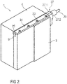
- FIG 2 shows a perspective representation of a part of the side wall plate 3, the support plate 5 and the cover plate 31 of the casting mold 1.
- the cover plate 31 is detachably connected to the upper side 24 of the side wall plate 3 by screw elements 33.
- the first area represents the side wall panel 3 in its new condition
- the second area represents the side wall panel 3 in the worn condition in which the side wall panel 3 needs to be replaced.
- the thickness of the side wall panel 3 is, for example, about 40 mm when new and about 25 mm when worn.
- the side wall panel 3 has, for example, a height in the range from about 700 mm to 1200 mm and a width in the range from about 60 mm to 3500 mm.
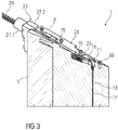
- FIG 3 shows the side wall plate 3, support plate 5 and measuring devices 7 of the casting mold 1 in a perspective sectional view.
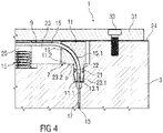
- FIG 4 shows a sectional view of the casting mold 1 in the area of the built-in part 11 of a measuring device 7.
- Each plate recess 23 in the side wall plate 3 is connected to a measuring channel 17 in the side wall plate 3 which is a vertically running bore in the side wall plate 3 .
- the measuring section 13 of a fiber optic sensor 9 runs in the measuring channel 17 and is guided out of the built-in part 11 which is arranged in the plate recess 23 connected to the measuring channel 17 .
- the measuring channel 17 has a diameter in the range of approximately 1 mm to 4 mm, for example.
- the measuring section 13 of a fiber optic sensor 9 has an optical waveguide with at least one fiber Bragg grating.
- the optical waveguide is arranged in a protective cannula.
- the protective cannula is made of stainless steel, for example, and has an outer diameter of about 1 mm to 3.8 mm, for example.
- the built-in part 11 of a measuring device 7 has a guide channel 19 in which a feed section 15.1 of the feed section 15 and a measuring end section 13.1 of the measuring section 13 of the fiber optic sensor 9 of the measuring device 7 are arranged and connected to one another.
- the feed section 15.1 and the measuring end section 13.1 of the fiber optic sensor 9 are glued to the built-in part 11, for example with an adhesive.
- the adhesive fills, for example, a gap between a guide channel wall of the guide channel 19 and the feed section 15.1 and the measuring end section 13.1 of the fiber optic sensor 9 completely.
- the built-in part 11 of a measuring device 7 has a nose-like sealing section 11.1, from which the measuring section 13 of the fiber-optic sensor 9 is led out.
- the built-in part 11 is inserted in the plate recess 23 used that a bearing surface 11.2 of the built-in part 11 contacts a support surface 23.2 of the plate recess 23 and the sealing section 11.1 is inserted into a corresponding sealing area 23.1 of the plate recess 23, which is connected to the measuring channel 17.
- the bearing surface 11.2 represents a reference point P, relative to which the at least one fiber Bragg grating of the fiber-optic sensor 9 is arranged at a predetermined distance.
- a sealing element 21 is arranged on the sealing section 11.1, which seals an intermediate space between the outer surface of the sealing section 11.1 and the wall of the sealing area 23.1.
- the sealing element 21 is an O-ring, which is arranged in an annular groove 22 in the sealing section 11.1.
- the built-in part 11 of a measuring device 7 is produced with a 3D print or as a turned part, a milled part or a welded part made of plastic or metal. Apart from the sealing section 11.1, the built-in part 11 is essentially cuboid with a height and width of, for example, approximately 30 mm each and a depth of, for example, approximately 18 mm.
- the feed channel 25 can be arranged entirely or partially in the support plate 5 .
- the sealing element 21 of a measuring device 7 can be designed as a different seal, for example as a flat seal, instead of as an O-ring.
- the measuring section 13 of a measuring device 7 through the entire Run the guide channel 19 of the built-in part 11 and be connected to the feed section 15 outside of the built-in part 11 .
- the supply section 15 of a measuring device 7 can have two supply sections, with a first supply section running completely outside of the built-in part 11 and having an elastic protective sheathing made of plastic, and a second supply section connecting the first supply section to the measuring section 13, running partially inside the built-in part 11 and one rigid, for example metallic protective coating.
- the ends of the feed sections 15 can be guided through the flange 27 and connected to the connecting optical waveguides 29 outside of the flange 27 .
- the cover plate 31 can be connected to the side wall plate 23 in a manner other than by screw elements 33, for example by gluing.
Landscapes
- Engineering & Computer Science (AREA)
- Mechanical Engineering (AREA)
- Manufacturing & Machinery (AREA)
- Physics & Mathematics (AREA)
- General Physics & Mathematics (AREA)
- Measuring Temperature Or Quantity Of Heat (AREA)
Priority Applications (2)
| Application Number | Priority Date | Filing Date | Title |
|---|---|---|---|
| EP20210150.7A EP4005697B1 (fr) | 2020-11-27 | 2020-11-27 | Dispositif et procede pour determiner la temperature dans une paroi laterale d'un moule de fonderie |
| CN202122930618.6U CN217466026U (zh) | 2020-11-27 | 2021-11-26 | 浇铸模和用于在浇铸模的侧壁板中的温度检测的测量设备 |
Applications Claiming Priority (1)
| Application Number | Priority Date | Filing Date | Title |
|---|---|---|---|
| EP20210150.7A EP4005697B1 (fr) | 2020-11-27 | 2020-11-27 | Dispositif et procede pour determiner la temperature dans une paroi laterale d'un moule de fonderie |
Publications (3)
| Publication Number | Publication Date |
|---|---|
| EP4005697A1 true EP4005697A1 (fr) | 2022-06-01 |
| EP4005697B1 EP4005697B1 (fr) | 2024-04-10 |
| EP4005697C0 EP4005697C0 (fr) | 2024-04-10 |
Family
ID=73642560
Family Applications (1)
| Application Number | Title | Priority Date | Filing Date |
|---|---|---|---|
| EP20210150.7A Active EP4005697B1 (fr) | 2020-11-27 | 2020-11-27 | Dispositif et procede pour determiner la temperature dans une paroi laterale d'un moule de fonderie |
Country Status (2)
| Country | Link |
|---|---|
| EP (1) | EP4005697B1 (fr) |
| CN (1) | CN217466026U (fr) |
Cited By (2)
| Publication number | Priority date | Publication date | Assignee | Title |
|---|---|---|---|---|
| DE102023205443A1 (de) | 2023-06-12 | 2024-12-12 | Sms Group Gmbh | Messvorrichtung zum Erfassen der Temperatur in einem Objekt |
| DE102023205442A1 (de) | 2023-06-12 | 2024-12-12 | Fisens Gmbh | Messvorrichtung zum Erfassen der Temperatur in einem Objekt |
Citations (5)
| Publication number | Priority date | Publication date | Assignee | Title |
|---|---|---|---|---|
| JP2008260046A (ja) * | 2007-04-12 | 2008-10-30 | Mishima Kosan Co Ltd | 連続鋳造用鋳型 |
| WO2011038876A1 (fr) * | 2009-09-30 | 2011-04-07 | Sms Siemag Ag | Elément capteur servant à mesurer un gradient de température |
| US20110186262A1 (en) * | 2008-06-25 | 2011-08-04 | Sms Siemag Aktiengesellschaft | Mold for casting metal |
| WO2017186702A1 (fr) | 2016-04-27 | 2017-11-02 | Primetals Technologies Austria GmbH | Implantation de guides optiques dans une paroi latérale d'une lingotière de coulée continue |
| EP3424614A1 (fr) | 2017-07-03 | 2019-01-09 | Primetals Technologies Austria GmbH | Montage d'un capteur de température à fibre optique dans un moule et moule comprenant plusieurs capteurs de température à fibre optique |
Family Cites Families (1)
| Publication number | Priority date | Publication date | Assignee | Title |
|---|---|---|---|---|
| US20110144790A1 (en) * | 2009-12-15 | 2011-06-16 | Terry Gerritsen | Thermal Sensing for Material Processing Assemblies |
-
2020
- 2020-11-27 EP EP20210150.7A patent/EP4005697B1/fr active Active
-
2021
- 2021-11-26 CN CN202122930618.6U patent/CN217466026U/zh active Active
Patent Citations (5)
| Publication number | Priority date | Publication date | Assignee | Title |
|---|---|---|---|---|
| JP2008260046A (ja) * | 2007-04-12 | 2008-10-30 | Mishima Kosan Co Ltd | 連続鋳造用鋳型 |
| US20110186262A1 (en) * | 2008-06-25 | 2011-08-04 | Sms Siemag Aktiengesellschaft | Mold for casting metal |
| WO2011038876A1 (fr) * | 2009-09-30 | 2011-04-07 | Sms Siemag Ag | Elément capteur servant à mesurer un gradient de température |
| WO2017186702A1 (fr) | 2016-04-27 | 2017-11-02 | Primetals Technologies Austria GmbH | Implantation de guides optiques dans une paroi latérale d'une lingotière de coulée continue |
| EP3424614A1 (fr) | 2017-07-03 | 2019-01-09 | Primetals Technologies Austria GmbH | Montage d'un capteur de température à fibre optique dans un moule et moule comprenant plusieurs capteurs de température à fibre optique |
Cited By (2)
| Publication number | Priority date | Publication date | Assignee | Title |
|---|---|---|---|---|
| DE102023205443A1 (de) | 2023-06-12 | 2024-12-12 | Sms Group Gmbh | Messvorrichtung zum Erfassen der Temperatur in einem Objekt |
| DE102023205442A1 (de) | 2023-06-12 | 2024-12-12 | Fisens Gmbh | Messvorrichtung zum Erfassen der Temperatur in einem Objekt |
Also Published As
| Publication number | Publication date |
|---|---|
| CN217466026U (zh) | 2022-09-20 |
| EP4005697B1 (fr) | 2024-04-10 |
| EP4005697C0 (fr) | 2024-04-10 |
Similar Documents
| Publication | Publication Date | Title |
|---|---|---|
| EP2293891B1 (fr) | Lingotière pour la coulée de métal | |
| EP3060364B1 (fr) | Lingotière de coulée continue équipée d'un capteur de température et procédé de fabrication de la lingotière de coulée continue équipée du capteur de température | |
| DE102006029529B4 (de) | Kabelführungsvorrichtung | |
| EP2483650B1 (fr) | Elément capteur servant à mesurer un gradient de température | |
| EP4005697B1 (fr) | Dispositif et procede pour determiner la temperature dans une paroi laterale d'un moule de fonderie | |
| DE102010016837A1 (de) | Faser-Bragg-Gitter-Messsystem | |
| DE102010013897B4 (de) | Optische Messeinrichtung und Lichtwellenleiter | |
| WO2019007656A1 (fr) | Installation d'un capteur de température à fibre optique dans une lingotière et lingotière pourvue de plusieurs capteurs de température à fibres optiques | |
| DE102012224161A1 (de) | Temperaturfühler für eine Kokille in einer Stranggießmaschine | |
| WO2011023377A2 (fr) | Surveillance de paliers de laminoir | |
| DE19941587B4 (de) | Linearlager mit einer Einrichtung zum Messen | |
| EP2573264B1 (fr) | Dispositif de racleur et agencement de racleurs destinés au fonctionnement avec un tel dispositif | |
| EP4088043B1 (fr) | Composants en plastique pour supports de câbles avec système de capteur intégré | |
| EP3448600A1 (fr) | Implantation de guides optiques dans une paroi latérale d'une lingotière de coulée continue | |
| EP0551581A1 (fr) | Quenouille pour récipients métallurgique | |
| EP3616807B1 (fr) | Petit côté de la coquille d'une lingotière de coulée continue à densités de points de mesure variables destiné à la détection améliorée de fissures longitudinales | |
| DE102009008909B4 (de) | Sensoreinheit mit einem Schutzprofil | |
| WO2001050552A1 (fr) | Boitier de protection de contact, pompe d'injection et procede pour monter un boitier de protection de contact au moyen d'un adaptateur | |
| DE102009060548B4 (de) | Kokille für eine Stranggießanlage und Verwendung einer solchen Kokille | |
| EP3546087B1 (fr) | Dispositif capteur de température, procédé de fabrication d'un dispositif capteur de température et composant doté d'un dispositif capteur de température | |
| EP3398699B1 (fr) | Méthode pour le réglage de la conicité d'un moule dans une machine de coulée continue et appareil pour ne machine de coulée continue | |
| DE3541445A1 (de) | Stranggiesskokille mit temperaturmesseinrichtungen | |
| EP0187993B1 (fr) | Dispositif pour le réglage d'une installation de coulée ou d'un convoyeur en remplissant un moule d'un métal liquide | |
| EP3546906B1 (fr) | Agencement de capteur de température, composant de capteur de température pour une installation métallurgique et procédé de fabrication d'un tel composant | |
| EP2857815A2 (fr) | Dispositif et procédé pour la surveillance d'une surface de réacteur |
Legal Events
| Date | Code | Title | Description |
|---|---|---|---|
| PUAI | Public reference made under article 153(3) epc to a published international application that has entered the european phase |
Free format text: ORIGINAL CODE: 0009012 |
|
| STAA | Information on the status of an ep patent application or granted ep patent |
Free format text: STATUS: THE APPLICATION HAS BEEN PUBLISHED |
|
| AK | Designated contracting states |
Kind code of ref document: A1 Designated state(s): AL AT BE BG CH CY CZ DE DK EE ES FI FR GB GR HR HU IE IS IT LI LT LU LV MC MK MT NL NO PL PT RO RS SE SI SK SM TR |
|
| STAA | Information on the status of an ep patent application or granted ep patent |
Free format text: STATUS: REQUEST FOR EXAMINATION WAS MADE |
|
| 17P | Request for examination filed |
Effective date: 20221201 |
|
| RBV | Designated contracting states (corrected) |
Designated state(s): AL AT BE BG CH CY CZ DE DK EE ES FI FR GB GR HR HU IE IS IT LI LT LU LV MC MK MT NL NO PL PT RO RS SE SI SK SM TR |
|
| STAA | Information on the status of an ep patent application or granted ep patent |
Free format text: STATUS: EXAMINATION IS IN PROGRESS |
|
| 17Q | First examination report despatched |
Effective date: 20230317 |
|
| GRAP | Despatch of communication of intention to grant a patent |
Free format text: ORIGINAL CODE: EPIDOSNIGR1 |
|
| STAA | Information on the status of an ep patent application or granted ep patent |
Free format text: STATUS: GRANT OF PATENT IS INTENDED |
|
| INTG | Intention to grant announced |
Effective date: 20231207 |
|
| GRAS | Grant fee paid |
Free format text: ORIGINAL CODE: EPIDOSNIGR3 |
|
| GRAA | (expected) grant |
Free format text: ORIGINAL CODE: 0009210 |
|
| STAA | Information on the status of an ep patent application or granted ep patent |
Free format text: STATUS: THE PATENT HAS BEEN GRANTED |
|
| AK | Designated contracting states |
Kind code of ref document: B1 Designated state(s): AL AT BE BG CH CY CZ DE DK EE ES FI FR GB GR HR HU IE IS IT LI LT LU LV MC MK MT NL NO PL PT RO RS SE SI SK SM TR |
|
| REG | Reference to a national code |
Ref country code: GB Ref legal event code: FG4D Free format text: NOT ENGLISH |
|
| REG | Reference to a national code |
Ref country code: CH Ref legal event code: EP |
|
| REG | Reference to a national code |
Ref country code: DE Ref legal event code: R096 Ref document number: 502020007610 Country of ref document: DE |
|
| REG | Reference to a national code |
Ref country code: IE Ref legal event code: FG4D Free format text: LANGUAGE OF EP DOCUMENT: GERMAN |
|
| U01 | Request for unitary effect filed |
Effective date: 20240410 |
|
| U07 | Unitary effect registered |
Designated state(s): AT BE BG DE DK EE FI FR IT LT LU LV MT NL PT SE SI Effective date: 20240416 |
|
| PG25 | Lapsed in a contracting state [announced via postgrant information from national office to epo] |
Ref country code: IS Free format text: LAPSE BECAUSE OF FAILURE TO SUBMIT A TRANSLATION OF THE DESCRIPTION OR TO PAY THE FEE WITHIN THE PRESCRIBED TIME-LIMIT Effective date: 20240810 |
|
| PG25 | Lapsed in a contracting state [announced via postgrant information from national office to epo] |
Ref country code: HR Free format text: LAPSE BECAUSE OF FAILURE TO SUBMIT A TRANSLATION OF THE DESCRIPTION OR TO PAY THE FEE WITHIN THE PRESCRIBED TIME-LIMIT Effective date: 20240410 |
|
| PG25 | Lapsed in a contracting state [announced via postgrant information from national office to epo] |
Ref country code: GR Free format text: LAPSE BECAUSE OF FAILURE TO SUBMIT A TRANSLATION OF THE DESCRIPTION OR TO PAY THE FEE WITHIN THE PRESCRIBED TIME-LIMIT Effective date: 20240711 |
|
| PG25 | Lapsed in a contracting state [announced via postgrant information from national office to epo] |
Ref country code: ES Free format text: LAPSE BECAUSE OF FAILURE TO SUBMIT A TRANSLATION OF THE DESCRIPTION OR TO PAY THE FEE WITHIN THE PRESCRIBED TIME-LIMIT Effective date: 20240410 |
|
| PG25 | Lapsed in a contracting state [announced via postgrant information from national office to epo] |
Ref country code: PL Free format text: LAPSE BECAUSE OF FAILURE TO SUBMIT A TRANSLATION OF THE DESCRIPTION OR TO PAY THE FEE WITHIN THE PRESCRIBED TIME-LIMIT Effective date: 20240410 |
|
| PG25 | Lapsed in a contracting state [announced via postgrant information from national office to epo] |
Ref country code: PL Free format text: LAPSE BECAUSE OF FAILURE TO SUBMIT A TRANSLATION OF THE DESCRIPTION OR TO PAY THE FEE WITHIN THE PRESCRIBED TIME-LIMIT Effective date: 20240410 Ref country code: NO Free format text: LAPSE BECAUSE OF FAILURE TO SUBMIT A TRANSLATION OF THE DESCRIPTION OR TO PAY THE FEE WITHIN THE PRESCRIBED TIME-LIMIT Effective date: 20240710 Ref country code: IS Free format text: LAPSE BECAUSE OF FAILURE TO SUBMIT A TRANSLATION OF THE DESCRIPTION OR TO PAY THE FEE WITHIN THE PRESCRIBED TIME-LIMIT Effective date: 20240810 Ref country code: HR Free format text: LAPSE BECAUSE OF FAILURE TO SUBMIT A TRANSLATION OF THE DESCRIPTION OR TO PAY THE FEE WITHIN THE PRESCRIBED TIME-LIMIT Effective date: 20240410 Ref country code: GR Free format text: LAPSE BECAUSE OF FAILURE TO SUBMIT A TRANSLATION OF THE DESCRIPTION OR TO PAY THE FEE WITHIN THE PRESCRIBED TIME-LIMIT Effective date: 20240711 Ref country code: ES Free format text: LAPSE BECAUSE OF FAILURE TO SUBMIT A TRANSLATION OF THE DESCRIPTION OR TO PAY THE FEE WITHIN THE PRESCRIBED TIME-LIMIT Effective date: 20240410 Ref country code: RS Free format text: LAPSE BECAUSE OF FAILURE TO SUBMIT A TRANSLATION OF THE DESCRIPTION OR TO PAY THE FEE WITHIN THE PRESCRIBED TIME-LIMIT Effective date: 20240710 |
|
| U20 | Renewal fee for the european patent with unitary effect paid |
Year of fee payment: 5 Effective date: 20241202 |
|
| REG | Reference to a national code |
Ref country code: DE Ref legal event code: R097 Ref document number: 502020007610 Country of ref document: DE |
|
| PG25 | Lapsed in a contracting state [announced via postgrant information from national office to epo] |
Ref country code: CZ Free format text: LAPSE BECAUSE OF FAILURE TO SUBMIT A TRANSLATION OF THE DESCRIPTION OR TO PAY THE FEE WITHIN THE PRESCRIBED TIME-LIMIT Effective date: 20240410 |
|
| PG25 | Lapsed in a contracting state [announced via postgrant information from national office to epo] |
Ref country code: RO Free format text: LAPSE BECAUSE OF FAILURE TO SUBMIT A TRANSLATION OF THE DESCRIPTION OR TO PAY THE FEE WITHIN THE PRESCRIBED TIME-LIMIT Effective date: 20240410 Ref country code: SK Free format text: LAPSE BECAUSE OF FAILURE TO SUBMIT A TRANSLATION OF THE DESCRIPTION OR TO PAY THE FEE WITHIN THE PRESCRIBED TIME-LIMIT Effective date: 20240410 |
|
| PG25 | Lapsed in a contracting state [announced via postgrant information from national office to epo] |
Ref country code: SM Free format text: LAPSE BECAUSE OF FAILURE TO SUBMIT A TRANSLATION OF THE DESCRIPTION OR TO PAY THE FEE WITHIN THE PRESCRIBED TIME-LIMIT Effective date: 20240410 |
|
| PG25 | Lapsed in a contracting state [announced via postgrant information from national office to epo] |
Ref country code: SM Free format text: LAPSE BECAUSE OF FAILURE TO SUBMIT A TRANSLATION OF THE DESCRIPTION OR TO PAY THE FEE WITHIN THE PRESCRIBED TIME-LIMIT Effective date: 20240410 Ref country code: SK Free format text: LAPSE BECAUSE OF FAILURE TO SUBMIT A TRANSLATION OF THE DESCRIPTION OR TO PAY THE FEE WITHIN THE PRESCRIBED TIME-LIMIT Effective date: 20240410 Ref country code: RO Free format text: LAPSE BECAUSE OF FAILURE TO SUBMIT A TRANSLATION OF THE DESCRIPTION OR TO PAY THE FEE WITHIN THE PRESCRIBED TIME-LIMIT Effective date: 20240410 Ref country code: CZ Free format text: LAPSE BECAUSE OF FAILURE TO SUBMIT A TRANSLATION OF THE DESCRIPTION OR TO PAY THE FEE WITHIN THE PRESCRIBED TIME-LIMIT Effective date: 20240410 |
|
| PLBE | No opposition filed within time limit |
Free format text: ORIGINAL CODE: 0009261 |
|
| STAA | Information on the status of an ep patent application or granted ep patent |
Free format text: STATUS: NO OPPOSITION FILED WITHIN TIME LIMIT |
|
| 26N | No opposition filed |
Effective date: 20250113 |
|
| REG | Reference to a national code |
Ref country code: CH Ref legal event code: PL |
|
| PG25 | Lapsed in a contracting state [announced via postgrant information from national office to epo] |
Ref country code: MC Free format text: LAPSE BECAUSE OF FAILURE TO SUBMIT A TRANSLATION OF THE DESCRIPTION OR TO PAY THE FEE WITHIN THE PRESCRIBED TIME-LIMIT Effective date: 20240410 |
|
| REG | Reference to a national code |
Ref country code: CH Ref legal event code: PL |
|
| GBPC | Gb: european patent ceased through non-payment of renewal fee |
Effective date: 20241127 |
|
| PG25 | Lapsed in a contracting state [announced via postgrant information from national office to epo] |
Ref country code: CH Free format text: LAPSE BECAUSE OF NON-PAYMENT OF DUE FEES Effective date: 20241130 |
|
| PG25 | Lapsed in a contracting state [announced via postgrant information from national office to epo] |
Ref country code: GB Free format text: LAPSE BECAUSE OF NON-PAYMENT OF DUE FEES Effective date: 20241127 |
|
| PG25 | Lapsed in a contracting state [announced via postgrant information from national office to epo] |
Ref country code: IE Free format text: LAPSE BECAUSE OF NON-PAYMENT OF DUE FEES Effective date: 20241127 |
|
| U20 | Renewal fee for the european patent with unitary effect paid |
Year of fee payment: 6 Effective date: 20251201 |
|
| PG25 | Lapsed in a contracting state [announced via postgrant information from national office to epo] |
Ref country code: HU Free format text: LAPSE BECAUSE OF FAILURE TO SUBMIT A TRANSLATION OF THE DESCRIPTION OR TO PAY THE FEE WITHIN THE PRESCRIBED TIME-LIMIT; INVALID AB INITIO Effective date: 20201127 |
|
| PG25 | Lapsed in a contracting state [announced via postgrant information from national office to epo] |
Ref country code: CY Free format text: LAPSE BECAUSE OF FAILURE TO SUBMIT A TRANSLATION OF THE DESCRIPTION OR TO PAY THE FEE WITHIN THE PRESCRIBED TIME-LIMIT; INVALID AB INITIO Effective date: 20201127 |
|
| PG25 | Lapsed in a contracting state [announced via postgrant information from national office to epo] |
Ref country code: TR Free format text: LAPSE BECAUSE OF FAILURE TO SUBMIT A TRANSLATION OF THE DESCRIPTION OR TO PAY THE FEE WITHIN THE PRESCRIBED TIME-LIMIT Effective date: 20240410 |