EP4005704B1 - Maschine zur herstellung von rohteilen aus keramik- oder metallmaterial - Google Patents
Maschine zur herstellung von rohteilen aus keramik- oder metallmaterial Download PDFInfo
- Publication number
- EP4005704B1 EP4005704B1 EP21209943.6A EP21209943A EP4005704B1 EP 4005704 B1 EP4005704 B1 EP 4005704B1 EP 21209943 A EP21209943 A EP 21209943A EP 4005704 B1 EP4005704 B1 EP 4005704B1
- Authority
- EP
- European Patent Office
- Prior art keywords
- suspension
- applicator
- layer
- machine according
- reserve
- Prior art date
- Legal status (The legal status is an assumption and is not a legal conclusion. Google has not performed a legal analysis and makes no representation as to the accuracy of the status listed.)
- Active
Links
Images



Classifications
-
- B—PERFORMING OPERATIONS; TRANSPORTING
- B22—CASTING; POWDER METALLURGY
- B22F—WORKING METALLIC POWDER; MANUFACTURE OF ARTICLES FROM METALLIC POWDER; MAKING METALLIC POWDER; APPARATUS OR DEVICES SPECIALLY ADAPTED FOR METALLIC POWDER
- B22F10/00—Additive manufacturing of workpieces or articles from metallic powder
- B22F10/10—Formation of a green body
-
- B—PERFORMING OPERATIONS; TRANSPORTING
- B22—CASTING; POWDER METALLURGY
- B22F—WORKING METALLIC POWDER; MANUFACTURE OF ARTICLES FROM METALLIC POWDER; MAKING METALLIC POWDER; APPARATUS OR DEVICES SPECIALLY ADAPTED FOR METALLIC POWDER
- B22F10/00—Additive manufacturing of workpieces or articles from metallic powder
- B22F10/10—Formation of a green body
- B22F10/12—Formation of a green body by photopolymerisation, e.g. stereolithography [SLA] or digital light processing [DLP]
-
- B—PERFORMING OPERATIONS; TRANSPORTING
- B22—CASTING; POWDER METALLURGY
- B22F—WORKING METALLIC POWDER; MANUFACTURE OF ARTICLES FROM METALLIC POWDER; MAKING METALLIC POWDER; APPARATUS OR DEVICES SPECIALLY ADAPTED FOR METALLIC POWDER
- B22F12/00—Apparatus or devices specially adapted for additive manufacturing; Auxiliary means for additive manufacturing; Combinations of additive manufacturing apparatus or devices with other processing apparatus or devices
- B22F12/22—Driving means
- B22F12/224—Driving means for motion along a direction within the plane of a layer
-
- B—PERFORMING OPERATIONS; TRANSPORTING
- B22—CASTING; POWDER METALLURGY
- B22F—WORKING METALLIC POWDER; MANUFACTURE OF ARTICLES FROM METALLIC POWDER; MAKING METALLIC POWDER; APPARATUS OR DEVICES SPECIALLY ADAPTED FOR METALLIC POWDER
- B22F12/00—Apparatus or devices specially adapted for additive manufacturing; Auxiliary means for additive manufacturing; Combinations of additive manufacturing apparatus or devices with other processing apparatus or devices
- B22F12/40—Radiation means
- B22F12/41—Radiation means characterised by the type, e.g. laser or electron beam
-
- B—PERFORMING OPERATIONS; TRANSPORTING
- B22—CASTING; POWDER METALLURGY
- B22F—WORKING METALLIC POWDER; MANUFACTURE OF ARTICLES FROM METALLIC POWDER; MAKING METALLIC POWDER; APPARATUS OR DEVICES SPECIALLY ADAPTED FOR METALLIC POWDER
- B22F12/00—Apparatus or devices specially adapted for additive manufacturing; Auxiliary means for additive manufacturing; Combinations of additive manufacturing apparatus or devices with other processing apparatus or devices
- B22F12/50—Means for feeding of material, e.g. heads
-
- B—PERFORMING OPERATIONS; TRANSPORTING
- B22—CASTING; POWDER METALLURGY
- B22F—WORKING METALLIC POWDER; MANUFACTURE OF ARTICLES FROM METALLIC POWDER; MAKING METALLIC POWDER; APPARATUS OR DEVICES SPECIALLY ADAPTED FOR METALLIC POWDER
- B22F12/00—Apparatus or devices specially adapted for additive manufacturing; Auxiliary means for additive manufacturing; Combinations of additive manufacturing apparatus or devices with other processing apparatus or devices
- B22F12/50—Means for feeding of material, e.g. heads
- B22F12/55—Two or more means for feeding material
-
- B—PERFORMING OPERATIONS; TRANSPORTING
- B22—CASTING; POWDER METALLURGY
- B22F—WORKING METALLIC POWDER; MANUFACTURE OF ARTICLES FROM METALLIC POWDER; MAKING METALLIC POWDER; APPARATUS OR DEVICES SPECIALLY ADAPTED FOR METALLIC POWDER
- B22F12/00—Apparatus or devices specially adapted for additive manufacturing; Auxiliary means for additive manufacturing; Combinations of additive manufacturing apparatus or devices with other processing apparatus or devices
- B22F12/50—Means for feeding of material, e.g. heads
- B22F12/57—Metering means
-
- B—PERFORMING OPERATIONS; TRANSPORTING
- B22—CASTING; POWDER METALLURGY
- B22F—WORKING METALLIC POWDER; MANUFACTURE OF ARTICLES FROM METALLIC POWDER; MAKING METALLIC POWDER; APPARATUS OR DEVICES SPECIALLY ADAPTED FOR METALLIC POWDER
- B22F12/00—Apparatus or devices specially adapted for additive manufacturing; Auxiliary means for additive manufacturing; Combinations of additive manufacturing apparatus or devices with other processing apparatus or devices
- B22F12/60—Planarisation devices; Compression devices
-
- B—PERFORMING OPERATIONS; TRANSPORTING
- B22—CASTING; POWDER METALLURGY
- B22F—WORKING METALLIC POWDER; MANUFACTURE OF ARTICLES FROM METALLIC POWDER; MAKING METALLIC POWDER; APPARATUS OR DEVICES SPECIALLY ADAPTED FOR METALLIC POWDER
- B22F12/00—Apparatus or devices specially adapted for additive manufacturing; Auxiliary means for additive manufacturing; Combinations of additive manufacturing apparatus or devices with other processing apparatus or devices
- B22F12/60—Planarisation devices; Compression devices
- B22F12/67—Blades
-
- B—PERFORMING OPERATIONS; TRANSPORTING
- B22—CASTING; POWDER METALLURGY
- B22F—WORKING METALLIC POWDER; MANUFACTURE OF ARTICLES FROM METALLIC POWDER; MAKING METALLIC POWDER; APPARATUS OR DEVICES SPECIALLY ADAPTED FOR METALLIC POWDER
- B22F12/00—Apparatus or devices specially adapted for additive manufacturing; Auxiliary means for additive manufacturing; Combinations of additive manufacturing apparatus or devices with other processing apparatus or devices
- B22F12/90—Means for process control, e.g. cameras or sensors
-
- B—PERFORMING OPERATIONS; TRANSPORTING
- B28—WORKING CEMENT, CLAY, OR STONE
- B28B—SHAPING CLAY OR OTHER CERAMIC COMPOSITIONS; SHAPING SLAG; SHAPING MIXTURES CONTAINING CEMENTITIOUS MATERIAL, e.g. PLASTER
- B28B1/00—Producing shaped prefabricated articles from the material
- B28B1/001—Rapid manufacturing of 3D objects by additive depositing, agglomerating or laminating of material
-
- B—PERFORMING OPERATIONS; TRANSPORTING
- B28—WORKING CEMENT, CLAY, OR STONE
- B28B—SHAPING CLAY OR OTHER CERAMIC COMPOSITIONS; SHAPING SLAG; SHAPING MIXTURES CONTAINING CEMENTITIOUS MATERIAL, e.g. PLASTER
- B28B11/00—Apparatus or processes for treating or working the shaped or preshaped articles
- B28B11/001—Applying decorations on shaped articles, e.g. by painting
-
- B—PERFORMING OPERATIONS; TRANSPORTING
- B28—WORKING CEMENT, CLAY, OR STONE
- B28B—SHAPING CLAY OR OTHER CERAMIC COMPOSITIONS; SHAPING SLAG; SHAPING MIXTURES CONTAINING CEMENTITIOUS MATERIAL, e.g. PLASTER
- B28B11/00—Apparatus or processes for treating or working the shaped or preshaped articles
- B28B11/04—Apparatus or processes for treating or working the shaped or preshaped articles for coating or applying engobing layers
-
- B—PERFORMING OPERATIONS; TRANSPORTING
- B29—WORKING OF PLASTICS; WORKING OF SUBSTANCES IN A PLASTIC STATE IN GENERAL
- B29C—SHAPING OR JOINING OF PLASTICS; SHAPING OF MATERIAL IN A PLASTIC STATE, NOT OTHERWISE PROVIDED FOR; AFTER-TREATMENT OF THE SHAPED PRODUCTS, e.g. REPAIRING
- B29C64/00—Additive manufacturing, i.e. manufacturing of three-dimensional [3D] objects by additive deposition, additive agglomeration or additive layering, e.g. by 3D printing, stereolithography or selective laser sintering
- B29C64/10—Processes of additive manufacturing
- B29C64/106—Processes of additive manufacturing using only liquids or viscous materials, e.g. depositing a continuous bead of viscous material
-
- B—PERFORMING OPERATIONS; TRANSPORTING
- B29—WORKING OF PLASTICS; WORKING OF SUBSTANCES IN A PLASTIC STATE IN GENERAL
- B29C—SHAPING OR JOINING OF PLASTICS; SHAPING OF MATERIAL IN A PLASTIC STATE, NOT OTHERWISE PROVIDED FOR; AFTER-TREATMENT OF THE SHAPED PRODUCTS, e.g. REPAIRING
- B29C64/00—Additive manufacturing, i.e. manufacturing of three-dimensional [3D] objects by additive deposition, additive agglomeration or additive layering, e.g. by 3D printing, stereolithography or selective laser sintering
- B29C64/10—Processes of additive manufacturing
- B29C64/106—Processes of additive manufacturing using only liquids or viscous materials, e.g. depositing a continuous bead of viscous material
- B29C64/124—Processes of additive manufacturing using only liquids or viscous materials, e.g. depositing a continuous bead of viscous material using layers of liquid which are selectively solidified
-
- B—PERFORMING OPERATIONS; TRANSPORTING
- B29—WORKING OF PLASTICS; WORKING OF SUBSTANCES IN A PLASTIC STATE IN GENERAL
- B29C—SHAPING OR JOINING OF PLASTICS; SHAPING OF MATERIAL IN A PLASTIC STATE, NOT OTHERWISE PROVIDED FOR; AFTER-TREATMENT OF THE SHAPED PRODUCTS, e.g. REPAIRING
- B29C64/00—Additive manufacturing, i.e. manufacturing of three-dimensional [3D] objects by additive deposition, additive agglomeration or additive layering, e.g. by 3D printing, stereolithography or selective laser sintering
- B29C64/20—Apparatus for additive manufacturing; Details thereof or accessories therefor
- B29C64/205—Means for applying layers
-
- B—PERFORMING OPERATIONS; TRANSPORTING
- B29—WORKING OF PLASTICS; WORKING OF SUBSTANCES IN A PLASTIC STATE IN GENERAL
- B29C—SHAPING OR JOINING OF PLASTICS; SHAPING OF MATERIAL IN A PLASTIC STATE, NOT OTHERWISE PROVIDED FOR; AFTER-TREATMENT OF THE SHAPED PRODUCTS, e.g. REPAIRING
- B29C64/00—Additive manufacturing, i.e. manufacturing of three-dimensional [3D] objects by additive deposition, additive agglomeration or additive layering, e.g. by 3D printing, stereolithography or selective laser sintering
- B29C64/20—Apparatus for additive manufacturing; Details thereof or accessories therefor
- B29C64/205—Means for applying layers
- B29C64/214—Doctor blades
-
- B—PERFORMING OPERATIONS; TRANSPORTING
- B33—ADDITIVE MANUFACTURING TECHNOLOGY
- B33Y—ADDITIVE MANUFACTURING, i.e. MANUFACTURING OF THREE-DIMENSIONAL [3D] OBJECTS BY ADDITIVE DEPOSITION, ADDITIVE AGGLOMERATION OR ADDITIVE LAYERING, e.g. BY 3D PRINTING, STEREOLITHOGRAPHY OR SELECTIVE LASER SINTERING
- B33Y10/00—Processes of additive manufacturing
-
- B—PERFORMING OPERATIONS; TRANSPORTING
- B33—ADDITIVE MANUFACTURING TECHNOLOGY
- B33Y—ADDITIVE MANUFACTURING, i.e. MANUFACTURING OF THREE-DIMENSIONAL [3D] OBJECTS BY ADDITIVE DEPOSITION, ADDITIVE AGGLOMERATION OR ADDITIVE LAYERING, e.g. BY 3D PRINTING, STEREOLITHOGRAPHY OR SELECTIVE LASER SINTERING
- B33Y30/00—Apparatus for additive manufacturing; Details thereof or accessories therefor
-
- B—PERFORMING OPERATIONS; TRANSPORTING
- B33—ADDITIVE MANUFACTURING TECHNOLOGY
- B33Y—ADDITIVE MANUFACTURING, i.e. MANUFACTURING OF THREE-DIMENSIONAL [3D] OBJECTS BY ADDITIVE DEPOSITION, ADDITIVE AGGLOMERATION OR ADDITIVE LAYERING, e.g. BY 3D PRINTING, STEREOLITHOGRAPHY OR SELECTIVE LASER SINTERING
- B33Y40/00—Auxiliary operations or equipment, e.g. for material handling
-
- B—PERFORMING OPERATIONS; TRANSPORTING
- B33—ADDITIVE MANUFACTURING TECHNOLOGY
- B33Y—ADDITIVE MANUFACTURING, i.e. MANUFACTURING OF THREE-DIMENSIONAL [3D] OBJECTS BY ADDITIVE DEPOSITION, ADDITIVE AGGLOMERATION OR ADDITIVE LAYERING, e.g. BY 3D PRINTING, STEREOLITHOGRAPHY OR SELECTIVE LASER SINTERING
- B33Y50/00—Data acquisition or data processing for additive manufacturing
- B33Y50/02—Data acquisition or data processing for additive manufacturing for controlling or regulating additive manufacturing processes
-
- B—PERFORMING OPERATIONS; TRANSPORTING
- B33—ADDITIVE MANUFACTURING TECHNOLOGY
- B33Y—ADDITIVE MANUFACTURING, i.e. MANUFACTURING OF THREE-DIMENSIONAL [3D] OBJECTS BY ADDITIVE DEPOSITION, ADDITIVE AGGLOMERATION OR ADDITIVE LAYERING, e.g. BY 3D PRINTING, STEREOLITHOGRAPHY OR SELECTIVE LASER SINTERING
- B33Y70/00—Materials specially adapted for additive manufacturing
-
- B—PERFORMING OPERATIONS; TRANSPORTING
- B22—CASTING; POWDER METALLURGY
- B22F—WORKING METALLIC POWDER; MANUFACTURE OF ARTICLES FROM METALLIC POWDER; MAKING METALLIC POWDER; APPARATUS OR DEVICES SPECIALLY ADAPTED FOR METALLIC POWDER
- B22F1/00—Metallic powder; Treatment of metallic powder, e.g. to facilitate working or to improve properties
- B22F1/10—Metallic powder containing lubricating or binding agents; Metallic powder containing organic material
-
- B—PERFORMING OPERATIONS; TRANSPORTING
- B22—CASTING; POWDER METALLURGY
- B22F—WORKING METALLIC POWDER; MANUFACTURE OF ARTICLES FROM METALLIC POWDER; MAKING METALLIC POWDER; APPARATUS OR DEVICES SPECIALLY ADAPTED FOR METALLIC POWDER
- B22F2999/00—Aspects linked to processes or compositions used in powder metallurgy
-
- B—PERFORMING OPERATIONS; TRANSPORTING
- B22—CASTING; POWDER METALLURGY
- B22F—WORKING METALLIC POWDER; MANUFACTURE OF ARTICLES FROM METALLIC POWDER; MAKING METALLIC POWDER; APPARATUS OR DEVICES SPECIALLY ADAPTED FOR METALLIC POWDER
- B22F3/00—Manufacture of workpieces or articles from metallic powder characterised by the manner of compacting or sintering; Apparatus specially adapted therefor ; Presses and furnaces
- B22F3/10—Sintering only
- B22F3/1017—Multiple heating or additional steps
- B22F3/1021—Removal of binder or filler
-
- B—PERFORMING OPERATIONS; TRANSPORTING
- B33—ADDITIVE MANUFACTURING TECHNOLOGY
- B33Y—ADDITIVE MANUFACTURING, i.e. MANUFACTURING OF THREE-DIMENSIONAL [3D] OBJECTS BY ADDITIVE DEPOSITION, ADDITIVE AGGLOMERATION OR ADDITIVE LAYERING, e.g. BY 3D PRINTING, STEREOLITHOGRAPHY OR SELECTIVE LASER SINTERING
- B33Y40/00—Auxiliary operations or equipment, e.g. for material handling
- B33Y40/20—Post-treatment, e.g. curing, coating or polishing
-
- Y—GENERAL TAGGING OF NEW TECHNOLOGICAL DEVELOPMENTS; GENERAL TAGGING OF CROSS-SECTIONAL TECHNOLOGIES SPANNING OVER SEVERAL SECTIONS OF THE IPC; TECHNICAL SUBJECTS COVERED BY FORMER USPC CROSS-REFERENCE ART COLLECTIONS [XRACs] AND DIGESTS
- Y02—TECHNOLOGIES OR APPLICATIONS FOR MITIGATION OR ADAPTATION AGAINST CLIMATE CHANGE
- Y02P—CLIMATE CHANGE MITIGATION TECHNOLOGIES IN THE PRODUCTION OR PROCESSING OF GOODS
- Y02P10/00—Technologies related to metal processing
- Y02P10/25—Process efficiency
Definitions
- the present invention relates to a machine for manufacturing raw parts made of ceramic or metallic material by stereolithography, such raw parts being intended to be subjected to cleaning, debinding and sintering operations to obtain finished ceramic or metallic parts.
- the green part is cleaned to remove uncured composition; the cleaned green part is debinded; and the cleaned and debinded green part is sintered to obtain the finished part.
- the curable composition may be in the form of a suspension.
- the rigid support is a work plate supporting the different layers of the part being built as well as the suspension and each of the layers is generally formed by lowering the work plate and spreading a predefined thickness of suspension.
- a reserve of suspension is stored in tanks (bins or cartridges or pressure pots) which are automatically emptied of a predefined quantity of suspension at each layer. This creates a bead or bead of suspension to be spread on the upper layer of the part being manufactured which will have been lowered previously by the work plate.
- Each layer is generally spread by a scraper which scans the work surface of the work table, for example by moving forward in a straight horizontal direction.
- the sausage comes out of its reservoir to extend over the width of the plate between the latter and the scraper to a height calculated so that the latter can be covered with suspension forming the layer as the scraper advances.
- US 5,922,364 a for the purpose of control systems for producing successive contiguous layers to form a three-dimensional object on a workpiece support surface.
- US 5,902,537 A The subject matter of the invention is a stereolithography system in which the spreading device has an external reservoir and a vacuum forming device.
- the applicant Company has proposed that the supply and spreading of suspension on the horizontal receiving surface for the first layer and on each previously hardened patterned layer for each other layer be carried out by an applicator system with a suspension reserve supplied by an external reservoir, the stacking of layers being carried out in a tank filling with suspension each time a layer is formed.
- the deposition of suspension can be carried out in a controlled manner advantageously over the entire width and length of the layers without excess suspension as in the situations previously described in the prior art.
- the progressive filling of the tank offers advantages over the case where one would work with a tank initially filled with the suspension into which one lowers step by step at each formation of layer a tray which supports the stacking to cover the layer with hardened pattern with a new layer to be irradiated.
- These advantages are those of avoiding a drop in reactivity of the suspension following an exchange with the ambient temperature, of avoiding sedimentation at the bottom of the tank of the ceramic or metallic part of the suspension, and to avoid high shear stress which would be necessary to lower a viscosity level of the suspension which is too high to allow it to properly coat the layers to be irradiated.
- said at least one vacuum forming device is connected to a vacuum tapping to control the quantity of suspension released by said at least one hole.
- the applicator may be a rectangular parallelepiped, the active face opposite the horizontal receiving surface being the release face of the applicator in which said at least one hole is formed.
- Said at least one formed hole, which is formed in the active face may consist of a single slot. formed over the entire width of the active face of the applicator or by a plurality of holes uniformly distributed over the entire width of the active face of the applicator.
- the suspension can be supplied to the reserve cavity by several feeds from the external reservoir, evenly distributed across the width of the applicator, internal suspension distribution tubes can be mounted dipping into the reserve cavity.
- the suspension reserve can advantageously be divided into compartments each associated with a vacuum forming device by at least one vacuum tapping and at least one suspension supply from the tank.
- each compartment has its own supply system and its own vacuum system.
- the advantage of supplying suspension while the applicator is moving is to minimize the amount of suspension in front of the applicator, which can cause mechanical stress phenomena on the parts or problems with beads during hardening, subsequently generating interference with the applicator.
- the machine according to the invention may comprise a sensor for the quantity of unhardened suspension in the tank, and an automaton regulating for each layer the supply of suspension by the applicator according to the level of unhardened suspension detected in the tank by the suspension quantity sensor.
- the suspension quantity sensor can be one of a level sensor and a volume sensor.
- the active face of the applicator may carry at least one blade configured to allow scraping of the suspension deposited by said at least one hole, said blade being located set back from said at least one hole in the direction of movement of the applicator.
- the front face of the applicator in the direction of travel may have a thrust shield shape.
- the tank can be equipped with an overflow to drain excess uncured suspension.
- the overflow can be controlled based on the suspension level detected by the uncured suspension quantity sensor in the tank.
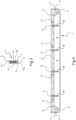
- a suspension applicator 1 has been shown having the general shape of a rectangular parallelepiped formed by an elongated upper plate 2, horizontal in the position of use, folded downwards at each of its ends to form transverse plates 3 of greater thickness.
- a side plate 4 is fixed by screws 5.
- the transverse plates 3 have holes 7 for the passage of fixing screws on an applicator holder 8.
- the latter equipped with its applicator 1, is slidably mounted on rails 9 which frame a horizontal receiving surface 10 (see Fig. 5 ).
- recesses 11 each capable of receiving an end connector 12 of a pipe 13.
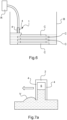
- the pipes 13 are connected to an intermediate connector 14 from which a pipe 15 departs, the two pipes 15 being joined to an intermediate connector (not shown) from which a pipe connecting to an external suspension tank (R on the Fig. 6 ).
- the recesses 11 are each connected to an internal suspension distribution tube 16 plunging into the reserve 6.
- the supply of suspension into the reserve 6 is controlled by a device (not shown) which is programmed to open one or more distribution valves to address suspension for example while the applicator 1 is stationary, in particular to a transverse edge of the receiving surface.
- vacuum tappings 17 are also made, connected two by two by pipes 18 to an intermediate connector 19 from which a connection to a vacuum forming device (not shown) starts.
- Each of the plates 4 has a scraping blade L along its lower edge in the example shown, this here having the shape of a thrust shield ( Fig. 3 ). Details regarding this form can be found in the French patent application filed on July 8, 2019 in the name of the present applicant and entitled "Device for applying layers of paste for an apparatus for manufacturing ceramic parts by stereolithography".
- Other forms of scraper blades can be used, such as beveled blades, for example with a high entry angle (for example 45°) or, if it is desired to promote laminar flow, with a smaller entry angle.
- FIG. 6 represents a machine according to the invention in which the applicator 1 rises each time by the height of one layer from the bottom of the tank B.
- an applicator 1' has been shown which differs from the applicator 1 in that the suspension reserve 6 is divided into compartments (four in the example shown) by three partitions 20 perpendicular to the upper plate 2 and extending downwards to the vicinity of the suspension outlet slot T.
- the compartments formed by the partitions 20 are substantially of the same volume and each is supplied with suspension by a pipe similar to a pipe 13 as shown in the Figure 5 , and is connected to a vacuum forming device by a vacuum tapping 17.
- the partitions 20 are beveled at their lower part, which makes it easier to exit the suspension from each of the compartments.
- Each compartment therefore has its own feed system and vacuum system, allowing the feed and vacuum to be controlled compartment by compartment.
- control windows 21 have also been shown which can, if desired, be made in the front wall 4 to observe the behavior of the suspension during its deposition.
Landscapes
- Engineering & Computer Science (AREA)
- Chemical & Material Sciences (AREA)
- Materials Engineering (AREA)
- Manufacturing & Machinery (AREA)
- Mechanical Engineering (AREA)
- Optics & Photonics (AREA)
- Physics & Mathematics (AREA)
- Ceramic Engineering (AREA)
- Structural Engineering (AREA)
- Analytical Chemistry (AREA)
- Automation & Control Theory (AREA)
- Plasma & Fusion (AREA)
- Health & Medical Sciences (AREA)
- General Health & Medical Sciences (AREA)
- Toxicology (AREA)
- Powder Metallurgy (AREA)
- Producing Shaped Articles From Materials (AREA)
- Devices For Post-Treatments, Processing, Supply, Discharge, And Other Processes (AREA)
Claims (12)
- - Maschine zur Herstellung von Teilen durch Stereolithographie-Technik, bei der Schichten einer Suspension, die unter der Wirkung einer Strahlung härtbar ist, nacheinander veranlasst werden, jeweils eine über der anderen durch Bestrahlung gemäß einem Muster, das für jede Schicht definiert ist, zu härten, die Maschine umfassend:- eine horizontale Aufnahmefläche (10), die konfiguriert ist, um die erste Schicht und die nachfolgenden Schichten, die eine über der anderen ausgehend von der ersten Schicht gebildet werden, aufzunehmen;- eine Zufuhr- und Ausbreitungsvorrichtung, die konfiguriert ist, um bei jeder Schichtbildung eine Menge an Suspension zuzuführen und sie auf der horizontalen Aufnahmefläche (10) für die erste Schicht und für jede nachfolgende Schicht auf jeder zuvor gehärteten gemusterten Schicht auszubreiten, wobei die Zufuhr- und Ausbreitungsvorrichtung und die horizontale Aufnahmefläche (10) in Bezug aufeinander in der Schichtstapelrichtung bewegbar sind; und- eine Bestrahlungsvorrichtung zum Bestrahlen jeder Schicht, sobald sie ausgebreitet ist, um sie in dem zuvor definierten Muster auszuhärten,dadurch gekennzeichnet, dass die horizontale Aufnahmefläche (10) durch den Boden eines Behälters (B) gebildet ist, wobei der Behälter (B) eine Länge und eine Breite aufweist, und dass die Zufuhr- und Ausbreitungsvorrichtung einen Suspensionsapplikator (1) und ein externes Reservoir (R) umfasst, der Suspensionsapplikator (1) umfassend einen Suspensionsvorrat (6), der von dem externen Reservoir (R) gespeist wird, mindestens eine Vakuumbildungsvorrichtung in dem Suspensionsvorrat (6) und mindestens ein Loch (T), das mit dem Suspensionsvorrat (6) verbunden ist und gegenüber der horizontalen Aufnahmefläche (10) gebildet ist, wobei die mindestens eine Vakuumbildungsvorrichtung gesteuert wird, um die Menge an Suspension zu regulieren, die durch das mindestens eine Loch (T) freigesetzt wird, wobei der Suspensionsapplikator (1) entlang der Breite des Behälters (B) angeordnet ist und mindestens die Druckbreite aufweist und konfiguriert ist, um sich translatorisch entlang der Länge des Behälters (B) zu bewegen, um geeignet zu sein, Suspension durch das mindestens eine Loch (T) auf die Aufnahmefläche (10) aufzutragen, und dass sie eine Steuerungsvorrichtung der Zufuhr an Suspension zu dem Hohlraum des Suspensionsvorrats (6) während der Translationsbewegung des Applikators (1) umfasst.
- - Maschine nach Anspruch 1, dadurch gekennzeichnet, dass die mindestens eine Vakuumbildungsvorrichtung mit einem Vakuumstecher (17) verbunden ist, um die Menge an Suspension zu steuern, die von dem mindestens einen Loch (T) freigesetzt wird.
- - Maschine nach einem der Ansprüche 1 oder 2, dadurch gekennzeichnet, dass der Applikator (1) ein rechteckiges Parallelepiped ist, wobei die aktive Fläche, die der horizontalen Aufnahmefläche (10) zugewandt ist, die Ausstoßfläche (FL) des Applikators (1) ist, in der das mindestens eine Loch (T) gebildet ist.
- - Maschine nach Anspruch 3, dadurch gekennzeichnet, dass das mindestens eine Loch (T), das in der aktiven Fläche gebildet ist, aus einem einzelnen Schlitz besteht, der über die gesamte Breite der aktiven Fläche des Applikators (1) gebildet ist, oder aus einer Vielzahl von Löchern, die gleichförmig über die gesamte Breite der aktiven Fläche des Applikators (1) verteilt sind.
- - Maschine nach einem der Ansprüche 3 oder 4, dadurch gekennzeichnet, dass die Suspension dem Vorratshohlraum (6) durch mehrere Zuführungen, die von dem externen Reservoir (R) herrühren, gleichförmig verteilt über die Breite des Applikators (1) zugeführt wird, wobei innere Suspensionsverteilungsrohre in den Vorratshohlraum eintauchend montierbar sind.
- - Maschine nach einem der Ansprüche 1 bis 5, dadurch gekennzeichnet, dass der Suspensionsvorrat (6) in Fächer unterteilt ist, die jeweils durch mindestens einen Vakuumstecher (17) und mit mindestens einer Suspensionszufuhr, die von dem Reservoir (R) herrührt, mit einer Vakuumbildungsvorrichtung verbunden sind.
- - Maschine nach einem der Ansprüche 1 bis 6, dadurch gekennzeichnet, dass sie ferner einen Sensor für die Menge an nicht ausgehärteter Suspension in dem Behälter (B) und einen Automaten, der für jede Schicht die Zufuhr von Suspension durch den Applikator abhängig von der Höhe der nicht ausgehärteten Suspension, die in dem Behälter (B) durch den Sensor für die Menge an Suspension erfasst wird, reguliert, umfasst.
- - Maschine nach Anspruch 7, dadurch gekennzeichnet, dass der Sensor für die Menge an Suspension einer von einem Füllstandsensor und einem Volumensensor ist.
- - Maschine nach einem der Ansprüche 4 bis 8, dadurch gekennzeichnet, dass die aktive Fläche des Applikators (1) mindestens eine Klinge (L) trägt, die konfiguriert ist, um ein Abstreifen der Suspension zu ermöglichen, die durch das mindestens eine Loch (T) aufgebracht wird, wobei sich die Klinge (L) in der Bewegungsrichtung des Applikators (1) von dem mindestens einen Loch (T) zurückversetzt befindet.
- - Maschine nach einem der Ansprüche 4 bis 8, dadurch gekennzeichnet, dass die Vorderseite (4) des Applikators (1) in der Bewegungsrichtung eine Form eines Schubschilds aufweist.
- - Maschine nach einem der Ansprüche 1 bis 10, dadurch gekennzeichnet, dass der Behälter (B) mit einem Überlauf ausgestattet ist, um überschüssige, nicht ausgehärtete Suspension abzuführen.
- - Maschine nach Anspruch 10, genommen in Kombination mit den Ansprüchen 7 bis 10, dadurch gekennzeichnet, dass der Überlauf abhängig von dem Stand der Suspension gesteuert wird, der durch den Sensor für die Menge an nicht ausgehärteter Suspension in dem Behälter (B) erfasst wird.
Applications Claiming Priority (1)
| Application Number | Priority Date | Filing Date | Title |
|---|---|---|---|
| FR2012228A FR3116461B1 (fr) | 2020-11-26 | 2020-11-26 | Machine de fabrication de pièces crues en matériau céramique ou métallique |
Publications (3)
| Publication Number | Publication Date |
|---|---|
| EP4005704A1 EP4005704A1 (de) | 2022-06-01 |
| EP4005704B1 true EP4005704B1 (de) | 2025-01-08 |
| EP4005704C0 EP4005704C0 (de) | 2025-01-08 |
Family
ID=74860054
Family Applications (1)
| Application Number | Title | Priority Date | Filing Date |
|---|---|---|---|
| EP21209943.6A Active EP4005704B1 (de) | 2020-11-26 | 2021-11-23 | Maschine zur herstellung von rohteilen aus keramik- oder metallmaterial |
Country Status (7)
| Country | Link |
|---|---|
| US (1) | US11794249B2 (de) |
| EP (1) | EP4005704B1 (de) |
| JP (1) | JP7312808B2 (de) |
| KR (1) | KR102628763B1 (de) |
| CN (1) | CN114535620B (de) |
| ES (1) | ES3010490T3 (de) |
| FR (1) | FR3116461B1 (de) |
Families Citing this family (3)
| Publication number | Priority date | Publication date | Assignee | Title |
|---|---|---|---|---|
| US20240198590A1 (en) * | 2022-12-14 | 2024-06-20 | Gulf Filtration Systems Inc. | Apparatus and methods for making three-dimensional objects using a heated recoater |
| CN116373297B (zh) * | 2023-03-10 | 2024-04-05 | 何海燕 | 一种带防串色功能的3d打印喷头供料结构及其使用方法 |
| FR3155735B1 (fr) | 2023-11-23 | 2026-01-30 | S A S 3Dceram Sinto | Procede de fabrication de pieces crues en materiau ceramique et/ou metallique par la technique des procedes additifs |
Citations (1)
| Publication number | Priority date | Publication date | Assignee | Title |
|---|---|---|---|---|
| US5902537A (en) * | 1995-02-01 | 1999-05-11 | 3D Systems, Inc. | Rapid recoating of three-dimensional objects formed on a cross-sectional basis |
Family Cites Families (39)
| Publication number | Priority date | Publication date | Assignee | Title |
|---|---|---|---|---|
| US3051567A (en) * | 1958-07-28 | 1962-08-28 | Fansteel Metallurgical Corp | Method and apparatus for making powdered metal articles |
| US5626919A (en) * | 1990-03-01 | 1997-05-06 | E. I. Du Pont De Nemours And Company | Solid imaging apparatus and method with coating station |
| US5248249A (en) * | 1990-07-27 | 1993-09-28 | Sony Corporation | Three-dimensional structure forming apparatus provided with a liquid-level control system for a main resin tank |
| JP3451108B2 (ja) * | 1993-04-21 | 2003-09-29 | 帝人製機株式会社 | 光硬化性樹脂の供給装置 |
| JP3396529B2 (ja) * | 1994-01-24 | 2003-04-14 | 帝人製機株式会社 | 光造形装置 |
| JPH08150662A (ja) * | 1994-11-30 | 1996-06-11 | Olympus Optical Co Ltd | 粉末混合光硬化性樹脂を用いた光造形装置及び光造形方法 |
| JPH09131799A (ja) * | 1995-11-09 | 1997-05-20 | Teijin Seiki Co Ltd | 光造形装置 |
| JP3245813B2 (ja) * | 1996-11-27 | 2002-01-15 | 東京エレクトロン株式会社 | 塗布膜形成装置 |
| US5922364A (en) * | 1997-03-03 | 1999-07-13 | Young, Jr.; Albert C. | Stereolithography layering control system |
| US5980812A (en) * | 1997-04-30 | 1999-11-09 | Lawton; John A. | Solid imaging process using component homogenization |
| JP4426060B2 (ja) * | 2000-05-12 | 2010-03-03 | ナブテスコ株式会社 | 光学的立体造形方法および装置 |
| EP1583950B1 (de) * | 2002-12-26 | 2017-04-05 | Meso Scale Technologies, LLC. | Testkassetten und verfahren zu ihrer verwendung |
| EP3831575B1 (de) * | 2003-05-01 | 2022-02-02 | Stratasys Ltd. | Vorrichtung zur herstellung eines gegenstands durch nacheinander auftragen von schichten aus konstruktionsmaterial |
| US6984583B2 (en) * | 2003-09-16 | 2006-01-10 | Micron Technology, Inc. | Stereolithographic method for forming insulative coatings for via holes in semiconductor devices |
| US20070075461A1 (en) * | 2005-09-30 | 2007-04-05 | 3D Systems, Inc. | Rapid prototyping and manufacturing system and method |
| TWI396593B (zh) * | 2006-03-31 | 2013-05-21 | Toray Industries | 塗布方法與塗布裝置以及顯示用構件之製造方法與製造裝置 |
| JP4925945B2 (ja) * | 2007-07-02 | 2012-05-09 | シーメット株式会社 | 光学的立体造形装置および光学的立体造形方法 |
| DE102008051478A1 (de) * | 2008-10-13 | 2010-06-02 | Eos Gmbh Electro Optical Systems | Rahmen für eine Vorrichtung zum Herstellen eines dreidimensionalen Objekts und Vorrichtung zum Herstellen eines dreidimensionalen Objekts mit einem solchen Rahmen |
| US8741203B2 (en) * | 2008-10-20 | 2014-06-03 | Ivoclar Vivadent Ag | Device and method for processing light-polymerizable material for building up an object in layers |
| DE102012219534A1 (de) * | 2012-10-25 | 2014-04-30 | Tools And Technologies Gmbh | Vorrichtung zum schichtweisen Herstellen eines Formkörpers |
| US10562226B1 (en) * | 2013-03-15 | 2020-02-18 | Southern Methodist University | Additive manufacturing of active devices using dielectric, conductive, and magnetic materials |
| CN106103025B (zh) * | 2014-03-13 | 2018-03-23 | 株式会社村田制作所 | 抽吸头及片材处理装置 |
| CN106457664B (zh) * | 2014-03-21 | 2019-12-13 | 莱恩奥罗克澳大利亚私人有限公司 | 一种合成复合物的方法和装置 |
| CA2859414C (en) * | 2014-04-04 | 2017-03-14 | Matsuura Machinery Corporation | Metal powder processing equipment |
| US11390062B2 (en) * | 2014-08-12 | 2022-07-19 | Carbon, Inc. | Three-dimensional printing with supported build plates |
| WO2016106136A2 (en) * | 2014-12-23 | 2016-06-30 | Stratasys, Inc. | Resin slot extruder for additive manufacturing system |
| JP6804850B2 (ja) * | 2016-02-26 | 2020-12-23 | 東レ株式会社 | 塗布装置及び塗布方法 |
| GB2550336A (en) * | 2016-05-12 | 2017-11-22 | Hewlett Packard Development Co Lp | Build material management station |
| CN105880598B (zh) * | 2016-06-03 | 2018-02-09 | 梁福鹏 | 一种金属三维打印方法及其设备 |
| CN106622413A (zh) * | 2016-12-28 | 2017-05-10 | 华东理工大学 | 基于3d打印的多喷嘴模块及其大批量生产颗粒的装置和技术 |
| FR3063450B1 (fr) * | 2017-03-01 | 2019-03-22 | S.A.S 3Dceram-Sinto | Procede et machine de fabrication de pieces par la technique des procedes additifs par voie pateuse avec amenee de pate perfectionnee |
| WO2018213356A1 (en) * | 2017-05-15 | 2018-11-22 | Holo, Inc. | Viscous film three-dimensional printing systems and methods |
| US10688593B2 (en) * | 2017-06-19 | 2020-06-23 | General Electric Company | Additive manufactured component with enlarged width area in channel at melting beams' field interface |
| CN207432784U (zh) * | 2017-08-18 | 2018-06-01 | 佛山吗卡工程技术有限公司 | 一种用于sla 3d打印机的真空刮刀装置 |
| US11273495B2 (en) * | 2017-10-02 | 2022-03-15 | General Electric Company | Modified frame and recoating system |
| US12285910B2 (en) * | 2017-12-15 | 2025-04-29 | Virginia Tech Intellectual Properties, Inc. | High-temperature stereolithography apparatus and methods of use thereof |
| CN208343464U (zh) * | 2018-05-30 | 2019-01-08 | 合肥伽利洛精密机械有限公司 | 一种sla刮平装置 |
| CN110920055A (zh) * | 2018-09-04 | 2020-03-27 | 三纬国际立体列印科技股份有限公司 | 提升材料注入效率的3d打印方法 |
| FR3098438B1 (fr) | 2019-07-08 | 2021-06-11 | S A S 3Dceram Sinto | Dispositif d’application de couches de pâte pour un appareil de fabrication de pieces ceramiques par stereolithographie |
-
2020
- 2020-11-26 FR FR2012228A patent/FR3116461B1/fr active Active
-
2021
- 2021-11-17 JP JP2021186729A patent/JP7312808B2/ja active Active
- 2021-11-23 ES ES21209943T patent/ES3010490T3/es active Active
- 2021-11-23 EP EP21209943.6A patent/EP4005704B1/de active Active
- 2021-11-25 KR KR1020210164300A patent/KR102628763B1/ko active Active
- 2021-11-26 CN CN202111421585.0A patent/CN114535620B/zh active Active
- 2021-11-26 US US17/535,826 patent/US11794249B2/en active Active
Patent Citations (1)
| Publication number | Priority date | Publication date | Assignee | Title |
|---|---|---|---|---|
| US5902537A (en) * | 1995-02-01 | 1999-05-11 | 3D Systems, Inc. | Rapid recoating of three-dimensional objects formed on a cross-sectional basis |
Also Published As
| Publication number | Publication date |
|---|---|
| FR3116461B1 (fr) | 2022-12-23 |
| JP7312808B2 (ja) | 2023-07-21 |
| FR3116461A1 (fr) | 2022-05-27 |
| US20220161323A1 (en) | 2022-05-26 |
| KR20220073678A (ko) | 2022-06-03 |
| KR102628763B1 (ko) | 2024-01-24 |
| ES3010490T3 (en) | 2025-04-03 |
| EP4005704A1 (de) | 2022-06-01 |
| CN114535620A (zh) | 2022-05-27 |
| US11794249B2 (en) | 2023-10-24 |
| JP2022084545A (ja) | 2022-06-07 |
| CN114535620B (zh) | 2024-07-16 |
| EP4005704C0 (de) | 2025-01-08 |
Similar Documents
| Publication | Publication Date | Title |
|---|---|---|
| EP3369555B1 (de) | Verfahren und maschine zur herstellung von bauteilen mithilfe der technik der additiven fertigung mit pastösen stoffen und perfektionierter stoffzufuhr | |
| EP4005704A1 (de) | Maschine zur herstellung von rohteilen aus keramik- oder metallmaterial | |
| EP3444050B1 (de) | Verfahren und maschine zur herstellung von mindestens einem werkstück aus mindestens einem keramik- und/oder metallwerkstoff mithilfe der technik der additiven fertigung | |
| EP3670149B1 (de) | Verfahren zur generativen fertigung mit mehreren materialien | |
| EP3478222B1 (de) | Verfahren zur herstellung eines herausnehmbaren partiellen zahnersatzes durch formung mithilfe einer durch generative fertigung hergestellten form | |
| JP4348040B2 (ja) | 迅速プロトタイプ製造方法および装置 | |
| US20190126536A1 (en) | Cartridge vat-based additive manufacturing apparatus and method | |
| EP3427924A1 (de) | Verfahren und maschine zur herstellung von rohlingen aus keramik- und/oder metallwerkstoff mithilfe der technik der additiven fertigung | |
| CN108430674B (zh) | 包括具有托盘和注射器的粉末分布系统的增材制造机器 | |
| JPH10513130A (ja) | 3次元物体の高速断面積層方法 | |
| CN107148336A (zh) | 用于制造三维物体的方法、装置和重涂模块 | |
| EP4116066B1 (de) | Verfahren zur generativen fertigung für funktionell gradiertes material | |
| EP3393697B1 (de) | Verfahren zur generativen fertigung mit einem pulververteilungsschritt durch einen injektor | |
| EP3444049B1 (de) | Verfahren und maschine zur herstellung von rohlingen aus keramik- und/oder metallwerkstoff mithilfe der technik der additiven fertigung | |
| CN108215172B (zh) | 一种三维打印机 | |
| EP3763511A1 (de) | Vorrichtung zum aufbringen von pastenartigen schichten für eine maschine zur herstellung von keramikgegenständen mithilfe von stereolithographie | |
| FR3002179A1 (fr) | Systeme de prototypage rapide d'un objet par extrusion de matiere | |
| FR2668086A1 (fr) | Procede et installation pour moulage en fonderie du type a modele perdu. | |
| CA3028891C (fr) | Procede de fabrication d'une prothese dentaire amovible par moulage a l'aide d'un moule realise en fabrication additive | |
| FR3015345A1 (fr) | Dispositif de prototypage d'objets et procede associe | |
| FR3082141A1 (fr) | Dispositif de fabrication | |
| FR2489723A1 (fr) | Procede et dispositif pour la realisation d'un moule pour l'execution d'une piece par coulee d'une matiere premiere en fusion |
Legal Events
| Date | Code | Title | Description |
|---|---|---|---|
| PUAI | Public reference made under article 153(3) epc to a published international application that has entered the european phase |
Free format text: ORIGINAL CODE: 0009012 |
|
| STAA | Information on the status of an ep patent application or granted ep patent |
Free format text: STATUS: THE APPLICATION HAS BEEN PUBLISHED |
|
| STAA | Information on the status of an ep patent application or granted ep patent |
Free format text: STATUS: REQUEST FOR EXAMINATION WAS MADE |
|
| AK | Designated contracting states |
Kind code of ref document: A1 Designated state(s): AL AT BE BG CH CY CZ DE DK EE ES FI FR GB GR HR HU IE IS IT LI LT LU LV MC MK MT NL NO PL PT RO RS SE SI SK SM TR |
|
| 17P | Request for examination filed |
Effective date: 20220516 |
|
| RBV | Designated contracting states (corrected) |
Designated state(s): AL AT BE BG CH CY CZ DE DK EE ES FI FR GB GR HR HU IE IS IT LI LT LU LV MC MK MT NL NO PL PT RO RS SE SI SK SM TR |
|
| STAA | Information on the status of an ep patent application or granted ep patent |
Free format text: STATUS: EXAMINATION IS IN PROGRESS |
|
| 17Q | First examination report despatched |
Effective date: 20231214 |
|
| GRAP | Despatch of communication of intention to grant a patent |
Free format text: ORIGINAL CODE: EPIDOSNIGR1 |
|
| STAA | Information on the status of an ep patent application or granted ep patent |
Free format text: STATUS: GRANT OF PATENT IS INTENDED |
|
| INTG | Intention to grant announced |
Effective date: 20240627 |
|
| GRAS | Grant fee paid |
Free format text: ORIGINAL CODE: EPIDOSNIGR3 |
|
| GRAA | (expected) grant |
Free format text: ORIGINAL CODE: 0009210 |
|
| STAA | Information on the status of an ep patent application or granted ep patent |
Free format text: STATUS: THE PATENT HAS BEEN GRANTED |
|
| AK | Designated contracting states |
Kind code of ref document: B1 Designated state(s): AL AT BE BG CH CY CZ DE DK EE ES FI FR GB GR HR HU IE IS IT LI LT LU LV MC MK MT NL NO PL PT RO RS SE SI SK SM TR |
|
| REG | Reference to a national code |
Ref country code: GB Ref legal event code: FG4D Free format text: NOT ENGLISH |
|
| REG | Reference to a national code |
Ref country code: CH Ref legal event code: EP |
|
| REG | Reference to a national code |
Ref country code: DE Ref legal event code: R096 Ref document number: 602021024613 Country of ref document: DE |
|
| REG | Reference to a national code |
Ref country code: IE Ref legal event code: FG4D Free format text: LANGUAGE OF EP DOCUMENT: FRENCH |
|
| U01 | Request for unitary effect filed |
Effective date: 20250205 |
|
| U07 | Unitary effect registered |
Designated state(s): AT BE BG DE DK EE FI FR IT LT LU LV MT NL PT RO SE SI Effective date: 20250211 |
|
| PG25 | Lapsed in a contracting state [announced via postgrant information from national office to epo] |
Ref country code: RS Free format text: LAPSE BECAUSE OF FAILURE TO SUBMIT A TRANSLATION OF THE DESCRIPTION OR TO PAY THE FEE WITHIN THE PRESCRIBED TIME-LIMIT Effective date: 20250408 |
|
| PG25 | Lapsed in a contracting state [announced via postgrant information from national office to epo] |
Ref country code: PL Free format text: LAPSE BECAUSE OF FAILURE TO SUBMIT A TRANSLATION OF THE DESCRIPTION OR TO PAY THE FEE WITHIN THE PRESCRIBED TIME-LIMIT Effective date: 20250108 |
|
| PG25 | Lapsed in a contracting state [announced via postgrant information from national office to epo] |
Ref country code: IS Free format text: LAPSE BECAUSE OF FAILURE TO SUBMIT A TRANSLATION OF THE DESCRIPTION OR TO PAY THE FEE WITHIN THE PRESCRIBED TIME-LIMIT Effective date: 20250508 Ref country code: NO Free format text: LAPSE BECAUSE OF FAILURE TO SUBMIT A TRANSLATION OF THE DESCRIPTION OR TO PAY THE FEE WITHIN THE PRESCRIBED TIME-LIMIT Effective date: 20250408 |
|
| PG25 | Lapsed in a contracting state [announced via postgrant information from national office to epo] |
Ref country code: HR Free format text: LAPSE BECAUSE OF FAILURE TO SUBMIT A TRANSLATION OF THE DESCRIPTION OR TO PAY THE FEE WITHIN THE PRESCRIBED TIME-LIMIT Effective date: 20250108 |
|
| PG25 | Lapsed in a contracting state [announced via postgrant information from national office to epo] |
Ref country code: GR Free format text: LAPSE BECAUSE OF FAILURE TO SUBMIT A TRANSLATION OF THE DESCRIPTION OR TO PAY THE FEE WITHIN THE PRESCRIBED TIME-LIMIT Effective date: 20250409 |
|
| PG25 | Lapsed in a contracting state [announced via postgrant information from national office to epo] |
Ref country code: SM Free format text: LAPSE BECAUSE OF FAILURE TO SUBMIT A TRANSLATION OF THE DESCRIPTION OR TO PAY THE FEE WITHIN THE PRESCRIBED TIME-LIMIT Effective date: 20250108 |
|
| PG25 | Lapsed in a contracting state [announced via postgrant information from national office to epo] |
Ref country code: CZ Free format text: LAPSE BECAUSE OF FAILURE TO SUBMIT A TRANSLATION OF THE DESCRIPTION OR TO PAY THE FEE WITHIN THE PRESCRIBED TIME-LIMIT Effective date: 20250108 |
|
| PG25 | Lapsed in a contracting state [announced via postgrant information from national office to epo] |
Ref country code: SK Free format text: LAPSE BECAUSE OF FAILURE TO SUBMIT A TRANSLATION OF THE DESCRIPTION OR TO PAY THE FEE WITHIN THE PRESCRIBED TIME-LIMIT Effective date: 20250108 |
|
| PLBE | No opposition filed within time limit |
Free format text: ORIGINAL CODE: 0009261 |
|
| STAA | Information on the status of an ep patent application or granted ep patent |
Free format text: STATUS: NO OPPOSITION FILED WITHIN TIME LIMIT |
|
| REG | Reference to a national code |
Ref country code: CH Ref legal event code: L10 Free format text: ST27 STATUS EVENT CODE: U-0-0-L10-L00 (AS PROVIDED BY THE NATIONAL OFFICE) Effective date: 20251119 |
|
| REG | Reference to a national code |
Ref country code: CH Ref legal event code: U11 Free format text: ST27 STATUS EVENT CODE: U-0-0-U10-U11 (AS PROVIDED BY THE NATIONAL OFFICE) Effective date: 20251201 |
|
| 26N | No opposition filed |
Effective date: 20251009 |
|
| U20 | Renewal fee for the european patent with unitary effect paid |
Year of fee payment: 5 Effective date: 20251127 |
|
| PGFP | Annual fee paid to national office [announced via postgrant information from national office to epo] |
Ref country code: GB Payment date: 20251119 Year of fee payment: 5 |
|
| PGFP | Annual fee paid to national office [announced via postgrant information from national office to epo] |
Ref country code: CH Payment date: 20251201 Year of fee payment: 5 |
|
| PGFP | Annual fee paid to national office [announced via postgrant information from national office to epo] |
Ref country code: ES Payment date: 20251204 Year of fee payment: 5 |
|
| PG25 | Lapsed in a contracting state [announced via postgrant information from national office to epo] |
Ref country code: MC Free format text: LAPSE BECAUSE OF FAILURE TO SUBMIT A TRANSLATION OF THE DESCRIPTION OR TO PAY THE FEE WITHIN THE PRESCRIBED TIME-LIMIT Effective date: 20250108 |