EP4005735A1 - Werkzeugmaschine mit gewindespindeltrieb - Google Patents
Werkzeugmaschine mit gewindespindeltrieb Download PDFInfo
- Publication number
- EP4005735A1 EP4005735A1 EP21156580.9A EP21156580A EP4005735A1 EP 4005735 A1 EP4005735 A1 EP 4005735A1 EP 21156580 A EP21156580 A EP 21156580A EP 4005735 A1 EP4005735 A1 EP 4005735A1
- Authority
- EP
- European Patent Office
- Prior art keywords
- threaded spindle
- machine tool
- drive
- spindle part
- tool according
- Prior art date
- Legal status (The legal status is an assumption and is not a legal conclusion. Google has not performed a legal analysis and makes no representation as to the accuracy of the status listed.)
- Granted
Links
Images


Classifications
-
- B—PERFORMING OPERATIONS; TRANSPORTING
- B25—HAND TOOLS; PORTABLE POWER-DRIVEN TOOLS; MANIPULATORS
- B25B—TOOLS OR BENCH DEVICES NOT OTHERWISE PROVIDED FOR, FOR FASTENING, CONNECTING, DISENGAGING, OR HOLDING
- B25B27/00—Hand tools, specially adapted for fitting together or separating parts or objects whether or not involving some deformation, not otherwise provided for
- B25B27/02—Hand tools, specially adapted for fitting together or separating parts or objects whether or not involving some deformation, not otherwise provided for for connecting objects by press fit or detaching same
- B25B27/10—Hand tools, specially adapted for fitting together or separating parts or objects whether or not involving some deformation, not otherwise provided for for connecting objects by press fit or detaching same inserting fittings into hoses
-
- B—PERFORMING OPERATIONS; TRANSPORTING
- B21—MECHANICAL METAL-WORKING WITHOUT ESSENTIALLY REMOVING MATERIAL; PUNCHING METAL
- B21D—WORKING OR PROCESSING OF SHEET METAL OR METAL TUBES, RODS OR PROFILES WITHOUT ESSENTIALLY REMOVING MATERIAL; PUNCHING METAL
- B21D39/00—Application of procedures in order to connect objects or parts, e.g. coating with sheet metal otherwise than by plating; Tube expanders
- B21D39/04—Application of procedures in order to connect objects or parts, e.g. coating with sheet metal otherwise than by plating; Tube expanders of tubes with tubes; of tubes with rods
- B21D39/046—Connecting tubes to tube-like fittings
-
- B—PERFORMING OPERATIONS; TRANSPORTING
- B21—MECHANICAL METAL-WORKING WITHOUT ESSENTIALLY REMOVING MATERIAL; PUNCHING METAL
- B21D—WORKING OR PROCESSING OF SHEET METAL OR METAL TUBES, RODS OR PROFILES WITHOUT ESSENTIALLY REMOVING MATERIAL; PUNCHING METAL
- B21D39/00—Application of procedures in order to connect objects or parts, e.g. coating with sheet metal otherwise than by plating; Tube expanders
- B21D39/04—Application of procedures in order to connect objects or parts, e.g. coating with sheet metal otherwise than by plating; Tube expanders of tubes with tubes; of tubes with rods
- B21D39/048—Application of procedures in order to connect objects or parts, e.g. coating with sheet metal otherwise than by plating; Tube expanders of tubes with tubes; of tubes with rods using presses for radially crimping tubular elements
-
- B—PERFORMING OPERATIONS; TRANSPORTING
- B25—HAND TOOLS; PORTABLE POWER-DRIVEN TOOLS; MANIPULATORS
- B25B—TOOLS OR BENCH DEVICES NOT OTHERWISE PROVIDED FOR, FOR FASTENING, CONNECTING, DISENGAGING, OR HOLDING
- B25B25/00—Implements for fastening, connecting or tensioning of wire or strip
- B25B25/005—Implements for fastening, connecting or tensioning of wire or strip for applying wire clasps to hose couplings
Definitions
- the invention relates to a machine tool, in particular a pipe press, containing a drive, an output shaft, a threaded spindle drive and a linear actuator, wherein a torque generated by the drive can be transmitted to the linear actuator via the output shaft and the threaded spindle drive connected to the output shaft.
- the forming machines available on the market have a press head driven by a press cylinder.
- the press cylinder for moving the press head is often driven hydraulically.
- An electric motor in turn drives a hydraulic pump, which drives the linear movement of the press cylinder.
- mechanical pressing/cutting and crimping machine tools are also known which, instead of hydraulics, generate the pressing pressure via a threaded spindle drive in combination with an electric motor.
- the rotary movement of the electric motor is transformed into a linear movement via a threaded spindle.
- These machine tools often contain a gearbox connected between the spindle and the electric motor in order to reduce the required motor torque and thereby allow the motor to be dimensioned smaller.
- machine tools known from the prior art with hydraulically driven linear actuators tend to be too complex to develop and to be too large or too long, inefficient and too heavy to handle.
- machine tools known from the prior art with hydraulically driven linear actuators require a relatively long time for a single work cycle, with a work cycle being able to be a forming or cutting cycle, for example.
- the object of the present invention is therefore to offer a machine tool of the type described at the outset that is particularly inexpensive and offers high efficiency with a very high load-carrying capacity.
- a machine tool in particular a pipe press, containing a drive, an output shaft, a threaded spindle drive and a linear actuator, wherein a torque generated by the drive can be transmitted to the linear actuator via the output shaft and the threaded spindle drive connected to the output shaft
- the Threaded spindle drive has an inner threaded spindle part with an external thread and an outer threaded spindle part with an internal thread, wherein the internal thread interacts with the external thread via at least one bearing roller and the at least one bearing roller has at least one radially circumferential groove, with which the bearing roller is inserted into the external thread and into the internal thread engages.
- the at least one bearing roller has one or more radially circumferential grooves.
- the at least one groove means that no screw thread is formed on the bearing roller.
- the bearing roller is therefore kept structurally very simple and can therefore be produced inexpensively.
- the bearing roller can roll on the internal and external threads.
- the bearing roller thus forms a roller bearing which can have particularly low rolling friction compared to, for example, sliding friction.
- the threaded spindle drive can thus have only low friction losses and thus a particularly favorable efficiency for converting the rotational movement into a translation, in particular parallel to an axial direction of the threaded spindle drive.
- the more radially circumferential grooves the bearing roller has, the higher loads can be transmitted and/or generated along the axial direction of the threaded spindle drive.
- the machine tool can preferably be a mobile machine tool, for example a hand-held machine tool or a mobile construction robot, in particular for work in building construction and/or in civil engineering, for example for installation work.
- the machine tool can a pressing device, a separating device, for example a separating shears, and/or a crimping device.
- Preferred embodiments of the invention can have several bearing rollers, in particular 3, 4, 6, 8, 10, 12 or 13 bearing rollers.
- the bearing rollers can be distributed evenly over the circumference of the inner threaded spindle part.
- the internal thread and/or the external thread are preferably single-start.
- a simple assembly, in particular a partial pre-assembly, is possible if the at least one bearing roller is accommodated in a cage. If several bearing rollers are provided, a cage can particularly facilitate an arrangement of the bearing rollers distributed uniformly along the circumference of the inner threaded spindle part.
- the cage and/or the rollers can have a degree of translational freedom, in particular parallel to the axial direction, relative to the rest of the threaded spindle drive.
- a translation of the cage and/or the rollers can thus be possible, in particular parallel to the longitudinal axis of the threaded spindle drive.
- it can be set up that when the inner threaded spindle part rotates relative to the outer threaded spindle part, the cage together with the rollers, or if there is no cage, the rollers alone, is displaced along the axial direction relative to the inner threaded spindle part and/or relative to the outer threaded spindle part or relocate.
- the outer threaded spindle part can be non-rotatably and/or non-displaceably fixed relative to a housing of the machine tool.
- the relative rotation can thus lead to a translation of the inner threaded spindle part relative to the housing.
- the linear actuator can be and/or can be actuated by the inner threaded spindle part, in particular by the relative rotation.
- the outer threaded spindle part can also be longer than the at least one bearing roller. Alternatively or additionally, the outer threaded spindle part can be longer than the cage. Thus, the bearing rollers and/or the cage, if present, can be displaced at least a certain distance in the axial direction without the area of the outer to leave the threaded spindle part.
- the outer threaded spindle part can particularly preferably be at least twice as long as the at least one bearing roller and/or, if present, the cage.
- the linear actuator is rotatably mounted on the inner threaded spindle part along the longitudinal axis of the inner threaded spindle part, so that the linear actuator can be and/or is decoupled from rotations of the inner threaded spindle part, in particular relative to the housing.
- a ball bearing and/or a roller bearing can be arranged between the inner threaded spindle part and the linear actuator.
- the threaded spindle drive preferably the inner threaded spindle part
- the threaded spindle drive can be driven by the drive via a telescoping shaft device, so that the torque from the drive can be transmitted to the threaded spindle drive, in particular to the inner threaded spindle part, even when the inner threaded spindle part is translated in the axial direction .
- the output shaft can be designed as a telescoping shaft device.
- the telescoping shaft device can be designed as part of the output shaft.
- the telescoping shaft device can have a groove element provided with one or more longitudinal grooves, on which a fitting piece can preferably be guided.
- the machine tool can have a particularly long service life, which in turn can improve the cost efficiency of the machine tool over the service life.
- the torque can be and/or can be transmitted to the threaded spindle drive via a gear device, in particular via a reduction gear, particularly preferably via an eccentric gear device.
- a gear device in particular via a reduction gear, particularly preferably via an eccentric gear device.
- a reduction by a factor in the range from 10 to 1000, in particular in the range from 10 to 100, for example 20, can preferably be provided.
- the machine tool can contain an eccentric gear device for a torque adjustment between the drive and the threaded spindle drive, the eccentric gear device being a drive eccentric drivable by the drive, a drive eccentric drivable from the eccentric gear, a drivable from the eccentric gear Contains compensating clutch for torque transmission from the eccentric gear to the output shaft.
- a machine tool 1 according to the invention is shown in an exemplary embodiment as a pipe press.
- the machine tool 1 can also be configured as any other cutting or forming tool.
- the machine tool 1 according to the invention it is also possible for the machine tool 1 according to the invention to be designed as a dispensing device for chemical substances, such as adhesive or dowel compound. Such squeezing devices can also be referred to as dispensers.
- the machine tool 1 designed as a pipe press essentially has a housing 2 , a tool holder 3 and an energy supply 4 .
- the housing 2 of the machine tool 1 is essentially cylindrical and contains a front end 2a, a rear end 2b, a left side surface 2c, a right side surface 2d, a top 2e and a bottom 2f.
- a central portion 2g of the housing 2 serves as a handle for holding or guiding the machine tool 1. In den Figures 1 to 3 only the left side face 2c is shown.
- the housing 2 transitions into a preferably metallic housing section 52 .
- the power supply 4 is positioned at the rear end 2b of the housing 2 of the machine tool 1 .
- the energy supply 4 is designed as an accumulator (also referred to as an accumulator or battery), preferably as a lithium-based accumulator.
- the energy supply 4 designed as an accumulator can be releasably connected to the rear end 2b of the housing 2 of the machine tool 1 via an interface 5 .
- the machine tool 1 or the electrical consumers of the machine tool 1 are supplied with electrical energy with the aid of the accumulator 4 .
- the power supply 4 of the machine tool 1 can also be designed as a power cable for connecting the machine tool 1 to a mains power source (i.e. socket).
- the tool holder 3 is positioned on the front end 2a of the housing 2 of the machine tool 1 for releasably receiving and holding a tool 6.
- a tool 6 in the form of a forming tool is positioned on the tool holder 3.
- the forming tool 6 is designed as a so-called press head.
- the forming tool 6 designed as a pressing head is essentially used for processing and in particular for forming lines, i.e. pipes and tubes. The lines are not shown in the figures.
- An activation switch 7 is positioned on the underside 2f of the housing 2 of the machine tool 1 .
- the machine tool 1 can be started and stopped with the aid of the activation switch 7 .
- a drive 8 Inside the housing 2 of the machine tool 1, a drive 8, a drive shaft 9, an eccentric gear device 10, an output shaft 11, a threaded spindle drive 12 and a linear actuator 13 are essentially positioned.
- the drive 8 is designed as a brushless electric motor.
- the drive 8 designed as a brushless electric motor is connected to the eccentric gear device 10 via the drive shaft 9 .
- a torque generated in the drive 8 is transmitted from the drive 8 to the eccentric gear device 10 through the connection to the drive shaft 9 .
- the output shaft 11 borders on the threaded spindle drive 12 .
- the threaded spindle drive 12 is connected to the output shaft 11 .
- the rotational movement of the output shaft 11 can be converted into a linear movement by the threaded spindle drive 12 .
- the output shaft 11 is designed as a telescoping shaft device. It is therefore variable in length. For this purpose, it has a provided with one or more longitudinal grooves Groove element 54 on which a fitting piece 56 is guided in an axially displaceable manner.
- one of the longitudinal grooves 58 can be seen as an example.
- the grooved element 54 is driven in rotation by the eccentric gear device 10, as a result of which the fitting piece 56 guided in the grooved element 54 is entrained and thus driven.
- the fitting piece 56 is in turn connected to a part of the threaded spindle drive 12 in a rotationally fixed manner via an axially arranged shaft section 60 , in particular via a splined shaft connection.
- the threaded spindle drive 12 is connected to the linear actuator 13, in particular by means of an inner threaded spindle part 42, which is to be explained in more detail, and a ball bearing 62.
- the linear actuator 13 is rotationally decoupled from the threaded spindle drive 12 and thus also from the output shaft 11 by the ball bearing 62, so that it can perform purely translatory movements.
- the linear actuator 13 essentially contains a compression spring 25 and a push rod 26.
- the compression spring 25 acts as a return spring for the linear actuator 13.
- a force flow deflection device 27 is provided on the linear actuator 13 . With the help of the linear actuator 13 and the power flow deflection device 27, the linear force of the linear actuator 13 is transmitted to the tool holder 3 in such a way that the tool 6, which is designed as a compression head, can be moved between an open and closed position.
- the drive 8 designed as an electric motor can be set up to rotate at a maximum extension and retraction speed of the linear actuator 13 at a speed value between 10,000 and 30,000 rpm. In particular, a speed value between 15,000 and 25,000 rpm is provided for the drive 8 .
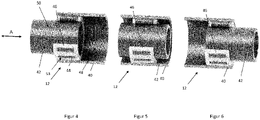
- Figures 4 to 6 show partially sectioned, perspective views of the threaded spindle drive 12 in different states.
- the threaded spindle drive 12 has an outer threaded spindle part 40 in which the inner threaded spindle part 42 can be displaced by means of bearing rollers 44, one of which is shown in FIG figure 4 is provided with a reference number, is stored.
- the two threaded spindle parts 40, 42 are cylindrical or at least essentially cylindrical.
- the outer lead screw part 40 and the inner lead screw part 42 are formed from a metal.
- the inner threaded spindle part 42 can be moved along an axial direction A of the threaded spindle drive 12, in particular along its longitudinal direction.
- the outer threaded spindle part 40 has an internal thread 48 and the inner threaded spindle part 42 has an external thread 50 .
- the internal thread 48 and the external thread 50 are only in figure 4 marked with a reference number.
- the threads 48, 50 are matched to one another. In particular, their gradients correspond.
- the threads 48, 50 can preferably have pitch angles in the range from 0.4 to 4°, for example 2°.
- the bearing rollers 44 are in the form of rods, in particular in the form of solid cylinders. Their diameters preferably correspond essentially to half the difference between the diameters of the two threaded spindle parts 40, 42 4 a groove 53 is marked as an example. The grooves 53 run parallel to one another. Their distance from one another is matched to the threads 48, 50.
- the bearing rollers 44 are arranged in a cage 46 .
- the cage 46 is made of a plastic, alternatively it can also be made of a metal.
- the outer threaded spindle part 40 is attached to the housing section 52 (see figure 3 ) non-rotatable and non-displaceable. The outer threaded spindle part 40 is thus stationary relative to the rest of the machine tool 1 (see also figure 3 ).
- a rotation of the inner threaded spindle part 42 relative to the outer threaded spindle part 40 leads to a translation of the inner threaded spindle part 42 along the axial direction A relative to the outer threaded spindle part 40, which is stationary relative to the rest of the machine tool 1.
- the cage 46 also moves together with the bearing rollers 44 within the outer threaded spindle part 40 with.
- the inner threaded spindle part 42 is displaced along the axial direction A at twice the speed as the cage 46 or the bearing rollers 44.
- the amplitude range of the displacement movement of the inner threaded spindle part 42 is twice as large as that of the cage 46 or the bearing rollers 44.
- the outer threaded spindle part 40 is twice as long as the cage 46.
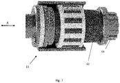
- figure 7 shows the threaded spindle drive 12 in a perspective, partially sectioned view. It can be seen in particular that the inner threaded spindle part 42 at one end, in particular at that of the output shaft 11 ( figure 3 ) end facing, a splined shaft portion 64 for connection to the shaft portion 60 ( figure 3 ) having.
- the threaded spindle drive 12, in particular in connection with the drive 8, can be set up to exert a maximum shearing pressure in the range from 7 N/mm 2 to 14 N/mm 2 , preferably 14 N/mm 2 , on the linear actuator 13 .
- it can be set up to drive the linear actuator at a maximum peripheral speed in the range from 5 m/s to 100 m/s, in particular 60 m/s.
Landscapes
- Engineering & Computer Science (AREA)
- Mechanical Engineering (AREA)
- Retarders (AREA)
- Transmission Devices (AREA)
Abstract
Description
- Die Erfindung betrifft eine Werkzeugmaschine, insbesondere eine Rohrpresse, enthaltend einen Antrieb, eine Abtriebswelle, einen Gewindespindeltrieb und einen Linearaktuator, wobei ein von dem Antrieb erzeugtes Drehmoment über die Abtriebswelle und den mit der Abtriebswelle verbundenen Gewindespindeltrieb auf den Linearaktuator übertragbar ist.
- Aus dem Stand der Technik sind unterschiedliche Werkzeugmaschinen für Umform- und Schneideprozesse bekannt. Mit Hilfe dieser speziellen Werkzeugmaschinen können beispielsweise Armierungseisen durchtrennt, Rohre mechanisch verbunden oder Schlauchschellen aufgepresst werden. Zu den Aufgaben des mechanischen Verbindens gehört auch das sogenannte Crimpen, Bördeln und Quetschen.
- Um die erforderlichen hohen Presskräfte für beispielsweise das Crimpen von Stahlrohren zu realisieren, verfügen die am Markt erhältlichen Umformmaschinen einen von einem Presszylinder angetriebenen Presskopf. Häufig wird dabei der Presszylinder zum Bewegen des Presskopfs hydraulisch angetrieben. Ein Elektromotor treibt wiederum eine Hydraulikpumpe an, welche die Linearbewegung des Presszylinders abtreibt. Alternativ sind auch mechanische Press-/Schneide- und Crimpwerkzeugmaschinen bekannt, welche statt der Hydraulik den Pressdruck über einen Gewindespindeltrieb in Kombination mit einem Elektromotor erzeugen. Hierbei wird die Rotationsbewegung des Elektromotors über eine Gewindespindel in eine lineare Bewegung transformiert. Häufig enthalten diese Werkzeugmaschine ein zwischen Spindel und Elektromotor geschaltetes Getriebe zur Reduktion des erforderlichen Motordrehmoments und um dadurch den Motor kleiner dimensionieren zu können.
- Die aus dem Stand der Technik bekannten Werkzeugmaschinen mit hydraulisch angetriebenen Linearaktuator neigen jedoch in der Entwicklung zu komplex sowie in der Handhabung zu groß bzw. zu lang, ineffizient und zu schwer zu sein. Des Weiteren benötigen die aus dem Stand der Technik bekannten Werkzeugmaschinen mit hydraulisch angetriebenen Linearaktuator relativ lang für einen einzigen Arbeitszyklus, wobei ein Arbeitszyklus beispielsweise ein Umform- bzw. Schneidezyklus sein kann.
- Die bisher bei derartigen Werkzeugmaschinen vorgesehenen Gewindespindeltriebe führen zudem zu hohen Reibungsverlusten. Versuche, diese Reibungsverluste zu minimieren, führten bislang ferner zu sehr aufwändigen und damit kostenintensiven Konstruktionen.
- Aufgabe der vorliegenden Erfindung ist es daher, eine Werkzeugmaschine der eingangs beschriebenen Art anzubieten, die besonders kostengünstig ist und eine hohe Effizienz bei dennoch sehr hoher Lasttragfähigkeit bietet.
- Die Aufgabe wird gelöst durch eine Werkzeugmaschine, insbesondere eine Rohrpresse, enthaltend einen Antrieb, eine Abtriebswelle, einen Gewindespindeltrieb und einen Linearaktuator, wobei ein von dem Antrieb erzeugtes Drehmoment über die Abtriebswelle und den mit der Abtriebswelle verbundenen Gewindespindeltrieb auf den Linearaktuator übertragbar ist, wobei der Gewindespindeltrieb ein inneres Gewindespindelteil mit einem Außengewinde und ein äußeres Gewindespindelteil mit einem Innengewinde aufweist, wobei das Innengewinde mit dem Außengewinde über wenigstens eine Lagerrolle zusammenwirkt und die wenigstens eine Lagerrolle wenigstens eine radial umlaufende Rille aufweist, mit der die Lagerrolle jeweils in das Außengewinde und in das Innengewinde eingreift.
- Erfindungsgemäß weist die wenigstens eine Lagerrolle ein oder mehrere radial umlaufende Rillen auf. Durch die wenigstens eine Rille ist somit an der Lagerrolle kein Schraubgewinde ausgebildet. Die Lagerrolle ist somit konstruktiv sehr einfach gehalten und dementsprechend kostengünstig herstellbar. Bei Relativrotation des inneren Gewindespindelteils relativ zum äußeren Gewindespindelteil kann die Lagerrolle am Innen- und am Außengewinde abrollen. Die Lagerrolle bildet somit ein Rollenlager, das gegenüber beispielsweise einer Gleitreibung eine besonders geringe Rollreibung aufweisen kann. Der Gewindespindeltrieb kann somit zur Umsetzung der Drehbewegung in eine Translation, insbesondere parallel zu einer Axialrichtung des Gewindespindeltriebs, lediglich geringe Reibungsverluste und damit eine besonders günstige Effizienz aufweisen. Je mehr radial umlaufende Rillen die Lagerrolle aufweist, desto höhere Lasten können entlang der Axialrichtung des Gewindespindeltriebs übertragen und/oder erzeugt werden.
- Die Werkzeugmaschine kann vorzugsweise eine mobile Werkzeugmaschine, beispielsweise eine Handwerkzeugmaschine oder ein mobiler Bauroboter, insbesondere für Arbeiten im Hochbau und/oder im Tiefbau, beispielsweise für Installationsarbeiten, sein. Die Werkzeugmaschine kann eine Pressvorrichtung, eine Trennvorrichtung, beispielsweise eine Trennschere, und/oder eine Crimpvorrichtung sein.
- Bevorzugte Ausführungsformen der Erfindung können mehrere Lagerrollen, insbesondere 3, 4, 6, 8, 10 , 12 oder 13 Lagerrollen, aufweisen. Die Lagerrollen können gleichmäßig über den Umfang des inneren Gewindespindelteils verteilt angeordnet sein.
- Vorzugsweise sind das Innengewinde und/oder das Außengewinde eingängig.
- Eine einfache Montage, insbesondere eine Teilvormontage, ist möglich, wenn die wenigstens eine Lagerrolle in einem Käfig aufgenommen ist. Wenn mehrere Lagerrollen vorgesehen sind, kann ein Käfig eine gleichmäßig entlang des Umfangs des inneren Gewindespindelteils verteilte Anordnung der Lagerrollen besonders erleichtern.
- Der Käfig und/oder die Laufrollen können einen Translationsfreiheitsgrad, insbesondere parallel zur Axialrichtung, relativ zum übrigen Gewindespindeltrieb aufweisen. Eine Translation des Käfigs und/oder der Laufrollen kann somit insbesondere parallel zur Längsachse des Gewindespindeltriebs möglich sein. Insbesondere kann es eingerichtet sein, dass sich bei Relativrotation des inneren Gewindespindelteils relativ zum äußeren Gewindespindelteil der Käfig mitsamt den Laufrollen, beziehungsweise im Falle eines Verzichts auf einen Käfig die Laufrollen allein, entlang der Axialrichtung relativ zum inneren Gewindespindelteil und/oder relativ zum äußeren Gewindespindelteil verlagert bzw. verlagern.
- Das äußere Gewindespindelteil kann relativ zu einem Gehäuse der Werkzeugmaschine drehfest und / oder verschiebungsfest festgelegt sein. Die Relativrotation kann somit zu einer Translation des inneren Gewindespindelteils relativ zum Gehäuse führen.
- Ist das innere Gewindespindelteil mit dem Linearaktuator verbunden, kann der Linearaktuator durch das innere Gewindespindelteil, insbesondere durch die Relativrotation, betätigbar sein und/oder betätigt werden.
- Auch kann das äußere Gewindespindelteil länger als die wenigstens eine Lagerrolle sein. Alternativ oder ergänzend kann das äußere Gewindespindelteil länger als der Käfig sein. Somit können die Lagerrollen und/oder, sofern vorhanden, der Käfig zumindest über eine gewisse Strecke hinweg in der Axialrichtung verlagert werden ohne den Bereich des äußeren Gewindespindelteils zu verlassen. Besonders bevorzugt kann dazu das äußere Gewindespindelteil wenigstens doppelt so lang sein wie die wenigstens eine Lagerrolle und/oder, sofern vorhanden, der Käfig sein.
- Bei einer Klasse von Ausführungsformen der Erfindung ist der Linearaktuator entlang der Längsachse des inneren Gewindespindelteils drehbar am inneren Gewindespindelteil gelagert, sodass der Linearaktuator von Rotationen des inneren Gewindespindelteils, insbesondere relativ zum Gehäuse, entkoppelbar und/oder entkoppelt ist. Dazu kann zwischen dem inneren Gewindespindelteil und dem Linearaktuator ein Kugellager und/oder ein Rollenlager angeordnet sein.
- Bei besonders bevorzugten Ausgestaltungen der Erfindung kann der Gewindespindeltrieb, vorzugsweise das innere Gewindespindelteil, vom Antrieb über eine teleskopierbare Wellenvorrichtung antreibbar sein, sodass das Drehmoment vom Antrieb auch bei einer Translation des inneren Gewindespindelteils in Axialrichtung auf den Gewindespindeltrieb, insbesondere auf das innere Gewindespindelteil, übertragbar ist. Die Abtriebswelle kann als teleskopierbare Wellenvorrichtung ausgebildet sein. Alternativ oder ergänzend kann die teleskopierbare Wellenvorrichtung als Teil der Abtriebswelle ausgebildet sein. Die teleskopierbare Wellenvorrichtung kann ein mit ein oder mehreren Längsnuten versehenes Nutenelement aufweisen, an dem vorzugsweise ein Passstück geführt sein kann.
- Ist der Antrieb als bürstenloser Motor ausgebildet, kann die Werkzeugmaschine eine besonders hohe Lebensdauer aufweisen, was wiederum über die Lebensdauer hinweg betrachtet, die Kosteneffizienz der Werkzeugmaschine verbessern kann.
- Das Drehmoment kann über eine Getriebevorrichtung, insbesondere über ein Untersetzungsgetriebe, besonders bevorzugt über eine Exzentergetriebevorrichtung, auf den Gewindespindeltrieb übertragbar sein und/oder übertragen werden. Bevorzugt kann eine Untersetzung um einen Faktor im Bereich von 10 bis 1000, insbesondere im Bereich von 10 bis 100, beispielsweise 20, vorgesehen sein.
- So kann die Werkzeugmaschine eine Exzentergetriebevorrichtung für eine Drehmomentanpassung zwischen dem Antrieb und dem Gewindespindeltrieb enthalten, wobei die Exzentergetriebevorrichtung ein von dem Antrieb antreibbaren Antriebsexzenter, ein von dem Antriebexzenter antreibbares Exzenterzahnrad, eine von dem Exzenterzahnrad antreibbare Ausgleichskupplung zur Drehmomentübertragung von dem Exzenterzahnrad auf die Abtriebswelle enthält.
- Für weitere Details zu möglichen Ausgestaltungen der Exzentergetriebevorrichtung wird ausdrücklich auf die europäische Patentanmeldung Aktenzeichen
EP20210196 - Weitere Vorteile ergeben sich auch aus der folgenden Figurenbeschreibung.
- In den Figuren sind verschiedene Ausführungsbeispiele der vorliegenden Erfindung dargestellt.
- Die Figuren, die Beschreibung und die Patentansprüche enthalten zahlreiche Merkmale in Kombination. Der Fachmann wird die Merkmale zweckmässigerweise auch einzeln betrachten und zu sinnvollen weiteren Kombinationen zusammenfassen.
- In den Figuren sind gleiche und gleichartige Komponenten und Baugruppen mit gleichen Bezugszeichen beziffert.
- Es zeigen:
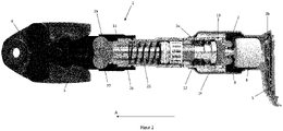
- Figur 1
- eine seitliche Ansicht auf eine Werkzeugmaschine in Ausgestaltung einer Rohrpresse;
- Figur 2
- eine seitliche Schnittansicht auf die beispielhaft als Rohrpresse ausgestaltete Werkzeugmaschine mit einem Antrieb, einer Abtriebswelle, einem Gewindespindeltrieb, einem Linearaktuator und einer Exzentergetriebevorrichtung;
- Figur 3
- eine perspektivische Schnittansicht auf die beispielhaft als Rohrpresse ausgestaltete Werkzeugmaschine mit dem Antrieb, der Abtriebswelle, dem Gewindespindeltrieb, dem Linearaktuator und der Exzentergetriebevorrichtung;
- Figur 4 bis Figur 6
- perspektivische Schnittansichten auf den Gewindespindeltrieb mit einem inneren Gewindespindelteil, einem äußeren Gewindespindelteil und einem Käfig mit Lagerrollen in unterschiedlichen Zuständen und
- Figur 7
- eine perspektivische Schnittansicht des Gewindespindeltriebs.
- In
Figur 1 bis 3 ist eine erfindungsgemäße Werkzeugmaschine 1 in einer beispielhaften Ausgestaltung als Rohrpresse gezeigt. Anstelle der Ausgestaltung als Rohrpresse kann die Werkzeugmaschine 1 auch als jedes andere Schneid- oder Umformwerkzeug ausgestaltet sein. So ist es insbesondere auch möglich, dass die erfindungsgemäße Werkzeugmaschine 1 als Auspressgerät für chemische Substanzen, wie z.B. Klebstoff oder Dübelmasse ausgestaltet ist. Derartige Auspressgeräte können auch als Dispenser bezeichnet werden. - Wie in
Figur 1 zu erkennen ist, weist die als Rohrpresse ausgestaltete Werkzeugmaschine 1 im Wesentlichen ein Gehäuse 2, eine Werkzeugaufnahme 3 und eine Energieversorgung 4 auf. - Das Gehäuse 2 der Werkzeugmaschine 1 ist im Wesentlichen zylindrisch ausgestaltet und enthält ein vorderes Ende 2a, ein hinteres Ende 2b, eine linke Seitenfläche 2c, eine rechte Seitenfläche 2d, eine Oberseite 2e und eine Unterseite 2f. Ein mittlerer Anteil 2g des Gehäuses 2 dient als Handgriff zum Halten bzw. Führen der Werkzeugmaschine 1. In den
Figuren 1 bis 3 ist lediglich die linke Seitenfläche 2c dargestellt. Das Gehäuse 2 geht in einen, vorzugsweise metallischen, Gehäuseabschnitt 52 über. - An dem hinteren Ende 2b des Gehäuses 2 der Werkzeugmaschine 1 ist die Energieversorgung 4 positioniert. Im vorliegenden Ausführungsbeispiel ist die Energieversorgung 4 als Akkumulator (auch Akku oder Batterie genannt), vorzugsweise als Lithium-basierterAkkumulator, ausgestaltet. Die als Akkumulator ausgestaltete Energieversorgung 4 kann wiederlösbar über eine Schnittstelle 5 mit dem hinteren Ende 2b des Gehäuses 2 der Werkzeugmaschine 1 verbunden werden. Mit Hilfe des Akkumulators 4 wird die Werkzeugmaschine 1 bzw. die elektrischen Verbraucher der Werkzeugmaschine 1 mit elektrischer Energie versorgt.
- Gemäß einer alternativen Ausgestaltung der vorliegenden Erfindung kann die Energieversorgung 4 der Werkzeugmaschine 1 auch als Stromkabel ausgestaltet sein zum Verbinden der Werkzeugmaschine 1 mit einer Stromnetzquelle (d.h. Steckdose).
- An dem vorderen Ende 2a des Gehäuses 2 der Werkzeugmaschine 1 ist die Werkzeugaufnahme 3 positioniert zum wiederlösbaren Aufnehmen und Halten eines Werkzeugs 6. An der Werkzeugaufnahme 3 ist in dem vorliegenden Ausführungsbeispiel ein Werkzeug 6 in Form eines Umformwerkzeugs positioniert. Das Umformwerkzeug 6 ist im vorliegenden Ausführungsbeispiel als sogenannter Presskopf ausgestaltet. Das als Presskopf ausgestaltete Umformwerkzeug 6 dient im Wesentlichen zum Bearbeiten und insbesondere Umformen von Leitungen, d.h. Rohre und Röhren. Die Leitungen sind in den Figuren nicht gezeigt.
- An der Unterseite 2f des Gehäuses 2 der Werkzeugmaschine 1 ist ein Aktivierungsschalter 7 positioniert. Mit Hilfe des Aktivierungsschalters 7 kann die Werkzeugmaschine 1 gestartet und gestoppt werden.
- Im Inneren des Gehäuses 2 der Werkzeugmaschine 1 ist im Wesentlichen ein Antrieb 8, eine Antriebswelle 9, eine Exzentergetriebevorrichtung 10, eine Abtriebswelle 11, ein Gewindespindeltrieb 12 und ein Linearaktuator 13 positioniert. Der Antrieb 8 ist in dem vorliegenden Ausführungsbeispiel als bürstenloser Elektromotor ausgestaltet.
- Wie beispielsweise aus den
Figuren 2 und3 ersichtlich ist, ist der als bürstenloser Elektromotor ausgestaltete Antrieb 8 über die Antriebswelle 9 mit der Exzentergetriebevorrichtung 10 verbunden. Durch die Verbindung mit der Antriebswelle 9 wird ein in dem Antrieb 8 erzeugtes Drehmoment von dem Antrieb 8 auf die Exzentergetriebevorrichtung 10 übertragen. - Mit Hilfe der Exzentergetriebevorrichtung 10 kann eine Drehzahlübersetzung vom Antrieb 8 auf die Abtriebswelle 11 erzeugt werden.
- Die Abtriebswelle 11 grenzt an den Gewindespindeltrieb 12 an. Der Gewindespindeltrieb 12 ist mit der Abtriebswelle 11 verbunden. Durch den Gewindespindeltrieb 12 kann die Drehbewegung der Abtriebswelle 11 in eine Linearbewegung umgewandelt werden.
- Die Abtriebswelle 11 ist als teleskopierbare Wellenvorrichtung ausgebildet. Sie ist somit längenveränderlich. Dazu weist sie ein mit ein oder mehreren Längsnuten versehenes Nutenelement 54 auf, an dem ein Passstück 56 axial verschiebbar geführt ist. In der Schnittdarstellung gemäß
Figur 3 ist dazu beispielhaft eine der Längsnuten 58 zu erkennen. Das Nutenelement 54 wird von der Exzentergetriebevorrichtung 10 rotatorisch angetrieben, wodurch wiederum das im Nutenelement 54 geführte Passstück 56 mitgenommen und damit angetrieben wird. Das Passstück 56 ist wiederum über einen axial angeordneten Wellenabschnitt 60 drehfest, insbesondere über eine Keilwellenverbindung, mit einem Teil des Gewindespindeltriebs 12 verbunden.
Wie denFiguren 2 und3 entnommen werden kann, ist der Gewindespindeltrieb 12 mit dem Linearaktuator 13, insbesondere mittels eines noch näher zu erläuternden inneren Gewindespindelteils 42 und einem Kugellager 62, verbunden. Durch das Kugellager 62 ist der Linearaktuator 13 rotatorisch vom Gewindespindeltrieb 12 und damit auch von der Abtriebswelle 11 entkoppelt, sodass er rein translatorische Bewegungen ausführen kann. - Der Linearaktuator 13 enthält im Wesentlichen eine Druckfeder 25 sowie eine Schubstange 26. Die Druckfeder 25 agiert dabei als Rückstellfeder für den Linearaktuator 13.
- An dem Linearaktuator 13 ist eine Kraftflussumlenkungseinrichtung 27 vorgesehen. Mit Hilfe des Linearaktuators 13 und der Kraftflussumlenkungseinrichtung 27 wird die lineare Kraft des Linearaktuators 13 so auf die Werkzeugaufnahme 3 übertragen, dass das als Presskopf ausgestaltete Werkzeug 6 zwischen einer geöffneten und geschlossenen Position bewegt werden kann.
- Der als Elektromotor ausgestaltete Antrieb 8 kann eingerichtet sein, sich bei einer maximalen Ausfahr- und Einfahrgeschwindigkeit des Linearaktuators 13 mit einem Drehzahlwert zwischen 10.000 und 30.000 rpm zu drehen. Insbesondere ist ein Drehzahlwert zwischen 15.000 bis 25.000 rpm für den Antrieb 8 vorgesehen.
-
Figuren 4 bis 6 zeigen teilgeschnittene, perspektivische Ansichten des Gewindespindeltriebs 12 in verschiedenen Zuständen. - Der Gewindespindeltrieb 12 weist ein äußeres Gewindespindelteil 40 auf, in dem das innere Gewindespindelteil 42 verschieblich mittels Lagerrollen 44, von denen eine beispielhaft in
Figur 4 mit einem Bezugszeichen versehen ist, gelagert ist. Die beiden Gewindespindelteile 40, 42 sind zylinderförmig oder zumindest im Wesentlichen zylinderförmig ausgebildet. Das äußere Gewindespindelteil 40 und das innere Gewindespindelteil 42 sind aus einem Metall ausgebildet. - Wie noch im Detail erläutert wird, ist das innere Gewindespindelteil 42 entlang einer Axialrichtung A des Gewindespindeltriebs 12, insbesondere entlang seiner Längsrichtung, bewegbar.
- Dazu weisen das äußere Gewindespindelteil 40 ein Innengewinde 48 und das innere Gewindespindelteil 42 ein Außengewinde 50 auf. Zur Vereinfachung der Darstellung sind das Innengewinde 48 und das Außengewinde 50 lediglich in
Figur 4 mit einem Bezugszeichen markiert. Die Gewinde 48, 50 sind aufeinander abgestimmt. Insbesondere entsprechen sich ihre Steigungen. Die Gewinde 48, 50 können vorzugsweise Steigungswinkel im Bereich von 0,4 bis 4 °, beispielsweise 2°, aufweisen. - Die Lagerrollen 44 sind stabförmig, insbesondere vollzylinderförmig, ausgebildet. Ihre Durchmesser entsprechen vorzugsweise im Wesentlichen der halben Differenz der Durchmesser der beiden Gewindespindelteile 40, 42. Die Lagerrollen 44 weisen umfangsseitig eine Vielzahl von umlaufenden, geschlossenen Rillen auf, von denen in
Fig. 4 beispielhaft eine Rille 53 markiert ist. Die Rillen 53 verlaufen parallel zueinander. Ihr Abstand voneinander ist auf die Gewinde 48, 50 abgestimmt. - Die Lagerrollen 44 sind in einem Käfig 46 angeordnet. Der Käfig 46 ist aus einem Kunststoff ausgebildet, alternativ kann er auch aus einem Metall ausgebildet sein.
- Das äußere Gewindespindelteil 40 ist am Gehäuseabschnitt 52 (siehe
Figur 3 ) drehfest und verschiebungsfest festgelegt. Das äußere Gewindespindelteil 40 ist somit ortsfest relativ zur übrigen Werkzeugmaschine 1 (siehe auchFigur 3 ). - Wie aus der Zusammenschau der
Figuren 4 bis 6 ersichtlich ist, führt eine Rotation des inneren Gewindespindelteils 42 relativ zum äußeren Gewindespindelteil 40 zu einer Translation des inneren Gewindespindelteils 42 entlang der Axialrichtung A relativ zum relativ zur übrigen Werkzeugmaschine 1 ortsfesten äußeren Gewindespindelteil 40. Während der Rotation wandert dabei auch der Käfig 46 mitsamt den Lagerrollen 44 innerhalb des äußeren Gewindespindelteils 40 mit. Insbesondere wird das innere Gewindespindelteil 42 mit der doppelten Geschwindigkeit entlang der Axialrichtung A verlagert wie der Käfig 46 bzw. die Lagerrollen 44. Dementsprechend ist auch der Amplitudenhub der Verlagerungsbewegung des inneren Gewindespindelteils 42 doppelt so groß wie der des Käfigs 46 bzw. der Lagerrollen 44. Um trotz eines ausreichenden Amplitudenhubs des inneren Gewindespindelteils 42 sicherzustellen, dass sich der Käfig 46 und die Lagerrollen 44 stets innerhalb des äußeren Gewindespindelteile 40 bewegen und somit eine optimale Lastübertragung sichergestellt bleibt, ist das äußere Gewindespindelteil 40 doppelt so lang wie der Käfig 46. -
Figur 7 zeigt den Gewindespindeltrieb 12 in einer perspektivischen, teilgeschnittenen Ansicht. Zu erkennen ist dabei insbesondere, dass das innere Gewindespindelteil 42 einenends, insbesondere an dem der Abtriebswelle 11 (Figur 3 ) zugewandten Ende, einen Keilwellenabschnitt 64 zur Verbindung mit dem Wellenabschnitt 60 (Figur 3 ) aufweist. - Aus der Zusammenschau der
Figuren 3 und7 ergibt sich somit, dass die rotierende Abtriebswelle 11 das innere Gewindespindelteil 42 in Rotation versetzt, wodurch sich letzteres je nach Drehrichtung nach vorne, also in Richtung des Werkzeugs 6 (Figur 3 ), oder nach hinten, also in Richtung des Antriebs 8 (Figur 3 ) entlang der Axialrichtung A verlagert. Hierdurch wiederum wird der Linearaktuator 13 (Figur 3 ) betätigt, sodass sich je nach Drehrichtung das beispielsweise als Umformwerkzeug ausgebildete Werkzeug 6 öffnet oder schließt bzw. einen Anpressdruck erhöht oder reduziert. - Der Gewindespindeltrieb 12, insbesondere in Verbindung mit dem Antrieb 8, kann eingerichtet sein, auf den Linearaktuator 13 einen maximalen Scherdruck im Bereich von 7 N/mm2 bis 14 N/mm2, vorzugsweise 14 N/mm2, auszuüben. Er kann alternativ oder ergänzend eingerichtet sein, den Linearaktuator mit einer maximalen Umfangsgeschwindigkeit im Bereich von 5 m/s bis zu 100 m/s, insbesondere 60 m/s, anzutreiben.
-
- 1
- Werkzeugmaschine
- 2
- Gehäuse
- 2a
- vorderes Ende 2a des Gehäuses
- 2b
- hinteres Ende des Gehäuses
- 2c
- linke Seitenfläche des Gehäuses
- 2d
- rechte Seitenfläche des Gehäuses
- 2e
- Oberseite des Gehäuses
- 2f
- Unterseite des Gehäuses
- 3
- Werkzeugaufnahme
- 4
- Energieversorgung
- 5
- Schnittstelle
- 6
- Werkzeug
- 7
- Aktivierungsschalter
- 8
- Antrieb
- 9
- Antriebswelle
- 10
- Exzentergetriebevorrichtung
- 11
- Abtriebswelle
- 12
- Gewindespindeltrieb
- 13
- Linearaktuator
- 25
- Druckfeder
- 26
- Schubstange
- 27
- Kraftflussumlenkungseinrichtung
- 30
- Lager
- 40
- äußeres Gewindespindelteil
- 42
- inneres Gewindespindelteil
- 44
- Lagerrolle
- 46
- Käfig
- 48
- Innengewinde
- 50
- Außengewinde
- 52
- Gehäuseabschnitt
- 53
- Rille
- 54
- Nutenelement
- 56
- Passstück
- 58
- Längsnute
- 60
- Wellenabschnitt
- 62
- Kugellager
- 64
- Keilwellenabschnitt
- A
- Axialrichtung
- DA
- Durchmesser einer Aussparung
- DK
- Durchmesser eines Kupplungselements
- DH
- Innendurchmesser des Hohlzahnrads
- E
- Exzentrizität des Exzenterzahnrads
Claims (10)
- Werkzeugmaschine (1), insbesondere eine Rohrpresse, enthaltend einen Antrieb (8), eine Abtriebswelle (11), einen Gewindespindeltrieb (12) und einen Linearaktuator (13), wobei ein von dem Antrieb (8) erzeugtes Drehmoment über die Abtriebswelle (11) und den mit der Abtriebswelle (11) verbundenen Gewindespindeltrieb (12) auf den Linearaktuator (13) übertragbar ist,
dadurch gekennzeichnet,
dass der Gewindespindeltrieb (12) ein inneres Gewindespindelteil (42) mit einem Außengewinde (50) und ein äußeres Gewindespindelteil (40) mit einem Innengewinde (48) aufweist, wobei das Innengewinde (48) mit dem Außengewinde (50) über wenigstens eine Lagerrolle (44) zusammenwirkt und die wenigstens eine Lagerrolle (44) wenigstens eine radial umlaufende Rille (53) aufweist, mit der die Lagerrolle (44) jeweils in das Außengewinde (50) und in das Innengewinde (48) eingreift. - Werkzeugmaschine nach dem vorhergehenden Anspruch, dadurch gekennzeichnet, dass die wenigstens eine Lagerrolle (44) in einem Käfig (46) aufgenommen ist.
- Werkzeugmaschine nach einem der vorhergehenden Ansprüche, dadurch gekennzeichnet, dass der Käfig (46) und/oder die wenigstens eine Laufrolle (44) einen Translationsfreiheitsgrad relativ zum übrigen Gewindespindeltrieb (12) aufweisen.
- Werkzeugmaschine nach einem der vorhergehenden Ansprüche, dadurch gekennzeichnet, dass das äußere Gewindespindelteil (40) relativ zu einem Gehäuse (2) der Werkzeugmaschine (1) drehfest und / oder verschiebungsfest festgelegt ist.
- Werkzeugmaschine nach einem der vorhergehenden Ansprüche, dadurch gekennzeichnet, dass die Länge des äußeren Gewindespindelteils (40) länger als die wenigstens eine Lagerrolle (44) ist.
- Werkzeugmaschine nach einem der vorhergehenden Ansprüche, dadurch gekennzeichnet, dass die Länge des äußeren Gewindespindelteils (40) wenigstens doppelt so lang wie die kürzeste Lagerrolle (44) ist.
- Werkzeugmaschine nach einem der vorhergehenden Ansprüche, dadurch gekennzeichnet, dass der Linearaktuator (13) entlang der Längsachse des inneren Gewindespindelteils (42) drehbar am inneren Gewindespindelteil (42) gelagert ist.
- Werkzeugmaschine nach einem der vorhergehenden Ansprüche, dadurch gekennzeichnet, dass der Gewindespindeltrieb (12), vorzugsweise das innere Gewindespindelteil (42), vom Antrieb (8) über eine teleskopierbare Wellenvorrichtung antreibbar ist.
- Werkzeugmaschine nach einem der vorhergehenden Ansprüche, dadurch gekennzeichnet, dass der Antrieb (8) ein bürstenloser Motor ist.
- Werkzeugmaschine nach einem der vorhergehenden Ansprüche, dadurch gekennzeichnet, dass das Drehmoment über eine Getriebevorrichtung, insbesondere ein Untersetzungsgetriebe, besonders bevorzugt über eine Exzentergetriebevorrichtung (10), auf den Gewindespindeltrieb (12) übertragbar ist und/oder übertragen wird.
Priority Applications (4)
| Application Number | Priority Date | Filing Date | Title |
|---|---|---|---|
| US18/035,413 US12257676B2 (en) | 2020-11-27 | 2021-09-13 | Power tool with threaded spindle drive |
| CN202180073617.4A CN116507434A (zh) | 2020-11-27 | 2021-09-13 | 具有螺纹主轴驱动器的动力工具 |
| PCT/EP2021/075036 WO2022111875A1 (de) | 2020-11-27 | 2021-09-13 | Werkzeugmaschine mit gewindespindeltrieb |
| EP21778362.0A EP4251370A1 (de) | 2020-11-27 | 2021-09-13 | Werkzeugmaschine mit gewindespindeltrieb |
Applications Claiming Priority (1)
| Application Number | Priority Date | Filing Date | Title |
|---|---|---|---|
| EP20210196.0A EP4005733A1 (de) | 2020-11-27 | 2020-11-27 | Exzentergetriebe für eine werkzeugmaschine |
Publications (3)
| Publication Number | Publication Date |
|---|---|
| EP4005735A1 true EP4005735A1 (de) | 2022-06-01 |
| EP4005735B1 EP4005735B1 (de) | 2024-04-10 |
| EP4005735C0 EP4005735C0 (de) | 2024-04-10 |
Family
ID=73642594
Family Applications (4)
| Application Number | Title | Priority Date | Filing Date |
|---|---|---|---|
| EP20210196.0A Withdrawn EP4005733A1 (de) | 2020-11-27 | 2020-11-27 | Exzentergetriebe für eine werkzeugmaschine |
| EP21156580.9A Active EP4005735B1 (de) | 2020-11-27 | 2021-02-11 | Werkzeugmaschine mit gewindespindeltrieb |
| EP21778362.0A Pending EP4251370A1 (de) | 2020-11-27 | 2021-09-13 | Werkzeugmaschine mit gewindespindeltrieb |
| EP21810008.9A Active EP4251371B1 (de) | 2020-11-27 | 2021-11-10 | Exzentergetriebe für eine werkzeugmaschine |
Family Applications Before (1)
| Application Number | Title | Priority Date | Filing Date |
|---|---|---|---|
| EP20210196.0A Withdrawn EP4005733A1 (de) | 2020-11-27 | 2020-11-27 | Exzentergetriebe für eine werkzeugmaschine |
Family Applications After (2)
| Application Number | Title | Priority Date | Filing Date |
|---|---|---|---|
| EP21778362.0A Pending EP4251370A1 (de) | 2020-11-27 | 2021-09-13 | Werkzeugmaschine mit gewindespindeltrieb |
| EP21810008.9A Active EP4251371B1 (de) | 2020-11-27 | 2021-11-10 | Exzentergetriebe für eine werkzeugmaschine |
Country Status (4)
| Country | Link |
|---|---|
| US (2) | US12257676B2 (de) |
| EP (4) | EP4005733A1 (de) |
| CN (2) | CN116507434A (de) |
| WO (2) | WO2022111875A1 (de) |
Families Citing this family (5)
| Publication number | Priority date | Publication date | Assignee | Title |
|---|---|---|---|---|
| EP4005733A1 (de) | 2020-11-27 | 2022-06-01 | Hilti Aktiengesellschaft | Exzentergetriebe für eine werkzeugmaschine |
| EP4006382A1 (de) | 2020-11-30 | 2022-06-01 | Hilti Aktiengesellschaft | Federelement an kopplungsvorrichtung |
| USD1042068S1 (en) * | 2021-05-19 | 2024-09-17 | Gustav Klauke Gmbh | Hydraulic press tool |
| DE102022212148A1 (de) * | 2022-11-15 | 2024-05-16 | Mahle International Gmbh | Crimp-Werkzeug und damit hergestellter Wärmeübertrager |
| EP4530021A1 (de) * | 2023-09-28 | 2025-04-02 | Hilti Aktiengesellschaft | Mobile werkzeugmaschine mit einem einen anschlag aufweisenden gewindespindeltrieb |
Citations (3)
| Publication number | Priority date | Publication date | Assignee | Title |
|---|---|---|---|---|
| DE102018209819A1 (de) * | 2018-06-18 | 2019-12-19 | Zf Friedrichshafen Ag | Spindelantrieb für eine steer-by-wire-Lenkung sowie steer-by-wire-Lenkung |
| DE102018115788A1 (de) * | 2018-06-29 | 2020-01-02 | Schaeffler Technologies AG & Co. KG | Gewindetrieb und Linearaktuator mit diesem Gewindetrieb |
| DE102018124646A1 (de) * | 2018-10-05 | 2020-04-09 | Rothenberger Ag | Handwerkzeug zum umformenden und/oder trennenden Bearbeiten von Kunststoff- oder Metallwerkstücken, insbesondere Kunststoff- oder Metallrohren |
Family Cites Families (29)
| Publication number | Priority date | Publication date | Assignee | Title |
|---|---|---|---|---|
| US4799844A (en) * | 1988-01-11 | 1989-01-24 | Trw Inc | Elliptical thread design |
| US5195354A (en) * | 1989-03-31 | 1993-03-23 | Japan Storage Battery Co., Ltd. | Cam crank mechanism and motor driven hydraulic tool |
| US5511439A (en) | 1994-07-22 | 1996-04-30 | Las Navas Garcia; Jose M. | Pushing mechansim |
| NL1011731C2 (nl) | 1999-04-06 | 2000-10-09 | Skf Engineering & Res Services | Actuator met compacte tandwielreductie. |
| EP1055488B1 (de) | 1999-05-28 | 2007-08-08 | REMS-WERK Christian Föll und Söhne GmbH & Co | Vorrichtung zum Aufbringen einer Presskraft |
| DE10064901A1 (de) * | 2000-03-27 | 2001-10-04 | Continental Teves Ag & Co Ohg | Betätigungseinheit mit einem Gewindetrieb, einem Planetengetriebe und einem von diesen beeinflußten Betätigungselement |
| CN100404935C (zh) * | 2002-06-20 | 2008-07-23 | 株式会社开滋 | 用于阀门的致动器 |
| US20050103170A1 (en) | 2003-11-18 | 2005-05-19 | Norberto Del Rio | Hydroligripcut pliers |
| DE102006023535B4 (de) | 2006-05-19 | 2008-12-18 | Keiper Gmbh & Co.Kg | Getriebestufe für einen Stellantrieb |
| DE102009040460B4 (de) | 2009-09-01 | 2023-01-12 | Adient Us Llc | Antriebseinheit für einen Fahrzeugsitz, System und Fahrzeugsitz |
| DE202009015515U1 (de) * | 2009-11-17 | 2011-04-07 | Novopress Gmbh Pressen Und Presswerkzeuge & Co. Kommanditgesellschaft | Handgeführtes Pressgerät |
| DE202011101675U1 (de) | 2011-06-10 | 2012-09-13 | Novopress Gmbh Pressen Und Presswerkzeuge & Co. Kg | Elektrohydraulisches Pressgerät |
| FR3009902B1 (fr) * | 2013-08-20 | 2015-09-04 | Virax Sa | Dispositif de detection de presence d'un outil amovible d'un actionneur lineaire |
| FR3009905B1 (fr) * | 2013-08-20 | 2015-09-04 | Virax Sa | Dispositif de detection de butee arriere sur un actionneur lineaire |
| FR3010254B1 (fr) | 2013-08-27 | 2017-02-10 | Virax Sa | Actionneur lineaire a architecture en ligne |
| US9808851B2 (en) * | 2015-04-02 | 2017-11-07 | Milwaukee Electric Tool Corporation | PEX crimping tool |
| ITUA20161807A1 (it) * | 2016-03-18 | 2017-09-18 | Cembre Spa | Utensile oleodinamico di compressione o taglio |
| US10512964B2 (en) * | 2016-12-14 | 2019-12-24 | Ridge Tool Company | Electrically powered crimp tool |
| US10675805B2 (en) * | 2016-12-14 | 2020-06-09 | Ridge Tool Company | Electrically powered crimp tool and method of using |
| DE102018121971A1 (de) | 2018-09-10 | 2020-03-12 | Gustav Klauke Gmbh | Presswerkzeug |
| WO2020069696A1 (de) * | 2018-10-05 | 2020-04-09 | Rothenberger Ag | Handwerkzeug zum umformenden und/oder trennenden bearbeiten von kunststoff- oder metallwerkstücken, insbesondere kunststoff- oder metallrohren |
| EP3639941B1 (de) * | 2018-10-19 | 2026-03-18 | Emerson Professional Tools AG | Pressmaschine mit sensorsystem zur werkstück-identifikation |
| RU2018139004A (ru) * | 2018-11-06 | 2020-05-12 | Акционерное общество "Диаконт" | Линейный электромеханический привод c возможностью смазывания без демонтажа |
| EP3653341A1 (de) | 2018-11-13 | 2020-05-20 | Hilti Aktiengesellschaft | Handwerkzeugmaschine |
| KR102130846B1 (ko) | 2019-04-26 | 2020-07-03 | 주식회사평화발레오 | 회전 출력형 액추에이터 |
| US11236849B2 (en) * | 2019-09-04 | 2022-02-01 | Techtronic Cordless Gp | Pressing tool and method for a re-pressing operation |
| EP4005733A1 (de) * | 2020-11-27 | 2022-06-01 | Hilti Aktiengesellschaft | Exzentergetriebe für eine werkzeugmaschine |
| EP4006382A1 (de) | 2020-11-30 | 2022-06-01 | Hilti Aktiengesellschaft | Federelement an kopplungsvorrichtung |
| EP4005734A1 (de) | 2020-11-30 | 2022-06-01 | Hilti Aktiengesellschaft | Kopplungsmechanismus |
-
2020
- 2020-11-27 EP EP20210196.0A patent/EP4005733A1/de not_active Withdrawn
-
2021
- 2021-02-11 EP EP21156580.9A patent/EP4005735B1/de active Active
- 2021-09-13 US US18/035,413 patent/US12257676B2/en active Active
- 2021-09-13 EP EP21778362.0A patent/EP4251370A1/de active Pending
- 2021-09-13 WO PCT/EP2021/075036 patent/WO2022111875A1/de not_active Ceased
- 2021-09-13 CN CN202180073617.4A patent/CN116507434A/zh active Pending
- 2021-11-10 WO PCT/EP2021/081220 patent/WO2022111998A1/de not_active Ceased
- 2021-11-10 CN CN202180079187.7A patent/CN116490299A/zh active Pending
- 2021-11-10 US US18/037,255 patent/US12479073B2/en active Active
- 2021-11-10 EP EP21810008.9A patent/EP4251371B1/de active Active
Patent Citations (3)
| Publication number | Priority date | Publication date | Assignee | Title |
|---|---|---|---|---|
| DE102018209819A1 (de) * | 2018-06-18 | 2019-12-19 | Zf Friedrichshafen Ag | Spindelantrieb für eine steer-by-wire-Lenkung sowie steer-by-wire-Lenkung |
| DE102018115788A1 (de) * | 2018-06-29 | 2020-01-02 | Schaeffler Technologies AG & Co. KG | Gewindetrieb und Linearaktuator mit diesem Gewindetrieb |
| DE102018124646A1 (de) * | 2018-10-05 | 2020-04-09 | Rothenberger Ag | Handwerkzeug zum umformenden und/oder trennenden Bearbeiten von Kunststoff- oder Metallwerkstücken, insbesondere Kunststoff- oder Metallrohren |
Non-Patent Citations (1)
| Title |
|---|
| NN: "Spielfreier Rollgewindetrieb", F & M. FEINWERKTECHNIK MIKROTECHNIK MESSTECHNIK, HANSER, MUNCHEN, DE, vol. 103, no. 5, 1 May 1995 (1995-05-01), pages 255, XP002126235, ISSN: 0944-1018 * |
Also Published As
| Publication number | Publication date |
|---|---|
| CN116507434A (zh) | 2023-07-28 |
| US12479073B2 (en) | 2025-11-25 |
| WO2022111875A1 (de) | 2022-06-02 |
| CN116490299A (zh) | 2023-07-25 |
| EP4005733A1 (de) | 2022-06-01 |
| EP4251371A1 (de) | 2023-10-04 |
| EP4005735B1 (de) | 2024-04-10 |
| US20230415218A1 (en) | 2023-12-28 |
| EP4005735C0 (de) | 2024-04-10 |
| EP4251371B1 (de) | 2024-09-04 |
| US12257676B2 (en) | 2025-03-25 |
| US20230405779A1 (en) | 2023-12-21 |
| WO2022111998A1 (de) | 2022-06-02 |
| EP4251370A1 (de) | 2023-10-04 |
Similar Documents
| Publication | Publication Date | Title |
|---|---|---|
| EP4005735B1 (de) | Werkzeugmaschine mit gewindespindeltrieb | |
| EP4251903B1 (de) | Federelement an kopplungsvorrichtung | |
| EP4005734A1 (de) | Kopplungsmechanismus | |
| DE102017212823A1 (de) | Spindelantriebseinrichtung | |
| EP2138256B1 (de) | Einstellbarer Exzenterantrieb für eine Werkzeugmaschine, insbesondere zum Superfinishen oder Honen | |
| DE112018008218T5 (de) | Kompressions- oder Schneidwerkzeug | |
| DE10313739A1 (de) | Kupplungsbetätigungen | |
| DE10218112B4 (de) | Fahrzeugbremse | |
| EP3641983B1 (de) | Rundschalttisch mit kraft-optimiertem antrieb | |
| DE69422982T2 (de) | Rotationsschalter mit externen lagern | |
| EP1820600A1 (de) | Bohrspindel für Horizontal- oder Vertikalbearbeitungszentrum mit innenliegendem leistungsverzweigtem Antrieb | |
| DE102016219220B4 (de) | Hydraulikantrieb | |
| DE102018105537A1 (de) | Pressvorrichtung mit zwei Übersetzungsverhältnissen | |
| EP0903494A1 (de) | Haudraulikpumpe | |
| EP2186606B1 (de) | Vorsatzvorrichtung für eine Rohrpressmaschine | |
| DE102011084489A1 (de) | Vorrichtung zum Betreiben eines Presskolbens | |
| DE2703661A1 (de) | Mechanische transmission | |
| EP1225349B1 (de) | Fügeverfahren für eine Kugelgelenkverbindung | |
| EP4530021A1 (de) | Mobile werkzeugmaschine mit einem einen anschlag aufweisenden gewindespindeltrieb | |
| DE10252046B4 (de) | Antrieb für eine Spritzgiessmaschine | |
| DE202018101354U1 (de) | Pressvorrichtung mit zwei Übersetzungsverhältnissen | |
| EP4148298A1 (de) | Getriebevorrichtung für eine werkzeugmaschine | |
| EP4385665A1 (de) | Pressvorrichtung | |
| EP1559922B1 (de) | Kupplung | |
| EP4385664A1 (de) | Elektrohandwerkzeug und verfahren zum betreiben eines elektrohandwerkzeugs |
Legal Events
| Date | Code | Title | Description |
|---|---|---|---|
| PUAI | Public reference made under article 153(3) epc to a published international application that has entered the european phase |
Free format text: ORIGINAL CODE: 0009012 |
|
| STAA | Information on the status of an ep patent application or granted ep patent |
Free format text: STATUS: THE APPLICATION HAS BEEN PUBLISHED |
|
| AK | Designated contracting states |
Kind code of ref document: A1 Designated state(s): AL AT BE BG CH CY CZ DE DK EE ES FI FR GB GR HR HU IE IS IT LI LT LU LV MC MK MT NL NO PL PT RO RS SE SI SK SM TR |
|
| STAA | Information on the status of an ep patent application or granted ep patent |
Free format text: STATUS: REQUEST FOR EXAMINATION WAS MADE |
|
| 17P | Request for examination filed |
Effective date: 20221201 |
|
| RBV | Designated contracting states (corrected) |
Designated state(s): AL AT BE BG CH CY CZ DE DK EE ES FI FR GB GR HR HU IE IS IT LI LT LU LV MC MK MT NL NO PL PT RO RS SE SI SK SM TR |
|
| GRAP | Despatch of communication of intention to grant a patent |
Free format text: ORIGINAL CODE: EPIDOSNIGR1 |
|
| STAA | Information on the status of an ep patent application or granted ep patent |
Free format text: STATUS: GRANT OF PATENT IS INTENDED |
|
| RIC1 | Information provided on ipc code assigned before grant |
Ipc: H01R 43/042 20060101ALI20231219BHEP Ipc: B25B 25/00 20060101ALI20231219BHEP Ipc: B21D 39/04 20060101ALI20231219BHEP Ipc: B25B 27/10 20060101AFI20231219BHEP |
|
| INTG | Intention to grant announced |
Effective date: 20240116 |
|
| GRAS | Grant fee paid |
Free format text: ORIGINAL CODE: EPIDOSNIGR3 |
|
| GRAA | (expected) grant |
Free format text: ORIGINAL CODE: 0009210 |
|
| STAA | Information on the status of an ep patent application or granted ep patent |
Free format text: STATUS: THE PATENT HAS BEEN GRANTED |
|
| AK | Designated contracting states |
Kind code of ref document: B1 Designated state(s): AL AT BE BG CH CY CZ DE DK EE ES FI FR GB GR HR HU IE IS IT LI LT LU LV MC MK MT NL NO PL PT RO RS SE SI SK SM TR |
|
| REG | Reference to a national code |
Ref country code: GB Ref legal event code: FG4D Free format text: NOT ENGLISH |
|
| REG | Reference to a national code |
Ref country code: CH Ref legal event code: EP |
|
| REG | Reference to a national code |
Ref country code: DE Ref legal event code: R096 Ref document number: 502021003254 Country of ref document: DE |
|
| REG | Reference to a national code |
Ref country code: IE Ref legal event code: FG4D Free format text: LANGUAGE OF EP DOCUMENT: GERMAN |
|
| U01 | Request for unitary effect filed |
Effective date: 20240412 |
|
| U07 | Unitary effect registered |
Designated state(s): AT BE BG DE DK EE FI FR IT LT LU LV MT NL PT SE SI Effective date: 20240422 |
|
| PG25 | Lapsed in a contracting state [announced via postgrant information from national office to epo] |
Ref country code: IS Free format text: LAPSE BECAUSE OF FAILURE TO SUBMIT A TRANSLATION OF THE DESCRIPTION OR TO PAY THE FEE WITHIN THE PRESCRIBED TIME-LIMIT Effective date: 20240810 |
|
| PG25 | Lapsed in a contracting state [announced via postgrant information from national office to epo] |
Ref country code: HR Free format text: LAPSE BECAUSE OF FAILURE TO SUBMIT A TRANSLATION OF THE DESCRIPTION OR TO PAY THE FEE WITHIN THE PRESCRIBED TIME-LIMIT Effective date: 20240410 |
|
| PG25 | Lapsed in a contracting state [announced via postgrant information from national office to epo] |
Ref country code: GR Free format text: LAPSE BECAUSE OF FAILURE TO SUBMIT A TRANSLATION OF THE DESCRIPTION OR TO PAY THE FEE WITHIN THE PRESCRIBED TIME-LIMIT Effective date: 20240711 |
|
| PG25 | Lapsed in a contracting state [announced via postgrant information from national office to epo] |
Ref country code: ES Free format text: LAPSE BECAUSE OF FAILURE TO SUBMIT A TRANSLATION OF THE DESCRIPTION OR TO PAY THE FEE WITHIN THE PRESCRIBED TIME-LIMIT Effective date: 20240410 |
|
| PG25 | Lapsed in a contracting state [announced via postgrant information from national office to epo] |
Ref country code: PL Free format text: LAPSE BECAUSE OF FAILURE TO SUBMIT A TRANSLATION OF THE DESCRIPTION OR TO PAY THE FEE WITHIN THE PRESCRIBED TIME-LIMIT Effective date: 20240410 |
|
| PG25 | Lapsed in a contracting state [announced via postgrant information from national office to epo] |
Ref country code: PL Free format text: LAPSE BECAUSE OF FAILURE TO SUBMIT A TRANSLATION OF THE DESCRIPTION OR TO PAY THE FEE WITHIN THE PRESCRIBED TIME-LIMIT Effective date: 20240410 Ref country code: NO Free format text: LAPSE BECAUSE OF FAILURE TO SUBMIT A TRANSLATION OF THE DESCRIPTION OR TO PAY THE FEE WITHIN THE PRESCRIBED TIME-LIMIT Effective date: 20240710 Ref country code: IS Free format text: LAPSE BECAUSE OF FAILURE TO SUBMIT A TRANSLATION OF THE DESCRIPTION OR TO PAY THE FEE WITHIN THE PRESCRIBED TIME-LIMIT Effective date: 20240810 Ref country code: HR Free format text: LAPSE BECAUSE OF FAILURE TO SUBMIT A TRANSLATION OF THE DESCRIPTION OR TO PAY THE FEE WITHIN THE PRESCRIBED TIME-LIMIT Effective date: 20240410 Ref country code: GR Free format text: LAPSE BECAUSE OF FAILURE TO SUBMIT A TRANSLATION OF THE DESCRIPTION OR TO PAY THE FEE WITHIN THE PRESCRIBED TIME-LIMIT Effective date: 20240711 Ref country code: ES Free format text: LAPSE BECAUSE OF FAILURE TO SUBMIT A TRANSLATION OF THE DESCRIPTION OR TO PAY THE FEE WITHIN THE PRESCRIBED TIME-LIMIT Effective date: 20240410 Ref country code: RS Free format text: LAPSE BECAUSE OF FAILURE TO SUBMIT A TRANSLATION OF THE DESCRIPTION OR TO PAY THE FEE WITHIN THE PRESCRIBED TIME-LIMIT Effective date: 20240710 |
|
| REG | Reference to a national code |
Ref country code: DE Ref legal event code: R097 Ref document number: 502021003254 Country of ref document: DE |
|
| PG25 | Lapsed in a contracting state [announced via postgrant information from national office to epo] |
Ref country code: CZ Free format text: LAPSE BECAUSE OF FAILURE TO SUBMIT A TRANSLATION OF THE DESCRIPTION OR TO PAY THE FEE WITHIN THE PRESCRIBED TIME-LIMIT Effective date: 20240410 |
|
| PG25 | Lapsed in a contracting state [announced via postgrant information from national office to epo] |
Ref country code: RO Free format text: LAPSE BECAUSE OF FAILURE TO SUBMIT A TRANSLATION OF THE DESCRIPTION OR TO PAY THE FEE WITHIN THE PRESCRIBED TIME-LIMIT Effective date: 20240410 Ref country code: SK Free format text: LAPSE BECAUSE OF FAILURE TO SUBMIT A TRANSLATION OF THE DESCRIPTION OR TO PAY THE FEE WITHIN THE PRESCRIBED TIME-LIMIT Effective date: 20240410 |
|
| PG25 | Lapsed in a contracting state [announced via postgrant information from national office to epo] |
Ref country code: SM Free format text: LAPSE BECAUSE OF FAILURE TO SUBMIT A TRANSLATION OF THE DESCRIPTION OR TO PAY THE FEE WITHIN THE PRESCRIBED TIME-LIMIT Effective date: 20240410 |
|
| PG25 | Lapsed in a contracting state [announced via postgrant information from national office to epo] |
Ref country code: SM Free format text: LAPSE BECAUSE OF FAILURE TO SUBMIT A TRANSLATION OF THE DESCRIPTION OR TO PAY THE FEE WITHIN THE PRESCRIBED TIME-LIMIT Effective date: 20240410 Ref country code: SK Free format text: LAPSE BECAUSE OF FAILURE TO SUBMIT A TRANSLATION OF THE DESCRIPTION OR TO PAY THE FEE WITHIN THE PRESCRIBED TIME-LIMIT Effective date: 20240410 Ref country code: RO Free format text: LAPSE BECAUSE OF FAILURE TO SUBMIT A TRANSLATION OF THE DESCRIPTION OR TO PAY THE FEE WITHIN THE PRESCRIBED TIME-LIMIT Effective date: 20240410 Ref country code: CZ Free format text: LAPSE BECAUSE OF FAILURE TO SUBMIT A TRANSLATION OF THE DESCRIPTION OR TO PAY THE FEE WITHIN THE PRESCRIBED TIME-LIMIT Effective date: 20240410 |
|
| PLBE | No opposition filed within time limit |
Free format text: ORIGINAL CODE: 0009261 |
|
| STAA | Information on the status of an ep patent application or granted ep patent |
Free format text: STATUS: NO OPPOSITION FILED WITHIN TIME LIMIT |
|
| 26N | No opposition filed |
Effective date: 20250113 |
|
| U20 | Renewal fee for the european patent with unitary effect paid |
Year of fee payment: 5 Effective date: 20250221 |
|
| PG25 | Lapsed in a contracting state [announced via postgrant information from national office to epo] |
Ref country code: MC Free format text: LAPSE BECAUSE OF FAILURE TO SUBMIT A TRANSLATION OF THE DESCRIPTION OR TO PAY THE FEE WITHIN THE PRESCRIBED TIME-LIMIT Effective date: 20240410 |
|
| PG25 | Lapsed in a contracting state [announced via postgrant information from national office to epo] |
Ref country code: IE Free format text: LAPSE BECAUSE OF NON-PAYMENT OF DUE FEES Effective date: 20250211 |
|
| REG | Reference to a national code |
Ref country code: CH Ref legal event code: U11 Free format text: ST27 STATUS EVENT CODE: U-0-0-U10-U11 (AS PROVIDED BY THE NATIONAL OFFICE) Effective date: 20260301 |
|
| U20 | Renewal fee for the european patent with unitary effect paid |
Year of fee payment: 6 Effective date: 20260225 |
|
| PGFP | Annual fee paid to national office [announced via postgrant information from national office to epo] |
Ref country code: GB Payment date: 20260220 Year of fee payment: 6 |
|
| PGFP | Annual fee paid to national office [announced via postgrant information from national office to epo] |
Ref country code: CH Payment date: 20260301 Year of fee payment: 6 |