EP4005735A1 - Machine-outil pourvu d'arbre de sortie à vis - Google Patents
Machine-outil pourvu d'arbre de sortie à vis Download PDFInfo
- Publication number
- EP4005735A1 EP4005735A1 EP21156580.9A EP21156580A EP4005735A1 EP 4005735 A1 EP4005735 A1 EP 4005735A1 EP 21156580 A EP21156580 A EP 21156580A EP 4005735 A1 EP4005735 A1 EP 4005735A1
- Authority
- EP
- European Patent Office
- Prior art keywords
- threaded spindle
- machine tool
- drive
- spindle part
- tool according
- Prior art date
- Legal status (The legal status is an assumption and is not a legal conclusion. Google has not performed a legal analysis and makes no representation as to the accuracy of the status listed.)
- Granted
Links
Images


Classifications
-
- B—PERFORMING OPERATIONS; TRANSPORTING
- B25—HAND TOOLS; PORTABLE POWER-DRIVEN TOOLS; MANIPULATORS
- B25B—TOOLS OR BENCH DEVICES NOT OTHERWISE PROVIDED FOR, FOR FASTENING, CONNECTING, DISENGAGING, OR HOLDING
- B25B27/00—Hand tools, specially adapted for fitting together or separating parts or objects whether or not involving some deformation, not otherwise provided for
- B25B27/02—Hand tools, specially adapted for fitting together or separating parts or objects whether or not involving some deformation, not otherwise provided for for connecting objects by press fit or detaching same
- B25B27/10—Hand tools, specially adapted for fitting together or separating parts or objects whether or not involving some deformation, not otherwise provided for for connecting objects by press fit or detaching same inserting fittings into hoses
-
- B—PERFORMING OPERATIONS; TRANSPORTING
- B21—MECHANICAL METAL-WORKING WITHOUT ESSENTIALLY REMOVING MATERIAL; PUNCHING METAL
- B21D—WORKING OR PROCESSING OF SHEET METAL OR METAL TUBES, RODS OR PROFILES WITHOUT ESSENTIALLY REMOVING MATERIAL; PUNCHING METAL
- B21D39/00—Application of procedures in order to connect objects or parts, e.g. coating with sheet metal otherwise than by plating; Tube expanders
- B21D39/04—Application of procedures in order to connect objects or parts, e.g. coating with sheet metal otherwise than by plating; Tube expanders of tubes with tubes; of tubes with rods
- B21D39/046—Connecting tubes to tube-like fittings
-
- B—PERFORMING OPERATIONS; TRANSPORTING
- B21—MECHANICAL METAL-WORKING WITHOUT ESSENTIALLY REMOVING MATERIAL; PUNCHING METAL
- B21D—WORKING OR PROCESSING OF SHEET METAL OR METAL TUBES, RODS OR PROFILES WITHOUT ESSENTIALLY REMOVING MATERIAL; PUNCHING METAL
- B21D39/00—Application of procedures in order to connect objects or parts, e.g. coating with sheet metal otherwise than by plating; Tube expanders
- B21D39/04—Application of procedures in order to connect objects or parts, e.g. coating with sheet metal otherwise than by plating; Tube expanders of tubes with tubes; of tubes with rods
- B21D39/048—Application of procedures in order to connect objects or parts, e.g. coating with sheet metal otherwise than by plating; Tube expanders of tubes with tubes; of tubes with rods using presses for radially crimping tubular elements
-
- B—PERFORMING OPERATIONS; TRANSPORTING
- B25—HAND TOOLS; PORTABLE POWER-DRIVEN TOOLS; MANIPULATORS
- B25B—TOOLS OR BENCH DEVICES NOT OTHERWISE PROVIDED FOR, FOR FASTENING, CONNECTING, DISENGAGING, OR HOLDING
- B25B25/00—Implements for fastening, connecting or tensioning of wire or strip
- B25B25/005—Implements for fastening, connecting or tensioning of wire or strip for applying wire clasps to hose couplings
Definitions
- the invention relates to a machine tool, in particular a pipe press, containing a drive, an output shaft, a threaded spindle drive and a linear actuator, wherein a torque generated by the drive can be transmitted to the linear actuator via the output shaft and the threaded spindle drive connected to the output shaft.
- the forming machines available on the market have a press head driven by a press cylinder.
- the press cylinder for moving the press head is often driven hydraulically.
- An electric motor in turn drives a hydraulic pump, which drives the linear movement of the press cylinder.
- mechanical pressing/cutting and crimping machine tools are also known which, instead of hydraulics, generate the pressing pressure via a threaded spindle drive in combination with an electric motor.
- the rotary movement of the electric motor is transformed into a linear movement via a threaded spindle.
- These machine tools often contain a gearbox connected between the spindle and the electric motor in order to reduce the required motor torque and thereby allow the motor to be dimensioned smaller.
- machine tools known from the prior art with hydraulically driven linear actuators tend to be too complex to develop and to be too large or too long, inefficient and too heavy to handle.
- machine tools known from the prior art with hydraulically driven linear actuators require a relatively long time for a single work cycle, with a work cycle being able to be a forming or cutting cycle, for example.
- the object of the present invention is therefore to offer a machine tool of the type described at the outset that is particularly inexpensive and offers high efficiency with a very high load-carrying capacity.
- a machine tool in particular a pipe press, containing a drive, an output shaft, a threaded spindle drive and a linear actuator, wherein a torque generated by the drive can be transmitted to the linear actuator via the output shaft and the threaded spindle drive connected to the output shaft
- the Threaded spindle drive has an inner threaded spindle part with an external thread and an outer threaded spindle part with an internal thread, wherein the internal thread interacts with the external thread via at least one bearing roller and the at least one bearing roller has at least one radially circumferential groove, with which the bearing roller is inserted into the external thread and into the internal thread engages.
- the at least one bearing roller has one or more radially circumferential grooves.
- the at least one groove means that no screw thread is formed on the bearing roller.
- the bearing roller is therefore kept structurally very simple and can therefore be produced inexpensively.
- the bearing roller can roll on the internal and external threads.
- the bearing roller thus forms a roller bearing which can have particularly low rolling friction compared to, for example, sliding friction.
- the threaded spindle drive can thus have only low friction losses and thus a particularly favorable efficiency for converting the rotational movement into a translation, in particular parallel to an axial direction of the threaded spindle drive.
- the more radially circumferential grooves the bearing roller has, the higher loads can be transmitted and/or generated along the axial direction of the threaded spindle drive.
- the machine tool can preferably be a mobile machine tool, for example a hand-held machine tool or a mobile construction robot, in particular for work in building construction and/or in civil engineering, for example for installation work.
- the machine tool can a pressing device, a separating device, for example a separating shears, and/or a crimping device.
- Preferred embodiments of the invention can have several bearing rollers, in particular 3, 4, 6, 8, 10, 12 or 13 bearing rollers.
- the bearing rollers can be distributed evenly over the circumference of the inner threaded spindle part.
- the internal thread and/or the external thread are preferably single-start.
- a simple assembly, in particular a partial pre-assembly, is possible if the at least one bearing roller is accommodated in a cage. If several bearing rollers are provided, a cage can particularly facilitate an arrangement of the bearing rollers distributed uniformly along the circumference of the inner threaded spindle part.
- the cage and/or the rollers can have a degree of translational freedom, in particular parallel to the axial direction, relative to the rest of the threaded spindle drive.
- a translation of the cage and/or the rollers can thus be possible, in particular parallel to the longitudinal axis of the threaded spindle drive.
- it can be set up that when the inner threaded spindle part rotates relative to the outer threaded spindle part, the cage together with the rollers, or if there is no cage, the rollers alone, is displaced along the axial direction relative to the inner threaded spindle part and/or relative to the outer threaded spindle part or relocate.
- the outer threaded spindle part can be non-rotatably and/or non-displaceably fixed relative to a housing of the machine tool.
- the relative rotation can thus lead to a translation of the inner threaded spindle part relative to the housing.
- the linear actuator can be and/or can be actuated by the inner threaded spindle part, in particular by the relative rotation.
- the outer threaded spindle part can also be longer than the at least one bearing roller. Alternatively or additionally, the outer threaded spindle part can be longer than the cage. Thus, the bearing rollers and/or the cage, if present, can be displaced at least a certain distance in the axial direction without the area of the outer to leave the threaded spindle part.
- the outer threaded spindle part can particularly preferably be at least twice as long as the at least one bearing roller and/or, if present, the cage.
- the linear actuator is rotatably mounted on the inner threaded spindle part along the longitudinal axis of the inner threaded spindle part, so that the linear actuator can be and/or is decoupled from rotations of the inner threaded spindle part, in particular relative to the housing.
- a ball bearing and/or a roller bearing can be arranged between the inner threaded spindle part and the linear actuator.
- the threaded spindle drive preferably the inner threaded spindle part
- the threaded spindle drive can be driven by the drive via a telescoping shaft device, so that the torque from the drive can be transmitted to the threaded spindle drive, in particular to the inner threaded spindle part, even when the inner threaded spindle part is translated in the axial direction .
- the output shaft can be designed as a telescoping shaft device.
- the telescoping shaft device can be designed as part of the output shaft.
- the telescoping shaft device can have a groove element provided with one or more longitudinal grooves, on which a fitting piece can preferably be guided.
- the machine tool can have a particularly long service life, which in turn can improve the cost efficiency of the machine tool over the service life.
- the torque can be and/or can be transmitted to the threaded spindle drive via a gear device, in particular via a reduction gear, particularly preferably via an eccentric gear device.
- a gear device in particular via a reduction gear, particularly preferably via an eccentric gear device.
- a reduction by a factor in the range from 10 to 1000, in particular in the range from 10 to 100, for example 20, can preferably be provided.
- the machine tool can contain an eccentric gear device for a torque adjustment between the drive and the threaded spindle drive, the eccentric gear device being a drive eccentric drivable by the drive, a drive eccentric drivable from the eccentric gear, a drivable from the eccentric gear Contains compensating clutch for torque transmission from the eccentric gear to the output shaft.
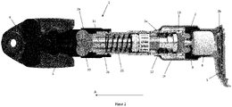
- a machine tool 1 according to the invention is shown in an exemplary embodiment as a pipe press.
- the machine tool 1 can also be configured as any other cutting or forming tool.
- the machine tool 1 according to the invention it is also possible for the machine tool 1 according to the invention to be designed as a dispensing device for chemical substances, such as adhesive or dowel compound. Such squeezing devices can also be referred to as dispensers.
- the machine tool 1 designed as a pipe press essentially has a housing 2 , a tool holder 3 and an energy supply 4 .
- the housing 2 of the machine tool 1 is essentially cylindrical and contains a front end 2a, a rear end 2b, a left side surface 2c, a right side surface 2d, a top 2e and a bottom 2f.
- a central portion 2g of the housing 2 serves as a handle for holding or guiding the machine tool 1. In den Figures 1 to 3 only the left side face 2c is shown.
- the housing 2 transitions into a preferably metallic housing section 52 .
- the power supply 4 is positioned at the rear end 2b of the housing 2 of the machine tool 1 .
- the energy supply 4 is designed as an accumulator (also referred to as an accumulator or battery), preferably as a lithium-based accumulator.
- the energy supply 4 designed as an accumulator can be releasably connected to the rear end 2b of the housing 2 of the machine tool 1 via an interface 5 .
- the machine tool 1 or the electrical consumers of the machine tool 1 are supplied with electrical energy with the aid of the accumulator 4 .
- the power supply 4 of the machine tool 1 can also be designed as a power cable for connecting the machine tool 1 to a mains power source (i.e. socket).
- the tool holder 3 is positioned on the front end 2a of the housing 2 of the machine tool 1 for releasably receiving and holding a tool 6.
- a tool 6 in the form of a forming tool is positioned on the tool holder 3.
- the forming tool 6 is designed as a so-called press head.
- the forming tool 6 designed as a pressing head is essentially used for processing and in particular for forming lines, i.e. pipes and tubes. The lines are not shown in the figures.
- An activation switch 7 is positioned on the underside 2f of the housing 2 of the machine tool 1 .
- the machine tool 1 can be started and stopped with the aid of the activation switch 7 .
- a drive 8 Inside the housing 2 of the machine tool 1, a drive 8, a drive shaft 9, an eccentric gear device 10, an output shaft 11, a threaded spindle drive 12 and a linear actuator 13 are essentially positioned.
- the drive 8 is designed as a brushless electric motor.
- the drive 8 designed as a brushless electric motor is connected to the eccentric gear device 10 via the drive shaft 9 .
- a torque generated in the drive 8 is transmitted from the drive 8 to the eccentric gear device 10 through the connection to the drive shaft 9 .
- the output shaft 11 borders on the threaded spindle drive 12 .
- the threaded spindle drive 12 is connected to the output shaft 11 .
- the rotational movement of the output shaft 11 can be converted into a linear movement by the threaded spindle drive 12 .
- the output shaft 11 is designed as a telescoping shaft device. It is therefore variable in length. For this purpose, it has a provided with one or more longitudinal grooves Groove element 54 on which a fitting piece 56 is guided in an axially displaceable manner.
- one of the longitudinal grooves 58 can be seen as an example.
- the grooved element 54 is driven in rotation by the eccentric gear device 10, as a result of which the fitting piece 56 guided in the grooved element 54 is entrained and thus driven.
- the fitting piece 56 is in turn connected to a part of the threaded spindle drive 12 in a rotationally fixed manner via an axially arranged shaft section 60 , in particular via a splined shaft connection.
- the threaded spindle drive 12 is connected to the linear actuator 13, in particular by means of an inner threaded spindle part 42, which is to be explained in more detail, and a ball bearing 62.
- the linear actuator 13 is rotationally decoupled from the threaded spindle drive 12 and thus also from the output shaft 11 by the ball bearing 62, so that it can perform purely translatory movements.
- the linear actuator 13 essentially contains a compression spring 25 and a push rod 26.
- the compression spring 25 acts as a return spring for the linear actuator 13.
- a force flow deflection device 27 is provided on the linear actuator 13 . With the help of the linear actuator 13 and the power flow deflection device 27, the linear force of the linear actuator 13 is transmitted to the tool holder 3 in such a way that the tool 6, which is designed as a compression head, can be moved between an open and closed position.
- the drive 8 designed as an electric motor can be set up to rotate at a maximum extension and retraction speed of the linear actuator 13 at a speed value between 10,000 and 30,000 rpm. In particular, a speed value between 15,000 and 25,000 rpm is provided for the drive 8 .
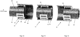
- Figures 4 to 6 show partially sectioned, perspective views of the threaded spindle drive 12 in different states.
- the threaded spindle drive 12 has an outer threaded spindle part 40 in which the inner threaded spindle part 42 can be displaced by means of bearing rollers 44, one of which is shown in FIG figure 4 is provided with a reference number, is stored.
- the two threaded spindle parts 40, 42 are cylindrical or at least essentially cylindrical.
- the outer lead screw part 40 and the inner lead screw part 42 are formed from a metal.
- the inner threaded spindle part 42 can be moved along an axial direction A of the threaded spindle drive 12, in particular along its longitudinal direction.
- the outer threaded spindle part 40 has an internal thread 48 and the inner threaded spindle part 42 has an external thread 50 .
- the internal thread 48 and the external thread 50 are only in figure 4 marked with a reference number.
- the threads 48, 50 are matched to one another. In particular, their gradients correspond.
- the threads 48, 50 can preferably have pitch angles in the range from 0.4 to 4°, for example 2°.
- the bearing rollers 44 are in the form of rods, in particular in the form of solid cylinders. Their diameters preferably correspond essentially to half the difference between the diameters of the two threaded spindle parts 40, 42 4 a groove 53 is marked as an example. The grooves 53 run parallel to one another. Their distance from one another is matched to the threads 48, 50.
- the bearing rollers 44 are arranged in a cage 46 .
- the cage 46 is made of a plastic, alternatively it can also be made of a metal.
- the outer threaded spindle part 40 is attached to the housing section 52 (see figure 3 ) non-rotatable and non-displaceable. The outer threaded spindle part 40 is thus stationary relative to the rest of the machine tool 1 (see also figure 3 ).
- a rotation of the inner threaded spindle part 42 relative to the outer threaded spindle part 40 leads to a translation of the inner threaded spindle part 42 along the axial direction A relative to the outer threaded spindle part 40, which is stationary relative to the rest of the machine tool 1.
- the cage 46 also moves together with the bearing rollers 44 within the outer threaded spindle part 40 with.
- the inner threaded spindle part 42 is displaced along the axial direction A at twice the speed as the cage 46 or the bearing rollers 44.
- the amplitude range of the displacement movement of the inner threaded spindle part 42 is twice as large as that of the cage 46 or the bearing rollers 44.
- the outer threaded spindle part 40 is twice as long as the cage 46.
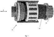
- figure 7 shows the threaded spindle drive 12 in a perspective, partially sectioned view. It can be seen in particular that the inner threaded spindle part 42 at one end, in particular at that of the output shaft 11 ( figure 3 ) end facing, a splined shaft portion 64 for connection to the shaft portion 60 ( figure 3 ) having.
- the threaded spindle drive 12, in particular in connection with the drive 8, can be set up to exert a maximum shearing pressure in the range from 7 N/mm 2 to 14 N/mm 2 , preferably 14 N/mm 2 , on the linear actuator 13 .
- it can be set up to drive the linear actuator at a maximum peripheral speed in the range from 5 m/s to 100 m/s, in particular 60 m/s.
Landscapes
- Engineering & Computer Science (AREA)
- Mechanical Engineering (AREA)
- Retarders (AREA)
- Transmission Devices (AREA)
Priority Applications (4)
| Application Number | Priority Date | Filing Date | Title |
|---|---|---|---|
| US18/035,413 US12257676B2 (en) | 2020-11-27 | 2021-09-13 | Power tool with threaded spindle drive |
| CN202180073617.4A CN116507434A (zh) | 2020-11-27 | 2021-09-13 | 具有螺纹主轴驱动器的动力工具 |
| PCT/EP2021/075036 WO2022111875A1 (fr) | 2020-11-27 | 2021-09-13 | Machine-outil ayant un engrenage à vis |
| EP21778362.0A EP4251370A1 (fr) | 2020-11-27 | 2021-09-13 | Machine-outil ayant un engrenage à vis |
Applications Claiming Priority (1)
| Application Number | Priority Date | Filing Date | Title |
|---|---|---|---|
| EP20210196.0A EP4005733A1 (fr) | 2020-11-27 | 2020-11-27 | Engrenage excentrique pour une machine-outil |
Publications (3)
| Publication Number | Publication Date |
|---|---|
| EP4005735A1 true EP4005735A1 (fr) | 2022-06-01 |
| EP4005735B1 EP4005735B1 (fr) | 2024-04-10 |
| EP4005735C0 EP4005735C0 (fr) | 2024-04-10 |
Family
ID=73642594
Family Applications (4)
| Application Number | Title | Priority Date | Filing Date |
|---|---|---|---|
| EP20210196.0A Withdrawn EP4005733A1 (fr) | 2020-11-27 | 2020-11-27 | Engrenage excentrique pour une machine-outil |
| EP21156580.9A Active EP4005735B1 (fr) | 2020-11-27 | 2021-02-11 | Machine-outil pourvu d'arbre de sortie à vis |
| EP21778362.0A Pending EP4251370A1 (fr) | 2020-11-27 | 2021-09-13 | Machine-outil ayant un engrenage à vis |
| EP21810008.9A Active EP4251371B1 (fr) | 2020-11-27 | 2021-11-10 | Engrenage excentrique pour une machine-outil |
Family Applications Before (1)
| Application Number | Title | Priority Date | Filing Date |
|---|---|---|---|
| EP20210196.0A Withdrawn EP4005733A1 (fr) | 2020-11-27 | 2020-11-27 | Engrenage excentrique pour une machine-outil |
Family Applications After (2)
| Application Number | Title | Priority Date | Filing Date |
|---|---|---|---|
| EP21778362.0A Pending EP4251370A1 (fr) | 2020-11-27 | 2021-09-13 | Machine-outil ayant un engrenage à vis |
| EP21810008.9A Active EP4251371B1 (fr) | 2020-11-27 | 2021-11-10 | Engrenage excentrique pour une machine-outil |
Country Status (4)
| Country | Link |
|---|---|
| US (2) | US12257676B2 (fr) |
| EP (4) | EP4005733A1 (fr) |
| CN (2) | CN116507434A (fr) |
| WO (2) | WO2022111875A1 (fr) |
Families Citing this family (5)
| Publication number | Priority date | Publication date | Assignee | Title |
|---|---|---|---|---|
| EP4005733A1 (fr) | 2020-11-27 | 2022-06-01 | Hilti Aktiengesellschaft | Engrenage excentrique pour une machine-outil |
| EP4006382A1 (fr) | 2020-11-30 | 2022-06-01 | Hilti Aktiengesellschaft | Élément ressort sur le dispositif d'accouplement |
| USD1042068S1 (en) * | 2021-05-19 | 2024-09-17 | Gustav Klauke Gmbh | Hydraulic press tool |
| DE102022212148A1 (de) * | 2022-11-15 | 2024-05-16 | Mahle International Gmbh | Crimp-Werkzeug und damit hergestellter Wärmeübertrager |
| EP4530021A1 (fr) * | 2023-09-28 | 2025-04-02 | Hilti Aktiengesellschaft | Machine-outil mobile avec une vis sans fin à butée |
Citations (3)
| Publication number | Priority date | Publication date | Assignee | Title |
|---|---|---|---|---|
| DE102018209819A1 (de) * | 2018-06-18 | 2019-12-19 | Zf Friedrichshafen Ag | Spindelantrieb für eine steer-by-wire-Lenkung sowie steer-by-wire-Lenkung |
| DE102018115788A1 (de) * | 2018-06-29 | 2020-01-02 | Schaeffler Technologies AG & Co. KG | Gewindetrieb und Linearaktuator mit diesem Gewindetrieb |
| DE102018124646A1 (de) * | 2018-10-05 | 2020-04-09 | Rothenberger Ag | Handwerkzeug zum umformenden und/oder trennenden Bearbeiten von Kunststoff- oder Metallwerkstücken, insbesondere Kunststoff- oder Metallrohren |
Family Cites Families (29)
| Publication number | Priority date | Publication date | Assignee | Title |
|---|---|---|---|---|
| US4799844A (en) * | 1988-01-11 | 1989-01-24 | Trw Inc | Elliptical thread design |
| US5195354A (en) * | 1989-03-31 | 1993-03-23 | Japan Storage Battery Co., Ltd. | Cam crank mechanism and motor driven hydraulic tool |
| US5511439A (en) | 1994-07-22 | 1996-04-30 | Las Navas Garcia; Jose M. | Pushing mechansim |
| NL1011731C2 (nl) | 1999-04-06 | 2000-10-09 | Skf Engineering & Res Services | Actuator met compacte tandwielreductie. |
| EP1055488B1 (fr) | 1999-05-28 | 2007-08-08 | REMS-WERK Christian Föll und Söhne GmbH & Co | Dispositif pour l'application d'une force de pressage |
| DE10064901A1 (de) * | 2000-03-27 | 2001-10-04 | Continental Teves Ag & Co Ohg | Betätigungseinheit mit einem Gewindetrieb, einem Planetengetriebe und einem von diesen beeinflußten Betätigungselement |
| CN100404935C (zh) * | 2002-06-20 | 2008-07-23 | 株式会社开滋 | 用于阀门的致动器 |
| US20050103170A1 (en) | 2003-11-18 | 2005-05-19 | Norberto Del Rio | Hydroligripcut pliers |
| DE102006023535B4 (de) | 2006-05-19 | 2008-12-18 | Keiper Gmbh & Co.Kg | Getriebestufe für einen Stellantrieb |
| DE102009040460B4 (de) | 2009-09-01 | 2023-01-12 | Adient Us Llc | Antriebseinheit für einen Fahrzeugsitz, System und Fahrzeugsitz |
| DE202009015515U1 (de) * | 2009-11-17 | 2011-04-07 | Novopress Gmbh Pressen Und Presswerkzeuge & Co. Kommanditgesellschaft | Handgeführtes Pressgerät |
| DE202011101675U1 (de) | 2011-06-10 | 2012-09-13 | Novopress Gmbh Pressen Und Presswerkzeuge & Co. Kg | Elektrohydraulisches Pressgerät |
| FR3009902B1 (fr) * | 2013-08-20 | 2015-09-04 | Virax Sa | Dispositif de detection de presence d'un outil amovible d'un actionneur lineaire |
| FR3009905B1 (fr) * | 2013-08-20 | 2015-09-04 | Virax Sa | Dispositif de detection de butee arriere sur un actionneur lineaire |
| FR3010254B1 (fr) | 2013-08-27 | 2017-02-10 | Virax Sa | Actionneur lineaire a architecture en ligne |
| US9808851B2 (en) * | 2015-04-02 | 2017-11-07 | Milwaukee Electric Tool Corporation | PEX crimping tool |
| ITUA20161807A1 (it) * | 2016-03-18 | 2017-09-18 | Cembre Spa | Utensile oleodinamico di compressione o taglio |
| US10512964B2 (en) * | 2016-12-14 | 2019-12-24 | Ridge Tool Company | Electrically powered crimp tool |
| US10675805B2 (en) * | 2016-12-14 | 2020-06-09 | Ridge Tool Company | Electrically powered crimp tool and method of using |
| DE102018121971A1 (de) | 2018-09-10 | 2020-03-12 | Gustav Klauke Gmbh | Presswerkzeug |
| WO2020069696A1 (fr) * | 2018-10-05 | 2020-04-09 | Rothenberger Ag | Outil à main destiné à l'usinage par formage et/ou par découpage de pièces en plastique ou en métal, en particulier de tubes en plastique ou en métal |
| EP3639941B1 (fr) * | 2018-10-19 | 2026-03-18 | Emerson Professional Tools AG | Machine à presser pourvu de système capteur destiné à l'identification de pièces à usiner |
| RU2018139004A (ru) * | 2018-11-06 | 2020-05-12 | Акционерное общество "Диаконт" | Линейный электромеханический привод c возможностью смазывания без демонтажа |
| EP3653341A1 (fr) | 2018-11-13 | 2020-05-20 | Hilti Aktiengesellschaft | Machine-outil portative |
| KR102130846B1 (ko) | 2019-04-26 | 2020-07-03 | 주식회사평화발레오 | 회전 출력형 액추에이터 |
| US11236849B2 (en) * | 2019-09-04 | 2022-02-01 | Techtronic Cordless Gp | Pressing tool and method for a re-pressing operation |
| EP4005733A1 (fr) * | 2020-11-27 | 2022-06-01 | Hilti Aktiengesellschaft | Engrenage excentrique pour une machine-outil |
| EP4006382A1 (fr) | 2020-11-30 | 2022-06-01 | Hilti Aktiengesellschaft | Élément ressort sur le dispositif d'accouplement |
| EP4005734A1 (fr) | 2020-11-30 | 2022-06-01 | Hilti Aktiengesellschaft | Mécanisme d'accouplement |
-
2020
- 2020-11-27 EP EP20210196.0A patent/EP4005733A1/fr not_active Withdrawn
-
2021
- 2021-02-11 EP EP21156580.9A patent/EP4005735B1/fr active Active
- 2021-09-13 US US18/035,413 patent/US12257676B2/en active Active
- 2021-09-13 EP EP21778362.0A patent/EP4251370A1/fr active Pending
- 2021-09-13 WO PCT/EP2021/075036 patent/WO2022111875A1/fr not_active Ceased
- 2021-09-13 CN CN202180073617.4A patent/CN116507434A/zh active Pending
- 2021-11-10 WO PCT/EP2021/081220 patent/WO2022111998A1/fr not_active Ceased
- 2021-11-10 CN CN202180079187.7A patent/CN116490299A/zh active Pending
- 2021-11-10 US US18/037,255 patent/US12479073B2/en active Active
- 2021-11-10 EP EP21810008.9A patent/EP4251371B1/fr active Active
Patent Citations (3)
| Publication number | Priority date | Publication date | Assignee | Title |
|---|---|---|---|---|
| DE102018209819A1 (de) * | 2018-06-18 | 2019-12-19 | Zf Friedrichshafen Ag | Spindelantrieb für eine steer-by-wire-Lenkung sowie steer-by-wire-Lenkung |
| DE102018115788A1 (de) * | 2018-06-29 | 2020-01-02 | Schaeffler Technologies AG & Co. KG | Gewindetrieb und Linearaktuator mit diesem Gewindetrieb |
| DE102018124646A1 (de) * | 2018-10-05 | 2020-04-09 | Rothenberger Ag | Handwerkzeug zum umformenden und/oder trennenden Bearbeiten von Kunststoff- oder Metallwerkstücken, insbesondere Kunststoff- oder Metallrohren |
Non-Patent Citations (1)
| Title |
|---|
| NN: "Spielfreier Rollgewindetrieb", F & M. FEINWERKTECHNIK MIKROTECHNIK MESSTECHNIK, HANSER, MUNCHEN, DE, vol. 103, no. 5, 1 May 1995 (1995-05-01), pages 255, XP002126235, ISSN: 0944-1018 * |
Also Published As
| Publication number | Publication date |
|---|---|
| CN116507434A (zh) | 2023-07-28 |
| US12479073B2 (en) | 2025-11-25 |
| WO2022111875A1 (fr) | 2022-06-02 |
| CN116490299A (zh) | 2023-07-25 |
| EP4005733A1 (fr) | 2022-06-01 |
| EP4251371A1 (fr) | 2023-10-04 |
| EP4005735B1 (fr) | 2024-04-10 |
| US20230415218A1 (en) | 2023-12-28 |
| EP4005735C0 (fr) | 2024-04-10 |
| EP4251371B1 (fr) | 2024-09-04 |
| US12257676B2 (en) | 2025-03-25 |
| US20230405779A1 (en) | 2023-12-21 |
| WO2022111998A1 (fr) | 2022-06-02 |
| EP4251370A1 (fr) | 2023-10-04 |
Similar Documents
| Publication | Publication Date | Title |
|---|---|---|
| EP4005735B1 (fr) | Machine-outil pourvu d'arbre de sortie à vis | |
| EP4251903B1 (fr) | Élément ressort sur le dispositif d'accouplement | |
| EP4005734A1 (fr) | Mécanisme d'accouplement | |
| DE102017212823A1 (de) | Spindelantriebseinrichtung | |
| EP2138256B1 (fr) | Mécanisme d'entraînement à excentrique réglable pour une machine-outil, en particulier destiné à la superfinition ou l'empierrement | |
| DE112018008218T5 (de) | Kompressions- oder Schneidwerkzeug | |
| DE10313739A1 (de) | Kupplungsbetätigungen | |
| DE10218112B4 (de) | Fahrzeugbremse | |
| EP3641983B1 (fr) | Plateau rotatif comprenant un entraînement optimisé en force | |
| DE69422982T2 (de) | Rotationsschalter mit externen lagern | |
| EP1820600A1 (fr) | Broche de perçage pour centre de traitement horizontal ou vertical dotée d'un entraînement intérieur à puissance dérivée | |
| DE102016219220B4 (de) | Hydraulikantrieb | |
| DE102018105537A1 (de) | Pressvorrichtung mit zwei Übersetzungsverhältnissen | |
| EP0903494A1 (fr) | Pompe hydraulique | |
| EP2186606B1 (fr) | Dispositif d'adaptateur pour une presse tubulaire | |
| DE102011084489A1 (de) | Vorrichtung zum Betreiben eines Presskolbens | |
| DE2703661A1 (de) | Mechanische transmission | |
| EP1225349B1 (fr) | Procédé d'assemblage d'un joint à rotule | |
| EP4530021A1 (fr) | Machine-outil mobile avec une vis sans fin à butée | |
| DE10252046B4 (de) | Antrieb für eine Spritzgiessmaschine | |
| DE202018101354U1 (de) | Pressvorrichtung mit zwei Übersetzungsverhältnissen | |
| EP4148298A1 (fr) | Dispositif d'engrenage pour une machine-outil | |
| EP4385665A1 (fr) | Dispositif de pressage | |
| EP1559922B1 (fr) | Embrayage | |
| EP4385664A1 (fr) | Outil électrique portatif et procédé de fonctionnement d'un outil électrique portatif |
Legal Events
| Date | Code | Title | Description |
|---|---|---|---|
| PUAI | Public reference made under article 153(3) epc to a published international application that has entered the european phase |
Free format text: ORIGINAL CODE: 0009012 |
|
| STAA | Information on the status of an ep patent application or granted ep patent |
Free format text: STATUS: THE APPLICATION HAS BEEN PUBLISHED |
|
| AK | Designated contracting states |
Kind code of ref document: A1 Designated state(s): AL AT BE BG CH CY CZ DE DK EE ES FI FR GB GR HR HU IE IS IT LI LT LU LV MC MK MT NL NO PL PT RO RS SE SI SK SM TR |
|
| STAA | Information on the status of an ep patent application or granted ep patent |
Free format text: STATUS: REQUEST FOR EXAMINATION WAS MADE |
|
| 17P | Request for examination filed |
Effective date: 20221201 |
|
| RBV | Designated contracting states (corrected) |
Designated state(s): AL AT BE BG CH CY CZ DE DK EE ES FI FR GB GR HR HU IE IS IT LI LT LU LV MC MK MT NL NO PL PT RO RS SE SI SK SM TR |
|
| GRAP | Despatch of communication of intention to grant a patent |
Free format text: ORIGINAL CODE: EPIDOSNIGR1 |
|
| STAA | Information on the status of an ep patent application or granted ep patent |
Free format text: STATUS: GRANT OF PATENT IS INTENDED |
|
| RIC1 | Information provided on ipc code assigned before grant |
Ipc: H01R 43/042 20060101ALI20231219BHEP Ipc: B25B 25/00 20060101ALI20231219BHEP Ipc: B21D 39/04 20060101ALI20231219BHEP Ipc: B25B 27/10 20060101AFI20231219BHEP |
|
| INTG | Intention to grant announced |
Effective date: 20240116 |
|
| GRAS | Grant fee paid |
Free format text: ORIGINAL CODE: EPIDOSNIGR3 |
|
| GRAA | (expected) grant |
Free format text: ORIGINAL CODE: 0009210 |
|
| STAA | Information on the status of an ep patent application or granted ep patent |
Free format text: STATUS: THE PATENT HAS BEEN GRANTED |
|
| AK | Designated contracting states |
Kind code of ref document: B1 Designated state(s): AL AT BE BG CH CY CZ DE DK EE ES FI FR GB GR HR HU IE IS IT LI LT LU LV MC MK MT NL NO PL PT RO RS SE SI SK SM TR |
|
| REG | Reference to a national code |
Ref country code: GB Ref legal event code: FG4D Free format text: NOT ENGLISH |
|
| REG | Reference to a national code |
Ref country code: CH Ref legal event code: EP |
|
| REG | Reference to a national code |
Ref country code: DE Ref legal event code: R096 Ref document number: 502021003254 Country of ref document: DE |
|
| REG | Reference to a national code |
Ref country code: IE Ref legal event code: FG4D Free format text: LANGUAGE OF EP DOCUMENT: GERMAN |
|
| U01 | Request for unitary effect filed |
Effective date: 20240412 |
|
| U07 | Unitary effect registered |
Designated state(s): AT BE BG DE DK EE FI FR IT LT LU LV MT NL PT SE SI Effective date: 20240422 |
|
| PG25 | Lapsed in a contracting state [announced via postgrant information from national office to epo] |
Ref country code: IS Free format text: LAPSE BECAUSE OF FAILURE TO SUBMIT A TRANSLATION OF THE DESCRIPTION OR TO PAY THE FEE WITHIN THE PRESCRIBED TIME-LIMIT Effective date: 20240810 |
|
| PG25 | Lapsed in a contracting state [announced via postgrant information from national office to epo] |
Ref country code: HR Free format text: LAPSE BECAUSE OF FAILURE TO SUBMIT A TRANSLATION OF THE DESCRIPTION OR TO PAY THE FEE WITHIN THE PRESCRIBED TIME-LIMIT Effective date: 20240410 |
|
| PG25 | Lapsed in a contracting state [announced via postgrant information from national office to epo] |
Ref country code: GR Free format text: LAPSE BECAUSE OF FAILURE TO SUBMIT A TRANSLATION OF THE DESCRIPTION OR TO PAY THE FEE WITHIN THE PRESCRIBED TIME-LIMIT Effective date: 20240711 |
|
| PG25 | Lapsed in a contracting state [announced via postgrant information from national office to epo] |
Ref country code: ES Free format text: LAPSE BECAUSE OF FAILURE TO SUBMIT A TRANSLATION OF THE DESCRIPTION OR TO PAY THE FEE WITHIN THE PRESCRIBED TIME-LIMIT Effective date: 20240410 |
|
| PG25 | Lapsed in a contracting state [announced via postgrant information from national office to epo] |
Ref country code: PL Free format text: LAPSE BECAUSE OF FAILURE TO SUBMIT A TRANSLATION OF THE DESCRIPTION OR TO PAY THE FEE WITHIN THE PRESCRIBED TIME-LIMIT Effective date: 20240410 |
|
| PG25 | Lapsed in a contracting state [announced via postgrant information from national office to epo] |
Ref country code: PL Free format text: LAPSE BECAUSE OF FAILURE TO SUBMIT A TRANSLATION OF THE DESCRIPTION OR TO PAY THE FEE WITHIN THE PRESCRIBED TIME-LIMIT Effective date: 20240410 Ref country code: NO Free format text: LAPSE BECAUSE OF FAILURE TO SUBMIT A TRANSLATION OF THE DESCRIPTION OR TO PAY THE FEE WITHIN THE PRESCRIBED TIME-LIMIT Effective date: 20240710 Ref country code: IS Free format text: LAPSE BECAUSE OF FAILURE TO SUBMIT A TRANSLATION OF THE DESCRIPTION OR TO PAY THE FEE WITHIN THE PRESCRIBED TIME-LIMIT Effective date: 20240810 Ref country code: HR Free format text: LAPSE BECAUSE OF FAILURE TO SUBMIT A TRANSLATION OF THE DESCRIPTION OR TO PAY THE FEE WITHIN THE PRESCRIBED TIME-LIMIT Effective date: 20240410 Ref country code: GR Free format text: LAPSE BECAUSE OF FAILURE TO SUBMIT A TRANSLATION OF THE DESCRIPTION OR TO PAY THE FEE WITHIN THE PRESCRIBED TIME-LIMIT Effective date: 20240711 Ref country code: ES Free format text: LAPSE BECAUSE OF FAILURE TO SUBMIT A TRANSLATION OF THE DESCRIPTION OR TO PAY THE FEE WITHIN THE PRESCRIBED TIME-LIMIT Effective date: 20240410 Ref country code: RS Free format text: LAPSE BECAUSE OF FAILURE TO SUBMIT A TRANSLATION OF THE DESCRIPTION OR TO PAY THE FEE WITHIN THE PRESCRIBED TIME-LIMIT Effective date: 20240710 |
|
| REG | Reference to a national code |
Ref country code: DE Ref legal event code: R097 Ref document number: 502021003254 Country of ref document: DE |
|
| PG25 | Lapsed in a contracting state [announced via postgrant information from national office to epo] |
Ref country code: CZ Free format text: LAPSE BECAUSE OF FAILURE TO SUBMIT A TRANSLATION OF THE DESCRIPTION OR TO PAY THE FEE WITHIN THE PRESCRIBED TIME-LIMIT Effective date: 20240410 |
|
| PG25 | Lapsed in a contracting state [announced via postgrant information from national office to epo] |
Ref country code: RO Free format text: LAPSE BECAUSE OF FAILURE TO SUBMIT A TRANSLATION OF THE DESCRIPTION OR TO PAY THE FEE WITHIN THE PRESCRIBED TIME-LIMIT Effective date: 20240410 Ref country code: SK Free format text: LAPSE BECAUSE OF FAILURE TO SUBMIT A TRANSLATION OF THE DESCRIPTION OR TO PAY THE FEE WITHIN THE PRESCRIBED TIME-LIMIT Effective date: 20240410 |
|
| PG25 | Lapsed in a contracting state [announced via postgrant information from national office to epo] |
Ref country code: SM Free format text: LAPSE BECAUSE OF FAILURE TO SUBMIT A TRANSLATION OF THE DESCRIPTION OR TO PAY THE FEE WITHIN THE PRESCRIBED TIME-LIMIT Effective date: 20240410 |
|
| PG25 | Lapsed in a contracting state [announced via postgrant information from national office to epo] |
Ref country code: SM Free format text: LAPSE BECAUSE OF FAILURE TO SUBMIT A TRANSLATION OF THE DESCRIPTION OR TO PAY THE FEE WITHIN THE PRESCRIBED TIME-LIMIT Effective date: 20240410 Ref country code: SK Free format text: LAPSE BECAUSE OF FAILURE TO SUBMIT A TRANSLATION OF THE DESCRIPTION OR TO PAY THE FEE WITHIN THE PRESCRIBED TIME-LIMIT Effective date: 20240410 Ref country code: RO Free format text: LAPSE BECAUSE OF FAILURE TO SUBMIT A TRANSLATION OF THE DESCRIPTION OR TO PAY THE FEE WITHIN THE PRESCRIBED TIME-LIMIT Effective date: 20240410 Ref country code: CZ Free format text: LAPSE BECAUSE OF FAILURE TO SUBMIT A TRANSLATION OF THE DESCRIPTION OR TO PAY THE FEE WITHIN THE PRESCRIBED TIME-LIMIT Effective date: 20240410 |
|
| PLBE | No opposition filed within time limit |
Free format text: ORIGINAL CODE: 0009261 |
|
| STAA | Information on the status of an ep patent application or granted ep patent |
Free format text: STATUS: NO OPPOSITION FILED WITHIN TIME LIMIT |
|
| 26N | No opposition filed |
Effective date: 20250113 |
|
| U20 | Renewal fee for the european patent with unitary effect paid |
Year of fee payment: 5 Effective date: 20250221 |
|
| PG25 | Lapsed in a contracting state [announced via postgrant information from national office to epo] |
Ref country code: MC Free format text: LAPSE BECAUSE OF FAILURE TO SUBMIT A TRANSLATION OF THE DESCRIPTION OR TO PAY THE FEE WITHIN THE PRESCRIBED TIME-LIMIT Effective date: 20240410 |
|
| PG25 | Lapsed in a contracting state [announced via postgrant information from national office to epo] |
Ref country code: IE Free format text: LAPSE BECAUSE OF NON-PAYMENT OF DUE FEES Effective date: 20250211 |
|
| REG | Reference to a national code |
Ref country code: CH Ref legal event code: U11 Free format text: ST27 STATUS EVENT CODE: U-0-0-U10-U11 (AS PROVIDED BY THE NATIONAL OFFICE) Effective date: 20260301 |
|
| U20 | Renewal fee for the european patent with unitary effect paid |
Year of fee payment: 6 Effective date: 20260225 |
|
| PGFP | Annual fee paid to national office [announced via postgrant information from national office to epo] |
Ref country code: GB Payment date: 20260220 Year of fee payment: 6 |
|
| PGFP | Annual fee paid to national office [announced via postgrant information from national office to epo] |
Ref country code: CH Payment date: 20260301 Year of fee payment: 6 |