EP4005781B1 - Werkzeug - Google Patents
Werkzeug Download PDFInfo
- Publication number
- EP4005781B1 EP4005781B1 EP21209729.9A EP21209729A EP4005781B1 EP 4005781 B1 EP4005781 B1 EP 4005781B1 EP 21209729 A EP21209729 A EP 21209729A EP 4005781 B1 EP4005781 B1 EP 4005781B1
- Authority
- EP
- European Patent Office
- Prior art keywords
- panel
- inserts
- end edge
- insert
- tool according
- Prior art date
- Legal status (The legal status is an assumption and is not a legal conclusion. Google has not performed a legal analysis and makes no representation as to the accuracy of the status listed.)
- Active
Links
Images


Classifications
-
- B—PERFORMING OPERATIONS; TRANSPORTING
- B29—WORKING OF PLASTICS; WORKING OF SUBSTANCES IN A PLASTIC STATE IN GENERAL
- B29C—SHAPING OR JOINING OF PLASTICS; SHAPING OF MATERIAL IN A PLASTIC STATE, NOT OTHERWISE PROVIDED FOR; AFTER-TREATMENT OF THE SHAPED PRODUCTS, e.g. REPAIRING
- B29C70/00—Shaping composites, i.e. plastics material comprising reinforcements, fillers or preformed parts, e.g. inserts
- B29C70/04—Shaping composites, i.e. plastics material comprising reinforcements, fillers or preformed parts, e.g. inserts comprising reinforcements only, e.g. self-reinforcing plastics
- B29C70/28—Shaping operations therefor
- B29C70/40—Shaping or impregnating by compression not applied
- B29C70/42—Shaping or impregnating by compression not applied for producing articles of definite length, i.e. discrete articles
- B29C70/44—Shaping or impregnating by compression not applied for producing articles of definite length, i.e. discrete articles using isostatic pressure, e.g. pressure difference-moulding, vacuum bag-moulding, autoclave-moulding or expanding rubber-moulding
- B29C70/446—Moulding structures having an axis of symmetry or at least one channel, e.g. tubular structures, frames
-
- B—PERFORMING OPERATIONS; TRANSPORTING
- B29—WORKING OF PLASTICS; WORKING OF SUBSTANCES IN A PLASTIC STATE IN GENERAL
- B29D—PRODUCING PARTICULAR ARTICLES FROM PLASTICS OR FROM SUBSTANCES IN A PLASTIC STATE
- B29D99/00—Subject matter not provided for in other groups of this subclass
- B29D99/001—Producing wall or panel-like structures, e.g. for hulls, fuselages, or buildings
- B29D99/0014—Producing wall or panel-like structures, e.g. for hulls, fuselages, or buildings provided with ridges or ribs, e.g. joined ribs
-
- B—PERFORMING OPERATIONS; TRANSPORTING
- B29—WORKING OF PLASTICS; WORKING OF SUBSTANCES IN A PLASTIC STATE IN GENERAL
- B29C—SHAPING OR JOINING OF PLASTICS; SHAPING OF MATERIAL IN A PLASTIC STATE, NOT OTHERWISE PROVIDED FOR; AFTER-TREATMENT OF THE SHAPED PRODUCTS, e.g. REPAIRING
- B29C2793/00—Shaping techniques involving a cutting or machining operation
- B29C2793/0081—Shaping techniques involving a cutting or machining operation before shaping
-
- B—PERFORMING OPERATIONS; TRANSPORTING
- B29—WORKING OF PLASTICS; WORKING OF SUBSTANCES IN A PLASTIC STATE IN GENERAL
- B29L—INDEXING SCHEME ASSOCIATED WITH SUBCLASS B29C, RELATING TO PARTICULAR ARTICLES
- B29L2031/00—Other particular articles
- B29L2031/30—Vehicles, e.g. ships or aircraft, or body parts thereof
- B29L2031/3076—Aircrafts
- B29L2031/3082—Fuselages
-
- B—PERFORMING OPERATIONS; TRANSPORTING
- B29—WORKING OF PLASTICS; WORKING OF SUBSTANCES IN A PLASTIC STATE IN GENERAL
- B29L—INDEXING SCHEME ASSOCIATED WITH SUBCLASS B29C, RELATING TO PARTICULAR ARTICLES
- B29L2031/00—Other particular articles
- B29L2031/30—Vehicles, e.g. ships or aircraft, or body parts thereof
- B29L2031/3076—Aircrafts
- B29L2031/3085—Wings
-
- Y—GENERAL TAGGING OF NEW TECHNOLOGICAL DEVELOPMENTS; GENERAL TAGGING OF CROSS-SECTIONAL TECHNOLOGIES SPANNING OVER SEVERAL SECTIONS OF THE IPC; TECHNICAL SUBJECTS COVERED BY FORMER USPC CROSS-REFERENCE ART COLLECTIONS [XRACs] AND DIGESTS
- Y02—TECHNOLOGIES OR APPLICATIONS FOR MITIGATION OR ADAPTATION AGAINST CLIMATE CHANGE
- Y02T—CLIMATE CHANGE MITIGATION TECHNOLOGIES RELATED TO TRANSPORTATION
- Y02T50/00—Aeronautics or air transport
- Y02T50/40—Weight reduction
Definitions
- the present application relates to tooling for consolidating or polymerizing a stiffened panel comprising reinforcements with beveled ends.
- a stiffened panel comprises a panel, in the form of a plate, as well as reinforcements, attached to one face of the panel, extending in at least one direction in a plane substantially perpendicular to the panel.
- the reinforcements are obtained from fiber preforms 10 each having a U-shaped cross section, with a base 12 and two wings 14, 16, substantially constant in a longitudinal direction.
- each end of the wings 14, 16 has an end edge 18 substantially perpendicular to the longitudinal direction.
- each fiber preform 10 is positioned on a first tool 20 then the different first tools 20 are arranged on a support 22, the bases 12 of the different fiber preforms 10 being oriented upwards, the wings 14, 16 two adjacent fiber preforms 10 being pressed against each other.
- profiles 24 with a nail head section are positioned at the level of the junction planes of the fiber preforms 10, then fiber plies 26 are attached to the bases 12 of the fiber preforms 10.
- the fibers of the preforms 10 and plies 26 may be dry or pre-impregnated.
- the fiber preforms 10 and the fiber plies 26 are consolidated simultaneously or co-cooked, with an addition of resin if the fibers of the preforms 10 and the plies 26 are dry.
- a stiffened panel is obtained, the fiber plies 26 and the bases 12 of the fiber preforms 10 embedded in a resin matrix forming the panel of the stiffened panel, the wings 14, 16 fiber preforms 10 forming the reinforcements of the stiffened panel. This operating mode makes it possible to obtain continuity of the fibers between the reinforcements and the panel, which gives the stiffened panel high mechanical characteristics.
- the latter are machined from in order to obtain a beveled shape called SRO (for Stringer Run-Out in English), then a coating is applied to the machined areas in order to protect them.
- SRO Stringer Run-Out in English
- US2014352877A1 discloses a tool according to the preamble of claim 1.
- the subject of the invention is a tool for consolidating or polymerizing a stiffened panel comprising a panel as well as reinforcements attached to an internal face of the panel and parallel to each other, at least one of the reinforcements comprising at least one beveled end edge, the stiffened panel being obtained from fiber preforms each having at least one base and at least one wing comprising end edges, the end edges of the wings of the fiber preforms corresponding to the beveled end edge of the reinforcement being beveled before a step of consolidation or polymerization of the stiffened panel.
- the tooling comprises a first mold for each fiber preform, an insert for each beveled end edge of the reinforcements against which are pressed in operation beveled end edges of the wings of two fiber preforms plated l one against the other to form the reinforcement as well as at least one holding and positioning element connecting the inserts together.
- This tooling makes it possible to obtain a stiffened panel which comprises at least one reinforcement with at least one beveled end edge without it being necessary to machine the latter after a consolidation or polymerization step, said stiffened panel having characteristics mechanical as high as those provided by the first embodiment of the prior art.
- the tooling comprises a frame connecting the inserts together and delimiting a contour of the panel of the stiffened panel.
- the tooling comprises a counterplate connecting the inserts together, said counterplate being configured to be pressed, during the consolidation or polymerization step, against at least one ply or attached fiber preform. on the bases of the fiber preforms and forming the panel of the stiffened panel.
- the tooling comprises at least one sealing system between the inserts and the first molds.
- each insert comprises a contact surface configured to be in contact with one of the end edges of a wing of a fiber preform as well as with the inclined side located in the extension of the end edge .
- the sealing system comprises an elastic coating, with a low coefficient of expansion, covering each contact surface, which extends on either side of the insert so as to be compressed between the first molds positioned on either side of the insert.
- the insert is made entirely of an elastic material with a low coefficient of expansion.
- the tooling comprises a support on which the inserts as well as the first molds are positioned.
- the support comprises a laying surface which has a curvature identical to that of the stiffened panel to be produced.
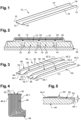
- a stiffened panel 30 comprises a panel 32 having first and second faces 32.1, 32.2 as well as reinforcements 34 positioned on the first face 32.1 of the panel 32, perpendicular to the latter.
- the reinforcements 34 are oriented in a single direction and are parallel to each other. For the remainder of the description, the reinforcements 34 are oriented in a longitudinal direction.
- the panel 32 comprises first and second edges 36.1, 36.2 oriented in a direction intersecting the longitudinal direction.
- the panel 32 has a thickness (distance between the first and second faces 32.1, 32.2) substantially constant and significantly less than the other dimensions of the panel 32.
- the first and second faces 32.1, 32.2 are flat. Alternatively, they could be curved.
- the first and second edges 36.1, 36.2 are substantially perpendicular to the longitudinal direction.
- Each reinforcement 34 has first and second faces 34.1, 34.2, a first edge 38 distant from the first face 32.1 of the panel 32, substantially parallel to the latter, as well as first and second end edges 40.1, 40.2. At least a first or second end edge 40.1, 40.2 of at least one reinforcement 34 is beveled. Thus, it is not perpendicular to the longitudinal direction but inclined. According to one configuration, the end edges 40.1, 40.2 of all the reinforcements 34 are beveled. As an indication, the first and second end edges 40.1, 40.2 have a slope p, corresponding to the angle formed between the end edges 40.1, 40.2 and the first face 32.1 of the panel 32, less than 60°.
- At least one of the first and second end edges 40.1, 40.2 is distant from the first and second edges 36.1, 36.2 of the panel 32.
- the edge of end 40.1 or 40.2 is separated from the edge 36.1 or 36.2 of the panel 32 by a distance D40.1 or D40.2.
- Each reinforcement 34 has a given profile corresponding to the geometries of the first edge 38 as well as the first and second end edges 40.1, 40.2.
- the reinforcements 34 and their first edges 38 are substantially rectilinear.
- the reinforcements 34 and/or the first edges 38 could be curved.
- a central wing box of an aircraft may comprise at least one such stiffened panel.
- a method of manufacturing a stiffened panel comprises a step of obtaining fiber preforms 42 with a U-shaped cross section comprising a base 44 and first and second wings 46, 48 oriented in the longitudinal direction .
- the manufacturing process may include a step of obtaining fiber preforms with an L-shaped cross section comprising a base and a single wing.
- the fibers of these fiber preforms 42 can be dry or pre-impregnated.
- Each fiber preform 42 has first and second ends 42.1, 42.2 separated from each other by a distance D1 substantially equal to the distance separating the first and second edges 36.1, 36.2 of the panel 32.
- Each wing 46, 48 of a fiber preform 42 has a first edge 50 distant from the base 44 as well as first and second end edges 52.1, 52.2.
- each wing 46, 48 has a profile corresponding to the geometries of the first edge 50 as well as the first and second end edges 52.1, 52.2 of the wing 46, 48.
- the first and second wings 46, 48 of two fiber preforms 42 pressed against each other form a reinforcement 34.
- Each wing 46, 48 comprises an internal face 46.1, 48.1 oriented towards the other wing of the fiber preform 42 as well as an external face 46.2, 48.2 opposite the internal face 46.1, 48.1.
- the base 44 comprises lateral edges 44.1, 44.2 in the extension of the first and second wings 46, 48 as well as an internal face 44.3 oriented towards the first and second wings 46, 48.
- each fiber preform 42 in U or L can be produced in the same manner as those described in the document FR2942165 .
- each fiber preform 42 is obtained by draping plies of fibers over a mold of rectangular cross section.
- Other solutions could be considered for the manufacture of fiber preforms 42.
- the invention is not limited to U or L-shaped sections.
- the fiber preforms 42 could have C-shaped, H, T-shaped or J-shaped.
- the fiber preform 42 comprises at least one base and at least one wing, namely two non-coplanar sections.
- At least one first or second wing 46, 48 Prior to a consolidation or polymerization step, for at least one U- or L-shaped fiber preform 42, at least one first or second wing 46, 48 has a profile identical to that of a reinforcement 34 and comprises at least one end edge 52.1, 52.2 beveled. According to the configuration visible on the figure 13 , all the first and second wings 46, 48 have first and second beveled end edges 52.1, 52.2. According to a first embodiment, the step of obtaining U- or L-shaped fiber preforms 42 is configured to obtain first and second wings 46, 48 with first and second end edges 52.1, 52.2 perpendicular to the longitudinal direction or at the base 44.
- the method of manufacturing the stiffened panel comprises a step of removing material so that at least one of the first and second end edges 52.1, 52.2 is beveled.
- the removal step is carried out by machining, using an ultrasonic knife or any other means.
- the first and second wings 46, 48 of the fiber preforms 42 are, if necessary, machined so that their profiles are substantially identical to those of the reinforcements 34 to be produced and have beveled end edges. Machining a dry fiber preform generates waste which can be more easily recycled than that resulting from the machining of an already consolidated or polymerized composite material part.
- each end edge 52.1, 52.2 of each wing 46, 48 has a slope identical to that of the end edge 40.1, 40.2 of the corresponding reinforcement 34 and it is separated from the end 42.1, 42.2 of the fiber preform 42 by a distance equal to that separating the end edge 40.1, 40.2 of the reinforcement 34 and the edge 36.1 or 36.2 of the panel 32 of the panel stiffened 30 to achieve.
- the base 44 of the fiber preform 42 has an inclined side 54 in the extension of the wing 46, 48, extending between said wing 46, 48 and the end 42.1, 42.2 of the fiber preform 42, having a width substantially equal to the thickness of the wing 46, 48
- the inclination of the inclined panel 54 is such that the base 44 has a thickness which decreases as it approaches the lateral edge 44.1 of the base 44.
- the two juxtaposed inclined sections 54 form a hollow 56 on either side of the junction plane PJ of the two fiber preforms 42.
- This hollow 56 makes it possible to be certain that the stiffened panel obtained from the two fiber preforms 42 will not present a projecting shape to the right of the junction plane PJ of the two fiber preforms 42.
- the inclined panel 54 and the base 44 form an angle ⁇ of the order of a few degrees, preferably less than 10° .
- the material removal step is configured to produce the beveled end edge 52.1, 52.2 as well as an inclined side 54 in the extension of the end edge 52.1, 52.2 and the end 42.1, 42.2 of the nearest fiber preform 42.
- the beveled end edge 52.1, 52.2 of a wing 46, 48 of a fiber preform 42 and the inclined section 54 located in its extension are connected by a curved junction zone 58 corresponding to a portion of cylinder having an axis parallel to the base 44.
- the end edges 52.1, 52.2 and the inclined sides 54 are not not connected by a sharp edge likely to form the beginning of a break.
- the junction zone 58 is not limited to this curved shape and other shapes can be considered.
- the machining step is adapted to obtain the desired slope p for each end edge 52.1, 52.2 of each wing 46 , 48 and the desired inclination for each inclined section 54 positioned in the extension of each wing 46, 48.
- the step of obtaining the U- or L-shaped fiber preform 42 is configured so that the end edges 52.1, 52.2 of the wings are obtained directly beveled.
- the fiber preform 42 is obtained by draping plies of fibers which have a suitable geometry and/or which are arranged together in a suitable manner to obtain first and second wings 46, 48 with end edges. 52.1, 52.2 beveled identical to those of the reinforcements 34 to be produced.
- the end edges 52.1, 52.2 of the wings 46, 48 of the fiber preforms 42 corresponding to the end edge 40.1, 40.2 of the reinforcement 34 are beveled before a step of consolidation or polymerization of the stiffened panel 30 so that the wings 46, 48 of the fiber preforms 42 have a profile identical to that of the reinforcement 34 before the step of consolidation or polymerization of the stiffened panel 30.
- all the first and second wings 46, 48 of all the U- or L-shaped fiber preforms 42 present, before a step of consolidation or polymerization of the fiber preforms 42, profiles identical to those of the reinforcements 34 to realize, all their end edges 52.1, 52.2 being beveled.
- the method of manufacturing the stiffened panel comprises at least one step of applying at least one coating 62, 62' to at least one material removal zone 60 obtained during the material removal step. matter.
- a protective covering 62, 62' such as a layer of glass fibers for example.
- the protective coating 62, 62' extends beyond the material removal zone 60.
- the protective coating 62 applied to a end edge 52.1 or 52.2 of a wing 46, 48 extends on either side of the end edge 52.1 or 52.2 and slightly covers the faces internal and external 46.1, 46.2, 48.1, 48.2 of the wing 46, 48, as illustrated on the figures 4 And 6 .
- the protective covering 62' applied to an inclined panel 54 extends on either side of the inclined panel 54 and covers the lateral edge 44.1, 44.2 of the base 44 and its internal face 44.3, as illustrated in the figures 5 And 7 .
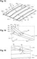
- the manufacturing process of the invention comprises a step of arranging the fiber preforms 42 relative to each other so as to form a face of the panel 32 and the reinforcements 34, a step of depositing at least one ply or preform of fibers 64 (visible on the figures 10 And 15 ) on the bases 44 of the fiber preforms 42 to form the panel 32 of the stiffened panel 30, then a step of consolidation or polymerization of the stiffened panel 30.
- a protection step whatever the operating mode for carrying it out, it is carried out prior to the step of consolidation or polymerization of the stiffened panel.
- Profiles in the shape of nail heads can be positioned at the level of the junction planes of the fiber preforms 42 before depositing the fiber plies 64.
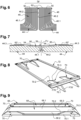
- consolidation or polymerization tools 66 as illustrated on the figures 8 to 12 , 16 and 17 , can be used.
- the tooling 66 comprises a first mold 68 for each fiber preform 42, the first mold 68 having a rectangular cross section, a first face 68.1 in contact with the base 44 of the fiber preform 42 as well as second and third faces 68.2, 68.3 in contact with the wings 46, 48 of the preform of fibers 42 parallel to each other and perpendicular to the first face 68.1 of the mold.
- the same molds can be used to manufacture the fiber preforms 42 and to arrange them relative to each other.
- the tooling 66 also includes an insert 70 for each beveled end edge 40.1, 40.2 of the reinforcements 34 against which the beveled end edges 52.1, 52.2 of the first and second wings 46, 48 of two preforms of plated fibers 42 are pressed against each other to form the reinforcement 34 during the consolidation or polymerization step. As illustrated on the figure 8 , the tooling 66 also includes a frame 72 connecting all the inserts 70 so as to keep them stationary relative to each other according to a given arrangement.
- the frame 72 is configured so as to delimit the contour of the panel 32 of the stiffened panel 30.
- the frame 72 also makes it possible to guarantee a precise distance between two inserts 70 in contact with the beveled end edges 40.1, 40.2 of the reinforcements 34 during the expansion of the mold during the polymerization of the stiffened panel 30.
- Each insert 70 comprises a base 70.1 intended to rest on the support 74.
- the contact surface 78 comprises a first part 70.2 forming an acute angle with the base 70.1 substantially equal to the angle formed between a beveled end edge 40.1, 40.2 and the panel 32 as well as a second part 70.3 substantially parallel to the base 70.1 which comprises two inclined sides, one for each inclined side 54 of the preform 42
- the insert 70 comprises two opposite faces F70, F70' configured to be pressed against the first molds 68 positioned on either side of the insert 70.
- the tooling 66 also includes a support 74 (visible on there Figure 10 ) on which the inserts 70 connected by the frame 72 as well as the first molds 68 are positioned.
- the support 74 comprises a laying surface 74.1 which has a curvature identical to that of the stiffened panel to be produced.
- the installation surface 74.1 could be flat if the first and second faces 32.1, 32.2 of the panel 32 were flat.
- each insert 70 comprises a contact surface 78 configured to be in contact with one of the end edges 52.1, 52.2 of a wing 46, 48 of a fiber preform 42 as well as with the inclined section 54 located in the extension of the end edge.
- the sealing system 76 comprises an elastic coating, with a low coefficient of expansion, covering each contact surface 78, which extends on either side of the insert 70 so as to be compressed between the first molds 68 positioned on either side of the insert 70.
- the insert 70 can be made entirely of this elastic material with a low coefficient of expansion. This solution makes it possible to guarantee a perfect seal between the insert 70 and the first molds 68 during polymerization.
- the fibers of the preforms 42 and the plies 64 may be dry.
- the tooling 66 includes at least one supply of resin.
- the frame 72 and the inserts 70 are positioned on the support 74, then the first molds 68 each with a fiber preform 42 are positioned on the support 74 between the inserts 70.
- the fiber preform 64 forming the panel 32 is attached to the bases 44 of the fiber preforms 42.
- the fiber preforms 42, 44 are consolidated or polymerized.
- each fiber preform 42 is positioned on a first mold 68 and each beveled end edge 52.1, 52.2 of the wings 46, 48, of the preforms of fibers 42 are pressed against an insert 70 positioned between two first molds 68.
- the tooling and the method of manufacturing a stiffened panel according to the invention makes it possible to obtain mechanical characteristics as high as those provided by the first embodiment of the prior art.
- the tooling 66 comprises a support 74, a set 80 of first molds, one for each fiber preform 42, inserts 70 positioned between the first molds, at least one sealing system between the inserts 70 and the first molds as well that a covering 82 connected to the support 74 by sealing elements 84.
- the tooling 66 comprises at least one counterplate 86 configured to be pressed, during the consolidation or polymerization step, against at least one ply or fiber preform 64 attached to the bases 44 of the fiber preforms 42 and forming the panel 32 of the stiffened panel.
- each insert 70 is connected to the counterplate 86 by a sliding connection so as to be movable relative to the counterplate 86 in a direction parallel to the faces F70, F70' of the inserts 70.
- the two inserts 70 are movable between a spaced position in which the inserts 70 can be placed on the support 74 and a tightened position in which the inserts 70 are pressed against the end edges 52.1, 52.2 of the wings 46, 48 of the fiber preforms 42.
- the inserts 70 are connected to this counterplate 86 which ensures that the inserts 70 are held immobile between them and guarantees precise positioning of the latter.
- the first molds 68 are positioned on the support 74 then the fiber preform 64 forming the panel 32 is attached to the bases 44 of the fiber preforms 42.
- the counterplate 86 and the inserts 70 in the spaced position are put in place, the counterplate 86 being placed against the fiber preform 64.
- the inserts 70 are translated into a tightened position. After the installation of a covering, the fiber preforms 42, 44 are consolidated or polymerized.
- the tooling 60 comprises at least one element for holding and positioning the inserts 70, such as a frame 72 or a counterplate 80 for example.
Landscapes
- Engineering & Computer Science (AREA)
- Mechanical Engineering (AREA)
- Architecture (AREA)
- Civil Engineering (AREA)
- Structural Engineering (AREA)
- Chemical & Material Sciences (AREA)
- Composite Materials (AREA)
- Moulding By Coating Moulds (AREA)
Claims (10)
- Werkzeug zur Verfestigung oder Polymerisation einer versteiften Platte, die eine Platte (32) sowie Verstärkungen (34) aufweist, die an einer Innenseite (32.1) der Platte (32) angebracht und zueinander parallel sind, wobei wenigstens eine der Verstärkungen (34) wenigstens eine abgeschrägte Endkante (40.1, 40.2) aufweist, wobei die versteifte Platte (30) aus Faservorformlingen (42) erhalten wird, die jeweils wenigstens eine Basis (44) und wenigstens einen Flügel (46, 48) mit Endkanten (52.1, 52.2) aufweisen, wobei die Endkanten (52.1, 52.2) der Flügel (46, 48) der Faservorformlinge (42), die den abgeschrägten Endkanten (40.1, 40.2) der Verstärkung (34) entsprechen, vor einem Schritt des Verfestigens oder der Polymerisation der versteiften Platte (30) abgeschrägt werden, wobei das Werkzeug eine erste Form (68) für jeden Faservorformling (42) und einen Einsatz (70) für jede Endkante (40.1, 40.2) der Verstärkungen (34)aufweist, gegen die bei der Anwendung abgeschrägte Endkanten (52.1, 52.2) der Flügel (46, 48) von zwei Faservorformlingen (42) gedrückt werden, die zur Bildung der Verstärkung (34) gegeneinander gedrückt werden, wobei das Werkzeug durch wenigstens ein Halte- und Positionierelement gekennzeichnet ist, das die Einsätze (70) miteinander verbindet.
- Werkzeug nach dem vorhergehenden Anspruch, dadurch gekennzeichnet, dass das Halte- und Positionierelement einen Rahmen (72) umfasst, der die Einsätze (70) miteinander verbindet und eine Kontur der Platte (32) der versteiften Platte (30) begrenzt.
- Werkzeug nach Anspruch 1, dadurch gekennzeichnet, dass das Halte- und Positionierungselement eine Gegenplatte (86) umfasst, die die Einsätze (70) miteinander verbindet, wobei die Gegenplatte (86) so eingerichtet ist, dass sie während des Verfestigungs- oder Polymerisationsschritts gegen wenigstens eine Falte oder einen Faservorformling (64) gedrückt wird, die/der an den Basen (44) der Faservorformlinge (42) angebracht ist und die Platte (32) der versteiften Platte bildet.
- Werkzeug nach dem vorhergehenden Anspruch, dadurch gekennzeichnet, dass jeder Einsatz (70) mit der Gegenplatte (86) durch eine Gleitverbindung verbunden ist, so dass für jedes Paar von Einsätzen (70), die zwischen denselben ersten Formen (68) positioniert sind, die Einsätze (70) zwischen einer gespreizten Position und einer verengten Position beweglich sind, in der die Einsätze (70) gegen die Endkanten (52.1, 52.2) der Flügel (46, 48) der Faservorformlinge (42) gedrückt werden.
- Werkzeug nach einem der vorhergehenden Ansprüche,
dadurch gekennzeichnet, dass das Werkzeug wenigstens ein Dichtungssystem (76) zwischen den Einsätzen (70) und den ersten Formen (68) umfasst. - Werkzeug nach dem vorhergehenden Anspruch, dadurch gekennzeichnet, dass jeder Einsatz (70) eine Kontaktfläche (78) umfasst, die so eingerichtet ist, dass sie mit einer der Endkanten (52.1, 52.2) eines Flügels (46, 48) eines Faservorformlings (42) sowie mit der geneigten Fläche (54) in Kontakt steht, die sich in der Verlängerung der Endkante befindet.
- Werkzeug nach dem vorhergehenden Anspruch, dadurch gekennzeichnet, dass das Dichtungssystem (76) eine elastische Beschichtung mit niedrigem Ausdehnungskoeffizienten aufweist, die jede Kontaktfläche (78) bedeckt, die sich auf beiden Seiten des Einsatzes (70) erstreckt, so dass sie zwischen den ersten Formen (68), die auf beiden Seiten des Einsatzes (70) positioniert sind, zusammengedrückt wird.
- Werkzeug nach Anspruch 6, dadurch gekennzeichnet, dass der Einsatz (70) vollständig aus einem elastischen Material mit einem niedrigen Ausdehnungskoeffizienten hergestellt ist.
- Werkzeug nach einem der vorhergehenden Ansprüche,
dadurch gekennzeichnet, dass das Werkzeug (66) einen Träger (74) umfasst, auf dem die Einsätze (70) sowie die ersten Formen (68) positioniert sind. - Werkzeug nach dem vorhergehenden Anspruch, dadurch gekennzeichnet, dass der Träger (74) eine Auflagefläche (74.1) aufweist, die eine Krümmung aufweist, die mit derjenigen der herzustellenden versteiften Platte identisch ist.
Applications Claiming Priority (1)
| Application Number | Priority Date | Filing Date | Title |
|---|---|---|---|
| FR2012352A FR3116755A1 (fr) | 2020-11-30 | 2020-11-30 | Procédé de fabrication d’un panneau raidi comprenant des renforts avec des extrémités biseautées et panneau raidi obtenu à partir dudit procédé |
Publications (2)
| Publication Number | Publication Date |
|---|---|
| EP4005781A1 EP4005781A1 (de) | 2022-06-01 |
| EP4005781B1 true EP4005781B1 (de) | 2023-11-22 |
Family
ID=74669005
Family Applications (1)
| Application Number | Title | Priority Date | Filing Date |
|---|---|---|---|
| EP21209729.9A Active EP4005781B1 (de) | 2020-11-30 | 2021-11-22 | Werkzeug |
Country Status (2)
| Country | Link |
|---|---|
| EP (1) | EP4005781B1 (de) |
| FR (1) | FR3116755A1 (de) |
Family Cites Families (5)
| Publication number | Priority date | Publication date | Assignee | Title |
|---|---|---|---|---|
| FR2942165B1 (fr) | 2009-02-16 | 2016-01-29 | Airbus France | Procede de fabrication d'un panneau raidi en materiau composite |
| GB0912015D0 (en) * | 2009-07-10 | 2009-08-19 | Airbus Operations Ltd | Stringer |
| ES2415773B1 (es) * | 2011-12-29 | 2014-09-02 | Airbus Operations S.L. | Método de fabricación de piezas de material compuesto con cambios de espesor |
| US8974886B2 (en) * | 2012-04-25 | 2015-03-10 | The Boeing Company | Disbond resistant composite stiffener runout |
| ES2626352T3 (es) * | 2013-05-30 | 2017-07-24 | Airbus Operations S.L. | Herramienta híbrida para curar piezas de material compuesto |
-
2020
- 2020-11-30 FR FR2012352A patent/FR3116755A1/fr not_active Ceased
-
2021
- 2021-11-22 EP EP21209729.9A patent/EP4005781B1/de active Active
Also Published As
| Publication number | Publication date |
|---|---|
| FR3116755A1 (fr) | 2022-06-03 |
| EP4005781A1 (de) | 2022-06-01 |
Similar Documents
| Publication | Publication Date | Title |
|---|---|---|
| EP0984853B1 (de) | Gerät für in-situ-reparatur einer verbundmaterialstruktur mit beschädigter stellen und verfahren hierzu | |
| CA2803974C (fr) | Procede de realisation d'un caisson central de voilure | |
| EP4248066A1 (de) | Verbundschaufel für eine flugzeugturbomaschine und verfahren zur herstellung davon | |
| CA2862686C (fr) | Procede de formage par estampage d'un materiau composite thermoplastique a renfort fibreux continu | |
| EP2639047B1 (de) | Herstellungsverfahren eines gebogenen Profils aus Verbundmaterial ausgehend von einer geraden Vorform aus Fasermatten | |
| EP1537982A1 (de) | Selbstverstärkte Verbundplatten aus Prepreg und Verfahren zur Positionierung von Teilen solcher Platten | |
| FR2960470A1 (fr) | Procede de fabrication d'un raidisseur en materiau composite avec une section en omega | |
| EP2639034B1 (de) | Verfahren zur Herstellung eines Verbundwerkstoffteils, und Werkzeug zur Umsetzung dieses Verfahrens | |
| WO2010092309A1 (fr) | Procede de fabrication d'un panneau raidi en materiau composite | |
| EP3140104B1 (de) | Verfahren zur erzeugung von vorformlingen durch aufbringen und formen ausgerichteter fasern | |
| EP1537981A1 (de) | Verfahren zum Auflegen von Prepregteile für eine selbstverstärkte Platte | |
| EP4005781A1 (de) | Werkzeug zur verfestigung oder polymerisierung einer versteiften platte, die verstärkungen mit abgeschrägten enden umfasst | |
| EP2625027B1 (de) | Verfahren zur herstellung von versteifungen aus einem verbundwerkstoff | |
| WO2018211181A1 (fr) | Procédé de réalisation d'une pièce coudée en matériau composite et pièce coudée correspondante | |
| EP3411220B1 (de) | Verfahren zur herstellung von dreidimensionalen vorformen mittels formen von gespannten vorformen | |
| EP3530444A1 (de) | Herstellungsverfahren eines zentralgehäuses eines flügels mithilfe von durch formpressverfahren mit hohem druck und niedriger temperatur hergestellten profilen, und zentralgehäuse eines flügels, das durch die umsetzung dieses verfahrens erhalten wurde | |
| WO2009095619A2 (fr) | Dispositif pour la fabrication d'une piece en materiau composite comprenant des toles de lissage a jonctions glissantes et procede de fabrication de toles de lissage a jonctions glissantes | |
| FR3036306A1 (fr) | Moule equipe de lames d'enfouissement d'un renfort dans une bande de roulement d'un pneumatique | |
| FR2965747A1 (fr) | Procede de fabrication d'un raidisseur en materiau composite | |
| FR3061070A1 (fr) | Procede de realisation d’un panneau auto raidi en materiaux composites et panneau obtenu par ledit procede | |
| FR3132459A1 (fr) | Procédé de réalisation d’une pièce en matériau thermoplastique | |
| EP4230394B1 (de) | Verfahren und vorrichtung zur herstellung mindestens eines teils einer boxstruktur eines luftfahrzeugs, das eine formgebungsstufe umfasst, und so erhaltener zentralflügelkasten | |
| FR3080323A1 (fr) | Procede de fabrication d'une piece en materiau composite comprenant au moins une decoupe et piece en materiau composite ainsi obtenue | |
| EP4691743A1 (de) | Verfahren zur herstellung eines profils aus einem verbundmaterial mit einer pigmentierten beschichtung, und aus diesem verfahren hergestelltes profil | |
| EP1057616A1 (de) | Verfahren zur Herstellung eines Elementes aus synthetischem Verbundwerkstoff für eine Kraftfahrzeugkarosserie |
Legal Events
| Date | Code | Title | Description |
|---|---|---|---|
| PUAI | Public reference made under article 153(3) epc to a published international application that has entered the european phase |
Free format text: ORIGINAL CODE: 0009012 |
|
| STAA | Information on the status of an ep patent application or granted ep patent |
Free format text: STATUS: THE APPLICATION HAS BEEN PUBLISHED |
|
| AK | Designated contracting states |
Kind code of ref document: A1 Designated state(s): AL AT BE BG CH CY CZ DE DK EE ES FI FR GB GR HR HU IE IS IT LI LT LU LV MC MK MT NL NO PL PT RO RS SE SI SK SM TR |
|
| STAA | Information on the status of an ep patent application or granted ep patent |
Free format text: STATUS: REQUEST FOR EXAMINATION WAS MADE |
|
| 17P | Request for examination filed |
Effective date: 20221121 |
|
| RBV | Designated contracting states (corrected) |
Designated state(s): AL AT BE BG CH CY CZ DE DK EE ES FI FR GB GR HR HU IE IS IT LI LT LU LV MC MK MT NL NO PL PT RO RS SE SI SK SM TR |
|
| GRAP | Despatch of communication of intention to grant a patent |
Free format text: ORIGINAL CODE: EPIDOSNIGR1 |
|
| STAA | Information on the status of an ep patent application or granted ep patent |
Free format text: STATUS: GRANT OF PATENT IS INTENDED |
|
| INTG | Intention to grant announced |
Effective date: 20230622 |
|
| GRAS | Grant fee paid |
Free format text: ORIGINAL CODE: EPIDOSNIGR3 |
|
| GRAA | (expected) grant |
Free format text: ORIGINAL CODE: 0009210 |
|
| STAA | Information on the status of an ep patent application or granted ep patent |
Free format text: STATUS: THE PATENT HAS BEEN GRANTED |
|
| AK | Designated contracting states |
Kind code of ref document: B1 Designated state(s): AL AT BE BG CH CY CZ DE DK EE ES FI FR GB GR HR HU IE IS IT LI LT LU LV MC MK MT NL NO PL PT RO RS SE SI SK SM TR |
|
| REG | Reference to a national code |
Ref country code: GB Ref legal event code: FG4D Free format text: NOT ENGLISH |
|
| REG | Reference to a national code |
Ref country code: CH Ref legal event code: EP |
|
| REG | Reference to a national code |
Ref country code: DE Ref legal event code: R096 Ref document number: 602021007035 Country of ref document: DE |
|
| REG | Reference to a national code |
Ref country code: IE Ref legal event code: FG4D Free format text: LANGUAGE OF EP DOCUMENT: FRENCH |
|
| REG | Reference to a national code |
Ref country code: LT Ref legal event code: MG9D |
|
| REG | Reference to a national code |
Ref country code: NL Ref legal event code: MP Effective date: 20231122 |
|
| PG25 | Lapsed in a contracting state [announced via postgrant information from national office to epo] |
Ref country code: GR Free format text: LAPSE BECAUSE OF FAILURE TO SUBMIT A TRANSLATION OF THE DESCRIPTION OR TO PAY THE FEE WITHIN THE PRESCRIBED TIME-LIMIT Effective date: 20240223 |
|
| PG25 | Lapsed in a contracting state [announced via postgrant information from national office to epo] |
Ref country code: IS Free format text: LAPSE BECAUSE OF FAILURE TO SUBMIT A TRANSLATION OF THE DESCRIPTION OR TO PAY THE FEE WITHIN THE PRESCRIBED TIME-LIMIT Effective date: 20240322 |
|
| PG25 | Lapsed in a contracting state [announced via postgrant information from national office to epo] |
Ref country code: LT Free format text: LAPSE BECAUSE OF FAILURE TO SUBMIT A TRANSLATION OF THE DESCRIPTION OR TO PAY THE FEE WITHIN THE PRESCRIBED TIME-LIMIT Effective date: 20231122 |
|
| REG | Reference to a national code |
Ref country code: AT Ref legal event code: MK05 Ref document number: 1633460 Country of ref document: AT Kind code of ref document: T Effective date: 20231122 |
|
| PG25 | Lapsed in a contracting state [announced via postgrant information from national office to epo] |
Ref country code: NL Free format text: LAPSE BECAUSE OF FAILURE TO SUBMIT A TRANSLATION OF THE DESCRIPTION OR TO PAY THE FEE WITHIN THE PRESCRIBED TIME-LIMIT Effective date: 20231122 |
|
| PG25 | Lapsed in a contracting state [announced via postgrant information from national office to epo] |
Ref country code: AT Free format text: LAPSE BECAUSE OF FAILURE TO SUBMIT A TRANSLATION OF THE DESCRIPTION OR TO PAY THE FEE WITHIN THE PRESCRIBED TIME-LIMIT Effective date: 20231122 |
|
| PG25 | Lapsed in a contracting state [announced via postgrant information from national office to epo] |
Ref country code: ES Free format text: LAPSE BECAUSE OF FAILURE TO SUBMIT A TRANSLATION OF THE DESCRIPTION OR TO PAY THE FEE WITHIN THE PRESCRIBED TIME-LIMIT Effective date: 20231122 |
|
| PG25 | Lapsed in a contracting state [announced via postgrant information from national office to epo] |
Ref country code: NL Free format text: LAPSE BECAUSE OF FAILURE TO SUBMIT A TRANSLATION OF THE DESCRIPTION OR TO PAY THE FEE WITHIN THE PRESCRIBED TIME-LIMIT Effective date: 20231122 Ref country code: LT Free format text: LAPSE BECAUSE OF FAILURE TO SUBMIT A TRANSLATION OF THE DESCRIPTION OR TO PAY THE FEE WITHIN THE PRESCRIBED TIME-LIMIT Effective date: 20231122 Ref country code: IS Free format text: LAPSE BECAUSE OF FAILURE TO SUBMIT A TRANSLATION OF THE DESCRIPTION OR TO PAY THE FEE WITHIN THE PRESCRIBED TIME-LIMIT Effective date: 20240322 Ref country code: GR Free format text: LAPSE BECAUSE OF FAILURE TO SUBMIT A TRANSLATION OF THE DESCRIPTION OR TO PAY THE FEE WITHIN THE PRESCRIBED TIME-LIMIT Effective date: 20240223 Ref country code: ES Free format text: LAPSE BECAUSE OF FAILURE TO SUBMIT A TRANSLATION OF THE DESCRIPTION OR TO PAY THE FEE WITHIN THE PRESCRIBED TIME-LIMIT Effective date: 20231122 Ref country code: BG Free format text: LAPSE BECAUSE OF FAILURE TO SUBMIT A TRANSLATION OF THE DESCRIPTION OR TO PAY THE FEE WITHIN THE PRESCRIBED TIME-LIMIT Effective date: 20240222 Ref country code: AT Free format text: LAPSE BECAUSE OF FAILURE TO SUBMIT A TRANSLATION OF THE DESCRIPTION OR TO PAY THE FEE WITHIN THE PRESCRIBED TIME-LIMIT Effective date: 20231122 Ref country code: PT Free format text: LAPSE BECAUSE OF FAILURE TO SUBMIT A TRANSLATION OF THE DESCRIPTION OR TO PAY THE FEE WITHIN THE PRESCRIBED TIME-LIMIT Effective date: 20240322 |
|
| PG25 | Lapsed in a contracting state [announced via postgrant information from national office to epo] |
Ref country code: SE Free format text: LAPSE BECAUSE OF FAILURE TO SUBMIT A TRANSLATION OF THE DESCRIPTION OR TO PAY THE FEE WITHIN THE PRESCRIBED TIME-LIMIT Effective date: 20231122 Ref country code: RS Free format text: LAPSE BECAUSE OF FAILURE TO SUBMIT A TRANSLATION OF THE DESCRIPTION OR TO PAY THE FEE WITHIN THE PRESCRIBED TIME-LIMIT Effective date: 20231122 Ref country code: PL Free format text: LAPSE BECAUSE OF FAILURE TO SUBMIT A TRANSLATION OF THE DESCRIPTION OR TO PAY THE FEE WITHIN THE PRESCRIBED TIME-LIMIT Effective date: 20231122 Ref country code: NO Free format text: LAPSE BECAUSE OF FAILURE TO SUBMIT A TRANSLATION OF THE DESCRIPTION OR TO PAY THE FEE WITHIN THE PRESCRIBED TIME-LIMIT Effective date: 20240222 Ref country code: LV Free format text: LAPSE BECAUSE OF FAILURE TO SUBMIT A TRANSLATION OF THE DESCRIPTION OR TO PAY THE FEE WITHIN THE PRESCRIBED TIME-LIMIT Effective date: 20231122 Ref country code: HR Free format text: LAPSE BECAUSE OF FAILURE TO SUBMIT A TRANSLATION OF THE DESCRIPTION OR TO PAY THE FEE WITHIN THE PRESCRIBED TIME-LIMIT Effective date: 20231122 |
|
| PG25 | Lapsed in a contracting state [announced via postgrant information from national office to epo] |
Ref country code: DK Free format text: LAPSE BECAUSE OF FAILURE TO SUBMIT A TRANSLATION OF THE DESCRIPTION OR TO PAY THE FEE WITHIN THE PRESCRIBED TIME-LIMIT Effective date: 20231122 |
|
| PG25 | Lapsed in a contracting state [announced via postgrant information from national office to epo] |
Ref country code: LU Free format text: LAPSE BECAUSE OF NON-PAYMENT OF DUE FEES Effective date: 20231122 |
|
| PG25 | Lapsed in a contracting state [announced via postgrant information from national office to epo] |
Ref country code: CZ Free format text: LAPSE BECAUSE OF FAILURE TO SUBMIT A TRANSLATION OF THE DESCRIPTION OR TO PAY THE FEE WITHIN THE PRESCRIBED TIME-LIMIT Effective date: 20231122 |
|
| PG25 | Lapsed in a contracting state [announced via postgrant information from national office to epo] |
Ref country code: SK Free format text: LAPSE BECAUSE OF FAILURE TO SUBMIT A TRANSLATION OF THE DESCRIPTION OR TO PAY THE FEE WITHIN THE PRESCRIBED TIME-LIMIT Effective date: 20231122 |
|
| PG25 | Lapsed in a contracting state [announced via postgrant information from national office to epo] |
Ref country code: SM Free format text: LAPSE BECAUSE OF FAILURE TO SUBMIT A TRANSLATION OF THE DESCRIPTION OR TO PAY THE FEE WITHIN THE PRESCRIBED TIME-LIMIT Effective date: 20231122 Ref country code: SK Free format text: LAPSE BECAUSE OF FAILURE TO SUBMIT A TRANSLATION OF THE DESCRIPTION OR TO PAY THE FEE WITHIN THE PRESCRIBED TIME-LIMIT Effective date: 20231122 Ref country code: RO Free format text: LAPSE BECAUSE OF FAILURE TO SUBMIT A TRANSLATION OF THE DESCRIPTION OR TO PAY THE FEE WITHIN THE PRESCRIBED TIME-LIMIT Effective date: 20231122 Ref country code: LU Free format text: LAPSE BECAUSE OF NON-PAYMENT OF DUE FEES Effective date: 20231122 Ref country code: IT Free format text: LAPSE BECAUSE OF FAILURE TO SUBMIT A TRANSLATION OF THE DESCRIPTION OR TO PAY THE FEE WITHIN THE PRESCRIBED TIME-LIMIT Effective date: 20231122 Ref country code: EE Free format text: LAPSE BECAUSE OF FAILURE TO SUBMIT A TRANSLATION OF THE DESCRIPTION OR TO PAY THE FEE WITHIN THE PRESCRIBED TIME-LIMIT Effective date: 20231122 Ref country code: DK Free format text: LAPSE BECAUSE OF FAILURE TO SUBMIT A TRANSLATION OF THE DESCRIPTION OR TO PAY THE FEE WITHIN THE PRESCRIBED TIME-LIMIT Effective date: 20231122 Ref country code: CZ Free format text: LAPSE BECAUSE OF FAILURE TO SUBMIT A TRANSLATION OF THE DESCRIPTION OR TO PAY THE FEE WITHIN THE PRESCRIBED TIME-LIMIT Effective date: 20231122 |
|
| REG | Reference to a national code |
Ref country code: BE Ref legal event code: MM Effective date: 20231130 |
|
| REG | Reference to a national code |
Ref country code: DE Ref legal event code: R097 Ref document number: 602021007035 Country of ref document: DE |
|
| PG25 | Lapsed in a contracting state [announced via postgrant information from national office to epo] |
Ref country code: MC Free format text: LAPSE BECAUSE OF FAILURE TO SUBMIT A TRANSLATION OF THE DESCRIPTION OR TO PAY THE FEE WITHIN THE PRESCRIBED TIME-LIMIT Effective date: 20231122 |
|
| PG25 | Lapsed in a contracting state [announced via postgrant information from national office to epo] |
Ref country code: MC Free format text: LAPSE BECAUSE OF FAILURE TO SUBMIT A TRANSLATION OF THE DESCRIPTION OR TO PAY THE FEE WITHIN THE PRESCRIBED TIME-LIMIT Effective date: 20231122 |
|
| REG | Reference to a national code |
Ref country code: IE Ref legal event code: MM4A |
|
| PLBE | No opposition filed within time limit |
Free format text: ORIGINAL CODE: 0009261 |
|
| STAA | Information on the status of an ep patent application or granted ep patent |
Free format text: STATUS: NO OPPOSITION FILED WITHIN TIME LIMIT |
|
| PG25 | Lapsed in a contracting state [announced via postgrant information from national office to epo] |
Ref country code: IE Free format text: LAPSE BECAUSE OF NON-PAYMENT OF DUE FEES Effective date: 20231122 |
|
| PG25 | Lapsed in a contracting state [announced via postgrant information from national office to epo] |
Ref country code: BE Free format text: LAPSE BECAUSE OF NON-PAYMENT OF DUE FEES Effective date: 20231130 |
|
| PG25 | Lapsed in a contracting state [announced via postgrant information from national office to epo] |
Ref country code: SI Free format text: LAPSE BECAUSE OF FAILURE TO SUBMIT A TRANSLATION OF THE DESCRIPTION OR TO PAY THE FEE WITHIN THE PRESCRIBED TIME-LIMIT Effective date: 20231122 |
|
| 26N | No opposition filed |
Effective date: 20240823 |
|
| PG25 | Lapsed in a contracting state [announced via postgrant information from national office to epo] |
Ref country code: SI Free format text: LAPSE BECAUSE OF FAILURE TO SUBMIT A TRANSLATION OF THE DESCRIPTION OR TO PAY THE FEE WITHIN THE PRESCRIBED TIME-LIMIT Effective date: 20231122 Ref country code: IE Free format text: LAPSE BECAUSE OF NON-PAYMENT OF DUE FEES Effective date: 20231122 Ref country code: BE Free format text: LAPSE BECAUSE OF NON-PAYMENT OF DUE FEES Effective date: 20231130 |
|
| REG | Reference to a national code |
Ref country code: CH Ref legal event code: PL |
|
| PG25 | Lapsed in a contracting state [announced via postgrant information from national office to epo] |
Ref country code: FI Free format text: LAPSE BECAUSE OF FAILURE TO SUBMIT A TRANSLATION OF THE DESCRIPTION OR TO PAY THE FEE WITHIN THE PRESCRIBED TIME-LIMIT Effective date: 20231122 |
|
| REG | Reference to a national code |
Ref country code: CH Ref legal event code: PL |
|
| PG25 | Lapsed in a contracting state [announced via postgrant information from national office to epo] |
Ref country code: CH Free format text: LAPSE BECAUSE OF NON-PAYMENT OF DUE FEES Effective date: 20241130 |
|
| PG25 | Lapsed in a contracting state [announced via postgrant information from national office to epo] |
Ref country code: CY Free format text: LAPSE BECAUSE OF FAILURE TO SUBMIT A TRANSLATION OF THE DESCRIPTION OR TO PAY THE FEE WITHIN THE PRESCRIBED TIME-LIMIT; INVALID AB INITIO Effective date: 20211122 |
|
| PG25 | Lapsed in a contracting state [announced via postgrant information from national office to epo] |
Ref country code: TR Free format text: LAPSE BECAUSE OF FAILURE TO SUBMIT A TRANSLATION OF THE DESCRIPTION OR TO PAY THE FEE WITHIN THE PRESCRIBED TIME-LIMIT Effective date: 20231122 |
|
| PGFP | Annual fee paid to national office [announced via postgrant information from national office to epo] |
Ref country code: DE Payment date: 20251119 Year of fee payment: 5 |
|
| PGFP | Annual fee paid to national office [announced via postgrant information from national office to epo] |
Ref country code: GB Payment date: 20251121 Year of fee payment: 5 |
|
| PGFP | Annual fee paid to national office [announced via postgrant information from national office to epo] |
Ref country code: FR Payment date: 20251126 Year of fee payment: 5 |
|
| PG25 | Lapsed in a contracting state [announced via postgrant information from national office to epo] |
Ref country code: HU Free format text: LAPSE BECAUSE OF FAILURE TO SUBMIT A TRANSLATION OF THE DESCRIPTION OR TO PAY THE FEE WITHIN THE PRESCRIBED TIME-LIMIT; INVALID AB INITIO Effective date: 20211122 |