EP4005867A1 - Dispositif de réglage de glissière de siège - Google Patents
Dispositif de réglage de glissière de siège Download PDFInfo
- Publication number
- EP4005867A1 EP4005867A1 EP20847867.7A EP20847867A EP4005867A1 EP 4005867 A1 EP4005867 A1 EP 4005867A1 EP 20847867 A EP20847867 A EP 20847867A EP 4005867 A1 EP4005867 A1 EP 4005867A1
- Authority
- EP
- European Patent Office
- Prior art keywords
- lower rail
- wall portions
- rail
- ball
- members
- Prior art date
- Legal status (The legal status is an assumption and is not a legal conclusion. Google has not performed a legal analysis and makes no representation as to the accuracy of the status listed.)
- Granted
Links
Images





Classifications
-
- B—PERFORMING OPERATIONS; TRANSPORTING
- B60—VEHICLES IN GENERAL
- B60N—SEATS SPECIALLY ADAPTED FOR VEHICLES; VEHICLE PASSENGER ACCOMMODATION NOT OTHERWISE PROVIDED FOR
- B60N2/00—Seats specially adapted for vehicles; Arrangement or mounting of seats in vehicles
- B60N2/02—Seats specially adapted for vehicles; Arrangement or mounting of seats in vehicles the seat or part thereof being movable, e.g. adjustable
- B60N2/04—Seats specially adapted for vehicles; Arrangement or mounting of seats in vehicles the seat or part thereof being movable, e.g. adjustable the whole seat being movable
- B60N2/06—Seats specially adapted for vehicles; Arrangement or mounting of seats in vehicles the seat or part thereof being movable, e.g. adjustable the whole seat being movable slidable
- B60N2/07—Slide construction
-
- B—PERFORMING OPERATIONS; TRANSPORTING
- B60—VEHICLES IN GENERAL
- B60N—SEATS SPECIALLY ADAPTED FOR VEHICLES; VEHICLE PASSENGER ACCOMMODATION NOT OTHERWISE PROVIDED FOR
- B60N2/00—Seats specially adapted for vehicles; Arrangement or mounting of seats in vehicles
- B60N2/02—Seats specially adapted for vehicles; Arrangement or mounting of seats in vehicles the seat or part thereof being movable, e.g. adjustable
- B60N2/04—Seats specially adapted for vehicles; Arrangement or mounting of seats in vehicles the seat or part thereof being movable, e.g. adjustable the whole seat being movable
- B60N2/06—Seats specially adapted for vehicles; Arrangement or mounting of seats in vehicles the seat or part thereof being movable, e.g. adjustable the whole seat being movable slidable
- B60N2/07—Slide construction
- B60N2/0722—Constructive details
- B60N2/0727—Stop members for limiting sliding movement
-
- B—PERFORMING OPERATIONS; TRANSPORTING
- B60—VEHICLES IN GENERAL
- B60N—SEATS SPECIALLY ADAPTED FOR VEHICLES; VEHICLE PASSENGER ACCOMMODATION NOT OTHERWISE PROVIDED FOR
- B60N2/00—Seats specially adapted for vehicles; Arrangement or mounting of seats in vehicles
- B60N2/02—Seats specially adapted for vehicles; Arrangement or mounting of seats in vehicles the seat or part thereof being movable, e.g. adjustable
- B60N2/04—Seats specially adapted for vehicles; Arrangement or mounting of seats in vehicles the seat or part thereof being movable, e.g. adjustable the whole seat being movable
- B60N2/06—Seats specially adapted for vehicles; Arrangement or mounting of seats in vehicles the seat or part thereof being movable, e.g. adjustable the whole seat being movable slidable
- B60N2/07—Slide construction
- B60N2/0702—Slide construction characterised by its cross-section
- B60N2/0705—Slide construction characterised by its cross-section omega-shaped
-
- B—PERFORMING OPERATIONS; TRANSPORTING
- B60—VEHICLES IN GENERAL
- B60N—SEATS SPECIALLY ADAPTED FOR VEHICLES; VEHICLE PASSENGER ACCOMMODATION NOT OTHERWISE PROVIDED FOR
- B60N2/00—Seats specially adapted for vehicles; Arrangement or mounting of seats in vehicles
- B60N2/02—Seats specially adapted for vehicles; Arrangement or mounting of seats in vehicles the seat or part thereof being movable, e.g. adjustable
- B60N2/04—Seats specially adapted for vehicles; Arrangement or mounting of seats in vehicles the seat or part thereof being movable, e.g. adjustable the whole seat being movable
- B60N2/06—Seats specially adapted for vehicles; Arrangement or mounting of seats in vehicles the seat or part thereof being movable, e.g. adjustable the whole seat being movable slidable
- B60N2/07—Slide construction
- B60N2/0702—Slide construction characterised by its cross-section
- B60N2/0715—C or U-shaped
-
- B—PERFORMING OPERATIONS; TRANSPORTING
- B60—VEHICLES IN GENERAL
- B60N—SEATS SPECIALLY ADAPTED FOR VEHICLES; VEHICLE PASSENGER ACCOMMODATION NOT OTHERWISE PROVIDED FOR
- B60N2205/00—General mechanical or structural details
- B60N2205/20—Measures for elimination or compensation of play or backlash
Definitions
- the present invention relates to a seat slide adjuster used in a seat for vehicles such as automobiles, airplanes, trains, ships, and buses.
- a seat slide adjuster includes a lower rail mounted on a floor of a vehicle and an upper rail provided to be slidable with respect to the lower rail, and coupled to a seat frame.
- the seat slide adjuster is provided with sliding resistance reducing members between the two of them.
- the respective sliding resistance reducing members are disposed in the front vicinity and the rear vicinity of the lower rail and the upper rail and include retainers each made of a substantially rectangular and flat synthetic resin or the like and ball members such as steel balls rotatably supported by the retainers.
- Patent Document 1 Japanese Patent Application Laid-open No. 2000-233671
- the sliding resistance reducing member disclosed in Patent Document 1 includes a total of four ball members, two each of which are included along a longitudinal direction of the lower rail for each of an upper portion and a lower portion of the substantially rectangular retainer.
- the ball members provided in the upper portion of the retainer are disposed to correspond to a corner portion of a boundary between a vertical wall portion and an upper wall portion of the lower rail, and the ball members provided in the lower portion of the retainer are disposed to correspond to a corner portion of a boundary between the vertical wall portion and a bottom wall portion of the lower rail. That is, the ball members are disposed to correspond to portions having high rigidity in the lower rail.
- the ball members in contrast with this, in the upper rail, to such ball members, not the corner portion but an upper surface of a vertical wall portion or an inclined surface inclined to face the lower corner portion of the lower rail corresponds. Accordingly, the ball members abut on the portions having high rigidity in the lower rail and abut on portions having relatively low rigidity in the upper rail, resulting in that due to the use, a local deformation occurs in the ball members in the upper rail, which sometimes causes an occurrence of rattling and abnormal sound between the two of them.
- the rigidity is considered to be enhanced by increasing a sheet thickness of a raw material forming the upper rail or the like as means of solving the above, but in that case, a weight of the seat slide adjuster increases.
- the present invention was made in consideration of the above and has an object to provide a seat slide adjuster capable of reducing rattling and abnormal sound between an upper rail and a lower rail to slide them more smoothly, and moreover, also capable of reducing a sheet thickness of a raw material forming the upper rail or the lower rail to contribute to a reduction in weight.
- a seat slide adjuster of the present invention includes:
- the first ball member is larger in diameter than the second ball member.
- a plurality of the first ball members and a plurality of the second ball members are provided along the longitudinal direction.
- a plurality of the sliding resistance reducing members are provided at a predetermined distance in the longitudinal direction, and the disposition number of the second ball members supported by the retainer disposed close to a rear portion is larger than the disposition number of the second ball members supported by the retainer disposed close to a front portion.
- the sliding resistance reducing members each have the retainer formed in the substantially L shape in the cross section and having the first retaining wall portion and the second retaining wall portion located between the vertical wall portions and between the bottom wall portions of the lower rail and the upper rail, and the first ball members are provided in the middle portion apart from both the upper wall portion and the bottom wall portion of the lower rail in the first retaining wall portion, and the second ball members are provided in the position apart from the vertical wall portion toward the center in the width direction of the lower rail in the second retaining wall portion.
- the first ball members are disposed not in such a portion having high rigidity as, in the vertical wall portion of the lower rail, a corner portion between the upper wall portion and it or between the bottom wall portion and it but in a position having relatively lower rigidity than the corner portion.
- the second ball members are also disposed not in contact with the corner portion having high rigidity but close to the center in the width direction, and support the bottom wall portion of the upper rail.
- this eliminates such an occurrence of a local deformation in the upper rail as in the case of disposing conventional ball members at the corner portions, and moreover, causes the retainer in the substantially L shape in the cross section and the first and second ball members retained therein to integrally exhibit predetermined rigidity even though the ball member is not disposed at the corner portion having high rigidity.
- the sliding resistance reducing members secure rigidity in a lateral direction of the lower rail and the upper rail, and simultaneously, the second ball members receive force in an up-down direction, and the force is received by deflections in sidewall portions of the upper rail, a middle range in the bottom wall portion of the lower rail, and the like which do not directly correspond to disposed positions of the sliding resistance reducing members. Therefore, rattling between the upper rail and the lower rail is eliminated and smoothness at the time of sliding is secured, which enables prevention of abnormal sound. Further, it is preferable that the first ball member is larger in diameter than the second ball member and thereby the rigidity in the lateral direction can be kept higher.
- having the above-described sliding resistance reducing member in the substantially L shape in the cross section makes it possible to suppress large reduction of slidability and also contribute to reduction in weight even though as a raw material forming the lower rail or the upper rail, the one having a smaller thickness is used.
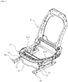
- a seat frame S is provided to be slide-adjustable frontward and rearward by using a pair of right and left seat slide adjusters 10, 10 of this embodiment disposed at a predetermined distance in a width direction of a vehicle body.
- a slide lever 17 Under a front edge portion of a seat cushion frame S1, a slide lever 17 extending between the seat slide adjusters 10, 10 disposed on the right and left is disposed.
- the slide lever 17 connects release levers 161, 161 of later-described locking mechanisms 16, 16 provided in the right and left seat slide adjusters 10, 10 with each other, and has a structure in which a person operates the slide lever 17 to thereby release a lock.
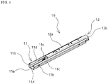
- FIG. 4 to FIGs. 8 only one of the seat slide adjusters 10 is illustrated to describe its detailed structure, but both of the right and left seat slide adjusters 10, 10 illustrated in FIG. 1 to FIG. 3 have the same structure.
- the seat slide adjuster 10 of this embodiment includes a lower rail 11, an upper rail 12 slidable in a longitudinal direction of the lower rail 11, and the like, the lower rail 11 is fixed to a vehicle body floor, and a side frame S11 of the seat cushion frame S1 of the seat frame S is coupled to the upper rail 12.
- the lower rail 11 has a bottom wall portion 11a, a pair of vertical wall portions 11b, 11b standing up from both sides of the bottom wall portion 11a and facing each other, a pair of upper wall portions 11c, 11c which are bent inward with respect to each other from upper edges of the vertical wall portions 11b, 11b, and simultaneously, whose facing edges are separated from each other at a predetermined distance, and inner wall portions 11d, 11d bent downward from inner edges of the upper wall portions 11c, 11c, and is formed in a substantially squared U shape with an upper surface open in a cross section in the width direction orthogonal to the longitudinal direction (refer to FIG. 4 , FIG. 5 and FIGs. 7(a), (b) ).
- the upper rail 12 is formed in a substantially squared U shape with a lower surface open in the cross section in the width direction, which has an upper wall portion 12a and a pair of sidewall portions 12b, 12b bent downward from both sides of the upper wall portion 12a and facing each other. Further, from lower end portions of the sidewall portions 12b, 12b, bottom wall portions 12c, 12c bent outward with a predetermined width in a substantially horizontal direction are formed respectively, and moreover, vertical wall portions 12d, 12d folded back upward are formed from outer edges of the bottom wall portions 12c, 12c (refer to FIG. 4 , FIG. 5 and FIGs. 7(a), (b) ).
- the vertical wall portions 12d, 12d of the upper rail 12 face the vertical wall portions 11b, 11b of the lower rail 11 respectively, the vertical wall portions 12d, 12d of the upper rail 12 are positioned and disposed between the vertical wall portions 11b, 11b and the inner wall portions 11d, 11d of the lower rail 11 (refer to FIGs. 7(a), (b) ).
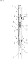
- sliding resistance reducing members 14, 15 are interposed between the lower rail 11 and the upper rail 12, as illustrated in FIG. 5 , FIG. 6 , and FIGs. 7(a), (b) .
- the sliding resistance reducing members 14, 15 are preferably provided in plurality at a predetermined distance in the longitudinal direction of the lower rail 11, and in this embodiment, provided close to a front portion and close to a rear portion of the lower rail 11.
- a pair of the sliding resistance reducing members (hereinafter, "front-side sliding resistance reducing members") 14, 14 disposed close to the front portion are provided to substantially face each other with a center Z in the width direction of the lower rail 11 sandwiched and to respectively correspond to the right and left vertical wall portions 11b, 11b of the lower rail 11, as illustrated in FIG. 7(a) .
- front-side sliding resistance reducing members hereinafter, "front-side sliding resistance reducing members" 14, 14 disposed close to the front portion are provided to substantially face each other with a center Z in the width direction of the lower rail 11 sandwiched and to respectively correspond to the right and left vertical wall portions 11b, 11b of the lower rail 11, as illustrated in FIG. 7(a) .
- the front-side sliding resistance reducing members 14, 14 are each in a substantially L shape in the cross section along the width direction, and simultaneously, have retainers (front-side retainers) 141, 141 the length along the longitudinal direction of the lower rail 11 of each of which is several cm (normally about 2 to 5 cm though it depends on a size of the seat slide adjuster 10).
- the front-side retainers 141 141 each in the substantially L shape in the cross section have first retaining wall portions 1411, 1411 extending in a vertical direction and second retaining wall portions 1412, 1412 extending in a lateral direction from lower portions of the first retaining wall portions 1411, 1411 toward the center in the width direction of the lower rail 11.
- the front-side sliding resistance reducing members 14, 14 are preferably formed of a synthetic resin, and have flexibility in which the first retaining wall portions 1411, 1411 bend relatively to the second retaining wall portions 1412, 1412.
- the front-side retainers 141, 141 are disposed in a manner that the first retaining wall portions 1411, 1411 are positioned between the vertical wall portions 11b, 11b of the lower rail 11 and the vertical wall portions 12d, 12d of the upper rail 12, and the second retaining wall portions 1412, 1412 are positioned between the bottom wall portion 11a of the lower rail 11 and the bottom wall portions 12c, 12c of the upper rail 12.
- first retaining wall portions 1411, 1411 ball member retaining portions 1411a, 1411a are each formed at one or more points.
- the ball member retaining portions 1411a, 1411a are each formed at two points along the longitudinal direction of the lower rail 11, and in the respective ones, first ball members 142, 142 are rotatably disposed.
- the vicinity of a portion where the ball member retaining portions 1411a, 1411a are each formed bulges in thickness directions, and the ball member retaining portions 1411a, 1411a are each formed of holes obtained by penetrating the bulging portion in the thickness directions.
- ball member retaining portions 1412a, 1412a are each formed at one or more points.
- the ball member retaining portions 1412a, 1412a are each formed at two points along the longitudinal direction of the lower rail 11.
- second ball members 143, 143 are rotatably disposed in the ball member retaining portions 1412a, 1412a of the second retaining wall portions 1412, 1412.
- the vicinity of a portion where the ball member retaining portions 1412a, 1412a are each formed bulges in thickness directions, and the ball member retaining portions 1412a, 1412a are each formed of holes obtained by penetrating the bulging portion in the thickness directions.
- the holes have a diameter at open ends smaller than a diameter of the second ball members 143, 143, and the second ball members 143, 143 each face the outside from the open ends and they are in contact with the bottom wall portion 11a of the lower rail 11 and the bottom wall portions 12c, 12c of the upper rail 12 to be rotatable.
- the first ball members 142, 142 disposed in the first retaining wall portions 1411, 1411 are supported in positions apart from both the upper wall portions 11c, 11c and the bottom wall portion 11a of the lower rail 11 in ranges of the vertical wall portions 11b, 11b of the lower rail 11, and the second ball members 143, 143 are supported in positions apart from the vertical wall portions 11b, 11b of the lower rail 11 each toward the center Z in the width direction.
- first retaining wall portions 1411, 1411 and the second retaining wall portions 1412, 1412, and, the ball member retaining portions 1411a, 1411a, 1412a, 1412a formed therein of the retainers 141, 141 each in the substantially L shape in the cross section are formed in a size having such a positional relationship as described above when disposed between the lower rail 11 and the upper rail 12.
- middle portions 11b1, 11b1 apart from both the upper wall portions 11c, 11c and the bottom wall portion 11a of the lower rail 11 are formed to bulge outward, and middle portions 12d1, 12d, of the vertical wall portions 12d, 12d of the upper rail 12 corresponding thereto are formed to bulge inward. This causes the ball members 142, 142 to be disposed at predetermined positions.
- first ball members 142, 142 are disposed to be sandwiched between the middle portions 11b1, 11b1 bulging outward in the vertical wall portions 11b of the lower rail 11 and the middle portions 12d1, 12d1 bulging inward in the vertical wall portions 12d of the upper rail 12, and thereby rigidity in the lateral direction of the lower rail 11 and the upper rail 12 is supplemented by the first ball members 142, 142.
- a diameter of the first ball members 142, 142 is preferably larger than a diameter of the second ball members.
- a pair of the sliding resistance reducing members (hereinafter, "rear-side sliding resistance reducing members”) 15, 15 disposed close to the rear portion are also provided to substantially face each other with the center in the width direction of the lower rail 11 sandwiched and to respectively correspond to the right and left vertical wall portions 11b, 11b of the lower rail 11, similarly to the front-side sliding resistance reducing members 14, 14, as illustrated in FIG. 7(b) .
- the rear-side sliding resistance reducing members 15, 15 have almost the same structure as that of the front-side sliding resistance reducing members 14, 14, have retainers (rear-side retainers) 151, 151 the cross section in the width direction of each of which is in a substantially L shape and the length along the longitudinal direction of the lower rail 11 of each of which is also the same, and have first retaining wall portions 1511, 1511 extending in the vertical direction and second retaining wall portions 1512, 1512 extending in the lateral direction from lower portions of the first retaining wall portions 1511, 1511 toward the center Z in the width direction of the lower rail 11. Further, it is the same that they are preferably formed of a synthetic resin and have flexibility, and the first retaining wall portions 1511, 1511 bend relatively to the second retaining wall portions 1512, 1512.
- the rear-side retainers 151, 151 are also disposed in a manner that the first retaining wall portions 1511, 1511 are positioned between the vertical wall portions 11b, 11b of the lower rail 11 and the vertical wall portions 12d, 12d of the upper rail 12, and the second retaining wall portions 1512, 1512 are positioned between the bottom wall portion 11a of the lower rail 11 and the bottom wall portions 12c, 12c of the upper rail 12.
- first retaining wall portions 1511, 1511 of the rear-side retainers 151, 151 ball member retaining portions 1511a, 1511a are each formed at one or more points, and in this embodiment, each formed at two points along the longitudinal direction of the lower rail 11. Then, in the respective ones, first ball members 152, 152 are rotatably disposed in contact with the vertical wall portions 11b, 11b of the lower rail 11 and the vertical wall portions 12d, 12d of the upper rail 12. Further, also in the second retaining wall portions 1512, 1512, ball member retaining portions 1512a, 1512a are each formed at one or more points.
- first retaining wall portions 1511, 1511 and the second retaining wall portions 1512, 1512, and, the ball member retaining portions 1511a, 1511a, 1512a, 1512a formed therein of the retainers 151, 151 each in the substantially L shape in the cross section are formed in a size having such a positional relationship as described above when disposed between the lower rail 11 and the upper rail 12. These points are also the same as those in the front-side sliding resistance reducing members 14, 14.
- first ball members 152, 152 are sandwiched and disposed between middle portions 11b1, 11b1 bulging outward in the vertical wall portions 11b of the lower rail 11 and middle portions 12d1, 12d1 bulging inward in the vertical wall portions 12d of the upper rail 12, and the first ball members 152, 152 and the second ball members 153, 153 are supported through the retainers 151, 151 each in the substantially L shape in the cross section, and thereby the rigidity in the lateral direction of the lower rail 11 and the upper rail 12 is enhanced.
- the ball member retaining portions 1512a, 1512a of the second retaining wall portions 1512, 1512 of the rear-side retainers 151, 151 are each formed at three points in this embodiment. Specifically, they are first each formed at two points along the longitudinal direction of the lower rail 11 in positions apart by a predetermined distance from the vertical wall portions 11b, 11b of the lower rail 11 toward the center Z in the width direction of the lower rail 11, and simultaneously, further each formed at one point close to the center in the width direction of the lower rail 11.
- the second retaining wall portions 1512, 1512 of the rear-side retainers 151, 151 each have a shape which is a substantially triangle in plan view and whose top side goes toward the center Z in the width direction of the lower rail 11.
- the second ball members 153, 153 are each disposed at these three points of each of the ball member retaining portions 1512a, 1512a formed in the second retaining wall portions 1512, 1512 to be disposed in a total of three. A larger load is imposed close to the rear portion than close to the front portion by about 10 to 30% on the seat slide adjuster 10.
- the number of the second ball members 153, 153 disposed in the second retaining wall portions 1512, 1512 of the rear-side retainers 151, 151 is preferably larger than that of the second ball members 143, 143 disposed in the front-side retainers 141, 141 to disperse a bearing pressure.
- the seat slide adjuster 10 of this embodiment has the above-described sliding resistance reducing members 14, 15.
- Both the front-side retainers 141, 141 and the rear-side retainers 151, 151 are each in the substantially L shape in the cross section, and respectively have the first retaining wall portions 1411, 1411, 1511, 1511 in which the first ball members 142, 142, 152, 152 are disposed and the second retaining wall portions 1412, 1412, 1512, 1512 in which the second ball members 143, 143, 153, 153 are disposed.
- the second retaining wall portions 1412, 1412, 1512, 1512 are disposed between the bottom wall portion 11a of the lower rail 11 and the bottom wall portions 12c, 12c of the upper rail 12, and the first retaining wall portions 1411, 1411, 1511, 1511 are disposed between the vertical wall portions 11b, 11b of the lower rail 11 and the vertical wall portions 12d, 12d of the upper rail 12.
- first ball members 142, 142, 152, 152 are supported in the positions apart from both the upper wall portions 11c, 11c and the bottom wall portion 11a of the lower rail 11 in the ranges of the vertical wall portions 11b, 11b of the lower rail 11, and the second ball members 143, 143, 153, 153 are supported in the positions apart from the vertical wall portions 11b, 11b of the lower rail 11 each toward the center Z in the width direction.
- first ball members 142, 142, 152, 152 do not correspond to such portions having high rigidity as corner portions between the vertical wall portions 11b, 11b and the upper wall portions 11c, 11c of the lower rail 11 and corner portions between the vertical wall portions 11b, 11b and the bottom wall portion 11a of the lower rail 11, but are disposed in positions having lower rigidity at the middles of them.
- the second ball members 143, 143, 153, 153 are respectively connected to the first ball members 142, 142, 152, 152 by the retainers 141, 141, 151, 151 each in the substantially L shape in the cross section.
- the larger diameter of the first ball members 142, 142, 152, 152 than the diameter of the second ball members 143, 143, 153, 153 as described above allows such rigidity in the lateral direction to be secured higher.
- the second ball members 143, 143, 153, 153 receive the force in the up-down direction.
- the upper rail 12 and the lower rail 11 receive the force through deflections in the sidewall portions 12b, 12b of the upper rail 12 and a middle range in the bottom wall portion 11a of the lower rail 11 which do not directly correspond to disposed positions of the sliding resistance reducing members 14, 15. Therefore, rattling between the upper rail 12 and the lower rail 11 is eliminated and smoothness at the time of sliding is secured, which enables prevention of abnormal sound.
- sliding resistance reducing members 14, 15 of this embodiment causes the occurrence of rattling and abnormal sound at the time when the external force is loaded to be suppressed, and the first ball members 142, 142, 152, 152 and the second ball members 143, 143, 153, 153 to roll with respect to surfaces of the vertical wall portions 12d, 12d and the bottom wall portions 12c, 12c of the upper rail 12 also at the time of sliding, resulting in a configuration capable of securing high slidability.
- the sliding resistance reducing members 14, 15 of this embodiment have a function of supplementing the rigidity of the lower rail 11 and the upper rail 12, and allow a thinner material even in the same one to be used as a raw material forming the lower rail 11 and the upper rail 12, resulting in enabling a contribution to a reduction in weight of the seat slide adjuster 10.
- a reference sign 16 indicates a locking mechanism.
- the locking mechanism 16 includes a release lever 161 and a lock member 162.
- the release lever 161 has a predetermined length and is disposed inside the lower rail 11 and the upper rail 12.
- a front end portion 161a of the release lever 161 protrudes from a front end of the upper rail 12, and the above-described slide lever 17 to be operated by a person is coupled to the front end portion 161a.
- up and down displacements of the front end portion 161a cause displacements of a rear end portion 161b in the opposite directions centered at a middle portion in the longitudinal direction.
- the slide lever 17 is lifted upward to displace the front end portion 161a of the release lever 161 upward, which causes the engaging portion 162b of the lock member 162 to separate from the portion to be engaged 11e to be in an unlocked state, resulting in enabling frontward and rearward slide movement.
- a displacement of the release lever 161 in the opposite direction causes the engaging portion 162b to engage in the portion to be engaged 11e to be in a locked state, and the movement in the opposite direction is made by elastic force of a leaf spring member 163 which biases the release lever 161 in an engaging direction.
- the seat slide adjuster of the present invention is suitably used in automobiles as described in the above embodiment, and also applicable to a seat for various vehicles such as airplanes, trains, ships, and buses.
Landscapes
- Engineering & Computer Science (AREA)
- Aviation & Aerospace Engineering (AREA)
- Transportation (AREA)
- Mechanical Engineering (AREA)
- Seats For Vehicles (AREA)
Applications Claiming Priority (2)
| Application Number | Priority Date | Filing Date | Title |
|---|---|---|---|
| JP2019141841A JP7387137B2 (ja) | 2019-07-31 | 2019-07-31 | シートスライドアジャスタ |
| PCT/JP2020/029544 WO2021020578A1 (fr) | 2019-07-31 | 2020-07-31 | Dispositif de réglage de glissière de siège |
Publications (3)
| Publication Number | Publication Date |
|---|---|
| EP4005867A1 true EP4005867A1 (fr) | 2022-06-01 |
| EP4005867A4 EP4005867A4 (fr) | 2022-08-10 |
| EP4005867B1 EP4005867B1 (fr) | 2026-04-22 |
Family
ID=74228938
Family Applications (1)
| Application Number | Title | Priority Date | Filing Date |
|---|---|---|---|
| EP20847867.7A Active EP4005867B1 (fr) | 2019-07-31 | 2020-07-31 | Dispositif de réglage de glissière de siège |
Country Status (5)
| Country | Link |
|---|---|
| US (1) | US11833934B2 (fr) |
| EP (1) | EP4005867B1 (fr) |
| JP (1) | JP7387137B2 (fr) |
| CN (1) | CN114025989B (fr) |
| WO (1) | WO2021020578A1 (fr) |
Families Citing this family (1)
| Publication number | Priority date | Publication date | Assignee | Title |
|---|---|---|---|---|
| US12145478B2 (en) * | 2020-10-30 | 2024-11-19 | Ts Tech Co., Ltd. | Seat rail assembly |
Family Cites Families (35)
| Publication number | Priority date | Publication date | Assignee | Title |
|---|---|---|---|---|
| JP3565530B2 (ja) | 1996-06-30 | 2004-09-15 | 株式会社タチエス | 車両用シートのスライドレール |
| DE69832435T2 (de) * | 1997-05-13 | 2006-08-17 | Delta Kogyo Co. Ltd. | Fahrzeugsitzverstellschienen |
| JP2000233671A (ja) | 1999-02-16 | 2000-08-29 | Delta Kogyo Co Ltd | スライダーの剥離防止構造 |
| KR20030088214A (ko) * | 2002-05-13 | 2003-11-19 | (주) 신형엔지니어링 | 자동차용 시트레일 조립방법 및 조립을 위한 가공장치 |
| US7314204B2 (en) * | 2005-09-27 | 2008-01-01 | Kabushikigaisha Imasen Denki Seisakusho | Sliding rail system |
| JP4797625B2 (ja) * | 2005-12-28 | 2011-10-19 | アイシン精機株式会社 | 車両用シートスライド装置 |
| JP5085900B2 (ja) | 2006-08-15 | 2012-11-28 | シロキ工業株式会社 | シートトラック装置 |
| JP5080176B2 (ja) * | 2007-08-31 | 2012-11-21 | 富士機工株式会社 | シートスライド装置 |
| JP2009101955A (ja) * | 2007-10-25 | 2009-05-14 | Aisin Seiki Co Ltd | 車両用シートスライド装置 |
| DE102008056683B4 (de) * | 2008-11-07 | 2012-09-13 | Keiper Gmbh & Co. Kg | Längseinsteller für einen Fahrzeugsitz |
| JP5327002B2 (ja) * | 2009-11-05 | 2013-10-30 | アイシン精機株式会社 | 車両用シートスライド装置 |
| JP2011245956A (ja) * | 2010-05-26 | 2011-12-08 | Imasen Electric Ind Co Ltd | シートスライド装置 |
| JP5592191B2 (ja) * | 2010-08-09 | 2014-09-17 | シロキ工業株式会社 | シートトラック |
| KR101206802B1 (ko) * | 2011-04-21 | 2012-11-30 | 주식회사 오스템 | 시트트랙 |
| DE102011115948B3 (de) * | 2011-10-12 | 2013-01-24 | Keiper Gmbh & Co. Kg | Längseinstellbarer Fahrzeugsitz |
| JP6028614B2 (ja) * | 2013-02-19 | 2016-11-16 | アイシン精機株式会社 | 車両用シートスライド装置 |
| JP6089759B2 (ja) * | 2013-02-19 | 2017-03-08 | アイシン精機株式会社 | 車両用シートスライド装置 |
| JP6253937B2 (ja) * | 2013-09-30 | 2017-12-27 | トヨタ紡織株式会社 | 乗物用シート |
| JP6217501B2 (ja) * | 2014-02-05 | 2017-10-25 | トヨタ紡織株式会社 | スライドレール |
| US10518666B2 (en) * | 2014-10-14 | 2019-12-31 | Saint-Gobain Performance Plastics Pampus Gmbh | Linear motion assemblies and bearings for use in linear motion assemblies |
| CN204605569U (zh) * | 2015-04-23 | 2015-09-02 | 曹小静 | 一种用于车辆座椅的导轨装置 |
| WO2016181815A1 (fr) * | 2015-05-09 | 2016-11-17 | デルタ工業株式会社 | Dispositif de réglage de glissière de siège |
| DE102016212168B4 (de) * | 2016-07-04 | 2020-08-06 | Adient Luxembourg Holding S.À R.L. | Längseinsteller sowie fahrzeugsitz |
| JP2018012408A (ja) * | 2016-07-20 | 2018-01-25 | アイシン精機株式会社 | 車両用シートスライド装置 |
| JP6702055B2 (ja) * | 2016-07-22 | 2020-05-27 | トヨタ紡織株式会社 | シート用スライド装置 |
| US10486554B2 (en) * | 2016-09-08 | 2019-11-26 | Fisher & Company, Inc. | Power seat length adjuster assembly and method of manufacture |
| JP6861491B2 (ja) * | 2016-09-16 | 2021-04-21 | シロキ工業株式会社 | シートトラック |
| DE102016225818B4 (de) * | 2016-09-21 | 2021-05-12 | Adient Luxembourg Holding S.À R.L. | Längseinsteller sowie Fahrzeugsitz |
| DE102016225822A1 (de) * | 2016-09-21 | 2018-03-22 | Adient Luxembourg Holding S.a.r.l. | Sitzschienenpaar für einen Fahrzeugsitz |
| JP6904848B2 (ja) | 2016-09-30 | 2021-07-21 | 株式会社Tf−Metal | シートスライド装置 |
| WO2018062076A1 (fr) | 2016-09-30 | 2018-04-05 | Tf-Metal Co., Ltd. | Dispositif de coulisse de siège |
| DE102017218492B4 (de) * | 2017-08-08 | 2022-12-22 | Keiper Seating Mechanisms Co., Ltd. | Längseinsteller und fahrzeugsitz |
| JP7107823B2 (ja) * | 2018-12-04 | 2022-07-27 | 株式会社Tf-Metal | 電動式シートスライド装置 |
| US20200282870A1 (en) * | 2019-03-07 | 2020-09-10 | Hsin Chong Machinery Works Co. Ltd. | Electric drive mechanism of seat rail |
| JP7527990B2 (ja) * | 2021-01-22 | 2024-08-05 | 株式会社Tf-Metal | シートスライド装置及びシートスライド装置の製造方法 |
-
2019
- 2019-07-31 JP JP2019141841A patent/JP7387137B2/ja active Active
-
2020
- 2020-07-31 CN CN202080047737.2A patent/CN114025989B/zh active Active
- 2020-07-31 WO PCT/JP2020/029544 patent/WO2021020578A1/fr not_active Ceased
- 2020-07-31 US US17/631,339 patent/US11833934B2/en active Active
- 2020-07-31 EP EP20847867.7A patent/EP4005867B1/fr active Active
Also Published As
| Publication number | Publication date |
|---|---|
| JP2021024341A (ja) | 2021-02-22 |
| EP4005867B1 (fr) | 2026-04-22 |
| EP4005867A4 (fr) | 2022-08-10 |
| JP7387137B2 (ja) | 2023-11-28 |
| CN114025989A (zh) | 2022-02-08 |
| US20220281359A1 (en) | 2022-09-08 |
| US11833934B2 (en) | 2023-12-05 |
| CN114025989B (zh) | 2024-06-11 |
| WO2021020578A1 (fr) | 2021-02-04 |
Similar Documents
| Publication | Publication Date | Title |
|---|---|---|
| JP6195746B2 (ja) | シートスライド装置 | |
| US9616777B2 (en) | Vehicle seat | |
| US9764660B2 (en) | Slide rail | |
| EP2292462B1 (fr) | Structure coulissante de siège de véhicule | |
| US20090134686A1 (en) | Vehicle seat | |
| JP5275622B2 (ja) | 車両用シート | |
| KR20100044775A (ko) | 래치 메커니즘 | |
| US20120181408A1 (en) | Vehicle seat slide mechanism | |
| CN108058621A (zh) | 车辆座椅 | |
| EP4005867B1 (fr) | Dispositif de réglage de glissière de siège | |
| EP1721776A2 (fr) | Glissière de véhicule | |
| JP6739802B2 (ja) | シートスライドアジャスタ | |
| US12179639B2 (en) | Seat sliding device and slide lever connecting structure in the seat sliding device | |
| JP2016094101A (ja) | スライドレール | |
| JP6844473B2 (ja) | シート支持装置 | |
| KR20240050159A (ko) | 차량용 시트 슬라이딩 장치 | |
| JP2004025940A (ja) | 乗り物用シート | |
| JPH10203208A (ja) | スライドレール装置 | |
| JP2016055839A (ja) | スライドレール | |
| JPH0632172U (ja) | シートサスペンション装置 | |
| JP2015202795A (ja) | スライドレール | |
| WO2008010615A1 (fr) | Rail de siège pour véhicule |
Legal Events
| Date | Code | Title | Description |
|---|---|---|---|
| STAA | Information on the status of an ep patent application or granted ep patent |
Free format text: STATUS: THE INTERNATIONAL PUBLICATION HAS BEEN MADE |
|
| PUAI | Public reference made under article 153(3) epc to a published international application that has entered the european phase |
Free format text: ORIGINAL CODE: 0009012 |
|
| STAA | Information on the status of an ep patent application or granted ep patent |
Free format text: STATUS: REQUEST FOR EXAMINATION WAS MADE |
|
| 17P | Request for examination filed |
Effective date: 20220215 |
|
| AK | Designated contracting states |
Kind code of ref document: A1 Designated state(s): AL AT BE BG CH CY CZ DE DK EE ES FI FR GB GR HR HU IE IS IT LI LT LU LV MC MK MT NL NO PL PT RO RS SE SI SK SM TR |
|
| A4 | Supplementary search report drawn up and despatched |
Effective date: 20220707 |
|
| RIC1 | Information provided on ipc code assigned before grant |
Ipc: B60N 2/07 20060101AFI20220701BHEP |
|
| DAV | Request for validation of the european patent (deleted) | ||
| DAX | Request for extension of the european patent (deleted) | ||
| STAA | Information on the status of an ep patent application or granted ep patent |
Free format text: STATUS: EXAMINATION IS IN PROGRESS |
|
| 17Q | First examination report despatched |
Effective date: 20240918 |
|
| GRAP | Despatch of communication of intention to grant a patent |
Free format text: ORIGINAL CODE: EPIDOSNIGR1 |
|
| STAA | Information on the status of an ep patent application or granted ep patent |
Free format text: STATUS: GRANT OF PATENT IS INTENDED |
|
| INTG | Intention to grant announced |
Effective date: 20251211 |
|
| GRAS | Grant fee paid |
Free format text: ORIGINAL CODE: EPIDOSNIGR3 |
|
| GRAA | (expected) grant |
Free format text: ORIGINAL CODE: 0009210 |
|
| STAA | Information on the status of an ep patent application or granted ep patent |
Free format text: STATUS: THE PATENT HAS BEEN GRANTED |
|
| AK | Designated contracting states |
Kind code of ref document: B1 Designated state(s): AL AT BE BG CH CY CZ DE DK EE ES FI FR GB GR HR HU IE IS IT LI LT LU LV MC MK MT NL NO PL PT RO RS SE SI SK SM TR |
|
| REG | Reference to a national code |
Ref country code: CH Ref legal event code: F10 Free format text: ST27 STATUS EVENT CODE: U-0-0-F10-F00 (AS PROVIDED BY THE NATIONAL OFFICE) Effective date: 20260422 Ref country code: GB Ref legal event code: FG4D |
|
| P01 | Opt-out of the competence of the unified patent court (upc) registered |
Free format text: CASE NUMBER: UPC_APP_0010575_4005867/2026 Effective date: 20260320 |