EP4006182A1 - Procédé de formation d'une rainure linéaire et procédé de formation d'une tôle d'acier électrique à grains orientés - Google Patents
Procédé de formation d'une rainure linéaire et procédé de formation d'une tôle d'acier électrique à grains orientés Download PDFInfo
- Publication number
- EP4006182A1 EP4006182A1 EP20846730.8A EP20846730A EP4006182A1 EP 4006182 A1 EP4006182 A1 EP 4006182A1 EP 20846730 A EP20846730 A EP 20846730A EP 4006182 A1 EP4006182 A1 EP 4006182A1
- Authority
- EP
- European Patent Office
- Prior art keywords
- steel sheet
- laser
- laser beams
- resist
- forming
- Prior art date
- Legal status (The legal status is an assumption and is not a legal conclusion. Google has not performed a legal analysis and makes no representation as to the accuracy of the status listed.)
- Pending
Links
Images


Classifications
-
- C—CHEMISTRY; METALLURGY
- C21—METALLURGY OF IRON
- C21D—MODIFYING THE PHYSICAL STRUCTURE OF FERROUS METALS; GENERAL DEVICES FOR HEAT TREATMENT OF FERROUS OR NON-FERROUS METALS OR ALLOYS; MAKING METAL MALLEABLE, e.g. BY DECARBURISATION OR TEMPERING
- C21D8/00—Modifying the physical properties of ferrous metals or ferrous alloys by deformation combined with, or followed by, heat treatment
- C21D8/12—Modifying the physical properties of ferrous metals or ferrous alloys by deformation combined with, or followed by, heat treatment during manufacturing of articles with special electromagnetic properties
- C21D8/1294—Modifying the physical properties of ferrous metals or ferrous alloys by deformation combined with, or followed by, heat treatment during manufacturing of articles with special electromagnetic properties involving a localised treatment
-
- B—PERFORMING OPERATIONS; TRANSPORTING
- B23—MACHINE TOOLS; METAL-WORKING NOT OTHERWISE PROVIDED FOR
- B23K—SOLDERING OR UNSOLDERING; WELDING; CLADDING OR PLATING BY SOLDERING OR WELDING; CUTTING BY APPLYING HEAT LOCALLY, e.g. FLAME CUTTING; WORKING BY LASER BEAM
- B23K26/00—Working by laser beam, e.g. welding, cutting or boring
- B23K26/36—Removing material
- B23K26/362—Laser etching
-
- B—PERFORMING OPERATIONS; TRANSPORTING
- B23—MACHINE TOOLS; METAL-WORKING NOT OTHERWISE PROVIDED FOR
- B23K—SOLDERING OR UNSOLDERING; WELDING; CLADDING OR PLATING BY SOLDERING OR WELDING; CUTTING BY APPLYING HEAT LOCALLY, e.g. FLAME CUTTING; WORKING BY LASER BEAM
- B23K26/00—Working by laser beam, e.g. welding, cutting or boring
- B23K26/02—Positioning or observing the workpiece, e.g. with respect to the point of impact; Aligning, aiming or focusing the laser beam
- B23K26/06—Shaping the laser beam, e.g. by masks or multi-focusing
- B23K26/0604—Shaping the laser beam, e.g. by masks or multi-focusing by a combination of beams
-
- B—PERFORMING OPERATIONS; TRANSPORTING
- B23—MACHINE TOOLS; METAL-WORKING NOT OTHERWISE PROVIDED FOR
- B23K—SOLDERING OR UNSOLDERING; WELDING; CLADDING OR PLATING BY SOLDERING OR WELDING; CUTTING BY APPLYING HEAT LOCALLY, e.g. FLAME CUTTING; WORKING BY LASER BEAM
- B23K26/00—Working by laser beam, e.g. welding, cutting or boring
- B23K26/02—Positioning or observing the workpiece, e.g. with respect to the point of impact; Aligning, aiming or focusing the laser beam
- B23K26/06—Shaping the laser beam, e.g. by masks or multi-focusing
- B23K26/067—Dividing the beam into multiple beams, e.g. multi-focusing
-
- B—PERFORMING OPERATIONS; TRANSPORTING
- B23—MACHINE TOOLS; METAL-WORKING NOT OTHERWISE PROVIDED FOR
- B23K—SOLDERING OR UNSOLDERING; WELDING; CLADDING OR PLATING BY SOLDERING OR WELDING; CUTTING BY APPLYING HEAT LOCALLY, e.g. FLAME CUTTING; WORKING BY LASER BEAM
- B23K26/00—Working by laser beam, e.g. welding, cutting or boring
- B23K26/08—Devices involving relative movement between laser beam and workpiece
- B23K26/083—Devices involving movement of the workpiece in at least one axial direction
- B23K26/0838—Devices involving movement of the workpiece in at least one axial direction by using an endless conveyor belt
- B23K26/0846—Devices involving movement of the workpiece in at least one axial direction by using an endless conveyor belt for moving elongated workpieces longitudinally, e.g. wire or strip material
-
- B—PERFORMING OPERATIONS; TRANSPORTING
- B23—MACHINE TOOLS; METAL-WORKING NOT OTHERWISE PROVIDED FOR
- B23K—SOLDERING OR UNSOLDERING; WELDING; CLADDING OR PLATING BY SOLDERING OR WELDING; CUTTING BY APPLYING HEAT LOCALLY, e.g. FLAME CUTTING; WORKING BY LASER BEAM
- B23K26/00—Working by laser beam, e.g. welding, cutting or boring
- B23K26/08—Devices involving relative movement between laser beam and workpiece
- B23K26/0869—Devices involving movement of the laser head in at least one axial direction
-
- B—PERFORMING OPERATIONS; TRANSPORTING
- B23—MACHINE TOOLS; METAL-WORKING NOT OTHERWISE PROVIDED FOR
- B23K—SOLDERING OR UNSOLDERING; WELDING; CLADDING OR PLATING BY SOLDERING OR WELDING; CUTTING BY APPLYING HEAT LOCALLY, e.g. FLAME CUTTING; WORKING BY LASER BEAM
- B23K26/00—Working by laser beam, e.g. welding, cutting or boring
- B23K26/36—Removing material
- B23K26/361—Removing material for deburring or mechanical trimming
-
- B—PERFORMING OPERATIONS; TRANSPORTING
- B23—MACHINE TOOLS; METAL-WORKING NOT OTHERWISE PROVIDED FOR
- B23K—SOLDERING OR UNSOLDERING; WELDING; CLADDING OR PLATING BY SOLDERING OR WELDING; CUTTING BY APPLYING HEAT LOCALLY, e.g. FLAME CUTTING; WORKING BY LASER BEAM
- B23K26/00—Working by laser beam, e.g. welding, cutting or boring
- B23K26/36—Removing material
- B23K26/362—Laser etching
- B23K26/364—Laser etching for making a groove or trench, e.g. for scribing a break initiation groove
-
- B—PERFORMING OPERATIONS; TRANSPORTING
- B23—MACHINE TOOLS; METAL-WORKING NOT OTHERWISE PROVIDED FOR
- B23K—SOLDERING OR UNSOLDERING; WELDING; CLADDING OR PLATING BY SOLDERING OR WELDING; CUTTING BY APPLYING HEAT LOCALLY, e.g. FLAME CUTTING; WORKING BY LASER BEAM
- B23K26/00—Working by laser beam, e.g. welding, cutting or boring
- B23K26/36—Removing material
- B23K26/40—Removing material taking account of the properties of the material involved
-
- C—CHEMISTRY; METALLURGY
- C21—METALLURGY OF IRON
- C21D—MODIFYING THE PHYSICAL STRUCTURE OF FERROUS METALS; GENERAL DEVICES FOR HEAT TREATMENT OF FERROUS OR NON-FERROUS METALS OR ALLOYS; MAKING METAL MALLEABLE, e.g. BY DECARBURISATION OR TEMPERING
- C21D8/00—Modifying the physical properties of ferrous metals or ferrous alloys by deformation combined with, or followed by, heat treatment
- C21D8/12—Modifying the physical properties of ferrous metals or ferrous alloys by deformation combined with, or followed by, heat treatment during manufacturing of articles with special electromagnetic properties
-
- C—CHEMISTRY; METALLURGY
- C21—METALLURGY OF IRON
- C21D—MODIFYING THE PHYSICAL STRUCTURE OF FERROUS METALS; GENERAL DEVICES FOR HEAT TREATMENT OF FERROUS OR NON-FERROUS METALS OR ALLOYS; MAKING METAL MALLEABLE, e.g. BY DECARBURISATION OR TEMPERING
- C21D9/00—Heat treatment, e.g. annealing, hardening, quenching or tempering, adapted for particular articles; Furnaces therefor
- C21D9/46—Heat treatment, e.g. annealing, hardening, quenching or tempering, adapted for particular articles; Furnaces therefor for sheet metals
-
- C—CHEMISTRY; METALLURGY
- C22—METALLURGY; FERROUS OR NON-FERROUS ALLOYS; TREATMENT OF ALLOYS OR NON-FERROUS METALS
- C22C—ALLOYS
- C22C38/00—Ferrous alloys, e.g. steel alloys
- C22C38/002—Ferrous alloys, e.g. steel alloys containing In, Mg, or other elements not provided for in one single group C22C38/001 - C22C38/60
-
- C—CHEMISTRY; METALLURGY
- C22—METALLURGY; FERROUS OR NON-FERROUS ALLOYS; TREATMENT OF ALLOYS OR NON-FERROUS METALS
- C22C—ALLOYS
- C22C38/00—Ferrous alloys, e.g. steel alloys
- C22C38/008—Ferrous alloys, e.g. steel alloys containing tin
-
- C—CHEMISTRY; METALLURGY
- C22—METALLURGY; FERROUS OR NON-FERROUS ALLOYS; TREATMENT OF ALLOYS OR NON-FERROUS METALS
- C22C—ALLOYS
- C22C38/00—Ferrous alloys, e.g. steel alloys
- C22C38/02—Ferrous alloys, e.g. steel alloys containing silicon
-
- C—CHEMISTRY; METALLURGY
- C22—METALLURGY; FERROUS OR NON-FERROUS ALLOYS; TREATMENT OF ALLOYS OR NON-FERROUS METALS
- C22C—ALLOYS
- C22C38/00—Ferrous alloys, e.g. steel alloys
- C22C38/04—Ferrous alloys, e.g. steel alloys containing manganese
-
- C—CHEMISTRY; METALLURGY
- C22—METALLURGY; FERROUS OR NON-FERROUS ALLOYS; TREATMENT OF ALLOYS OR NON-FERROUS METALS
- C22C—ALLOYS
- C22C38/00—Ferrous alloys, e.g. steel alloys
- C22C38/06—Ferrous alloys, e.g. steel alloys containing aluminium
-
- C—CHEMISTRY; METALLURGY
- C22—METALLURGY; FERROUS OR NON-FERROUS ALLOYS; TREATMENT OF ALLOYS OR NON-FERROUS METALS
- C22C—ALLOYS
- C22C38/00—Ferrous alloys, e.g. steel alloys
- C22C38/08—Ferrous alloys, e.g. steel alloys containing nickel
-
- C—CHEMISTRY; METALLURGY
- C22—METALLURGY; FERROUS OR NON-FERROUS ALLOYS; TREATMENT OF ALLOYS OR NON-FERROUS METALS
- C22C—ALLOYS
- C22C38/00—Ferrous alloys, e.g. steel alloys
- C22C38/12—Ferrous alloys, e.g. steel alloys containing tungsten, tantalum, molybdenum, vanadium, or niobium
-
- C—CHEMISTRY; METALLURGY
- C22—METALLURGY; FERROUS OR NON-FERROUS ALLOYS; TREATMENT OF ALLOYS OR NON-FERROUS METALS
- C22C—ALLOYS
- C22C38/00—Ferrous alloys, e.g. steel alloys
- C22C38/16—Ferrous alloys, e.g. steel alloys containing copper
-
- C—CHEMISTRY; METALLURGY
- C22—METALLURGY; FERROUS OR NON-FERROUS ALLOYS; TREATMENT OF ALLOYS OR NON-FERROUS METALS
- C22C—ALLOYS
- C22C38/00—Ferrous alloys, e.g. steel alloys
- C22C38/18—Ferrous alloys, e.g. steel alloys containing chromium
- C22C38/20—Ferrous alloys, e.g. steel alloys containing chromium with copper
-
- C—CHEMISTRY; METALLURGY
- C22—METALLURGY; FERROUS OR NON-FERROUS ALLOYS; TREATMENT OF ALLOYS OR NON-FERROUS METALS
- C22C—ALLOYS
- C22C38/00—Ferrous alloys, e.g. steel alloys
- C22C38/18—Ferrous alloys, e.g. steel alloys containing chromium
- C22C38/22—Ferrous alloys, e.g. steel alloys containing chromium with molybdenum or tungsten
-
- C—CHEMISTRY; METALLURGY
- C22—METALLURGY; FERROUS OR NON-FERROUS ALLOYS; TREATMENT OF ALLOYS OR NON-FERROUS METALS
- C22C—ALLOYS
- C22C38/00—Ferrous alloys, e.g. steel alloys
- C22C38/18—Ferrous alloys, e.g. steel alloys containing chromium
- C22C38/34—Ferrous alloys, e.g. steel alloys containing chromium with more than 1.5% by weight of silicon
-
- C—CHEMISTRY; METALLURGY
- C22—METALLURGY; FERROUS OR NON-FERROUS ALLOYS; TREATMENT OF ALLOYS OR NON-FERROUS METALS
- C22C—ALLOYS
- C22C38/00—Ferrous alloys, e.g. steel alloys
- C22C38/18—Ferrous alloys, e.g. steel alloys containing chromium
- C22C38/40—Ferrous alloys, e.g. steel alloys containing chromium with nickel
- C22C38/42—Ferrous alloys, e.g. steel alloys containing chromium with nickel with copper
-
- C—CHEMISTRY; METALLURGY
- C22—METALLURGY; FERROUS OR NON-FERROUS ALLOYS; TREATMENT OF ALLOYS OR NON-FERROUS METALS
- C22C—ALLOYS
- C22C38/00—Ferrous alloys, e.g. steel alloys
- C22C38/18—Ferrous alloys, e.g. steel alloys containing chromium
- C22C38/40—Ferrous alloys, e.g. steel alloys containing chromium with nickel
- C22C38/44—Ferrous alloys, e.g. steel alloys containing chromium with nickel with molybdenum or tungsten
-
- C—CHEMISTRY; METALLURGY
- C22—METALLURGY; FERROUS OR NON-FERROUS ALLOYS; TREATMENT OF ALLOYS OR NON-FERROUS METALS
- C22C—ALLOYS
- C22C38/00—Ferrous alloys, e.g. steel alloys
- C22C38/60—Ferrous alloys, e.g. steel alloys containing lead, selenium, tellurium, or antimony, or more than 0.04% by weight of sulfur
-
- H—ELECTRICITY
- H01—ELECTRIC ELEMENTS
- H01F—MAGNETS; INDUCTANCES; TRANSFORMERS; SELECTION OF MATERIALS FOR THEIR MAGNETIC PROPERTIES
- H01F1/00—Magnets or magnetic bodies characterised by the magnetic materials therefor; Selection of materials for their magnetic properties
- H01F1/01—Magnets or magnetic bodies characterised by the magnetic materials therefor; Selection of materials for their magnetic properties of inorganic materials
- H01F1/03—Magnets or magnetic bodies characterised by the magnetic materials therefor; Selection of materials for their magnetic properties of inorganic materials characterised by their coercivity
- H01F1/12—Magnets or magnetic bodies characterised by the magnetic materials therefor; Selection of materials for their magnetic properties of inorganic materials characterised by their coercivity of soft-magnetic materials
- H01F1/14—Magnets or magnetic bodies characterised by the magnetic materials therefor; Selection of materials for their magnetic properties of inorganic materials characterised by their coercivity of soft-magnetic materials metals or alloys
- H01F1/147—Alloys characterised by their composition
-
- H—ELECTRICITY
- H01—ELECTRIC ELEMENTS
- H01F—MAGNETS; INDUCTANCES; TRANSFORMERS; SELECTION OF MATERIALS FOR THEIR MAGNETIC PROPERTIES
- H01F1/00—Magnets or magnetic bodies characterised by the magnetic materials therefor; Selection of materials for their magnetic properties
- H01F1/01—Magnets or magnetic bodies characterised by the magnetic materials therefor; Selection of materials for their magnetic properties of inorganic materials
- H01F1/03—Magnets or magnetic bodies characterised by the magnetic materials therefor; Selection of materials for their magnetic properties of inorganic materials characterised by their coercivity
- H01F1/12—Magnets or magnetic bodies characterised by the magnetic materials therefor; Selection of materials for their magnetic properties of inorganic materials characterised by their coercivity of soft-magnetic materials
- H01F1/14—Magnets or magnetic bodies characterised by the magnetic materials therefor; Selection of materials for their magnetic properties of inorganic materials characterised by their coercivity of soft-magnetic materials metals or alloys
- H01F1/16—Magnets or magnetic bodies characterised by the magnetic materials therefor; Selection of materials for their magnetic properties of inorganic materials characterised by their coercivity of soft-magnetic materials metals or alloys in the form of sheets
- H01F1/18—Magnets or magnetic bodies characterised by the magnetic materials therefor; Selection of materials for their magnetic properties of inorganic materials characterised by their coercivity of soft-magnetic materials metals or alloys in the form of sheets with insulating coating
-
- B—PERFORMING OPERATIONS; TRANSPORTING
- B23—MACHINE TOOLS; METAL-WORKING NOT OTHERWISE PROVIDED FOR
- B23K—SOLDERING OR UNSOLDERING; WELDING; CLADDING OR PLATING BY SOLDERING OR WELDING; CUTTING BY APPLYING HEAT LOCALLY, e.g. FLAME CUTTING; WORKING BY LASER BEAM
- B23K2101/00—Articles made by soldering, welding or cutting
- B23K2101/16—Bands or sheets of indefinite length
-
- B—PERFORMING OPERATIONS; TRANSPORTING
- B23—MACHINE TOOLS; METAL-WORKING NOT OTHERWISE PROVIDED FOR
- B23K—SOLDERING OR UNSOLDERING; WELDING; CLADDING OR PLATING BY SOLDERING OR WELDING; CUTTING BY APPLYING HEAT LOCALLY, e.g. FLAME CUTTING; WORKING BY LASER BEAM
- B23K2103/00—Materials to be soldered, welded or cut
- B23K2103/02—Iron or ferrous alloys
- B23K2103/04—Steel or steel alloys
-
- C—CHEMISTRY; METALLURGY
- C21—METALLURGY OF IRON
- C21D—MODIFYING THE PHYSICAL STRUCTURE OF FERROUS METALS; GENERAL DEVICES FOR HEAT TREATMENT OF FERROUS OR NON-FERROUS METALS OR ALLOYS; MAKING METAL MALLEABLE, e.g. BY DECARBURISATION OR TEMPERING
- C21D2201/00—Treatment for obtaining particular effects
- C21D2201/05—Grain orientation
-
- C—CHEMISTRY; METALLURGY
- C21—METALLURGY OF IRON
- C21D—MODIFYING THE PHYSICAL STRUCTURE OF FERROUS METALS; GENERAL DEVICES FOR HEAT TREATMENT OF FERROUS OR NON-FERROUS METALS OR ALLOYS; MAKING METAL MALLEABLE, e.g. BY DECARBURISATION OR TEMPERING
- C21D8/00—Modifying the physical properties of ferrous metals or ferrous alloys by deformation combined with, or followed by, heat treatment
- C21D8/12—Modifying the physical properties of ferrous metals or ferrous alloys by deformation combined with, or followed by, heat treatment during manufacturing of articles with special electromagnetic properties
- C21D8/1277—Modifying the physical properties of ferrous metals or ferrous alloys by deformation combined with, or followed by, heat treatment during manufacturing of articles with special electromagnetic properties involving a particular surface treatment
-
- C—CHEMISTRY; METALLURGY
- C22—METALLURGY; FERROUS OR NON-FERROUS ALLOYS; TREATMENT OF ALLOYS OR NON-FERROUS METALS
- C22C—ALLOYS
- C22C38/00—Ferrous alloys, e.g. steel alloys
- C22C38/18—Ferrous alloys, e.g. steel alloys containing chromium
Definitions
- the present invention relates to a linear groove formation method and a method for manufacturing a grain-oriented electrical steel sheet.
- a grain-oriented electrical steel sheet is used as an iron core material for a transformer.
- the energy loss of a transformer is strongly affected by the iron loss of a grain-oriented electrical steel sheet.
- the iron loss of a transformer is affected by the iron loss of a grain-oriented electrical steel sheet, which is a material for the transformer, developing a grain-oriented electrical steel sheet having low iron loss is very important.
- the iron loss of a grain-oriented electrical steel sheet is divided into hysteresis loss and eddy-current loss.
- Examples of a method developed for improving hysteresis loss include a method that the (110)[001] orientation, which is called GOSS orientation, is highly oriented in the rolling direction and a method that the amounts of impurities contained in a steel sheet are decreased.
- examples of a method developed for improving eddy-current loss include a method that electrical resistance is increased by adding Si and a method that film tension is applied in the rolling direction.
- these methods are of limited effectiveness for further improving iron loss in a manufacturing process.
- a magnetic domain refining technique which provides the non-uniformity of magnetic flux density by using a physical method such as a method that grooves are formed or local strain is applied after a steel sheet has been subjected to finish annealing followed by baking of an insulation coating film.
- This technique is a method that iron loss and, in particular, eddy-current loss are decreased by segmentalizing the width of a 180° magnetic domain (main magnetic domain), which is formed in the rolling direction.
- Patent Literature 1 proposes a technique that iron loss, which is originally 0.80 W/kg or more in terms of W 17/50 , is decreased to 0.70 W/kg or less after linear grooves having a width of 300 ⁇ m or less and a depth of 100 ⁇ m or less have been formed on a steel sheet surface.
- Examples of a method proposed for forming grooves on a grain-oriented electrical steel sheet include an electroetching method (Patent Literature 2), in which grooves are formed on the steel sheet surface by performing electroetching, a laser method (Patent Literature 3), in which the steel sheet is locally melted and evaporated by using a high-power laser, and a gear pressing method (Patent Literature 4), in which indentations are produced by pressing a gear-shaped roll onto the steel sheet.
- Patent Literature 2 electroetching method
- Patent Literature 3 laser method
- Patent Literature 4 gear pressing method
- the gear pressing method has a problem in productivity, since severe abrasion occurs in the roll and frequent maintenance is indispensable. Moreover, since minute projection portions are formed in the vicinity of the indentations when the indentations are produced on the steel sheet surface, there is a disadvantage that lamination factor tends to be decreased. Frequent maintenance is indispensable as well the laser method, since there is a deterioration in beam quality due to generated metallic vapor adhering to a beam path. In addition, since a melt-solidification portion is formed at the end of the formed groove, there is a decrease in lamination factor.
- an electroetching method where, after forming a resist pattern corresponding to a groove shape to be formed on a steel strip surface, non-resisted portions are removed through electroetching, it is possible to improve the problems of mechanical abrasion and a decrease in lamination factor.
- Patent Literature 5 proposes a method in which patterning is performed by coating a resist ink across a whole steel sheet surface to form a coated resist and by thereafter irradiating the steel sheet surface with a laser beam to remove the coated resist in the portion irradiated with the laser beam (resist removing method). It is known that, in the case of a resist removing method, it is possible to form a more advantageous groove shape for improving magnetic properties than in the case of a gravure offset printing method.
- Patent Literature 6 proposes a method in which plural linear groove groups are formed on a steel sheet surface and linear grooves adjacent to each other in the linear groove forming direction are arranged such that a space is provided between the edges thereof or such that the grooves overlap each other on a projection plane in a direction perpendicular to the rolling direction.
- An object of the present invention is to provide a linear groove formation method for forming linear grooves on a surface of a steel sheet and, in particular, a grain-oriented electrical steel sheet.
- the method for forming linear grooves is excellent in terms of the effect of improving iron loss and in terms of magnetic flux density.
- the present inventors diligently conducted investigations to solve the problems described above.
- the shape of grooves formed on a steel sheet it is considered that forming grooves such that each groove is formed continuously in the sheet transverse direction, that is, without discontinuity in the sheet transverse direction, is more preferable than forming and arranging linear groove groups on the surface of a steel sheet such that the linear grooves adjacent to each other overlap each other on a projection plane in a direction perpendicular to the rolling direction.
- the effect of improving iron loss due to the grooves formed in such a manner is less than that in the above-described case that small-scale linear groove groups are formed and the linear grooves adjacent to each other are arranged such that the grooves overlap each other on a projection plane in a direction perpendicular to the rolling direction. This is because the effect of magnetic domain refining increases with an increase in the surface area of discontinuous portions of magnetization, that is, the grooves.
- the present inventors diligently conducted additional investigations regarding a method for further improving iron loss in the case of grooves formed continuously in the sheet transverse direction.
- linear grooves are generally formed by using plural groove forming mechanisms.
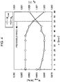
- a joint exists between plural linear grooves as illustrated in Fig. 1(b) .
- Relative positions of lines each of which passes through the central positions of the length (groove width) in the rolling direction of each of the linear grooves and is parallel to the groove forming direction (a center line P of a linear groove) at the joint were varied. It was found that, in the case that the positions of the center lines P are different (the center lines P are shifted), it is possible to realize a larger effect of improving iron loss than in the case that the positions are identical (the center lines P are collinear).
- a grain-oriented electrical steel sheet on which grooves have been formed is subjected to final annealing after an annealing separator is coated to the grooved steel sheet.
- This final annealing is performed for the purpose of the secondary recrystallization of the steel sheet and the formation of a forsterite coating film, and the forsterite coating film is also formed at the bottom of the groove.
- a forsterite coating film is densely formed, there is an improvement in iron loss due to an increase in the film tension. Therefore, linear grooves are formed such that, as illustrated in Fig.
- the present inventors conducted investigations regarding the most suitable method for forming a groove having such a discontinuous portion of center lines.
- An electroetching method was used as a groove formation method from the viewpoint of productivity and lamination factor.
- a method for forming a resist pattern as a result of comparison among a gravure printing method, an ink-jet printing method, and a resist removing method from the viewpoint of satisfactory shape of a groove, a resist removing method, with which the largest effect of improving iron loss was realized, was selected.
- a resist removing method with which the largest effect of improving iron loss was realized
- the spot diameter ⁇ of a laser beam is 1 ⁇ m or more.
- an increase in the spot diameter ⁇ of a laser beam decreases the energy density.
- the spot diameter ⁇ of a laser beam is 1 ⁇ m or more and 100 ⁇ m or less.
- the grain-oriented electrical steel sheet manufactured by using the manufacturing method according to the present invention can preferably be used as a material for an iron core for a transformer and the like and, in particular, a material for a wound iron core.
- the coated resist remaining on the surface was stripped in an alkaline solution, decarburization annealing was performed, an annealing separator containing mainly MgO was coated to the annealed steel strip, and the steel strip was wound into a coil. Thereafter, final annealing was performed. After flattening annealing was performed on the steel strip subjected to the final annealing, a tension coating was formed on the steel strip surface to obtain a final product steel strip. Steel sheets each having a length in the sheet transverse direction of 100 mm and a length in the rolling direction of 280 mm were taken from the obtained steel strip, and magnetic properties were evaluated.
- iron loss W 17/50 and magnetic flux density B 8 were used.
- W 17/50 denotes iron loss when alternating magnetization of 1.7 T and 50 Hz is performed in the rolling direction of the steel sheet
- B 8 denotes magnetic flux density when magnetization is performed in the rolling direction with a magnetizing force of 800 A/m.
- Iron loss W 17/50 and B 8 obtained by using each of the resist pattern forming methods are given in Table 1. It was clarified that a resist removing method provided the largest effect of improving iron loss. The reason for this is considered to be as follows. In the case of a resist removing method, since a melted portion as illustrated in Fig. 2 was formed when removing a coated resist from a steel sheet by using laser beams, the groove depth in such a portion after the electroetching was smaller than that of other portions. As a result, since there was a decrease in the sectional area of a flow channel of an atmosphere gas in the final annealing in the discontinuous portion 2 of center lines, there was a decrease in the flowability of the gas compared with the case of other methods.
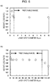
- resist patterns were formed by using two laser beams irradiated from two adjacent laser irradiation devices arranged in the strip transverse direction of the cold rolled steel strip. At this time, centers of the two adjacent laser beams having a laser spot diameter of ⁇ were shifted with each other in a direction perpendicular to the laser scanning direction. A coated resist was removed with various distances in the direction perpendicular to the laser scanning direction between the centers of the two laser beams (hereinafter, also referred to as "light path shifting distance d" (refer to Fig. 2 )).
- the laser spot diameter ⁇ was 100 ⁇ m, and the irradiation energy was 20 J/m.
- a length in the laser scanning direction of an overlapped portion 3 of portions irradiated with two adjacent laser beams (hereinafter, also referred to as "light path overlap length c" (refer to Fig. 2 )) was set to have a constant value of 10 mm.
- the laser spot diameter ⁇ is defined as the full-width at half maximum in the strength profile of a laser beam.
- the laser spot diameter ⁇ is set to be a spot diameter in a direction perpendicular to the laser scanning direction.
- a final product steel strip was obtained by performing the processes described above.
- Steel sheets each having a certain SST size that is, a length in the sheet transverse direction of 100 mm and a length in the rolling direction of 280 mm, were taken from the obtained steel strip, and W 17/50 and B 8 were evaluated.
- the results are given in Fig. 3 .
- the expression "light path shift ratio with respect to spot diameter ⁇ " in Fig. 3 denotes the ratio of the light path shift distance d to the spot diameter ⁇ .
- the appropriate range of the light path shift ratio is set to be 0.05 or more and 0.95 or less. That is, when the laser spot diameter is defined as ⁇ , the shift distance in a direction perpendicular to the laser scanning direction between the centers of two laser beams emitted from the two laser irradiation devices adjacent to each other in the sheet transverse direction is set to be ⁇ multiplied by 0.05 or more and 0.95 or less. It is more preferable that the light path distance ratio described above is 0.10 or more. In addition, it is more preferable that the light path shift ratio is 0.90 or less.
- the light path overlap length c was more than 50 mm, there was a decrease in the effect of improving iron loss. This is considered to be because, since there was an improvement in the flowability of the atmosphere gas due to an increase in light path overlap length c, it was difficult to form a dense forsterite coating film. Moreover, in the case that the light path overlap length c was more than 50 mm, it was also clarified that there was a deterioration in B 8 . This is considered to be because there was an increase in the volume of the groove due to an increase in light path overlap length c. From the results described above, it is preferable that the light path overlap length c is 50 mm or less.
- the light path overlap length c is set to be 0 mm or more. It is preferable that the light path overlap length c is 0.1 mm or more. In addition, it is more preferable that the light path overlap length c is 40 mm or less.
- a resist ink was coated across the whole surface of a cold rolled steel sheet for a grain-oriented electrical steel sheet whose weight had been measured, a linear resist pattern was formed by using one laser beam irradiated from one laser irradiation device, and electroetching was performed. At this time, electrolytic conditions were controlled so that the depth of the linear grooves formed by the electroetching had a constant value. After having stripped the coated resist remaining on the steel sheet subjected to electroetching, the weight of the steel sheet was measured, and a decrease in the weight of the steel sheet due to electroetching (weight loss) was calculated.
- a weight loss ratio As an index, appropriate conditions for the laser irradiation were investigated.
- the weight loss ratio approaches to 1.0, there is a decrease in the degree of groove shape defects such as groove breaks and white spots.
- Laser irradiation was performed (1) under the conditions of a spot diameter ⁇ of 100 ⁇ m and an irradiation energy of 0.5 J/m to 35 J/m and (2) under the conditions of an irradiation energy of 20 J/m and a spot diameter ⁇ of 0.5 ⁇ m to 120 ⁇ m.
- the irradiation energy was expressed in units of energy per unit scanning length ((laser power (W))/(scanning speed (m/sec))).
- the irradiation energy is 1 J/m or more and 30 J/m or less.
- the laser spot diameter ⁇ is 1 ⁇ m or more and 100 ⁇ m or less.
- the present invention is not limited to the constitutions disclosed in the embodiments, and the present invention may be performed by making various alterations within a range in accordance with the intent of the present invention.
- C is added to improve the microstructure of a hot rolled steel sheet
- the C content is more than 0.08 mass%
- secondary recrystallization occurs even in a steel material which does not contain C, there is no particular limitation on the lower limit of the C content.
- Si is an element effective for improving iron loss by increasing the electrical resistance of steel.
- the Si content is less than 2.0 mass%, it is not possible to sufficiently realize such an effect of improvement.
- the Si content is more than 8.0 mass%, there is a marked deterioration in workability and sheet passage, and there is a decrease in magnetic flux density. Therefore, it is preferable that the Si content is 2.0 mass% to 8.0 mass%.
- Mn is an element necessary to improve hot workability. However, in the case that the Mn content is less than 0.005 mass%, it is not possible to sufficiently realize such an effect. On the other hand, in the case that the Mn content is more than 1.0 mass%, there is a deterioration in magnetic flux density. Therefore, it is preferable that the Mn content is 0.005 mass% to 1.0 mass%.
- a slab for a grain-oriented electrical steel sheet has a chemical composition with which secondary recrystallization occurs.
- an inhibitor used to allow secondary recrystallization to occur, for example, it is sufficient that Al and N are appropriately added when an AIN-based inhibitor is used and that Mn and Se and/or S are appropriately added when a MnS-MnSe-based inhibitor is used. It is needless to say that both kinds of inhibitors may be used.
- the preferable content of each of Al, N, S, and Se is as follows.
- the present invention may be applied to a grain-oriented electrical steel sheet that does not use an inhibitor where the content of Al, N, S, or Se is limited.
- the content of each of Al, N, S, and Se be limited as follows.
- the optional constituents described below which are known to be effective for improving magnetic properties, may be appropriately added.
- Ni is an element effective for improving magnetic properties by improving the microstructure of a hot rolled steel sheet.
- the Ni content is less than 0.03 mass%, contribution to an improvement in magnetic properties is small.
- the Ni content is more than 1.50 mass%, since secondary recrystallization is unstable, there is a deterioration in magnetic properties. Therefore, it is preferable that the Ni content is 0.03 mass% to 1.50 mass%.
- Sn, Sb, Cu, P, Mo, and Cr are also elements that improve magnetic properties.
- the content of each of such elements is less than the corresponding lower limit described above, such an effect is insufficient.
- the content of each of such elements is more than the corresponding upper limit described above, since grain growth in secondary recrystallization is suppressed, there is a deterioration in magnetic properties. Therefore, it is preferable that the content of each of such elements is within the range described above.
- the remainder which is different from the constituents described above is Fe and incidental impurities.
- the contents of the basic constituents and the optional constituents other than C in a steel material (slab) are maintained.
- the contents of the inhibitor constituents in final annealing described below are at a level of incidental impurities.
- hot-rolled-sheet annealing is performed. Subsequently, cold rolling is performed once, optionally twice or more with intermediate annealing between periods that cold rolling is performed, to obtain a steel strip having the final thickness. Subsequently, after having performed decarburization annealing on the steel strip, coating of an annealing separator containing mainly MgO to the annealed steel strip, the steel strip is wound into a coil. Thereafter, a final annealing is performed for the purpose of the secondary recrystallization and the formation of a forsterite coating film. After having performed flattening annealing on the steel strip that had been subjected to final annealing, a magnesium phosphate-based tension coating is formed to obtain a product steel strip.
- linear grooves are formed on the surface of a grain-oriented electrical steel sheet (steel strip).
- groove dimensions includes not only a groove width and a groove depth but also a groove interval between grooves formed cyclically in the rolling direction of a grain-oriented electrical steel sheet (steel strip) and an angle formed by the longitudinal direction of the linear grooves and the sheet transverse direction.
- the groove width of the linear grooves corresponds to the width in the rolling direction of a portion from which a coated resist has been removed (portion which has been irradiated with a laser beam) in a resist pattern.
- the width of the portion from which a coated resist has been removed corresponds to the spot diameter of the laser beam used for removing the coated resist. Therefore, the groove width is about 1 ⁇ m to 100 ⁇ m.
- the effect of improving iron loss due to formation of grooves increases with an increase in the surface area of the side walls of the grooves, that is, an increase in the formed depth of the groove (groove depth). Therefore, it is preferable that a groove having a depth of 4% or more of the sheet thickness is formed.
- the upper limit of the groove depth is 25% of the sheet thickness.
- Linear groove forming interval 1.5 mm to 10 mm
- the linear groove forming interval is 1.5 mm to 10 mm.
- the expression "linear groove forming interval" denotes the distance in the rolling direction between linear grooves.
- the angle formed by the longitudinal direction of linear grooves and the sheet transverse direction is within a range of ⁇ 30°.
- laser spot diameter ⁇ denotes the full-width at half maximum in a strength profile obtained by using a slit method with a slit having a width of 30 ⁇ m.
- hot-rolled-sheet annealing was performed. Subsequently, cold rolling was performed twice with intermediate annealing between the periods that cold rolling was performed to obtain a cold rolled steel strip having a thickness of 0.23 mm.
- removal of the coated resist was performed by using two laser beams irradiated from two laser irradiation devices arranged in the strip transverse direction. At this time, as illustrated in Fig.
- laser beams were irradiated to form a resist pattern such that the groove interval in the rolling direction was 4 mm and an angle formed by the longitudinal direction of the grooves and the strip transverse direction was 10°.
- the amount of laser deflection was controlled so that overlapped portion of portions irradiated with the laser beams were arranged in the rolling direction.
- a resist pattern was formed the steel strip such that the light path shift ratio, the light path overlap length c, the irradiation energy, and the spot diameter ⁇ varied successively.
- the electroetching condition was set so that the groove depth was 20 ⁇ m (with exception of regions where a melted portion was formed).
- Samples having an RD length of 280 mm and a TD length of 100 mm were taken from the obtained steel strip such that each linear groove 1 contained one discontinuous portion of center lines, that is, such that each of the samples contains discontinuous portion of center lines. Further, W 17/50 and B 8 were determined by using a single sheet test (SST) method.
- SST single sheet test
- RD denotes the steel sheet rolling direction
- TD denotes the sheet transverse direction.
- samples were prepared by performing the same processes as described above with the exception that a resist pattern was formed by using a gravure printing method or an ink-jet printing method, and W 17/50 and B 8 were determined.
- the width of the grooves formed by using a gravure printing method or an ink-jet printing method was 50 ⁇ m.
Landscapes
- Chemical & Material Sciences (AREA)
- Engineering & Computer Science (AREA)
- Physics & Mathematics (AREA)
- Mechanical Engineering (AREA)
- Metallurgy (AREA)
- Organic Chemistry (AREA)
- Materials Engineering (AREA)
- Optics & Photonics (AREA)
- Plasma & Fusion (AREA)
- Electromagnetism (AREA)
- Thermal Sciences (AREA)
- Crystallography & Structural Chemistry (AREA)
- Manufacturing & Machinery (AREA)
- Power Engineering (AREA)
- Dispersion Chemistry (AREA)
- Manufacturing Of Steel Electrode Plates (AREA)
- Soft Magnetic Materials (AREA)
- Laser Beam Processing (AREA)
Applications Claiming Priority (2)
| Application Number | Priority Date | Filing Date | Title |
|---|---|---|---|
| JP2019140969A JP6939852B2 (ja) | 2019-07-31 | 2019-07-31 | 線状溝形成方法および方向性電磁鋼板の製造方法 |
| PCT/JP2020/026182 WO2021020027A1 (fr) | 2019-07-31 | 2020-07-03 | Procédé de formation d'une rainure linéaire et procédé de formation d'une tôle d'acier électrique à grains orientés |
Publications (2)
| Publication Number | Publication Date |
|---|---|
| EP4006182A1 true EP4006182A1 (fr) | 2022-06-01 |
| EP4006182A4 EP4006182A4 (fr) | 2022-09-14 |
Family
ID=74229975
Family Applications (1)
| Application Number | Title | Priority Date | Filing Date |
|---|---|---|---|
| EP20846730.8A Pending EP4006182A4 (fr) | 2019-07-31 | 2020-07-03 | Procédé de formation d'une rainure linéaire et procédé de formation d'une tôle d'acier électrique à grains orientés |
Country Status (8)
| Country | Link |
|---|---|
| US (1) | US12404563B2 (fr) |
| EP (1) | EP4006182A4 (fr) |
| JP (1) | JP6939852B2 (fr) |
| KR (1) | KR102676984B1 (fr) |
| CN (1) | CN114222828B (fr) |
| CA (1) | CA3143922C (fr) |
| MX (1) | MX2022001182A (fr) |
| WO (1) | WO2021020027A1 (fr) |
Families Citing this family (2)
| Publication number | Priority date | Publication date | Assignee | Title |
|---|---|---|---|---|
| EP4407643A4 (fr) * | 2021-12-14 | 2025-01-22 | JFE Steel Corporation | Procédé de fabrication de noyau de fer stratifié |
| CN120265810A (zh) * | 2022-11-22 | 2025-07-04 | 日本制铁株式会社 | 方向性电磁钢板 |
Family Cites Families (21)
| Publication number | Priority date | Publication date | Assignee | Title |
|---|---|---|---|---|
| JPS6286121A (ja) | 1985-10-14 | 1987-04-20 | Nippon Steel Corp | 鋼板への与歪装置 |
| JPH0622179B2 (ja) | 1986-10-09 | 1994-03-23 | 川崎製鉄株式会社 | 鉄損の低い変圧器用巻き鉄心 |
| JPH0622179A (ja) | 1992-06-30 | 1994-01-28 | Fuji Photo Optical Co Ltd | 小型雲台装置 |
| JP4189143B2 (ja) | 2001-10-22 | 2008-12-03 | 新日本製鐵株式会社 | 低鉄損一方向性電磁鋼板の製造方法 |
| TWI305548B (en) | 2005-05-09 | 2009-01-21 | Nippon Steel Corp | Low core loss grain-oriented electrical steel sheet and method for producing the same |
| MX2013002627A (es) | 2010-09-10 | 2013-04-24 | Jfe Steel Corp | Lamina de acero magnetica de grano orientado y proceso para producir la misma. |
| JP5953690B2 (ja) | 2011-09-28 | 2016-07-20 | Jfeスチール株式会社 | 方向性電磁鋼板およびその製造方法 |
| WO2015045693A1 (fr) | 2013-09-30 | 2015-04-02 | 株式会社シンク・ラボラトリー | Rouleau à motifs et son procédé de fabrication |
| US9620457B2 (en) * | 2013-11-26 | 2017-04-11 | Infineon Technologies Ag | Semiconductor device packaging |
| US9358635B2 (en) * | 2013-12-19 | 2016-06-07 | Siemens Energy, Inc. | Rastered laser melting of a curved surface path with uniform power density distribution |
| US10704113B2 (en) * | 2014-01-23 | 2020-07-07 | Jfe Steel Corporation | Grain oriented electrical steel sheet and production method therefor |
| KR101711853B1 (ko) * | 2014-12-24 | 2017-03-03 | 주식회사 포스코 | 강판 표면 홈 형성 방법 및 그 장치 |
| RU2686711C2 (ru) * | 2015-02-10 | 2019-04-30 | ДжФЕ СТИЛ КОРПОРЕЙШН | Способ производства листовой электротехнической стали с ориентированной структурой |
| CN107406935B (zh) | 2015-04-20 | 2019-03-12 | 新日铁住金株式会社 | 方向性电磁钢板 |
| WO2016171129A1 (fr) | 2015-04-20 | 2016-10-27 | 新日鐵住金株式会社 | Tôle d'acier électromagnétique orientée |
| JP6332185B2 (ja) * | 2015-07-22 | 2018-05-30 | Jfeスチール株式会社 | 鋼板表面に線状溝を形成する方法 |
| CA2987379C (fr) * | 2015-07-28 | 2019-10-29 | Jfe Steel Corporation | Procede de formation de rainure lineaire et dispositif de formation de rainures lineaires |
| ES2896904T3 (es) * | 2016-01-22 | 2022-02-28 | Tata Steel Nederland Tech Bv | Texturización por láser de flejes de acero |
| KR101892226B1 (ko) * | 2016-12-23 | 2018-08-27 | 주식회사 포스코 | 방향성 전기강판 및 그 자구미세화 방법 |
| WO2018175193A2 (fr) * | 2017-03-22 | 2018-09-27 | Corning Incorporated | Procédés de séparation d'une bande de verre |
| JP6977702B2 (ja) * | 2018-12-05 | 2021-12-08 | Jfeスチール株式会社 | 方向性電磁鋼板の鉄損改善方法およびその装置 |
-
2019
- 2019-07-31 JP JP2019140969A patent/JP6939852B2/ja active Active
-
2020
- 2020-07-03 CA CA3143922A patent/CA3143922C/fr active Active
- 2020-07-03 MX MX2022001182A patent/MX2022001182A/es unknown
- 2020-07-03 KR KR1020227003404A patent/KR102676984B1/ko active Active
- 2020-07-03 WO PCT/JP2020/026182 patent/WO2021020027A1/fr not_active Ceased
- 2020-07-03 CN CN202080055073.4A patent/CN114222828B/zh active Active
- 2020-07-03 EP EP20846730.8A patent/EP4006182A4/fr active Pending
- 2020-07-03 US US17/630,853 patent/US12404563B2/en active Active
Also Published As
| Publication number | Publication date |
|---|---|
| KR20220028074A (ko) | 2022-03-08 |
| US20220267872A1 (en) | 2022-08-25 |
| MX2022001182A (es) | 2022-02-22 |
| JP2021025061A (ja) | 2021-02-22 |
| WO2021020027A1 (fr) | 2021-02-04 |
| EP4006182A4 (fr) | 2022-09-14 |
| CN114222828A (zh) | 2022-03-22 |
| CA3143922C (fr) | 2023-12-19 |
| US12404563B2 (en) | 2025-09-02 |
| KR102676984B1 (ko) | 2024-06-19 |
| JP6939852B2 (ja) | 2021-09-22 |
| CN114222828B (zh) | 2024-03-15 |
| CA3143922A1 (fr) | 2021-02-04 |
Similar Documents
| Publication | Publication Date | Title |
|---|---|---|
| JP6157360B2 (ja) | 方向性電磁鋼板およびその製造方法 | |
| KR101593346B1 (ko) | 방향성 전기 강판 및 그 제조 방법 | |
| JP5742294B2 (ja) | 方向性電磁鋼板の製造方法 | |
| EP2602348A1 (fr) | Tôle d'acier magnétique à grains orientés | |
| EP2623633A1 (fr) | Tôle d'acier électromagnétique orientée | |
| JP6825681B2 (ja) | 方向性電磁鋼板およびその製造方法 | |
| WO2015111434A1 (fr) | Plaque d'acier magnétique directionnel et son procédé de production | |
| JP5953690B2 (ja) | 方向性電磁鋼板およびその製造方法 | |
| EP4006182A1 (fr) | Procédé de formation d'une rainure linéaire et procédé de formation d'une tôle d'acier électrique à grains orientés | |
| CN103069034A (zh) | 方向性电磁钢板及其制造方法 | |
| KR102764566B1 (ko) | 방향성 전기 강판 | |
| EP4006181A1 (fr) | Tôle d'acier électrique à grains orientés | |
| JP7010321B2 (ja) | 方向性電磁鋼板およびその製造方法 | |
| CN115335546A (zh) | 取向性电磁钢板及其制造方法 | |
| EP4675653A1 (fr) | Noyau de fer pour transformateur et transformateur |
Legal Events
| Date | Code | Title | Description |
|---|---|---|---|
| STAA | Information on the status of an ep patent application or granted ep patent |
Free format text: STATUS: THE INTERNATIONAL PUBLICATION HAS BEEN MADE |
|
| PUAI | Public reference made under article 153(3) epc to a published international application that has entered the european phase |
Free format text: ORIGINAL CODE: 0009012 |
|
| STAA | Information on the status of an ep patent application or granted ep patent |
Free format text: STATUS: REQUEST FOR EXAMINATION WAS MADE |
|
| 17P | Request for examination filed |
Effective date: 20220111 |
|
| AK | Designated contracting states |
Kind code of ref document: A1 Designated state(s): AL AT BE BG CH CY CZ DE DK EE ES FI FR GB GR HR HU IE IS IT LI LT LU LV MC MK MT NL NO PL PT RO RS SE SI SK SM TR |
|
| A4 | Supplementary search report drawn up and despatched |
Effective date: 20220811 |
|
| RIC1 | Information provided on ipc code assigned before grant |
Ipc: C22C 38/60 20060101ALN20220805BHEP Ipc: C22C 38/34 20060101ALN20220805BHEP Ipc: C22C 38/18 20060101ALN20220805BHEP Ipc: C22C 38/16 20060101ALN20220805BHEP Ipc: C22C 38/12 20060101ALN20220805BHEP Ipc: C22C 38/02 20060101ALN20220805BHEP Ipc: C22C 38/00 20060101ALN20220805BHEP Ipc: C21D 9/46 20060101ALI20220805BHEP Ipc: B23K 103/04 20060101ALI20220805BHEP Ipc: B23K 101/16 20060101ALI20220805BHEP Ipc: B23K 26/40 20140101ALI20220805BHEP Ipc: B23K 26/362 20140101ALI20220805BHEP Ipc: B23K 26/08 20140101ALI20220805BHEP Ipc: B23K 26/067 20060101ALI20220805BHEP Ipc: B23K 26/06 20140101ALI20220805BHEP Ipc: H01F 1/147 20060101ALI20220805BHEP Ipc: B23K 26/361 20140101ALI20220805BHEP Ipc: C21D 8/12 20060101AFI20220805BHEP |
|
| DAV | Request for validation of the european patent (deleted) | ||
| DAX | Request for extension of the european patent (deleted) |