EP4006256B1 - Firstmontage- und belüftungssystem - Google Patents
Firstmontage- und belüftungssystem Download PDFInfo
- Publication number
- EP4006256B1 EP4006256B1 EP21211111.6A EP21211111A EP4006256B1 EP 4006256 B1 EP4006256 B1 EP 4006256B1 EP 21211111 A EP21211111 A EP 21211111A EP 4006256 B1 EP4006256 B1 EP 4006256B1
- Authority
- EP
- European Patent Office
- Prior art keywords
- ridge
- slates
- natural stone
- ventilation system
- mounting
- Prior art date
- Legal status (The legal status is an assumption and is not a legal conclusion. Google has not performed a legal analysis and makes no representation as to the accuracy of the status listed.)
- Active
Links
Images


Classifications
-
- E—FIXED CONSTRUCTIONS
- E04—BUILDING
- E04D—ROOF COVERINGS; SKY-LIGHTS; GUTTERS; ROOF-WORKING TOOLS
- E04D13/00—Special arrangements or devices in connection with roof coverings; Protection against birds; Roof drainage ; Sky-lights
- E04D13/17—Ventilation of roof coverings not otherwise provided for
- E04D13/174—Ventilation of roof coverings not otherwise provided for on the ridge of the roof
-
- E—FIXED CONSTRUCTIONS
- E04—BUILDING
- E04D—ROOF COVERINGS; SKY-LIGHTS; GUTTERS; ROOF-WORKING TOOLS
- E04D1/00—Roof covering by making use of tiles, slates, shingles, or other small roofing elements
- E04D1/12—Roofing elements shaped as plain tiles or shingles, i.e. with flat outer surface
- E04D1/16—Roofing elements shaped as plain tiles or shingles, i.e. with flat outer surface of ceramics, glass or concrete, with or without reinforcement
-
- E—FIXED CONSTRUCTIONS
- E04—BUILDING
- E04D—ROOF COVERINGS; SKY-LIGHTS; GUTTERS; ROOF-WORKING TOOLS
- E04D1/00—Roof covering by making use of tiles, slates, shingles, or other small roofing elements
- E04D1/30—Special roof-covering elements, e.g. ridge tiles, gutter tiles, gable tiles, ventilation tiles
- E04D2001/304—Special roof-covering elements, e.g. ridge tiles, gutter tiles, gable tiles, ventilation tiles at roof intersections, e.g. valley tiles, ridge tiles
- E04D2001/305—Ridge or hip tiles
Definitions
- the present invention provides a natural stone ridge configured for mechanical fixation to an apex of a roof structure.
- the present invention also provides a natural stone ridge configured to provide ventilation to a roof space of a roof structure.
- Roofs are predominantly triangular shaped timber structures with resemblance to a tent or pyramid that sit on the top of a building so as to direct rainwater and snow water away from the building. These structures are covered with a variety of resilient weather proof roof coverings in various forms such as stone, slates, clay and concrete so as to remain waterproof.
- a roof When installed, a roof has an arrangement of flat sides that lean together.
- a roof structure typically, there are two different aspects of a roof structures.
- a first aspect of a roof structure is for example a tent shaped roof as shown in Figure 1 which has two sides that lean together at the upper horizontal edge called a ridge.
- a second aspect of a roof structure is a pyramid shaped roof as shown in Figure 2 which has four sides that lean together at the angular side edges called hips.
- Stone has been used in roofing for many hundreds of years, the stone slates are usually formed from sedimentary shale that can be split and then shaped into relatively flat layers.
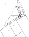
- Figures 3 and 4 illustrate roofing formed from stone slates (C) laid onto timber supports of a roof structure (D) to form a resilient roof covering.
- Ridge tiles (E) are placed at the very top of the roof structure so as to cover the intersection between the different flat plains of the roof.
- the ridge tiles can be made in several different angles, sizes and colours.
- Figures 3 and 4 illustrate the use of ridge tiles on two slightly different aspects of a roof.
- Figure 3 shows a tent shaped roof in which the upper point at which two opposite sides converge is called the apex (marked with "X" in Figure 1 ).
- Figure 3 illustrates a traditional method of cement bedding a ridge.
- the ridge tile (E) is an angular piece of stone (having a 90-degree cross-section, forming an upside down 'V') and is set in position over the junction between the two opposite sides at the apex.
- Cement (F) is used to secure the ridge tile in position, thus forming a weatherproof seal and completing the roof installation.
- the pyramid shaped roof (as shown in Figure 2 ) is formed when two adjacent sides of a roof meet externally and as a result the junction is a compound angle, and the plane of the junction is shallower.
- These side ridge junctions are known as a hip ridge and hip ridge tiles and are used to seal this junction typically forms an angle of around 120 degrees.
- the traditional aspect of the installed stone roof has an extremely desirable aesthetic and, in many areas where these types of roofs are prevalent, the use of traditional stone is required under local authority planning regulations. Angular ridge tiles are however typically hewed from a solid piece of stone. This can be extremely laborious and expensive.
- roof ventilation systems exist that utilise metal brackets that are mechanically fixed to the roof frame. These brackets are used to fix and locate a ridge runner batten (i.e. a standard length of roofing timber running along the apex of the roof line and directly below the ridge) to which the ridge tiles are mechanically fixed.
- a ridge runner batten i.e. a standard length of roofing timber running along the apex of the roof line and directly below the ridge
- preformed plastic joining brackets that are placed onto the end of each tile prior to installation. These joining brackets enable each ridge tile to abut the previous ridge tile whilst at the same time sealing the join and holding the tiles in place.
- FIG. 4 illustrates the passage of moist air that is drawn through a modern, vented ridge as described above.
- ridge ventilation systems for use with conventional ridge tiles, for example with concrete or clay ridge tiles, which allow a small gap around the edge of the ridge tiles to enable free movement of air below the ridge tile that carries away moisture.
- United States patent application number US 2012/0096782 discloses a ridge ventilation system that includes a plurality of ridge vent sections configured to be arranged end-to-end along the ridge of a roof covering a vent slot.
- Each ridge vent section has an elongated longitudinally flexible top panel with a central portion. Edge portions terminates at extreme edges of the top panel and ventilation grids extend beneath and along the edge portions spaced from extreme edges thereof. The space between the extreme edges of the top panel and the ventilation grids forms or defines an overhang configured to receive edges of shingles in a course of shingles installed next to the vent section and to inhibit the edges of the shingles from rising up.
- WO-A-97/21007 discloses a roofing ridge (or hip) installation which includes a roof under structure with a pair of outwardly sloping walls which form an inverted V-shaped ridge.
- a support panel is mounted on each of the walls with the lower end of each support panel optionally terminating in an upwardly facing channel. Tiles such as slates are mounted in each channel.
- a pressure applying assembly forces the base end of the panels inwards and a cap spans across and covers the upper ends of the panels and assembly.
- US 2020/048909 discloses another ridge system with a pair of stone slates overlaying a flexible liner.
- a ridge mounting and ventilation system comprising: at least a pair of flat natural stone slates bonded one to another along their mitred edges to define a ridge, characterised in that the ridge overlays a rigid waterproof backing formed by a glass-reinforced polyester (GRP) liner; and at least one spacer is located at or adjacent each lower edge of the slates to space the lower edge from a surface on which the slates rest to define an opening for ventilating the apex of an installed roof structure.
- GRP glass-reinforced polyester
- Spacers may be defined by relatively raised and lowered portions formed along lower edges of the flat natural stone slates or they may comprise separate pieces as described below.
- the invention solves problems associated with ventilating a roof space whilst maintaining mechanical integrity and strength of the ridge mounting and provides an aesthetic and natural appearance by ensuring that the ridge mounting and ventilation system comprises at least one pair of flat natural stone slates.
- Each pair of flat natural stone slates is configured to abut one another along their edges to form a weatherproof ridge, in which glass reinforced polyester (GRP) is adhered or mechanically fixed to inners faces of each of the natural stone slates thereby forming a weatherproof connection between.
- GRP glass reinforced polyester
- the present invention has a rigid waterproof backing which provides a mechanical substrate that is strong.
- polyester resin used to fabricate the glass reinforced polyester may be placed in the gap between the pair of flat natural stone slates and extends through the thickness of each natural stone across the entirety of the joint between them.
- an additional binding material may be used to join the pair of natural stone slates at their mitred faces.
- the ridge formed between the pair(s) of natural stone slates may be formed to include any suitable angle, depending on the particular requirements of the roof structure.
- the ridge formed between the pair(s) of natural stone slates preferably has an angle of around 90°, for a tent-shaped roof structure, and an angle of about 120° degrees, for a pyramid-shaped roof structure.
- the glass-reinforced polyester (GRP) preferably provides a continuous layer extending between the at least one pair of natural stone slates.
- the glass-reinforced polyester (GRP) may include a preformed liner made from polymers or similar materials to form a permanent joint extending between the pair of natural stone slates.
- the glass-reinforced polyester (GRP) or preformed liner made from polymers or similar preferably provides a continuous layer extending along the inner surfaces of each of the natural stone slates within the pair of slates and extending between the pair of natural stone slates to form the permanent joint.
- the at least one pair of slates preferably further comprises at least one securement means configured to receive and adhere to the glass reinforced polyester or preformed liner made from polymers or similar to form a mechanical joint thereto.
- The, or each, natural stone or stone slate may comprise a plurality of securement means in any suitable configuration in order to provide a plurality of mechanical joins between the slate and the layer of glass reinforced polyester (GRP) or preformed liner made from polymers or similar
- GRP glass reinforced polyester
- the at least one securement means may comprise any feature that is suitable to provide a mechanical join between the slate and the glass reinforced polyester (GRP) or preformed liner made from polymers or similar.
- the at least one securement means comprises a recess extending from the inner surface towards the outer surface of natural stone slate.
- the recess may have any suitable shape and/or dimensions.
- the or, each recess is substantially V-shaped, for example butterfly-shaped.
- each flat natural stone slate of each pair of flat natural stone slates comprises a first end configured to abut a first end of the other corresponding flat natural stone slate within the pair, and a second opposed free end.
- the system preferably further comprises at least one spacer configured to be located at or adjacent the second free end thereof.
- the at least one spacer is configured to abut an underlying apex of an installed roof structure and to support the adjacent flat natural stone slate thereon at a predetermined location spaced apart from the underlying apex.
- the spacer(s) is configured to provide spacing between the slate and the underlying roof structure to enable air to pass therebetween providing ventilation to the roof structure, especially the apex of the roof structure.
- the spacer(s) may have any suitable shape and/or dimensions to provide at least one passageway for air, in which the passageway extends from the cavity provided within the roof structure (preferably at or adjacent the apex) and an external air environment.
- the at least one spacer has a first end configured in use to located between the glass reinforced polyester and the corresponding surface of the natural stone slate, and a second opposed free end configured to contact and abut an underlying apex of an installed roof structure.
- the first free end may be configured to form a mechanical join with the corresponding surface of the natural stone slate.
- the first free end may be curved or hooked in shape to engage with an opening or recess provided in the natural stone slate.
- the first free end may be adhered to the corresponding surface of the natural stone slate by a layer of glass reinforced polyester or preformed liner made from polymers or similar
- the at least one spacer defines a mounting edge extending from the first end towards the second free end thereof, in which the mounting edge is configured to abut and support a surface of the natural stone slate.
- the second free end of the at least one spacer preferably comprises an outwardly extending portion extending in a direction away from the mounting edge.
- the outwardly extending portion is preformed and formed from polymer materials or in a curved or hooked portion.
- the at least one spacer may be S-shaped or Z-shaped, preferably Z-shaped.
- the at least one spacer is formed from metal, for example from aluminium.
- the system preferably further comprises at least one first attachment member configured to extend from a permanent joint formed by glass reinforced polyester (GRP) or preformed liner made from polymers or similar extending between adjacent natural stone slabs to engage an adjacent first surface of a ridge runner batten.
- the at least one first attachment member is preferably a threaded attachment member configured to engage a ridge runner batten, for example by a threaded connector.
- the system may further comprise a sealable fixing locater prepositioned at a predetermined location on the permanent joint formed by GRP or preformed in polymers extending between adjacent natural stone slabs.
- the sealable fixing locater is preferably configured to receive a first attachment member extending therethrough.
- the system further comprises at least one corrosion resistant mounting bracket configured to be mountable on an apex of a roof frame, and configured to receive, engage and/or support a second surface of a ridge runner batten thereon.
- the corrosion resistant mounting bracket is preferably composed of corrosion resistant material, such as for example polymer(s).
- the system may comprise at least one first attachment member configured to extend from a permanent joint formed by GRP or preformed liner made from polymers or similar extending between adjacent natural stone slabs to engage an adjacent first surface of a ridge runner batten.
- the system may further comprise at least one corrosion resistant mounting bracket configured to receive, engage and/or support a second opposed surface of a ridge runner batten.
- the at least one first attachment member may be vertically aligned with at least one corrosion resistant mounting bracket.
- the corrosion resistant mounting bracket(s) may comprise a first end providing a first channel shaped and dimensioned to receive the apex and a second opposed end providing a second channel shaped and dimensioned to receive the batten.
- the first and second channels may have any suitable shape and dimensions.
- the corrosion resistant mounting bracket(s) comprises a first end providing a V-shaped channel with wings angled and configured to be support so as to accommodate the roof pitch variation when on the apex, and an opposed second end providing a U-shaped channel for receiving a ridge runner batten thereon.
- the system may further comprise at least one second attachment members located adjacent a first channel and configured for engaging the apex of a roof structure.
- the second attachment members may for example be located at or adjacent and extending outwardly from the first channel.
- the second attachment feature may further comprise a threaded member for threaded engagement with a corresponding surface of the apex of the roof structure.
- the ridge formed by a pair of natural stone slates, preferably comprises a front surface, and opposed rear surface, extending between the upper and lower surfaces of the slates.
- the layer of GRP or preformed liner made from polymers or similar extends beyond at least one of the front and/or rear surface.
- the extended layer of GRP or similar (beyond the front and/or rear surface of the ridge) is configured to prevent water ingress between adjacent ridges (i.e. between adjacent pairs of natural stone slates).
- the extended layer of GRP or a material with similar properties provides one or more ribs extending substantially perpendicular to the longitudinal axis of the ridge.
- the one or more ribs prevent tracking of water underneath the ridges.
- one or more sealable fixing locator may be located on the extended layer of GRP or preformed liner made from polymers or similar
- the system may further comprise at least one alignment member located at or adjacent a front and/or rear surface of the ridge.
- the at least one alignment member may be configured to engage and secure to an extended layer of GRP or a material with similar properties of an adjacent ridge, thereby enabling a plurality of ridges formed from a plurality of pairs of natural stone slates to be aligned and secured together to form a water tight ridge along a roof structure.
- a natural stone ridge configured for mechanical fixation to an apex of a roof structure.
- the natural stone ridge comprises at least one pair of natural stone slabs adhered to layer of glass reinforced polyester (GRP) or preformed liner made from polymers or similar extending therebetween.
- GRP glass reinforced polyester
- a natural stone ridge configured to provide ventilation to a roof space of a roof structure.
- the natural stone ridge comprises at least one natural stone component comprising an inner surface and an opposed outer surface, at least one spacer configured to be secured to an inner surface of the at least one natural stone component, and a layer of GRP or a material with similar properties adhered to the inner surface of the natural stone component.
- the natural stone ridge may further comprise at least one spacer configured to support flat natural stone slate positioned thereon at a predetermined location spaced apart from an underlying apex of a roof structure.
- the invention may be supplied as a kit for forming a natural stone ridge configured for mechanical fixation and/or ventilation, the kit comprising:
- the kit may comprise a plurality of spacers covering a range of different dimensions and/or shapes such that the user can select a suitable spacer for a given roof structure.
- a method for producing a ridge mounting and ventilation system comprising the steps of:
- the present invention provides a system for providing a ridge for a roof structure which is able to comply with planning regulations (so as to be formed from natural stone) as well as effectively reducing moisture levels within a roof space.
- the system of the present invention is able to provide a ridge which can be mechanically secured to a roof structure whilst also providing ventilation to an underlying roof space.
- the system of the present invention is also flexible enough to enable a ridge to be formed from natural stone slabs having the required angle for a particular apex.
- the system of the present invention has also been found to have an increased life span due to using components which are corrosion resistant.
- the roof structure 1 is a tent shaped roof which has two sides 2a, 2b that lean together at the upper horizontal edge called a ridge.
- the ridge formed between the pair(s) of natural stone slates may form any suitable angle depending on the particular requirements for the roof structure.
- the ridge formed between the pair(s) of natural stone slates preferably has an angle of about 90 degrees for a tent-shaped structure and an angle of about 120 degrees for a pyramid-shaped structure.
- the ridge mounting and ventilation system 10 of the present invention utilises a pair of flat natural stones 12a, 12b in conjunction with a layer of glass-reinforced polyester (GRP) 13 and a mounting system 18 to form a high performance ridge that faithfully emulates a traditionally hewed stone ridge and which can be mechanically fixed to provide ventilation to the apex of an installed roof structure.
- GRP glass-reinforced polyester
- the ridge mounting and ventilation system 10 comprises a plurality of pairs of flat natural stones or stone slates 12a, 12b aligned with and positioned adjacent each other along the ridge of the apex of the roof structure.
- Each pair of flat natural stone slates 12a, 12b is configured to abut one another along one edge thereof to form a ridge.
- Each natural stone slate has an outer surface 14a, 14b and an opposed inner surface 16a, 16b.
- a layer of glass-reinforced polyester (GRP) or a preformed liner made from polymer 13 or a similar waterproof material, is adhered or mechanically fixed to the inner surface 16a, 16b of the natural stone slates 12a, 12b.
- GRP glass-reinforced polyester
- the glass-reinforced polyester (GRP or similar) 13 provides a continuous waterproof layer extending between each pair of natural stone slates 12a, 12b.
- the glass-reinforced polyester (GRP) 13 forms a permanent joint extending between each pair of natural stone slates.
- Each slate 12a, 12b within each pair of slates further comprises a securement means 20a, 20b configured to receive and adhere to the glass reinforced polyester to form a mechanical join thereto. It is to be understood that although in the illustrated embodiment, each slate provides a single securement means 20a, 20b, each slate may comprise a plurality of securement means in any suitable configuration in order to provide a plurality of mechanical joins between the slate and the layer of glass reinforced polyester (GRP)
- the securement means 20a, 20b is provided as a butterfly-shaped recess located adjacent the centre of the slate 12a, 12b.
- the GRP is applied to the slate and extends into the recess to form a mechanical join of the securement means 20a, 20b.
- Each flat natural stone slate 12a, 12b of each pair of flat natural stone slates comprises a first end 22a configured to abut a first end 22b of the other corresponding flat natural stone slate within the pair, and a second opposed free end 24a, 24b.
- the system 10 further comprises a spacer 26a, 26b configured to be located at or adjacent the second free end 24a, 24b of the slate 12a, 12b.
- the spacers 26a, 26b are configured to abut an underlying apex 1 of an installed roof structure and to support the adjacent flat natural stone slate 12a, 12b thereon at a predetermined location spaced apart from the underlying apex.
- the spacers are configured to provide spacing between the slate and the underlying roof structure to enable air to pass therebetween providing ventilation to the roof structure, especially the apex of the roof structure.
- the spacer(s) may have any suitable shape and/or dimensions to provide at least one passageway for air, in which the passageway extends from the cavity provided within the roof structure (preferably at or adjacent the apex) and an external air environment.
- the spacer has a first free end 28a, 28b located between the glass reinforced polyester or similar 13, and the corresponding surface of the natural stone slate 12a, 12b, and a second opposed free end 30a, 30b configured to contact and abut an underlying apex 1 of an installed roof structure.
- the first free end 28a, 28b is be adhered to the corresponding surface of the natural stone slate 12a, 12b by a layer of glass reinforced polyester 13.
- the second free end 30a, 30b of the spacer 26a, 26b comprises an outwardly extending hooked or folded portion.
- the system preferably further comprises a first attachment member 32 configured to extend from the permanent joint 33 formed by glass reinforced polyester (GRP) 13 extending between adjacent natural stone slabs 12a, 12b to engage an adjacent first surface 34 of a ridge runner batten 36.
- the first attachment member in the illustrated embodiment is a threaded attachment member configured to engage a ridge runner batten 36, for example by way of a threaded connector.
- the system further comprises a sealable fixing locater 38 prepositioned at a predetermined location on the permanent joint 33 formed by GRP 13 extending between adjacent natural stone slabs.
- the sealable fixing locater 38 is configured to receive a first attachment member extending therethrough.
- the system further comprises a corrosion resistant mounting bracket 18 configured to be mountable on an apex 1 of a roof frame, and configured to receive, engage and/or support a second surface of a ridge runner batten 36 thereon.
- the corrosion resistant mounting bracket 18 is composed of corrosion resistant material, such as for example polymer(s).
- the corrosion resistant mounting bracket 18 comprises a first end 40 providing a first channel 42 shaped and dimensioned to receive the apex 1 and a second opposed end 44 providing a second channel 46 shaped and dimensioned to receive the batten 36.
- the first and second channels 42, 46 may have any suitable shape and dimensions.
- the corrosion resistant mounting bracket(s) 18 comprises a first end 40 providing a V-shaped channel 42 configured to be support on the apex 1, and an opposed second end 44 providing a U-shaped channel 46 for receiving a ridge runner batten 36 thereon.
- the mounting bracket 18 further comprises second attachment members 48 located adjacent a first channel 42 and configured for engaging the apex 1 of a roof structure.
- the ridge is formed by a plurality of aligned pairs of natural stone slates 12a, 12b, 112a, 112b.
- Each pair of slates 12a, 12b, 112a, 112b comprises a front surface 50, 150 and opposed rear surface 52, 152 extending between the upper and lower surfaces of the slates 12a, 12b, 112a, 112b.
- the layer of GRP or similar 13 extends beyond at least one of the front and/or rear surface 50, 150, 52, 152.
- the extended layer of GRP or similar (beyond the front and/or rear surface of the ridge) is configured to prevent water ingress between adjacent ridges (i.e. between adjacent pairs of natural stone slates).
- the extended layer of GRP or similar 13 provides a pair of spaced apart ribs 54a, 54b extending substantially perpendicular to the longitudinal axis of the ridge.
- the one or more ribs prevent tracking of water underneath the ridges.
- the sealable fixing locator 38 is located on the extended layer of GRP.
- the system further comprises alignment members 60 located at or adjacent a front and/or rear surface 50, 150, 52, 152 of the ridge.
- the alignment members 60 are Z-shaped and configured to engage and secure to an extended layer of GRP or similar 13 of an adjacent ridge, thereby enabling a plurality of ridges formed from a plurality of pairs of natural stone slates to be aligned and secured together to form a water tight ridge along a roof structure.
- a flat piece of natural stone is split in a traditional manner to offer a desired natural riven external surface.
- the stone is then accurately sized into two rectangular mirrored pieces that have a mitred cut along one length and are brought together to form an angular joined piece of stone, also referred to herein as a ridge.
- the angle of the cut can be varied depending on the requirements of the roof on which the ridge would be installed. Common angles include 90 degrees, 105 degrees and 120 degrees, although the angle can be varied as required.
- the two stone slates are inverted and placed into a specific jig and primed so that they can be adhered together using glass reinforced polyester.
- Spacers 26a, 26b are positioned adjacent the second free ends of the slate.
- Glass reinforced polyester is extremely strong, resilient and permanently waterproof and can be readily formed into any shape whereby it will set permanently when cured.
- the GRP is wet laid onto the stone and into the extended sections of the jog to form a permanent join between the slates. A critical bond is formed between the slate, the GRP layer and the GRP retained within the securement means 20a, 20b. By allowing the GRP to flow into the securement means, the GRP is locked onto the slate when cured.
- the mounting bracket 18 is positioned on the apex 1 such that the apex 1 is received within the first channel 42.
- Second attachment members 48 secured the mounting bracket 18 in position relative to the apex.
- the batten 36 is inserted into the second channel 46 of the mounting bracket 18.
- the ridge formed by the pair of slates 12a, 12b and the GRP 13, is positioned onto the roof structure.
- the GRP 13 extends beyond the rear 52 of the ridge (see Figure 6 ).
- a first attachment member 32 is inserted through the sealable fixing locater 38 to engage the batten 36, for example by way of a threaded connector.
- a second ridge formed from a pair of slates 112a, 112b is positioned adjacent to the first pair of slates 12a, 12b along the apex of the roof structure. Alignment members 60 ensure the pairs of slates 12a, 12b, 112a, 112b are accurately aligned with each other.
- spacers 26a, 26b provide an air passageway extending from the roof space of the roof structure, under the slates 12a, 12b of the ridge and into the external environment, thereby providing adequate ventilation of the roof space.
- the present invention provides a natural stone ridge configured for mechanical fixation to an apex of a roof structure and as such satisfies planning regulations. Furthermore, the system of the present invention is corrosion resistance and therefore has an enhanced life span compared to conventional systems.
- a keystone insert or bead may be bonded to the pair of flat natural stone slates, for example along their join, to add mechanical strength and resist relative bending of the pair of flat natural stone slates.
Landscapes
- Engineering & Computer Science (AREA)
- Architecture (AREA)
- Civil Engineering (AREA)
- Structural Engineering (AREA)
- Chemical & Material Sciences (AREA)
- Ceramic Engineering (AREA)
- Roof Covering Using Slabs Or Stiff Sheets (AREA)
Claims (15)
- Firstmontage- und -belüftungssystem, umfassend: mindestens ein Paar von flachen Natursteinschieferplatten (12a, 12b), die entlang ihrer Gehrungskanten (22a, 22b) aneinander gebondet sind, um einen First zu definieren, dadurch gekennzeichnet, dass der First auf einem steifen wasserfesten Träger aufliegt, der von einer Auskleidung (13) aus glasfaserverstärktem Polyester (GRP) gebildet wird; und mindestens ein Abstandshalter (26a, 26b) an oder angrenzend an jeder unteren Kante der Schieferplatten (12a, 12b) angeordnet ist, um die untere Kante von einer Oberfläche zu beabstanden, auf der die Schieferplatten (12a, 12b) ruhen, um eine Öffnung zum Belüften des Scheitelpunkts einer installierten Dachstruktur zu definieren.
- Firstmontage- und -belüftungssystem nach Anspruch 1, dadurch gekennzeichnet, dass die Natursteinschieferplatten (12a, 12b) eine Außenfläche (14a, 14b) und eine entgegengesetzte Innenfläche (16a, 16b) aufweisen und die Auskleidung (13) aus glasfaserverstärktem Polyester an der Innenfläche (16a, 16b) jeder der Natursteinschieferplatten (12a, 12b) haftet.
- Firstmontage- und -belüftungssystem nach Anspruch 2, dadurch gekennzeichnet, dass mindestens ein Sicherungsmittel (20a, 20b) in Natursteinschieferplatten (12a, 12b) ausgebildet ist oder an diese gebondet ist und dazu konfiguriert ist, die Auskleidung (13) aus glasfaserverstärktem Polyester aufzunehmen und an dieser zu haften.
- Firstmontage- und -belüftungssystem nach Anspruch 3, dadurch gekennzeichnet, dass das mindestens eine Sicherungsmittel (20a, 20b) eine Aussparung umfasst, die sich entlang der Innenfläche der Natursteinschieferplatten (12a, 12b) erstreckt.
- Firstmontage- und -belüftungssystem nach einem vorhergehenden Anspruch, dadurch gekennzeichnet, dass ein erstes Anbringungselement (32) dazu konfiguriert ist, sich von der Auskleidung (13) aus glasfaserverstärktem Polyester zu erstrecken, um mit einer Firstläuferlatte (36) in Eingriff zu kommen.
- Firstmontage- und -belüftungssystem nach Anspruch 5, dadurch gekennzeichnet, dass ein abdichtbarer Fixierungslokator (38) an einer vorbestimmten Stelle auf der Auskleidung (13) aus glasfaserverstärktem Polyester (GRP) vorpositioniert wird.
- Firstmontage- und -belüftungssystem nach Anspruch 5 oder 6, dadurch gekennzeichnet, dass eine korrosionsbeständige Montageklammer (18) dazu konfiguriert ist, auf einem Scheitelpunkt (1) eines Dachrahmens montierbar ist, und dazu konfiguriert ist, die Firstläuferlatte (36) aufzunehmen und zu stützen.
- Firstmontage- und -belüftungssystem nach Anspruch 7, dadurch gekennzeichnet, dass jeder der mindestens zwei Abstandshalter (26a, 26b) ein erstes freies Ende (28a, 28b), das zwischen der Auskleidung (13) aus glasfaserverstärktem Polyester und den entsprechenden Flächen der Natursteinschieferplatten (12a, 12b) angeordnet ist, und ein zweites entgegengesetztes freies Ende (30a, 30b), das dazu konfiguriert ist, ein darunter liegendes Dachelement, wie einen Ziegel oder eine Schieferplatte oder eine Steinplatte, zu berühren und darauf zu ruhen.
- Firstmontage- und -belüftungssystem nach Anspruch 8, dadurch gekennzeichnet, dass das mindestens eine Abstandselement (26a, 26b) eine Montagekante definiert, die sich von dem ersten freien Ende (28a, 28b) zu dem zweiten entgegengesetzten freien Ende (30a, 30b) hin erstreckt, wobei die Montagekante an einen unteren Teil (24a, 24b) der Natursteinschieferplatten (12a, 12b) anstößt und diesen stützt, und wobei das zweite entgegengesetzte freie Ende (30a, 30b) des mindestens einen Abstandshalters (26a, 26b) einen sich nach außen erstreckenden Teil umfasst, der sich in einer Richtung von der Montagekante weg erstreckt.
- Firstmontage- und -belüftungssystem nach Anspruch 9, dadurch gekennzeichnet, dass der sich nach außen erstreckende Teil des mindestens einen Abstandshalters (26a, 26b) einen gewölbten Teil umfasst.
- Firstmontage- und -belüftungssystem nach einem vorhergehenden Anspruch, dadurch gekennzeichnet, dass der mindestens eine Abstandshalter (26a, 26b) aus Aluminium hergestellt ist.
- Firstmontage- und -belüftungssystem nach einem vorhergehenden Anspruch, dadurch gekennzeichnet, dass die Auskleidung (13) aus glasfaserverstärktem Polyester eine durchgehende Schicht bereitstellt, die sich zwischen dem mindestens einen Paar von Natursteinschieferplatten erstreckt.
- Firstmontage- und -belüftungssystem nach einem der Ansprüche 7 bis 12, dadurch gekennzeichnet, dass die mindestens eine korrosionsbeständige Montageklammer (18) ein erstes Ende, das einen V-förmigen Kanal (42) bereitstellt, der dazu konfiguriert ist, auf dem Scheitelpunkt (1) des Dachrahmens gestützt zu werden, und ein entgegengesetztes zweites Ende, das einen U-förmigen Kanal (44) zum Aufnehmen der Firstläuferlatte (36) bereitstellt, umfasst.
- Firstmontage- und -belüftungssystem nach Anspruch 13, dadurch gekennzeichnet, dass die Klammer (18) weiterhin mindestens ein zweites Anbringungselement (48) umfasst, das angrenzend an das erste Ende angeordnet ist und sich von dem V-förmigen Kanal (42) nach außen erstreckt und zum Ineingriffnehmen des Dachrahmens (2a, 2b) konfiguriert ist.
- Verfahren zur Produktion eines Firstmontage- und -belüftungssystems nach Anspruch 1, umfassend die Schritte:Haften einer Schicht einer Auskleidung (13) aus glasfaserverstärktem Polyester, die einen steifen wasserfesten Träger bildet, an mindestens ein Paar von flachen Natursteinschieferplatten (12a, 12b), deren Kanten gegehrt sind, so dass die Auskleidung aus glasfaserverstärktem Polyester sich dazwischen erstreckt, wodurch eine dauerhafte Fuge gebildet wird;Ausbilden oder Befestigen eines Abstandshalters (26a, 26b) an mindestens einer Natursteinschieferplatte (12a, 12b), wobei der Abstandshalter (26a, 26b) dazu konfiguriert ist, eine untere Kante der Natursteinschieferplatten (12a, 12b) zu stützen, wenn er darauf an einer vorbestimmten Stelle, die von einem darunterliegenden Scheitelpunkt einer Dachstruktur beabstandet ist, positioniert ist.
Applications Claiming Priority (1)
| Application Number | Priority Date | Filing Date | Title |
|---|---|---|---|
| GB2018689.6A GB2601351A (en) | 2020-11-27 | 2020-11-27 | Ridge mounting and ventilation system |
Publications (2)
| Publication Number | Publication Date |
|---|---|
| EP4006256A1 EP4006256A1 (de) | 2022-06-01 |
| EP4006256B1 true EP4006256B1 (de) | 2024-06-19 |
Family
ID=74099809
Family Applications (1)
| Application Number | Title | Priority Date | Filing Date |
|---|---|---|---|
| EP21211111.6A Active EP4006256B1 (de) | 2020-11-27 | 2021-11-29 | Firstmontage- und belüftungssystem |
Country Status (2)
| Country | Link |
|---|---|
| EP (1) | EP4006256B1 (de) |
| GB (1) | GB2601351A (de) |
Families Citing this family (2)
| Publication number | Priority date | Publication date | Assignee | Title |
|---|---|---|---|---|
| ZA202208318B (en) * | 2021-08-10 | 2025-05-28 | Michael Tucker Allen | Roof fixing |
| GB2626562A (en) * | 2023-01-26 | 2024-07-31 | Spanish Slate Quarries Uk Ltd | A natural slate composite layer, construction panel and related method |
Family Cites Families (7)
| Publication number | Priority date | Publication date | Assignee | Title |
|---|---|---|---|---|
| CA1188866A (en) * | 1983-03-11 | 1985-06-18 | Buckley Products Inc. | Roof ridge ventilator |
| DE29504265U1 (de) * | 1995-03-13 | 1995-06-08 | Reinhold, Birgit, 09224 Grüna | Firstabdeckung für Dachflächen |
| US5713158A (en) * | 1995-12-04 | 1998-02-03 | Gibbs; Alden T. | Roofing ridge installation |
| DE29819431U1 (de) * | 1998-10-31 | 1999-01-14 | Mage Gmbh | First- oder Gratbelüftungselement |
| US8322089B2 (en) * | 2010-10-20 | 2012-12-04 | Building Materials Investment Corporation | Hidden ridge vent for slate roofs |
| US9016008B2 (en) * | 2013-01-21 | 2015-04-28 | Ronald Knighton | Roofing cap system |
| US10941572B2 (en) * | 2018-08-10 | 2021-03-09 | Daltile Corporation | Roof ridge or hip covering element and method for manufacturing a roof ridge or hip covering element |
-
2020
- 2020-11-27 GB GB2018689.6A patent/GB2601351A/en not_active Withdrawn
-
2021
- 2021-11-29 EP EP21211111.6A patent/EP4006256B1/de active Active
Also Published As
| Publication number | Publication date |
|---|---|
| GB2601351A (en) | 2022-06-01 |
| GB202018689D0 (en) | 2021-01-13 |
| EP4006256A1 (de) | 2022-06-01 |
Similar Documents
| Publication | Publication Date | Title |
|---|---|---|
| US4706435A (en) | Prefabricated interlocking roofing system | |
| US9605432B1 (en) | Interlocking roof shingle and roofing system | |
| US9212832B2 (en) | Photovoltaic systems, methods for installing photovoltaic systems, and kits for installing photovoltaic systems | |
| US8245482B2 (en) | Method of attaching cap shingles on a roof ridge | |
| US4920721A (en) | High profile fiberglass shingle | |
| EP2427958A2 (de) | Profiled joint for connecting solar panels | |
| US20040093806A1 (en) | Method of sealing a sloped roof transition eliminating attaching counter flashing to a masonry wall | |
| US8020350B2 (en) | Seamless deck-sealing surround for skylights and roof windows | |
| EP3406818B1 (de) | Dachgaubenanordnung | |
| EP4006256B1 (de) | Firstmontage- und belüftungssystem | |
| US20110173908A1 (en) | Method and Apparatus for Reducing Solar Radiation Absorption Through a Roof | |
| US8484921B2 (en) | Rain-screen apparatus and method | |
| CA3033312C (en) | TELESCOPIC TOP OPENING | |
| US20230358047A1 (en) | Roof mounting system | |
| EA037873B1 (ru) | Гидроизолирующий набор, включающий уплотнительный элемент для использования между гидроизолирующим элементом и кровельным материалом, и способ для защиты от погодных условий стыка между крышей здания и проникающей кровельной конструкцией | |
| CZ288228B6 (en) | Roof structure, fitting collar for sealingly joining said roof structure and a method for the manufacture of said fitting collar | |
| EP3997281B1 (de) | Bitumenfliese mit abdichtenden eingriffsvorrichtungen zur begrenzung von positionierungsbereichen der verankerungsnägel | |
| US20090301021A1 (en) | Interlocking panel system | |
| US20030046878A1 (en) | Molded roof flashing system | |
| GB2176218A (en) | Roofing panels | |
| JP6365627B2 (ja) | 防水床部の改修方法 | |
| US11060766B2 (en) | Smart roof system and method | |
| JP4263272B2 (ja) | 寄せ棟用窯業系屋根材の施工方法 | |
| GB2621532A (en) | A roof waterproofing element | |
| GB2318595A (en) | Roofing slab for supporting cladding, e.g.tiles |
Legal Events
| Date | Code | Title | Description |
|---|---|---|---|
| PUAI | Public reference made under article 153(3) epc to a published international application that has entered the european phase |
Free format text: ORIGINAL CODE: 0009012 |
|
| STAA | Information on the status of an ep patent application or granted ep patent |
Free format text: STATUS: THE APPLICATION HAS BEEN PUBLISHED |
|
| AK | Designated contracting states |
Kind code of ref document: A1 Designated state(s): AL AT BE BG CH CY CZ DE DK EE ES FI FR GB GR HR HU IE IS IT LI LT LU LV MC MK MT NL NO PL PT RO RS SE SI SK SM TR |
|
| STAA | Information on the status of an ep patent application or granted ep patent |
Free format text: STATUS: REQUEST FOR EXAMINATION WAS MADE |
|
| RIN1 | Information on inventor provided before grant (corrected) |
Inventor name: MAKIN, REECE |
|
| 17P | Request for examination filed |
Effective date: 20221207 |
|
| RBV | Designated contracting states (corrected) |
Designated state(s): AL AT BE BG CH CY CZ DE DK EE ES FI FR GB GR HR HU IE IS IT LI LT LU LV MC MK MT NL NO PL PT RO RS SE SI SK SM TR |
|
| GRAP | Despatch of communication of intention to grant a patent |
Free format text: ORIGINAL CODE: EPIDOSNIGR1 |
|
| STAA | Information on the status of an ep patent application or granted ep patent |
Free format text: STATUS: GRANT OF PATENT IS INTENDED |
|
| INTG | Intention to grant announced |
Effective date: 20240117 |
|
| GRAS | Grant fee paid |
Free format text: ORIGINAL CODE: EPIDOSNIGR3 |
|
| GRAA | (expected) grant |
Free format text: ORIGINAL CODE: 0009210 |
|
| STAA | Information on the status of an ep patent application or granted ep patent |
Free format text: STATUS: THE PATENT HAS BEEN GRANTED |
|
| AK | Designated contracting states |
Kind code of ref document: B1 Designated state(s): AL AT BE BG CH CY CZ DE DK EE ES FI FR GB GR HR HU IE IS IT LI LT LU LV MC MK MT NL NO PL PT RO RS SE SI SK SM TR |
|
| REG | Reference to a national code |
Ref country code: GB Ref legal event code: FG4D |
|
| REG | Reference to a national code |
Ref country code: CH Ref legal event code: EP |
|
| REG | Reference to a national code |
Ref country code: DE Ref legal event code: R096 Ref document number: 602021014552 Country of ref document: DE |
|
| PG25 | Lapsed in a contracting state [announced via postgrant information from national office to epo] |
Ref country code: BG Free format text: LAPSE BECAUSE OF FAILURE TO SUBMIT A TRANSLATION OF THE DESCRIPTION OR TO PAY THE FEE WITHIN THE PRESCRIBED TIME-LIMIT Effective date: 20240619 |
|
| PG25 | Lapsed in a contracting state [announced via postgrant information from national office to epo] |
Ref country code: FI Free format text: LAPSE BECAUSE OF FAILURE TO SUBMIT A TRANSLATION OF THE DESCRIPTION OR TO PAY THE FEE WITHIN THE PRESCRIBED TIME-LIMIT Effective date: 20240619 Ref country code: HR Free format text: LAPSE BECAUSE OF FAILURE TO SUBMIT A TRANSLATION OF THE DESCRIPTION OR TO PAY THE FEE WITHIN THE PRESCRIBED TIME-LIMIT Effective date: 20240619 |
|
| REG | Reference to a national code |
Ref country code: LT Ref legal event code: MG9D |
|
| PG25 | Lapsed in a contracting state [announced via postgrant information from national office to epo] |
Ref country code: GR Free format text: LAPSE BECAUSE OF FAILURE TO SUBMIT A TRANSLATION OF THE DESCRIPTION OR TO PAY THE FEE WITHIN THE PRESCRIBED TIME-LIMIT Effective date: 20240920 |
|
| REG | Reference to a national code |
Ref country code: NL Ref legal event code: MP Effective date: 20240619 |
|
| PG25 | Lapsed in a contracting state [announced via postgrant information from national office to epo] |
Ref country code: LV Free format text: LAPSE BECAUSE OF FAILURE TO SUBMIT A TRANSLATION OF THE DESCRIPTION OR TO PAY THE FEE WITHIN THE PRESCRIBED TIME-LIMIT Effective date: 20240619 |
|
| PG25 | Lapsed in a contracting state [announced via postgrant information from national office to epo] |
Ref country code: NO Free format text: LAPSE BECAUSE OF FAILURE TO SUBMIT A TRANSLATION OF THE DESCRIPTION OR TO PAY THE FEE WITHIN THE PRESCRIBED TIME-LIMIT Effective date: 20240919 Ref country code: LV Free format text: LAPSE BECAUSE OF FAILURE TO SUBMIT A TRANSLATION OF THE DESCRIPTION OR TO PAY THE FEE WITHIN THE PRESCRIBED TIME-LIMIT Effective date: 20240619 Ref country code: HR Free format text: LAPSE BECAUSE OF FAILURE TO SUBMIT A TRANSLATION OF THE DESCRIPTION OR TO PAY THE FEE WITHIN THE PRESCRIBED TIME-LIMIT Effective date: 20240619 Ref country code: GR Free format text: LAPSE BECAUSE OF FAILURE TO SUBMIT A TRANSLATION OF THE DESCRIPTION OR TO PAY THE FEE WITHIN THE PRESCRIBED TIME-LIMIT Effective date: 20240920 Ref country code: FI Free format text: LAPSE BECAUSE OF FAILURE TO SUBMIT A TRANSLATION OF THE DESCRIPTION OR TO PAY THE FEE WITHIN THE PRESCRIBED TIME-LIMIT Effective date: 20240619 Ref country code: BG Free format text: LAPSE BECAUSE OF FAILURE TO SUBMIT A TRANSLATION OF THE DESCRIPTION OR TO PAY THE FEE WITHIN THE PRESCRIBED TIME-LIMIT Effective date: 20240619 Ref country code: RS Free format text: LAPSE BECAUSE OF FAILURE TO SUBMIT A TRANSLATION OF THE DESCRIPTION OR TO PAY THE FEE WITHIN THE PRESCRIBED TIME-LIMIT Effective date: 20240919 |
|
| PG25 | Lapsed in a contracting state [announced via postgrant information from national office to epo] |
Ref country code: NL Free format text: LAPSE BECAUSE OF FAILURE TO SUBMIT A TRANSLATION OF THE DESCRIPTION OR TO PAY THE FEE WITHIN THE PRESCRIBED TIME-LIMIT Effective date: 20240619 |
|
| REG | Reference to a national code |
Ref country code: AT Ref legal event code: MK05 Ref document number: 1696011 Country of ref document: AT Kind code of ref document: T Effective date: 20240619 |
|
| PG25 | Lapsed in a contracting state [announced via postgrant information from national office to epo] |
Ref country code: NL Free format text: LAPSE BECAUSE OF FAILURE TO SUBMIT A TRANSLATION OF THE DESCRIPTION OR TO PAY THE FEE WITHIN THE PRESCRIBED TIME-LIMIT Effective date: 20240619 |
|
| PG25 | Lapsed in a contracting state [announced via postgrant information from national office to epo] |
Ref country code: PT Free format text: LAPSE BECAUSE OF FAILURE TO SUBMIT A TRANSLATION OF THE DESCRIPTION OR TO PAY THE FEE WITHIN THE PRESCRIBED TIME-LIMIT Effective date: 20241021 |
|
| PG25 | Lapsed in a contracting state [announced via postgrant information from national office to epo] |
Ref country code: PT Free format text: LAPSE BECAUSE OF FAILURE TO SUBMIT A TRANSLATION OF THE DESCRIPTION OR TO PAY THE FEE WITHIN THE PRESCRIBED TIME-LIMIT Effective date: 20241021 |
|
| PG25 | Lapsed in a contracting state [announced via postgrant information from national office to epo] |
Ref country code: PL Free format text: LAPSE BECAUSE OF FAILURE TO SUBMIT A TRANSLATION OF THE DESCRIPTION OR TO PAY THE FEE WITHIN THE PRESCRIBED TIME-LIMIT Effective date: 20240619 |
|
| PG25 | Lapsed in a contracting state [announced via postgrant information from national office to epo] |
Ref country code: EE Free format text: LAPSE BECAUSE OF FAILURE TO SUBMIT A TRANSLATION OF THE DESCRIPTION OR TO PAY THE FEE WITHIN THE PRESCRIBED TIME-LIMIT Effective date: 20240619 |
|
| PG25 | Lapsed in a contracting state [announced via postgrant information from national office to epo] |
Ref country code: IS Free format text: LAPSE BECAUSE OF FAILURE TO SUBMIT A TRANSLATION OF THE DESCRIPTION OR TO PAY THE FEE WITHIN THE PRESCRIBED TIME-LIMIT Effective date: 20241019 Ref country code: AT Free format text: LAPSE BECAUSE OF FAILURE TO SUBMIT A TRANSLATION OF THE DESCRIPTION OR TO PAY THE FEE WITHIN THE PRESCRIBED TIME-LIMIT Effective date: 20240619 |
|
| PG25 | Lapsed in a contracting state [announced via postgrant information from national office to epo] |
Ref country code: CZ Free format text: LAPSE BECAUSE OF FAILURE TO SUBMIT A TRANSLATION OF THE DESCRIPTION OR TO PAY THE FEE WITHIN THE PRESCRIBED TIME-LIMIT Effective date: 20240619 |
|
| PG25 | Lapsed in a contracting state [announced via postgrant information from national office to epo] |
Ref country code: RO Free format text: LAPSE BECAUSE OF FAILURE TO SUBMIT A TRANSLATION OF THE DESCRIPTION OR TO PAY THE FEE WITHIN THE PRESCRIBED TIME-LIMIT Effective date: 20240619 Ref country code: SK Free format text: LAPSE BECAUSE OF FAILURE TO SUBMIT A TRANSLATION OF THE DESCRIPTION OR TO PAY THE FEE WITHIN THE PRESCRIBED TIME-LIMIT Effective date: 20240619 |
|
| PG25 | Lapsed in a contracting state [announced via postgrant information from national office to epo] |
Ref country code: ES Free format text: LAPSE BECAUSE OF FAILURE TO SUBMIT A TRANSLATION OF THE DESCRIPTION OR TO PAY THE FEE WITHIN THE PRESCRIBED TIME-LIMIT Effective date: 20240619 Ref country code: SM Free format text: LAPSE BECAUSE OF FAILURE TO SUBMIT A TRANSLATION OF THE DESCRIPTION OR TO PAY THE FEE WITHIN THE PRESCRIBED TIME-LIMIT Effective date: 20240619 |
|
| PG25 | Lapsed in a contracting state [announced via postgrant information from national office to epo] |
Ref country code: SM Free format text: LAPSE BECAUSE OF FAILURE TO SUBMIT A TRANSLATION OF THE DESCRIPTION OR TO PAY THE FEE WITHIN THE PRESCRIBED TIME-LIMIT Effective date: 20240619 Ref country code: SK Free format text: LAPSE BECAUSE OF FAILURE TO SUBMIT A TRANSLATION OF THE DESCRIPTION OR TO PAY THE FEE WITHIN THE PRESCRIBED TIME-LIMIT Effective date: 20240619 Ref country code: RO Free format text: LAPSE BECAUSE OF FAILURE TO SUBMIT A TRANSLATION OF THE DESCRIPTION OR TO PAY THE FEE WITHIN THE PRESCRIBED TIME-LIMIT Effective date: 20240619 Ref country code: PL Free format text: LAPSE BECAUSE OF FAILURE TO SUBMIT A TRANSLATION OF THE DESCRIPTION OR TO PAY THE FEE WITHIN THE PRESCRIBED TIME-LIMIT Effective date: 20240619 Ref country code: IS Free format text: LAPSE BECAUSE OF FAILURE TO SUBMIT A TRANSLATION OF THE DESCRIPTION OR TO PAY THE FEE WITHIN THE PRESCRIBED TIME-LIMIT Effective date: 20241019 Ref country code: ES Free format text: LAPSE BECAUSE OF FAILURE TO SUBMIT A TRANSLATION OF THE DESCRIPTION OR TO PAY THE FEE WITHIN THE PRESCRIBED TIME-LIMIT Effective date: 20240619 Ref country code: EE Free format text: LAPSE BECAUSE OF FAILURE TO SUBMIT A TRANSLATION OF THE DESCRIPTION OR TO PAY THE FEE WITHIN THE PRESCRIBED TIME-LIMIT Effective date: 20240619 Ref country code: CZ Free format text: LAPSE BECAUSE OF FAILURE TO SUBMIT A TRANSLATION OF THE DESCRIPTION OR TO PAY THE FEE WITHIN THE PRESCRIBED TIME-LIMIT Effective date: 20240619 Ref country code: AT Free format text: LAPSE BECAUSE OF FAILURE TO SUBMIT A TRANSLATION OF THE DESCRIPTION OR TO PAY THE FEE WITHIN THE PRESCRIBED TIME-LIMIT Effective date: 20240619 |
|
| PG25 | Lapsed in a contracting state [announced via postgrant information from national office to epo] |
Ref country code: IT Free format text: LAPSE BECAUSE OF FAILURE TO SUBMIT A TRANSLATION OF THE DESCRIPTION OR TO PAY THE FEE WITHIN THE PRESCRIBED TIME-LIMIT Effective date: 20240619 |
|
| REG | Reference to a national code |
Ref country code: DE Ref legal event code: R097 Ref document number: 602021014552 Country of ref document: DE |
|
| PG25 | Lapsed in a contracting state [announced via postgrant information from national office to epo] |
Ref country code: DK Free format text: LAPSE BECAUSE OF FAILURE TO SUBMIT A TRANSLATION OF THE DESCRIPTION OR TO PAY THE FEE WITHIN THE PRESCRIBED TIME-LIMIT Effective date: 20240619 |
|
| PLBE | No opposition filed within time limit |
Free format text: ORIGINAL CODE: 0009261 |
|
| STAA | Information on the status of an ep patent application or granted ep patent |
Free format text: STATUS: NO OPPOSITION FILED WITHIN TIME LIMIT |
|
| 26N | No opposition filed |
Effective date: 20250320 |
|
| REG | Reference to a national code |
Ref country code: DE Ref legal event code: R119 Ref document number: 602021014552 Country of ref document: DE |
|
| REG | Reference to a national code |
Ref country code: CH Ref legal event code: PL |
|
| PG25 | Lapsed in a contracting state [announced via postgrant information from national office to epo] |
Ref country code: MC Free format text: LAPSE BECAUSE OF FAILURE TO SUBMIT A TRANSLATION OF THE DESCRIPTION OR TO PAY THE FEE WITHIN THE PRESCRIBED TIME-LIMIT Effective date: 20240619 |
|
| PG25 | Lapsed in a contracting state [announced via postgrant information from national office to epo] |
Ref country code: LU Free format text: LAPSE BECAUSE OF NON-PAYMENT OF DUE FEES Effective date: 20241129 |
|
| REG | Reference to a national code |
Ref country code: CH Ref legal event code: PL |
|
| PG25 | Lapsed in a contracting state [announced via postgrant information from national office to epo] |
Ref country code: CH Free format text: LAPSE BECAUSE OF NON-PAYMENT OF DUE FEES Effective date: 20241130 |
|
| REG | Reference to a national code |
Ref country code: BE Ref legal event code: MM Effective date: 20241130 |
|
| PG25 | Lapsed in a contracting state [announced via postgrant information from national office to epo] |
Ref country code: SE Free format text: LAPSE BECAUSE OF FAILURE TO SUBMIT A TRANSLATION OF THE DESCRIPTION OR TO PAY THE FEE WITHIN THE PRESCRIBED TIME-LIMIT Effective date: 20240619 |
|
| PG25 | Lapsed in a contracting state [announced via postgrant information from national office to epo] |
Ref country code: DE Free format text: LAPSE BECAUSE OF NON-PAYMENT OF DUE FEES Effective date: 20250603 |
|
| PG25 | Lapsed in a contracting state [announced via postgrant information from national office to epo] |
Ref country code: BE Free format text: LAPSE BECAUSE OF NON-PAYMENT OF DUE FEES Effective date: 20241130 |
|
| PG25 | Lapsed in a contracting state [announced via postgrant information from national office to epo] |
Ref country code: FR Free format text: LAPSE BECAUSE OF NON-PAYMENT OF DUE FEES Effective date: 20241130 |
|
| PGFP | Annual fee paid to national office [announced via postgrant information from national office to epo] |
Ref country code: GB Payment date: 20251031 Year of fee payment: 5 |
|
| PGFP | Annual fee paid to national office [announced via postgrant information from national office to epo] |
Ref country code: IE Payment date: 20251127 Year of fee payment: 5 |
|
| PG25 | Lapsed in a contracting state [announced via postgrant information from national office to epo] |
Ref country code: HU Free format text: LAPSE BECAUSE OF FAILURE TO SUBMIT A TRANSLATION OF THE DESCRIPTION OR TO PAY THE FEE WITHIN THE PRESCRIBED TIME-LIMIT; INVALID AB INITIO Effective date: 20211129 |
|
| PG25 | Lapsed in a contracting state [announced via postgrant information from national office to epo] |
Ref country code: CY Free format text: LAPSE BECAUSE OF FAILURE TO SUBMIT A TRANSLATION OF THE DESCRIPTION OR TO PAY THE FEE WITHIN THE PRESCRIBED TIME-LIMIT; INVALID AB INITIO Effective date: 20211129 |