EP4006257A1 - Dispositif d'ombrage - Google Patents
Dispositif d'ombrage Download PDFInfo
- Publication number
- EP4006257A1 EP4006257A1 EP21199039.5A EP21199039A EP4006257A1 EP 4006257 A1 EP4006257 A1 EP 4006257A1 EP 21199039 A EP21199039 A EP 21199039A EP 4006257 A1 EP4006257 A1 EP 4006257A1
- Authority
- EP
- European Patent Office
- Prior art keywords
- transmission element
- shaft
- shading device
- fabric
- gear
- Prior art date
- Legal status (The legal status is an assumption and is not a legal conclusion. Google has not performed a legal analysis and makes no representation as to the accuracy of the status listed.)
- Granted
Links
Images

Classifications
-
- E—FIXED CONSTRUCTIONS
- E04—BUILDING
- E04F—FINISHING WORK ON BUILDINGS, e.g. STAIRS, FLOORS
- E04F10/00—Sunshades, e.g. Florentine blinds or jalousies; Outside screens; Awnings or baldachins
- E04F10/02—Sunshades, e.g. Florentine blinds or jalousies; Outside screens; Awnings or baldachins of flexible canopy materials, e.g. canvas ; Baldachins
- E04F10/06—Sunshades, e.g. Florentine blinds or jalousies; Outside screens; Awnings or baldachins of flexible canopy materials, e.g. canvas ; Baldachins comprising a roller-blind with means for holding the end away from a building
- E04F10/0644—Sunshades, e.g. Florentine blinds or jalousies; Outside screens; Awnings or baldachins of flexible canopy materials, e.g. canvas ; Baldachins comprising a roller-blind with means for holding the end away from a building with mechanisms for unrolling or balancing the blind
- E04F10/0648—Sunshades, e.g. Florentine blinds or jalousies; Outside screens; Awnings or baldachins of flexible canopy materials, e.g. canvas ; Baldachins comprising a roller-blind with means for holding the end away from a building with mechanisms for unrolling or balancing the blind acting on the roller tube
-
- E—FIXED CONSTRUCTIONS
- E06—DOORS, WINDOWS, SHUTTERS, OR ROLLER BLINDS IN GENERAL; LADDERS
- E06B—FIXED OR MOVABLE CLOSURES FOR OPENINGS IN BUILDINGS, VEHICLES, FENCES OR LIKE ENCLOSURES IN GENERAL, e.g. DOORS, WINDOWS, BLINDS, GATES
- E06B9/00—Screening or protective devices for wall or similar openings, with or without operating or securing mechanisms; Closures of similar construction
- E06B9/56—Operating, guiding or securing devices or arrangements for roll-type closures; Spring drums; Tape drums; Counterweighting arrangements therefor
- E06B9/78—Operating, guiding or securing devices or arrangements for roll-type closures; Spring drums; Tape drums; Counterweighting arrangements therefor for direct manual operation, e.g. by tassels, by handles
Definitions
- the invention relates to a shading device with a fabric that can be wound onto and unwound from a fabric shaft and with an adjusting device by means of which a rotary movement can be applied to the fabric shaft, the adjusting device having a gear and a transmission element by means of which a rotary movement from the gear to the Fabric shaft is transferrable.
- a corresponding shading device can be, for example, an awning and in particular a vertical awning or an articulated arm awning.
- the object of the invention is to create a shading device of the type mentioned, in which a simple and quick adjustment of the relative positions between a roller tube of the shading device and a drive device is possible.
- a shading device having the features of claim 1 .
- the transmission element is mounted in a rotationally fixed and displaceable manner relative to the transmission and can be displaced between a functional position and a release position.
- the transmission element is displaceably mounted on the fabric shaft and is directly or indirectly non-rotatably engaged with the fabric shaft in the functional position, with the fabric shaft being rotatable relative to the transmission element in the release position.
- torsionally fixed means that a torque can preferably be transmitted without play.
- the gearing is preferably fixedly attached to a bracket or a holder or a housing part of the shading device and is in engagement with the transmission element via a first engagement device.
- the first engagement device is designed in such a way that the transmission element is non-rotatably connected to the transmission both in its functional position and in its release position, so that a rotational movement emanating from the transmission acts on the transmission element in both of the aforementioned positions and preferably also in every intermediate position is transferred.
- the transmission element can be shifted relative to the transmission between the functional position and the release position, for example by a bore being formed in the transmission, in which the transmission element engages displaceably.
- a cloth shaft usually has a tubular cloth shaft section and cloth shaft journals at the end, as well as optionally other functional add-on parts, all of which are intended to be covered individually or in combination by the term “cloth shaft” in this description.
- the roller tube In the functional position, the roller tube is in non-rotatable engagement with the transmission element via the second engagement device.
- the transmission element is shifted into the release position, the non-rotatable engagement between the transmission element and the roller tube is released, but the roller tube continues to be rotatably mounted, in particular on the transmission element.
- the roller tube is radially guided or supported relative to the gear mechanism or relative to the housing part.
- the fabric shaft can be supported via the transmission element; alternatively or additionally, another bearing and in particular a pivot bearing can also be provided for the fabric shaft.
- the user can preferably move the transmission element from the outside of the shading device manually and/or by means of a tool move from the functional position to the release position.
- the transmission element is always non-rotatably engaged with the transmission on the first engagement device. Due to the displacement of the transmission element, the roller tube on the second engagement device is released from the non-rotatable engagement with the transmission element, but it is still rotatably mounted and can be adjusted by the user in a desired manner.
- the transmission element is shifted from the release position back into the functional position in which it is non-rotatably engaged both with the fabric shaft and also with the gear. This completes the setting of the relative position between the gear and the roller tube.
- the transmission element is preferably an axially displaceable driver shaft, the longitudinal axis of which preferably extends in the direction of an axis of rotation of the fabric shaft and particularly preferably also forms the pivot bearing of the fabric shaft.
- the driver shaft can penetrate the transmission at an opening or bore and ends, for example, on or near the outside of the housing of the shading device, so that it is easily accessible for a user.
- the transmission element or the driver shaft can be positively and/or non-positively engaged with the transmission.
- the transmission element or the driver shaft engages with the roller tube in a positive and/or non-positive manner.
- the transmission element After the user has carried out the desired alignment of the roller tube relative to the transmission element, the transmission element must be brought or shifted back into the functional position. This can be done manually by the user, but in a preferred embodiment of the invention it is provided that the transmission element is pretensioned directly or indirectly by means of a spring into the functional position. When the user releases either the transmission element or a catch holding the transmission element in the release position, the force of the spring causes the transmission element to be displaced into the operative position.
- the spring can be effective either between the roller tube and the transmission element or between the gear and the transmission element. Alternatively, any arrangement of the spring is possible through which the spring force acts directly or indirectly on the transmission element.
- the roller tube When the transmission element is in its release position, the roller tube can be rotated and adjusted relative to the transmission element.
- the fabric shaft is acted upon by a braking device at least in the release position of the transmission element.
- the braking device can either be designed in such a way that the roller tube is prevented from undesired rotation in a non-positive manner and in particular by means of a frictional force.
- a lock can also be provided which the user can release in order to adjust and twist the roller tube relative to the transmission element.
- a coupling part can be provided on the transmission element, which can be, for example, a threaded hole in the transmission element or a sleeve or a hook.
- the user can bring a tool into engagement with the coupling part from the outside of the shading device and in particular through an opening in the housing of the shading device, so that he can use the tool to exert an adjustment force on the transmission element via the engagement between the coupling part and the tool and Can pull or move transmission element in the functional position.
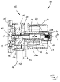
- FIG. 1 shows a section through part of a shading device 10, which has a console or a holder or a housing 25 on which an adjustment device 12 is arranged.
- the adjusting device 12 has a gear 14 , shown only schematically, which is attached to the housing 25 .
- a driven shaft 28 is provided, the rotational movement (double arrow B) of which is converted by the gear 14.
- the transmission 14 is in engagement with a transmission element 13 in the form of a driver shaft 16 via a first engagement device 20 .
- An opening 26 is provided in the transmission 14, into which the drive shaft 16 is inserted axially in such a way that a rotational movement of the transmission 14 can be transmitted to the drive shaft 16 via the first engagement device 20, i.e. that the transmission 14 and the drive shaft 16 can be connected by means of the first Engagement device 20 are rotatably engaged.
- the driver shaft 16 can be displaced in the axial direction, i.e. in the direction of its longitudinal axis L, as indicated by the double arrow C.
- roller tube 11 From a roller tube 11 only the so-called roller tube pin is shown. This sits firmly on a sleeve part 21, which has a bore 29 into which the driver shaft 16 is slidably inserted.
- the drive shaft 16 has an enlarged diameter section 16a which is slidably mounted in the bore 29 of the sleeve part 21 with a close fit.
- a second engagement device 22 is arranged on the end of the driver shaft 16 facing away from the transmission 14, which has an outer toothing 27 of the driver shaft 16, which engages with an inwardly directed toothing 30 of the sleeve part 21 in such a way that the driver shaft 16 is non-rotatable, however axially displaceable via the second engagement device with the sleeve part 21 and thus with the roller tube 11 is engaged.
- a spring 15, in particular a coiled spring 15, is arranged in the union nut 24 and carries a stop disk 23 on its side facing the driver shaft 16, which rests against the driver shaft 16 under the action of the spring 15 and/or is seated firmly on the driver shaft 16.
- the movement of the spring 15 is limited by the contact between the stop disk 23 and the sleeve part 21 .
- a braking device 18 (shown only schematically) is assigned to the fabric shaft 11, with which a braking force can be applied to the fabric shaft 11 so that the fabric shaft can only be rotated by applying relatively large torques, but the braking device 18 can also be designed such that the roller tube 11 can be set and locked in a desired position by a user.
- the fabric shaft 11 facing away, according to 1 The left end of the driver shaft 16 is arranged near an opening 31 in the housing 25 and is therefore accessible to a user from the outside of the housing 25 .
- FIG. 1 shows the functional position of the shading device 10.
- a rotational movement (double arrow B) applied to the driven shaft 28 is transmitted from the gear 14 to the driver shaft 16 via the first engagement device 20, so that the driver shaft 16 is rotated.
- the rotational movement of the driver shaft 16 is transmitted via the second engagement device 22 to the sleeve part 21 and thus to the fabric shaft 11, so that the fabric shaft 11 is rotated about an axis of rotation D, which is aligned with the longitudinal axis L of the fabric, in order to wind up or unwind a fabric (not shown). driver shaft collapses.
- the stop disk 23 is due to the force of the spring 15 facing away from the gear 14, according to FIG 1 Right side of the sleeve part 21, wherein the spring 15 at its opposite, according to 1 right end on the bottom of the union nut 24 is supported.
- the force of the spring 15 also acts on the driver shaft 16 and keeps it in the functional position.
- the user moves the driver shaft 16 to the in 2 shown release position.
- the user exercises on the Outside of the housing 25 accessible through the opening 31, according to 1 left end of the drive shaft 16 from a compressive force, as indicated by the arrow F.
- the driver shaft 16 is displaced axially in the direction of its longitudinal axis L until the 2 shown release position is reached.
- the transmission 14 is still non-rotatably, but axially displaceably engaged with the driver shaft 16 via the first engagement device 20 .
- the second engagement device 22 between the outer toothing 27 of the driver shaft 16 and the inner toothing 30 of the sleeve part 21 is disengaged by the axial displacement of the driver shaft 16, so that the sleeve part 21 together with the fabric shaft 11 can rotate freely on the section with the larger diameter 16a of the driver shaft 16 is seated.
- the displacement of the driver shaft 16 from the functional position according to 1 into the release position according to 2 takes place against the force of the spring 15.
- the axial displacement of the driver shaft 16 also causes the stop disk 23 to be displaced axially, so that the spring 15 is compressed and tensioned in the release position, as shown in 2 is shown.
- the user can activate the braking device 18 , by means of which the fabric shaft 11 is prevented from automatically rotating relative to the driver shaft 16 .
- the user can move the roller tube 11 relative to the driver shaft 16 and thus also relative to the Gear 14 and rotate relative to the driven shaft 28.
- the pressure force F acting from the outside on the driver shaft 16 is released, so that the driver shaft 16 moves into the in 1 functional position shown is axially displaced, in which the second engagement device 22 again connects the driver shaft 16 to the fabric shaft 11 in a rotationally fixed manner.
- the user can insert a tool from the outside of the housing 25 into the threaded hole 19 of the Screw in the driver shaft 16 and then manually apply a tensile force to the driver shaft 16, by which the driver shaft 16 is pushed back into the functional position.
Landscapes
- Engineering & Computer Science (AREA)
- Architecture (AREA)
- Structural Engineering (AREA)
- Civil Engineering (AREA)
- Gear Transmission (AREA)
- Mechanical Control Devices (AREA)
Applications Claiming Priority (1)
| Application Number | Priority Date | Filing Date | Title |
|---|---|---|---|
| DE102020131347.0A DE102020131347A1 (de) | 2020-11-26 | 2020-11-26 | Beschattungsvorrichtung |
Publications (2)
| Publication Number | Publication Date |
|---|---|
| EP4006257A1 true EP4006257A1 (fr) | 2022-06-01 |
| EP4006257B1 EP4006257B1 (fr) | 2024-02-07 |
Family
ID=77951630
Family Applications (1)
| Application Number | Title | Priority Date | Filing Date |
|---|---|---|---|
| EP21199039.5A Active EP4006257B1 (fr) | 2020-11-26 | 2021-09-27 | Dispositif d'ombrage |
Country Status (2)
| Country | Link |
|---|---|
| EP (1) | EP4006257B1 (fr) |
| DE (1) | DE102020131347A1 (fr) |
Citations (3)
| Publication number | Priority date | Publication date | Assignee | Title |
|---|---|---|---|---|
| DE2743075A1 (de) * | 1977-09-24 | 1979-03-29 | Kurt Till | Schwenkmarkise mit verstellantrieb |
| EP0694439A2 (fr) * | 1994-07-26 | 1996-01-31 | Carlo Maurizio Pozzi | Enrouleur pour auvents, en particulier pour véhicules à moteur |
| EP2817468A1 (fr) * | 2012-02-23 | 2014-12-31 | Teh Yor Co., Ltd. | Store de fenêtre et son module de commande |
Family Cites Families (4)
| Publication number | Priority date | Publication date | Assignee | Title |
|---|---|---|---|---|
| DE1764105U (de) | 1958-01-27 | 1958-03-27 | Metallbau A G | Storengetriebe mit winklig zueinander stehenden an- und abtriebswellen. |
| DE4318437A1 (de) | 1993-06-03 | 1994-12-08 | Rau Metall Gmbh & Co | Markise mit einem Tragprofil |
| DE102013108386A1 (de) | 2013-08-05 | 2015-02-05 | Gerhard Geiger GmbH & Co. KG | Hebewinde für Markisen, Rollläden, Jalousien und dergl. |
| JP6716286B2 (ja) | 2016-02-29 | 2020-07-01 | Bxテンパル株式会社 | オーニング装置 |
-
2020
- 2020-11-26 DE DE102020131347.0A patent/DE102020131347A1/de active Pending
-
2021
- 2021-09-27 EP EP21199039.5A patent/EP4006257B1/fr active Active
Patent Citations (3)
| Publication number | Priority date | Publication date | Assignee | Title |
|---|---|---|---|---|
| DE2743075A1 (de) * | 1977-09-24 | 1979-03-29 | Kurt Till | Schwenkmarkise mit verstellantrieb |
| EP0694439A2 (fr) * | 1994-07-26 | 1996-01-31 | Carlo Maurizio Pozzi | Enrouleur pour auvents, en particulier pour véhicules à moteur |
| EP2817468A1 (fr) * | 2012-02-23 | 2014-12-31 | Teh Yor Co., Ltd. | Store de fenêtre et son module de commande |
Also Published As
| Publication number | Publication date |
|---|---|
| EP4006257B1 (fr) | 2024-02-07 |
| DE102020131347A1 (de) | 2022-06-02 |
Similar Documents
| Publication | Publication Date | Title |
|---|---|---|
| EP1921246B1 (fr) | Dispositif de butée pour le mouvement d'ouverture et de fermeture d'une installation d'obscurcissement | |
| DE102007020000B4 (de) | Gurtaufroller | |
| DE112004001285T5 (de) | Seil-Aktuator für Lenden-Stütze | |
| DE29600996U1 (de) | Feststellbremse für Kraftfahrzeuge, Fahrzeuganhänger o.dgl. | |
| DE69500418T2 (de) | Trage- und Steuervorrichtung für ein Rollo | |
| DE60100767T2 (de) | Druckstückelementenanordnung für eine Kraftfahrzeug- Zahnstangenlenkung | |
| DE102004015825B4 (de) | Gurtaufroller für einen Fahrzeug-Sicherheitsgurt | |
| DE10324040A1 (de) | Handbremshebel | |
| DE102006049840B4 (de) | Gurtaufroller für einen Fahrzeuginsassen-Sicherheitsgurt | |
| DE2234321C2 (de) | Zahnärztliches Handstück | |
| EP4006257B1 (fr) | Dispositif d'ombrage | |
| DE102004009331A1 (de) | Betätigungsmechanismus für Bowdenzüge | |
| DE3917603A1 (de) | Bohrvorrichtung fuer hinterschnitt | |
| DE202004021544U1 (de) | Antrieb für eine Aufwickelanordnung eines Behangs | |
| EP1102908B1 (fr) | Arret de porte | |
| AT5643U1 (de) | Federwelle | |
| DE2834486A1 (de) | Verstellbare halterung fuer die arme einer gelenkarm-markise | |
| DE2115403C3 (de) | Seilspannungsregler fur Steuer seile | |
| DE19832502C2 (de) | Türfeststeller | |
| DE102014221741B4 (de) | Schwenkmodul einer Anhängerkupplung | |
| DE102005010211B4 (de) | Parksperrenmechanismus für ein Kraftfahrzeug, welches ein Automatgetriebe oder ein automatisiertes Handschaltgetriebe umfasst | |
| WO2015024607A1 (fr) | Dispositif permettant d'appliquer un couple sur un arbre | |
| DE102007002632B4 (de) | Kupplung für eine Wickelwelle eines Springrollos | |
| AT233797B (de) | Selbsthemmende Einrichtung zur Betätigung von Rolladen | |
| DE60310883T2 (de) | Verschluss mit versandszustand |
Legal Events
| Date | Code | Title | Description |
|---|---|---|---|
| PUAI | Public reference made under article 153(3) epc to a published international application that has entered the european phase |
Free format text: ORIGINAL CODE: 0009012 |
|
| STAA | Information on the status of an ep patent application or granted ep patent |
Free format text: STATUS: THE APPLICATION HAS BEEN PUBLISHED |
|
| AK | Designated contracting states |
Kind code of ref document: A1 Designated state(s): AL AT BE BG CH CY CZ DE DK EE ES FI FR GB GR HR HU IE IS IT LI LT LU LV MC MK MT NL NO PL PT RO RS SE SI SK SM TR |
|
| STAA | Information on the status of an ep patent application or granted ep patent |
Free format text: STATUS: REQUEST FOR EXAMINATION WAS MADE |
|
| 17P | Request for examination filed |
Effective date: 20221129 |
|
| RBV | Designated contracting states (corrected) |
Designated state(s): AL AT BE BG CH CY CZ DE DK EE ES FI FR GB GR HR HU IE IS IT LI LT LU LV MC MK MT NL NO PL PT RO RS SE SI SK SM TR |
|
| GRAP | Despatch of communication of intention to grant a patent |
Free format text: ORIGINAL CODE: EPIDOSNIGR1 |
|
| STAA | Information on the status of an ep patent application or granted ep patent |
Free format text: STATUS: GRANT OF PATENT IS INTENDED |
|
| INTG | Intention to grant announced |
Effective date: 20231025 |
|
| GRAS | Grant fee paid |
Free format text: ORIGINAL CODE: EPIDOSNIGR3 |
|
| GRAA | (expected) grant |
Free format text: ORIGINAL CODE: 0009210 |
|
| STAA | Information on the status of an ep patent application or granted ep patent |
Free format text: STATUS: THE PATENT HAS BEEN GRANTED |
|
| AK | Designated contracting states |
Kind code of ref document: B1 Designated state(s): AL AT BE BG CH CY CZ DE DK EE ES FI FR GB GR HR HU IE IS IT LI LT LU LV MC MK MT NL NO PL PT RO RS SE SI SK SM TR |
|
| REG | Reference to a national code |
Ref country code: GB Ref legal event code: FG4D Free format text: NOT ENGLISH |
|
| REG | Reference to a national code |
Ref country code: CH Ref legal event code: EP |
|
| REG | Reference to a national code |
Ref country code: IE Ref legal event code: FG4D Free format text: LANGUAGE OF EP DOCUMENT: GERMAN |
|
| REG | Reference to a national code |
Ref country code: DE Ref legal event code: R096 Ref document number: 502021002630 Country of ref document: DE |
|
| P01 | Opt-out of the competence of the unified patent court (upc) registered |
Effective date: 20240125 |
|
| REG | Reference to a national code |
Ref country code: LT Ref legal event code: MG9D |
|
| REG | Reference to a national code |
Ref country code: NL Ref legal event code: FP |
|
| PG25 | Lapsed in a contracting state [announced via postgrant information from national office to epo] |
Ref country code: IS Free format text: LAPSE BECAUSE OF FAILURE TO SUBMIT A TRANSLATION OF THE DESCRIPTION OR TO PAY THE FEE WITHIN THE PRESCRIBED TIME-LIMIT Effective date: 20240607 |
|
| PG25 | Lapsed in a contracting state [announced via postgrant information from national office to epo] |
Ref country code: LT Free format text: LAPSE BECAUSE OF FAILURE TO SUBMIT A TRANSLATION OF THE DESCRIPTION OR TO PAY THE FEE WITHIN THE PRESCRIBED TIME-LIMIT Effective date: 20240207 |
|
| PG25 | Lapsed in a contracting state [announced via postgrant information from national office to epo] |
Ref country code: GR Free format text: LAPSE BECAUSE OF FAILURE TO SUBMIT A TRANSLATION OF THE DESCRIPTION OR TO PAY THE FEE WITHIN THE PRESCRIBED TIME-LIMIT Effective date: 20240508 |
|
| PG25 | Lapsed in a contracting state [announced via postgrant information from national office to epo] |
Ref country code: HR Free format text: LAPSE BECAUSE OF FAILURE TO SUBMIT A TRANSLATION OF THE DESCRIPTION OR TO PAY THE FEE WITHIN THE PRESCRIBED TIME-LIMIT Effective date: 20240207 Ref country code: RS Free format text: LAPSE BECAUSE OF FAILURE TO SUBMIT A TRANSLATION OF THE DESCRIPTION OR TO PAY THE FEE WITHIN THE PRESCRIBED TIME-LIMIT Effective date: 20240507 |
|
| PG25 | Lapsed in a contracting state [announced via postgrant information from national office to epo] |
Ref country code: ES Free format text: LAPSE BECAUSE OF FAILURE TO SUBMIT A TRANSLATION OF THE DESCRIPTION OR TO PAY THE FEE WITHIN THE PRESCRIBED TIME-LIMIT Effective date: 20240207 |
|
| PG25 | Lapsed in a contracting state [announced via postgrant information from national office to epo] |
Ref country code: RS Free format text: LAPSE BECAUSE OF FAILURE TO SUBMIT A TRANSLATION OF THE DESCRIPTION OR TO PAY THE FEE WITHIN THE PRESCRIBED TIME-LIMIT Effective date: 20240507 Ref country code: NO Free format text: LAPSE BECAUSE OF FAILURE TO SUBMIT A TRANSLATION OF THE DESCRIPTION OR TO PAY THE FEE WITHIN THE PRESCRIBED TIME-LIMIT Effective date: 20240507 Ref country code: LT Free format text: LAPSE BECAUSE OF FAILURE TO SUBMIT A TRANSLATION OF THE DESCRIPTION OR TO PAY THE FEE WITHIN THE PRESCRIBED TIME-LIMIT Effective date: 20240207 Ref country code: IS Free format text: LAPSE BECAUSE OF FAILURE TO SUBMIT A TRANSLATION OF THE DESCRIPTION OR TO PAY THE FEE WITHIN THE PRESCRIBED TIME-LIMIT Effective date: 20240607 Ref country code: HR Free format text: LAPSE BECAUSE OF FAILURE TO SUBMIT A TRANSLATION OF THE DESCRIPTION OR TO PAY THE FEE WITHIN THE PRESCRIBED TIME-LIMIT Effective date: 20240207 Ref country code: GR Free format text: LAPSE BECAUSE OF FAILURE TO SUBMIT A TRANSLATION OF THE DESCRIPTION OR TO PAY THE FEE WITHIN THE PRESCRIBED TIME-LIMIT Effective date: 20240508 Ref country code: FI Free format text: LAPSE BECAUSE OF FAILURE TO SUBMIT A TRANSLATION OF THE DESCRIPTION OR TO PAY THE FEE WITHIN THE PRESCRIBED TIME-LIMIT Effective date: 20240207 Ref country code: ES Free format text: LAPSE BECAUSE OF FAILURE TO SUBMIT A TRANSLATION OF THE DESCRIPTION OR TO PAY THE FEE WITHIN THE PRESCRIBED TIME-LIMIT Effective date: 20240207 Ref country code: BG Free format text: LAPSE BECAUSE OF FAILURE TO SUBMIT A TRANSLATION OF THE DESCRIPTION OR TO PAY THE FEE WITHIN THE PRESCRIBED TIME-LIMIT Effective date: 20240207 |
|
| PG25 | Lapsed in a contracting state [announced via postgrant information from national office to epo] |
Ref country code: PL Free format text: LAPSE BECAUSE OF FAILURE TO SUBMIT A TRANSLATION OF THE DESCRIPTION OR TO PAY THE FEE WITHIN THE PRESCRIBED TIME-LIMIT Effective date: 20240207 Ref country code: PT Free format text: LAPSE BECAUSE OF FAILURE TO SUBMIT A TRANSLATION OF THE DESCRIPTION OR TO PAY THE FEE WITHIN THE PRESCRIBED TIME-LIMIT Effective date: 20240607 |
|
| PG25 | Lapsed in a contracting state [announced via postgrant information from national office to epo] |
Ref country code: SE Free format text: LAPSE BECAUSE OF FAILURE TO SUBMIT A TRANSLATION OF THE DESCRIPTION OR TO PAY THE FEE WITHIN THE PRESCRIBED TIME-LIMIT Effective date: 20240207 Ref country code: PT Free format text: LAPSE BECAUSE OF FAILURE TO SUBMIT A TRANSLATION OF THE DESCRIPTION OR TO PAY THE FEE WITHIN THE PRESCRIBED TIME-LIMIT Effective date: 20240607 Ref country code: PL Free format text: LAPSE BECAUSE OF FAILURE TO SUBMIT A TRANSLATION OF THE DESCRIPTION OR TO PAY THE FEE WITHIN THE PRESCRIBED TIME-LIMIT Effective date: 20240207 Ref country code: LV Free format text: LAPSE BECAUSE OF FAILURE TO SUBMIT A TRANSLATION OF THE DESCRIPTION OR TO PAY THE FEE WITHIN THE PRESCRIBED TIME-LIMIT Effective date: 20240207 |
|
| PG25 | Lapsed in a contracting state [announced via postgrant information from national office to epo] |
Ref country code: DK Free format text: LAPSE BECAUSE OF FAILURE TO SUBMIT A TRANSLATION OF THE DESCRIPTION OR TO PAY THE FEE WITHIN THE PRESCRIBED TIME-LIMIT Effective date: 20240207 |
|
| PG25 | Lapsed in a contracting state [announced via postgrant information from national office to epo] |
Ref country code: SM Free format text: LAPSE BECAUSE OF FAILURE TO SUBMIT A TRANSLATION OF THE DESCRIPTION OR TO PAY THE FEE WITHIN THE PRESCRIBED TIME-LIMIT Effective date: 20240207 |
|
| PG25 | Lapsed in a contracting state [announced via postgrant information from national office to epo] |
Ref country code: CZ Free format text: LAPSE BECAUSE OF FAILURE TO SUBMIT A TRANSLATION OF THE DESCRIPTION OR TO PAY THE FEE WITHIN THE PRESCRIBED TIME-LIMIT Effective date: 20240207 Ref country code: EE Free format text: LAPSE BECAUSE OF FAILURE TO SUBMIT A TRANSLATION OF THE DESCRIPTION OR TO PAY THE FEE WITHIN THE PRESCRIBED TIME-LIMIT Effective date: 20240207 |
|
| PG25 | Lapsed in a contracting state [announced via postgrant information from national office to epo] |
Ref country code: SK Free format text: LAPSE BECAUSE OF FAILURE TO SUBMIT A TRANSLATION OF THE DESCRIPTION OR TO PAY THE FEE WITHIN THE PRESCRIBED TIME-LIMIT Effective date: 20240207 |
|
| PG25 | Lapsed in a contracting state [announced via postgrant information from national office to epo] |
Ref country code: SM Free format text: LAPSE BECAUSE OF FAILURE TO SUBMIT A TRANSLATION OF THE DESCRIPTION OR TO PAY THE FEE WITHIN THE PRESCRIBED TIME-LIMIT Effective date: 20240207 Ref country code: SK Free format text: LAPSE BECAUSE OF FAILURE TO SUBMIT A TRANSLATION OF THE DESCRIPTION OR TO PAY THE FEE WITHIN THE PRESCRIBED TIME-LIMIT Effective date: 20240207 Ref country code: RO Free format text: LAPSE BECAUSE OF FAILURE TO SUBMIT A TRANSLATION OF THE DESCRIPTION OR TO PAY THE FEE WITHIN THE PRESCRIBED TIME-LIMIT Effective date: 20240207 Ref country code: EE Free format text: LAPSE BECAUSE OF FAILURE TO SUBMIT A TRANSLATION OF THE DESCRIPTION OR TO PAY THE FEE WITHIN THE PRESCRIBED TIME-LIMIT Effective date: 20240207 Ref country code: DK Free format text: LAPSE BECAUSE OF FAILURE TO SUBMIT A TRANSLATION OF THE DESCRIPTION OR TO PAY THE FEE WITHIN THE PRESCRIBED TIME-LIMIT Effective date: 20240207 Ref country code: CZ Free format text: LAPSE BECAUSE OF FAILURE TO SUBMIT A TRANSLATION OF THE DESCRIPTION OR TO PAY THE FEE WITHIN THE PRESCRIBED TIME-LIMIT Effective date: 20240207 |
|
| REG | Reference to a national code |
Ref country code: DE Ref legal event code: R097 Ref document number: 502021002630 Country of ref document: DE |
|
| PLBE | No opposition filed within time limit |
Free format text: ORIGINAL CODE: 0009261 |
|
| STAA | Information on the status of an ep patent application or granted ep patent |
Free format text: STATUS: NO OPPOSITION FILED WITHIN TIME LIMIT |
|
| 26N | No opposition filed |
Effective date: 20241108 |
|
| PG25 | Lapsed in a contracting state [announced via postgrant information from national office to epo] |
Ref country code: MC Free format text: LAPSE BECAUSE OF FAILURE TO SUBMIT A TRANSLATION OF THE DESCRIPTION OR TO PAY THE FEE WITHIN THE PRESCRIBED TIME-LIMIT Effective date: 20240207 Ref country code: SI Free format text: LAPSE BECAUSE OF FAILURE TO SUBMIT A TRANSLATION OF THE DESCRIPTION OR TO PAY THE FEE WITHIN THE PRESCRIBED TIME-LIMIT Effective date: 20240207 |
|
| PG25 | Lapsed in a contracting state [announced via postgrant information from national office to epo] |
Ref country code: LU Free format text: LAPSE BECAUSE OF NON-PAYMENT OF DUE FEES Effective date: 20240927 |
|
| PG25 | Lapsed in a contracting state [announced via postgrant information from national office to epo] |
Ref country code: IE Free format text: LAPSE BECAUSE OF NON-PAYMENT OF DUE FEES Effective date: 20240927 |
|
| REG | Reference to a national code |
Ref country code: CH Ref legal event code: U11 Free format text: ST27 STATUS EVENT CODE: U-0-0-U10-U11 (AS PROVIDED BY THE NATIONAL OFFICE) Effective date: 20251001 |
|
| PGFP | Annual fee paid to national office [announced via postgrant information from national office to epo] |
Ref country code: DE Payment date: 20250910 Year of fee payment: 5 |
|
| PGFP | Annual fee paid to national office [announced via postgrant information from national office to epo] |
Ref country code: NL Payment date: 20250922 Year of fee payment: 5 |
|
| PGFP | Annual fee paid to national office [announced via postgrant information from national office to epo] |
Ref country code: BE Payment date: 20250919 Year of fee payment: 5 |
|
| PGFP | Annual fee paid to national office [announced via postgrant information from national office to epo] |
Ref country code: AT Payment date: 20251020 Year of fee payment: 5 Ref country code: FR Payment date: 20250925 Year of fee payment: 5 |
|
| PGFP | Annual fee paid to national office [announced via postgrant information from national office to epo] |
Ref country code: IT Payment date: 20250930 Year of fee payment: 5 |
|
| PGFP | Annual fee paid to national office [announced via postgrant information from national office to epo] |
Ref country code: CH Payment date: 20251001 Year of fee payment: 5 |
|
| PG25 | Lapsed in a contracting state [announced via postgrant information from national office to epo] |
Ref country code: CY Free format text: LAPSE BECAUSE OF FAILURE TO SUBMIT A TRANSLATION OF THE DESCRIPTION OR TO PAY THE FEE WITHIN THE PRESCRIBED TIME-LIMIT; INVALID AB INITIO Effective date: 20210927 |
|
| PG25 | Lapsed in a contracting state [announced via postgrant information from national office to epo] |
Ref country code: HU Free format text: LAPSE BECAUSE OF FAILURE TO SUBMIT A TRANSLATION OF THE DESCRIPTION OR TO PAY THE FEE WITHIN THE PRESCRIBED TIME-LIMIT; INVALID AB INITIO Effective date: 20210927 |