EP4006274B1 - Türverriegelungsvorrichtung - Google Patents
Türverriegelungsvorrichtung Download PDFInfo
- Publication number
- EP4006274B1 EP4006274B1 EP19939501.3A EP19939501A EP4006274B1 EP 4006274 B1 EP4006274 B1 EP 4006274B1 EP 19939501 A EP19939501 A EP 19939501A EP 4006274 B1 EP4006274 B1 EP 4006274B1
- Authority
- EP
- European Patent Office
- Prior art keywords
- switch
- position switch
- contact hole
- lever
- disposed
- Prior art date
- Legal status (The legal status is an assumption and is not a legal conclusion. Google has not performed a legal analysis and makes no representation as to the accuracy of the status listed.)
- Active
Links
Images


Classifications
-
- E—FIXED CONSTRUCTIONS
- E05—LOCKS; KEYS; WINDOW OR DOOR FITTINGS; SAFES
- E05B—LOCKS; ACCESSORIES THEREFOR; HANDCUFFS
- E05B81/00—Power-actuated vehicle locks
- E05B81/54—Electrical circuits
- E05B81/64—Monitoring or sensing, e.g. by using switches or sensors
- E05B81/72—Monitoring or sensing, e.g. by using switches or sensors the lock status, i.e. locked or unlocked condition
-
- E—FIXED CONSTRUCTIONS
- E05—LOCKS; KEYS; WINDOW OR DOOR FITTINGS; SAFES
- E05B—LOCKS; ACCESSORIES THEREFOR; HANDCUFFS
- E05B81/00—Power-actuated vehicle locks
- E05B81/54—Electrical circuits
- E05B81/64—Monitoring or sensing, e.g. by using switches or sensors
- E05B81/66—Monitoring or sensing, e.g. by using switches or sensors the bolt position, i.e. the latching status
- E05B81/68—Monitoring or sensing, e.g. by using switches or sensors the bolt position, i.e. the latching status by sensing the position of the detent
-
- E—FIXED CONSTRUCTIONS
- E05—LOCKS; KEYS; WINDOW OR DOOR FITTINGS; SAFES
- E05B—LOCKS; ACCESSORIES THEREFOR; HANDCUFFS
- E05B81/00—Power-actuated vehicle locks
- E05B81/02—Power-actuated vehicle locks characterised by the type of actuators used
- E05B81/04—Electrical
- E05B81/06—Electrical using rotary motors
-
- E—FIXED CONSTRUCTIONS
- E05—LOCKS; KEYS; WINDOW OR DOOR FITTINGS; SAFES
- E05B—LOCKS; ACCESSORIES THEREFOR; HANDCUFFS
- E05B81/00—Power-actuated vehicle locks
- E05B81/12—Power-actuated vehicle locks characterised by the function or purpose of the powered actuators
- E05B81/14—Power-actuated vehicle locks characterised by the function or purpose of the powered actuators operating on bolt detents, e.g. for unlatching the bolt
-
- E—FIXED CONSTRUCTIONS
- E05—LOCKS; KEYS; WINDOW OR DOOR FITTINGS; SAFES
- E05B—LOCKS; ACCESSORIES THEREFOR; HANDCUFFS
- E05B81/00—Power-actuated vehicle locks
- E05B81/54—Electrical circuits
- E05B81/64—Monitoring or sensing, e.g. by using switches or sensors
-
- E—FIXED CONSTRUCTIONS
- E05—LOCKS; KEYS; WINDOW OR DOOR FITTINGS; SAFES
- E05B—LOCKS; ACCESSORIES THEREFOR; HANDCUFFS
- E05B81/00—Power-actuated vehicle locks
- E05B81/54—Electrical circuits
- E05B81/64—Monitoring or sensing, e.g. by using switches or sensors
- E05B81/72—Monitoring or sensing, e.g. by using switches or sensors the lock status, i.e. locked or unlocked condition
- E05B81/74—Monitoring or sensing, e.g. by using switches or sensors the lock status, i.e. locked or unlocked condition by sensing the state of the actuator
-
- E—FIXED CONSTRUCTIONS
- E05—LOCKS; KEYS; WINDOW OR DOOR FITTINGS; SAFES
- E05B—LOCKS; ACCESSORIES THEREFOR; HANDCUFFS
- E05B81/00—Power-actuated vehicle locks
- E05B81/54—Electrical circuits
- E05B81/90—Manual override in case of power failure
-
- H—ELECTRICITY
- H01—ELECTRIC ELEMENTS
- H01H—ELECTRIC SWITCHES; RELAYS; SELECTORS; EMERGENCY PROTECTIVE DEVICES
- H01H1/00—Contacts
- H01H1/12—Contacts characterised by the manner in which co-operating contacts engage
- H01H1/14—Contacts characterised by the manner in which co-operating contacts engage by abutting
-
- H—ELECTRICITY
- H01—ELECTRIC ELEMENTS
- H01H—ELECTRIC SWITCHES; RELAYS; SELECTORS; EMERGENCY PROTECTIVE DEVICES
- H01H13/00—Switches having rectilinearly-movable operating part or parts adapted for pushing or pulling in one direction only, e.g. push-button switch
- H01H13/50—Switches having rectilinearly-movable operating part or parts adapted for pushing or pulling in one direction only, e.g. push-button switch having a single operating member
- H01H13/503—Stacked switches
-
- H—ELECTRICITY
- H01—ELECTRIC ELEMENTS
- H01H—ELECTRIC SWITCHES; RELAYS; SELECTORS; EMERGENCY PROTECTIVE DEVICES
- H01H13/00—Switches having rectilinearly-movable operating part or parts adapted for pushing or pulling in one direction only, e.g. push-button switch
- H01H13/02—Details
- H01H13/12—Movable parts; Contacts mounted thereon
- H01H13/14—Operating parts, e.g. push-button
- H01H13/18—Operating parts, e.g. push-button adapted for actuation at a limit or other predetermined position in the path of a body, the relative movement of switch and body being primarily for a purpose other than the actuation of the switch, e.g. door switch, limit switch, floor-levelling switch of a lift
-
- H—ELECTRICITY
- H01—ELECTRIC ELEMENTS
- H01H—ELECTRIC SWITCHES; RELAYS; SELECTORS; EMERGENCY PROTECTIVE DEVICES
- H01H9/00—Details of switching devices, not covered by groups H01H1/00 - H01H7/00
- H01H2009/0083—Details of switching devices, not covered by groups H01H1/00 - H01H7/00 using redundant components, e.g. two pressure tubes for pressure switch
-
- H—ELECTRICITY
- H01—ELECTRIC ELEMENTS
- H01H—ELECTRIC SWITCHES; RELAYS; SELECTORS; EMERGENCY PROTECTIVE DEVICES
- H01H9/00—Details of switching devices, not covered by groups H01H1/00 - H01H7/00
- H01H9/16—Indicators for switching condition, e.g. "on" or "off"
- H01H9/167—Circuits for remote indication
Definitions
- the present invention relates to a door latch device for closing and opening a vehicle door.
- a door latch device of a vehicle includes a latch mechanism that latches and unlatches a striker disposed on a main body side of the vehicle, and closes and opens a door by the latch mechanism.
- Patent Literature 1 discloses a door latch device including an electric release mechanism that can release engagement between a latch mechanism and a striker by power of a motor, a manual release mechanism that can release engagement of the latch mechanism by manual operation force, and a lock mechanism that can switch between a locked state that disables a release function of the manual release mechanism and an unlocked state that enables the same.
- the lock mechanism is used only for the function of the manual release mechanism, and is always used in the locked state and switched to the unlocked state for a predetermined situation.
- the locked state and the unlocked state of the lock mechanism are switched by normal rotation and reverse rotation of a cam wheel rotated by power of the motor.
- the cam wheel is held at a reference position by energizing force of a neutral return spring, and has a configuration for switching the lock mechanism to the locked state when normally rotated from the reference position, and switching the lock mechanism to the unlocked state when reversely rotated from the reference position.
- cam wheel also releases engagement of the latch mechanism when normally rotated from the reference position. Due to this, the lock mechanism can be switched, and the engagement of the latch mechanism can be released by a single motor.
- some door latch devices for closing and opening the vehicle door include electric components such as a motor and a position switch (refer to Patent Literature 2).
- the position switch is set to detect an operation of a predetermined object to be detected, and detects whether a component of the lock mechanism is at a position indicating the locked state or a position indicating the unlocked state, for example.
- a detection signal of the position switch is supplied to a predetermined circuit board, and control based thereon is performed.
- Patent Literature 1 of what is called a knob-less type not including a locking/unlocking knob for manually switching the lock mechanism
- manual switching to an unlocked state using a key and switching to the unlocked state by power of the motor are not required to be used unless a predetermined situation is caused.
- the lock mechanism does not work by a normal operation, and is maintained in the locked state for a long time.
- grease is hardened due to long-term deterioration, or a spring, a lever, and the like made of steel material rust, and the lock mechanism does not smoothly function in a predetermined situation.
- an operation of the object to be detected is detected by the position switch, the detection signal is read by a CPU, and control based on the detection signal is performed. If the position switch breaks down, the operation of the object to be detected cannot be detected, so that there is the inconvenience that control related thereto is not performed.
- the present invention is made in view of the problem described above, and provides a door latch device that can detect an operation of an object to be detected more securely.
- a door latch device includes: a first position switch and a second position switch, each of the first position switch and the second position switch including a first contact hole connected to one of a normally open contact or a normally closed contact, a second contact hole connected to a contact having a reverse format of the first contact hole, and a common contact hole connected to a common contact, wherein the first contact hole, the second contact hole and the common contact hole are arranged on a straight line, the first position switch and the second position switch are disposed at positions shifted from each other along the straight line and stacked in a piercing direction of the first contact hole, the second contact hole, and the common contact; a common pin configured to be electrically conducted to the common contact hole of the first position switch and the first contact hole of the second position switch by being inserted therein; a first signal pin configured to be electrically conducted to the first contact hole of the first position switch by being inserted therein; and a second signal pin configured to be electrically
- the door latch device may include a circuit board, and each of the common pin, the first signal pin and the second signal pin may be erected from the circuit board.
- a space in which the circuit board may be disposed and a space in which the first position switch and the second position switch are disposed are partitioned with a partition plate, and the first signal pin, the second signal pin and the common pin may be configured to pierce pin holes formed on the partition plate and project from one of the spaces to another one of the spaces.
- waterproof treatment may be applied to the space in which the first position switch and the second position switch are disposed, around the pin holes.
- the operation detection target may include a first cam configured to act on an actuator of the first position switch, and a second cam configured to act on an actuator of the second position switch, and the first cam and the second cam may be shifted from each other in a stacking direction of the first position switch and the second position switch, and be disposed at positions shifted from each other along the straight line.
- the door latch device may includes a latch mechanism configured to hold a door of a vehicle in a closed state; an electric release unit configured to release the latch mechanism by power of a motor; a manual release unit configured to release the latch mechanism by manual operation force; and a lock mechanism configured to switch between a locked state for disabling a function of the manual release unit and an unlocked state for enabling the same, and the operation detection target may be a component whose position is switched depending on whether the lock mechanism is in the locked state or the unlocked state, and the first position switch and the second position switch may be configured to detect whether the operation detection target is in the locked state or the Advantageous Effects of Invention
- the operation of the object to be detected is read twice by a stacked first position switch and second position switch, and the operation thereof can be detected more securely.
- a door latch device 10 In the following description, representation of directions in the description of a door latch device 10 is based on the vehicle. As the directions based on the vehicle, upward and downward, inward and outward (that is, an indoor side and an outdoor side), and forward and rearward are indicated by arrows when appropriate in the drawings. Representation of a rotation direction (a clockwise direction, a counterclockwise direction) of a rotary component basically corresponds to the drawing that is referred to at the present point.
- the door latch device 10 exemplified in each of the drawings is a door latch device applied to a right side door of the vehicle, but a door latch device applied to a left side door may have a symmetrical structure.
- FIG. 1 is a perspective view of the door latch device 10 according to the present embodiment viewed from obliquely rearward
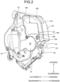
- FIG. 2 is a perspective view of the door latch device 10 viewed from obliquely forward on the outside of the vehicle.
- the door latch device 10 is attached to an inner part of the door of the vehicle, and closes and opens the door by latching and unlatching a striker disposed on a main body side of the vehicle.
- the door latch device 10 is disposed to latch the striker on a side door of the vehicle, but the "door” has a broad sense, and may be applied to a hood, a trunk lid, a tail gate, and the like.
- the following describes a schematic entire configuration of the door latch device 10.
- a latch 12 that latches the striker is disposed at the back of a striker entry groove 14.
- the latch 12 is part of a latch mechanism 44 described later.
- the striker entry groove 14 is formed as part of a cover plate 16.
- a body 18 is disposed around the cover plate 16. An inner side and a rear side of the latch mechanism 44 are covered by the cover plate 16 and the body 18.
- the door latch device 10 is covered by a case 20, a first cover 22, and a second cover 24 in addition to the cover plate 16 and the body 18 described above.
- the case 20 mainly covers an outer side
- the first cover 22 mainly covers an inner side
- the second cover 24 further covers a forward upper part of the inner side of the case 20.
- the cover plate 16, the body 18, the case 20, the first cover 22, and the second cover 24 form a housing of the door latch device 10.
- the door latch device 10 further includes a waterproof cover 26 that covers an upper surface, a cable cover 28 on an inner lower side, a coupler 30 disposed on an inner upper part, and a key cylinder coupling part 32 disposed on an outer upper part.
- the waterproof cover 26 covers a boundary part between the case 20 and the first cover 22, and the second cover 24 from above to prevent entry of waterdrops.
- the cable cover 28 covers a connecting portion for a cable 35.
- the cable 35 is connected to an inner handle (not illustrated).
- a harness connector (not illustrated) is connected to the coupler 30.
- a sponge may be disposed around the coupler 30.
- the key cylinder coupling part 32 is a portion into which a key is inserted to be operated.
- An end part of an outer lever 34 connected to an outer handle (not illustrated) is exposed to an outer surface of the door latch device 10.
- FIG. 3 is a side view illustrating an inner part of the door latch device 10.
- FIG. 3 illustrates the door latch device 10 in a state in which the body 18, the first cover 22, the waterproof cover 26, and the cable cover 28 are removed.
- a first housing space 36 is formed inside the door latch device 10.
- the first housing space 36 is a region the outer side of which is covered by the case 20, and the inner side thereof is mainly covered by the first cover 22.
- the inner side of the first housing space 36 is covered by the cover plate 16, the body 18, and the cable cover 28 in addition to the first cover 22.
- the first housing space 36 can be briefly partitioned into a mechanism region 40 in which a machine mechanism 38 is disposed, and an electric component region 42 in which electric components are disposed.
- the electric component region 42 occupies a forward upper part, and the mechanism region 40 occupies a remaining portion.
- the machine mechanism 38 includes a latch mechanism 44 that latches and unlatches the striker with the latch 12, and a lock mechanism 46 that causes the latch mechanism 44 to be in a locked state and an unlocked state.
- the latch mechanism 44 is disposed rearward in the first housing space 36, and covered by the cover plate 16 and the body 18.
- a second housing space 124 (refer to FIG. 10 ) is formed in addition to the first housing space 36.
- the second housing space 124 will be described later.
- the machine mechanism 38 also includes an electric release unit that can release the latch mechanism 44 by power of a motor 94, and a manual release unit that can release the latch mechanism 44 by manual operation force.
- the electric release unit is a unit that includes the motor 94, a cam wheel 76, and the like (described later), and unlatches the striker.
- the manual release unit is a unit that unlatches the striker via the outer lever 34 that mechanically interlocks with a manual operation and an inner lever 59 (described later).
- FIG. 4 is a perspective view of the latch mechanism 44.
- the latch mechanism 44 includes a base bracket 50, a ratchet 52, a ratchet holder 54, a ratchet lever 56, an anti-panic lever 58, and the inner lever 59 in addition to the latch 12 and the outer lever 34 described above.
- Each element of the latch mechanism 44 is supported or pivotally supported by the base bracket 50.
- the latch 12 is pivotally supported by a shaft part 60, and includes a striker engagement groove 12a and a ratchet engagement part 12b.
- the latch 12 rotates against a spring (not illustrated) when the striker enters the striker engagement groove 12a from a door-opened state, latches the striker at a full-latch position when the ratchet 52 engages with the ratchet engagement part 12b, and closes the door.
- the ratchet 52 includes a base lever 64 pivotally supported by a shaft part 62, and a pole lever 66 including a base shaft part 66a pivotally supported by the base lever 64.
- the base lever 64 is elastically energized by a spring 65.
- the pole lever 66 bends within a predetermined angle range with respect to the base lever 64.
- the ratchet 52 is supported by the ratchet holder 54 from a side to hold a substantially linear attitude of the ratchet 52, and a distal end of the pole lever 66 engages with the ratchet engagement part 12b to hold the latch 12 at the full-latch position.
- the ratchet holder 54 is pivotally supported by a shaft part 68, and elastically energized by a spring 70 to laterally support the base lever 64.
- the ratchet holder 54 rotates against elastic force of the spring 70 based on an operation of the ratchet lever 56, and is separated from the base lever 64.
- the base lever 64 and the pole lever 66 of the ratchet 52 are then caused to be in a buckling state with respect to the base shaft part 66a, and the pole lever 66 is detached from the ratchet engagement part 12b to open the latch 12.
- the latch 12 rotates by elastic force to unlatch the striker, and opens the door.
- the ratchet lever 56 is pivotally supported by the base bracket 50, and includes a passive part 56a projecting inward from a rotor shaft, and an action part 56b projecting outward from the rotor shaft.
- the action part 56b rotates the ratchet holder 54 when the passive part 56a moves upward.
- the outer lever 34 is pivotally supported by a shaft part 72, and includes a handle operating part 34a projecting outward from the shaft part 72, and an action part 34b and a lever passive piece 34c projecting inward from the shaft part 72.
- the handle operating part 34a is a portion operated by the outer handle.
- the action part 34b is inserted into a hole 58a of the anti-panic lever 58, and acts on the anti-panic lever 58.
- the action part 34b is also inserted into a deformed hole 80b of an open link 80 (described later).
- the lever passive piece 34c is disposed below the action part 34b, and operated by the inner lever 59.
- the outer lever 34 is rotated by an operation of the handle operating part 34a or the lever passive piece 34c, and pushes up the anti-panic lever 58.
- the inner lever 59 is pivotally supported by a shaft part 74, and is swung when the cable 35 is operated, whereby an operation piece 59a pushes up the lever passive piece 34c.
- the anti-panic lever 58 includes the hole 58a into which the action part 34b is inserted, and an action piece 58b bent at an upper part.
- the anti-panic lever 58 is pushed up by the action part 34b due to rotation of the outer lever 34 when the open link 80 (described later) is at an unlocked position, and the action piece 58b pushes up the passive part 56a of the ratchet lever 56. Due to this, the ratchet holder 54 and the ratchet 52 perform an unlatch operation.
- the anti-panic lever 58 has a structure separated from the open link 80 for an anti-panic mechanism.
- FIG. 5 is a perspective view of the lock mechanism 46 viewed from obliquely inside rearward
- FIG. 6 is a perspective view of the lock mechanism 46 viewed from obliquely outside forward.
- the case 20 is also briefly illustrated so that arrangement of the lock mechanism 46 can be understood.
- the lock mechanism 46 is in the locked state.
- the lock mechanism 46 includes a cam wheel 76 pivotally supported by a shaft part 76a, a cam lever 78 that is pivotally supported by a shaft part 78a and driven by the cam wheel 76, the open link (position switching member) 80 driven by the cam lever 78, a sub-lock lever 82 interlocking with the open link 80, and an open lever 84 that is pivotally supported by a shaft part 84a and driven by the cam wheel 76.
- the lock mechanism 46 further includes a lock lever 86 and an auxiliary lever 88 interlocking with the sub-lock lever 82, and a key lever 90 and a sub-key lever 92 that interlock with a key operation to drive the sub-lock lever 82.
- the lock lever 86 is represented by a dark dot pattern
- the open link 80 is represented by a light dot pattern.
- the cam wheel 76 has a disk shape, and rotates when teeth disposed on an outer peripheral surface are driven by a worm 94a of a rotor shaft of the motor 94. The teeth are not illustrated.
- the motor 94 is disposed in the electric component region 42 (refer to FIG. 3 ).
- a rotation direction of the cam wheel 76 is represented such that a clockwise direction indicates normal rotation, and a counterclockwise direction indicates reverse rotation based on FIG. 5 .
- the cam wheel 76 includes a cam 76b.
- the cam 76b has a shape having a diameter that gradually increases, from immediately below the shaft part 76a in the counterclockwise direction across about 270°, when the cam wheel 76 is at a reference position. The diameter thereof is close to a radius of the cam wheel 76 at a position of about 270°, and the diameter is maintained in the counterclockwise direction to a position of about 180°.
- an auxiliary component 77 is disposed on an inner surface of the cam wheel 76.
- the cam wheel 76 and the auxiliary component 77 are fixed to be substantially one component.
- a spring 76c is disposed inside a sleeve 77a formed of the auxiliary component 77. The spring 76c energizes the cam wheel 76 to be at a neutral reference position.
- the cam wheel 76 can normally rotate and reversely rotate against the spring 76c from the reference position due to action of the motor 94.
- the auxiliary component 77 includes a projection 77b projecting inward from an outer circumference vicinity part, and a first inclined wall 77c disposed on substantially the opposite side of the projection 77b.
- the projection 77b abuts on an elastic stopper 96 disposed in the case 20 (refer to FIG. 2 ) when the cam wheel 76 reversely rotates, and restricts rotation of the cam wheel 76.
- the first inclined wall 77c is formed such that the width thereof is increased in the counterclockwise direction from a sleeve surface of the sleeve 77a in a radial direction.
- the cam wheel 76 further includes a second inclined wall 76d and a holding wall 76e.
- the second inclined wall 76d is formed such that the width thereof is increased in the clockwise direction from the sleeve surface of the sleeve 77a in the radial direction.
- the first inclined wall 77c and the second inclined wall 76d are formed to be opposed to each other at close positions, and are inclined in reverse directions.
- the first inclined wall 77c is disposed on an outer side as compared with the second inclined wall 76d.
- the holding wall 76e is a wall having a circular arc shape that is disposed on a side slightly closer to the counterclockwise direction than the second inclined wall 76d, and projects outward along a peripheral surface of the cam wheel 76. As illustrated in FIG. 6 , a clockwise direction side of the holding wall 76e is closed, and a counterclockwise direction side thereof is opened.
- a lower surface 78d of the cam lever 78 abuts on the cam 76b, and when the cam wheel 76 rotates, the cam lever 78 is driven by the cam 76b to swing against a spring 78b in the counterclockwise direction.
- a knob 78c at a distal end of the cam lever 78 is fitted into a side surface guide groove 80a of the open link 80, and erects the inclined open link 80 when the cam lever 78 swings in the clockwise direction.
- the deformed hole 80b is formed at a lower end of the open link 80.
- the action part 34b of the outer lever 34 (refer to FIG. 4 ) is inserted into the deformed hole 80b, and the open link 80 is lifted up by an operation of the outer lever 34.
- the anti-panic lever 58 is assembled to a lower end of the open link 80, and moves up and down, and is inclined integrally with the open link 80.
- the open link 80 is a component to be switched to a locked position of an inclined attitude (an attitude in FIG. 5 ) and an unlocked position of an erected attitude (refer to FIG. 8(b) ) by the cam lever 78.
- the lock mechanism 46 is caused to be in a locked state when the open link 80 is at the locked position, and the lock mechanism 46 is caused to be in an unlocked state when the open link 80 is at the unlocked position.
- a position of the open link 80 is switched by the lock lever 86.
- the anti-panic lever 58 does not abut on the ratchet lever 56 (refer to FIG. 4 ) even in a case of being lifted up by the outer lever 34 because the anti-panic lever 58 is inclined together with the open link 80, that is, an attempt fails.
- the ratchet lever 56 does not operate, and the door is kept being closed as the locked state.
- the anti-panic lever 58 is erected together with the open link 80, so that the anti-panic lever 58 abuts on and pushes up the ratchet lever 56.
- the ratchet lever 56 operates to cause the unlocked state in which the door may be opened.
- the sub-lock lever 82 is pivotally supported by a shaft part 82a to be able to swing, and is swung and driven by the key lever 90 and the sub-key lever 92 to switch between the locked position and the unlocked position of the open link 80. That is, the sub-lock lever 82 can switch between the locked state and the unlocked state.
- the sub-lock lever 82 swings in the counterclockwise direction under action of the key lever 90 and the sub-key lever 92, an upper portion of the open link 80 is pushed out from the sub-lock lever 82 via an inner knob 86i (refer to FIG. 7(d) ) of the lock lever 86, and swings in the clockwise direction to be at the unlocked position.
- the open lever 84 is a component used for opening the door based on electric release, that is, a switch operation and the like performed by a driver.
- the open lever 84 includes a cam passive part 84b projecting forward and a ratchet operation part 84c projecting rearward, and is energized in the clockwise direction by a spring 84d.
- the cam wheel 76 normally rotates, the cam 76b pushes down the cam passive part 84b, the open lever 84 rotates against the spring 84d in the counterclockwise direction about the shaft part 84a, and the ratchet operation part 84c moves upward.
- the open lever 84 can operate the ratchet lever 56 independently of the open link 80. Thus, with the open lever 84, the door can be opened based on the electric release unit even when the lock mechanism 46 is in the locked state (that is, the open link 80 is at the locked position).
- the lock lever 86 is pivotally supported by a shaft part 86a, and includes an arm 86b extending upward, an outer knob 86c projecting outward from a distal end of the arm 86b, a first projection 86e projecting forward from a downward extending part 86d, a second projection 86f projecting forward from the vicinity of the shaft part 86a, a spring reception part 86g projecting outward from the downward extending part 86d, and two push-out parts 86h.
- the outer knob 86c is fitted into a guide hole 82b formed at a lower end of the sub-lock lever 82.
- the lock lever 86 When the sub-lock lever 82 swings, the lock lever 86 is swung by the outer knob 86c.
- the lock lever 86 can be displaced to an acting position for switching the open link 80 from the locked position to the unlocked position, and a non-acting position at which switching action is not performed on the open link 80.
- the lock lever 86 is driven by the cam wheel 76 or the sub-lock lever 82.
- the spring reception part 86g abuts on a bending part 100a of a spring 100.
- the spring reception part 86g gets over the bending part 100a while elastically deforming the bending part 100a to be disposed at any one of the locked position and the unlocked position. Accordingly, the sub-lock lever 82 may take any one of the locked attitude illustrated in FIG. 6 and the unlocked attitude (refer to FIG. 8(b) ).
- the first projection 86e is pushed out by the first inclined wall 77c. Due to this, the lock lever 86 rotates in the clockwise direction.
- the second projection 86f is pushed out by the second inclined wall 76d. Due to this, the lock lever 86 rotates in the counterclockwise direction.
- the second projection 86f can enter a gap between a side surface of the cam wheel 76 and the first inclined wall 77c.
- the two push-out parts 86h supports the auxiliary lever 88 from below.
- the auxiliary lever 88 is pivotally supported by the shaft part 86a similarly to the lock lever 86, and includes an arm 88a projecting forward and a circular arc projection 88b disposed on an upper part of a distal end of the arm 88a.
- the circular arc projection 88b has a shape that can engage with the holding wall 76e (refer to FIG. 6 ).
- the auxiliary lever 88 is energized against the lock lever 86 in the counterclockwise direction by a spring 88c, and a lower surface thereof abuts on the push-out part 86h to be supported.
- FIG. 7 is a diagram for explaining an operation of the lock mechanism 46 at the time when the cam wheel 76 normally rotates
- (a) is a diagram illustrating a basic state in which the cam wheel 76 is at a reference position
- (b) is a diagram illustrating a state in which the cam wheel 76 normally and slightly rotates from the reference position
- (c) is a diagram illustrating a state in which the cam wheel 76 normally rotates from the reference position by about 40°
- (d) is a diagram illustrating a state in which the cam wheel 76 normally rotates from the reference position by about 90°
- (e) is a diagram illustrating a state in which the cam wheel 76 normally rotates from the reference position by about 190°
- (f) is a diagram illustrating a state in which the cam wheel 76 normally rotates from the reference position by about 250°.
- FIG. 7 is a diagram of the lock mechanism 46 viewed from the inside, and normal rotation of the cam wheel 76 is the clockwise direction.
- the cam wheel 76 normally rotates from the basic state illustrated in FIG. 7(a) due to action of the motor 94. As illustrated in FIG. 7(b) , when the cam wheel 76 slightly rotates, the cam 76b abuts on the lower surface 78d of the cam lever 78 and starts to drive the cam lever 78 in the counterclockwise direction. As illustrated in FIG. 7(c) , when the cam wheel 76 rotates by about 40°, a radius expansion starting part 76ba of the cam 76b abuts on the cam passive part 84b of the open lever 84, and starts to drive the open lever 84 in the counterclockwise direction. As illustrated in FIG.
- the ratchet operation part 84c abuts on and pushes up the passive part 56a of the ratchet lever 56.
- the passive part 56a is pushed up, the ratchet lever 56 starts to rotate about an axis.
- the open lever 84 rotates under the action of the motor 94 to work on the latch mechanism 44, and the striker can be unlatched accordingly.
- the open link 80 reciprocates between the locked position and the unlocked position.
- the open link 80 does not act on the other components, but operates at appropriate time intervals in synchronization with the time of auto-release, so that it is possible to prevent grease from being hardened due to long-term deterioration, or prevent a spring, a lever, and the like made of steel material from rusting. Due to this, the lock mechanism 46 is enabled to smoothly operate in a predetermined situation.
- FIG. 8 is a diagram for explaining the operation of the lock mechanism 46 at the time when the cam wheel 76 reversely rotates and normally rotates
- (a) is a diagram illustrating a basic state in which the cam wheel 76 is at the reference position
- (b) is a diagram illustrating a state in which the cam wheel 76 reversely rotates from the reference position by about 40°
- (c) is a diagram illustrating a state in which the cam wheel 76 normally rotates from the state of (b) by about 40°
- (d) is a diagram illustrating a state in which the cam wheel 76 normally rotates from the state of (c) by about 40°
- FIG. 8 is a diagram of the lock mechanism 46 viewed from the outside, and reverse rotation of the cam wheel 76 is the clockwise direction.
- the cam wheel 76 reversely rotates from the basic state illustrated in FIG. 8(a) due to action of the motor 94. As illustrated in FIG. 8(b) , when the cam wheel 76 reversely rotates by about 40°, the second inclined wall 76d of the cam wheel 76 presses the second projection 86f. Due to this, the lock lever 86 rotates in the counterclockwise direction, and the spring reception part 86g gets over the bending part 100a of the spring 100 to be displaced to a predetermined inclined position.
- the sub-lock lever 82 is driven by the outer knob 86c to rotate in the clockwise direction, the open link 80 is driven by the inner knob 86i to rotate in the counterclockwise direction, and the auxiliary lever 88 is driven by the push-out part 86h (refer to FIG. 5 ) to rotate in the counterclockwise direction. Due to this, the sub-lock lever 82 and the open link 80 are caused to be at unlocked positions, and the circular arc projection 88b of the auxiliary lever 88 is displaced to a position close to the sleeve 77a.
- the circular arc projection 88b engages with the inner diameter side surface of the holding wall 76e of the cam wheel 76, so that the auxiliary lever 88 maintains the attitude illustrated in (d).
- an end part on a counterclockwise side of the circular arc projection 88b abuts on a closed surface on the counterclockwise side of the holding wall 76e to restrict rotation. Due to this, the cam wheel 76 can be prevented from excessively rotating. Thereafter, when the cam wheel 76 reversely rotates to the position illustrated in FIG.
- the electric components of the door latch device 10 include a latch position switch 102 that detects a rotation state of the latch 12, a key lever position switch 104 that detects a rotation state of the sub-key lever 92, and a first lock position switch 106 and a second lock position switch 108 that detect a rotation state of the sub-lock lever 82 via the arm 98 in addition to the motor 94 described above.
- the motor 94, the key lever position switch 104, the first lock position switch 106, and the second lock position switch 108 are collectively disposed in the electric component region 42, but the latch position switch 102 is connected to two terminals 110a and 110b extending from the electric component region 42 so as to be disposed in the vicinity of the latch 12.
- the terminals 110a and 110b are held by a plate 112.
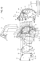
- FIG. 9 is an exploded perspective view of the electric components, components that house the electric components, and the like viewed from obliquely forward outside
- FIG. 10 is an exploded perspective view of the electric components, the components that house the electric components, and the like viewed from obliquely forward inside.
- the door latch device 10 includes a circuit board 120 that controls the motor 94.
- the number of motors controlled by the circuit board 120 may be plural.
- a recessed part 122 is formed in a region corresponding to a back side of the electric component region 42.
- An outer surface of the recessed part 122 is covered by the second cover 24 described above to form a second housing space 124.
- the circuit board 120 is housed in the second housing space 124.
- the first housing space 36 is partitioned into the mechanism region 40 in which the machine mechanism 38 is disposed, and the electric component region 42 as a remaining region thereof.
- the second housing space 124 is disposed on the back side of the electric component region 42 across the case 20. Due to this, the electric components and the like are disposed in a concentrated manner, and a conductive material can be shortened.
- the electric component region 42 occupies the forward upper part as described above, so that the circuit board 120 disposed on the recessed part 122 of the second housing space 124 is also disposed on the forward upper part based on orientation of the vehicle.
- the striker entry groove 14 into which waterdrops may penetrate is disposed rearward, so that waterdrops are prevented from reaching the second housing space 124 and the circuit board 120 therein.
- An external waterproof seal 126 is disposed between an edge of the recessed part 122 and the second cover 24 in the case 20, and the second housing space 124 is waterproofed against the outside.
- the external waterproof seal 126 is obtained by cutting a string-like sealing material by a predetermined length, and a dedicated molding is not required.
- the external waterproof seal 126 is disposed such that lower ends thereof are slightly overlapped with each other.
- the circuit board 120 includes pins 128, 130, 132, 134, and 136 (hereinafter, also representatively referred to as pins P) erected toward the outside, pin holders 138, 140, 142, 144, and 146 (hereinafter, also representatively referred to as pin holders H) supporting the pins with respect to the circuit board 120 by covering the periphery of bases of the pins P, and two positioning holes 147a and 147b.
- the pin holder H has appropriate strength, and can presses an internal waterproof seal B (described later).
- the pin holder H has appropriate elasticity, and exhibits sealing action for the pin P to be inserted.
- the pin holder H is made of resin, for example, a molding made of polyacetal.
- the two pins 128 are connected to the motor 94.
- the three pins 130 are connected to the first lock position switch 106 and the second lock position switch 108.
- the three pins 132 are connected to the key lever position switch 104.
- the two pins 134 are connected to the latch position switch 102 via the terminals 110a and 110b.
- the several pins 136 project inward from a hole of a terminal wall 30a of the first cover 22 to be part of the coupler 30.
- the coupler 30 includes the terminal wall 30a disposed on the first cover 22, and the pins 136 that are erected from the circuit board 120, pass through a pin hole 156 (described later), and project from the hole of the terminal wall 30a.
- the pin P is soldered on a back surface of the circuit board 120.
- the pin holder 138 holds the two pins 128, the pin holder 140 holds the three pins 130 in series, the pin holder 142 holds the three pins 132 in series, the pin holder 144 holds the two pins 134, and the pin holder 146 holds the several pins 136 in two columns.
- the positioning hole 147a and the positioning hole 147b are disposed at positions distant from each other.
- the positioning hole 147a is a round hole
- the positioning hole 147b is a long hole directed to the positioning hole 147a, and a manufacturing error of positioning pins 167a and 167b (described later) is allowed.
- the circuit board 120 further includes a CPU, a memory, resistance, a capacitor, and the like (not illustrated).
- the circuit board 120 has an irregular shape substantially along the second housing space 124.
- Pin holes 148, 150, 152, 154, and 156 are formed on a bottom plate 122b of the recessed part 122 in the case 20.
- the pin hole A establishes communication between the first housing space 36 and the second housing space 124.
- the pins 128, 130, 132, 134, and 136 respectively project from the pin holes 148, 150, 152, 154, and 156 in order toward the first housing space 36, and are inserted into pin connection holes disposed on the respective electric components to be electrically connected.
- Each of the electric components is held by a holding wall 165 disposed on the outer surface of the case 20.
- internal waterproof seals B are disposed in order.
- the internal waterproof seal B waterproofs a space between the first housing space 36 and the second housing space 124.
- the second housing space 124 is waterproofed by the external waterproof seal 126 and the internal waterproof seal B, and suitable for housing the circuit board 120.
- the internal waterproof seal B preferably has a rectangular ring shape corresponding to the corresponding pin hole A, but parts of a non-ringshaped body may be overlapped to be used like the external waterproof seal 126 depending on a condition.
- the circuit board 120 is disposed on an upper part than the striker entry groove 14 (refer to FIG. 3 ). Specifically, a lower part of the circuit board 120 has a horizontal linear shape, and this portion is disposed on an upper part than an upper end of the striker entry groove 14. Even if the external waterproof seal 126 and the internal waterproof seal B are not disposed, waterdrops entered through the striker entry groove 14 are prevented from reaching the circuit board 120.
- Two positioning pins 167a and 167b, and a plurality of inner circuit board supporters (first circuit board supporters) 169 are further formed on the bottom plate 122b.
- the positioning pins 167a and 167b are inserted into the positioning holes 147a and 147b, and the circuit board 120 is positioned.
- the inner circuit board supporter 169 is disposed at a position along the periphery of the circuit board 120, and abuts on an inner surface of the circuit board 120.
- a seal groove 173 is formed along an outer circumference of a surrounding wall 122a surrounding the recessed part 122.
- the external waterproof seal 126 is disposed on the seal groove 173.
- An overlap groove 173a for causing lower ends of the external waterproof seal 126 to be overlapped and disposed is formed in the seal groove 173.
- Projection pairs 173b projecting from both sides in an opposed manner are formed at a plurality of points including a bending point in the seal groove 173.
- the projection pair 173b is a stopper for the external waterproof seal 126.
- a space between the recessed part 122 and the second cover 24 are entirely waterproofed by the external waterproof seal 126.
- Pairs of support projections 168, 170, 172, 174, and 176 are formed on an inner surface of the second cover 24.
- the support projections 168, 170, 172, 174, and 176 are disposed at positions opposed to the pin holders 138, 140, 142, 144, and 146 in order across the circuit board 120.
- the support projection C supports a back side of an abutting part of the pin holder H in the circuit board 120.
- the support projection C and a leg part Hd (described later) are disposed on both sides across the pin P in a longitudinal direction of the pin holder H.
- two positioning posts 177a and 177b On the inner surface of the second cover 24, two positioning posts 177a and 177b, a plurality of outer circuit board supporters (second circuit board supporters) 178, a seal pressing projection 180, and an osmosis membrane holder 182 are further formed.
- a round hole is formed on the positioning post 177a, and a long hole directed to the positioning post 177a is formed on the positioning post 177b.
- the positioning pins 167a and 167b passed through the positioning holes 147a and 147b are inserted into respective holes of the positioning posts 177a and 177b, and the second cover 24 is positioned.
- the outer circuit board supporter 178 is disposed at a position along the periphery of the circuit board 120 and a position opposed to the inner circuit board supporter 169 via the circuit board 120, and sandwiches and holds the circuit board 120 between itself and the inner circuit board supporter 169.
- the inner circuit board supporter 169 and the outer circuit board supporter 178 are disposed to be opposed to each other, and to have the same cross-sectional shape and the same orientation.
- the seal pressing projection 180 is a narrow projection having a substantially ring shape along the seal groove 173, and presses an outer surface of the external waterproof seal 126.
- the external waterproof seal 126 exhibits sealing action by being pressed to be sealed by the seal pressing projection 180.
- the osmosis membrane holder 182 is a cylindrical body projecting outward, and has a hole 182a at a distal end thereof.
- An osmosis membrane filter 184 is attached to the osmosis membrane holder 182 from inside.
- the osmosis membrane filter 184 can prevent passage of waterdrops and cause water vapor to pass through the hole 182a, and prevents the second housing space 124 from being caused to be in a high humidity state.
- the osmosis membrane holder 182 and the osmosis membrane filter 184 are disposed in a space under the circuit board 120 in the second housing space 124.
- the osmosis membrane holder 182 is disposed in a range surrounded by an abutting part of the external waterproof seal 126 on the second cover 24.
- a plurality of screw holes 186 are disposed on the periphery of the second cover 24, and when a screw 188 passed through the screw hole 186 is screwed to a screw post 190 disposed on the case 20, the second cover 24 is fixed to the case 20.
- a plurality of hooks 192 are disposed on the periphery of the first cover 22, and when the hook 192 engages with a pawl 194 disposed on the case 20, the first cover 22 is fixed to the case 20. After the first cover 22 and the second cover 24 are attached to the case 20, the waterproof cover 26 is attached thereto from above. With the waterproof cover 26, even if the external waterproof seal 126 and the internal waterproof seal B are not disposed, waterdrops from above can be fairly prevented from reaching the circuit board 120 within the second housing space 124 covered by the second cover 24.
- the first housing space 36 formed between the case 20 and the first cover 22 is not completely waterproofed, and has what is called a dripproof structure. This is because that the dripproof structure is sufficient for each component housed in the first housing space 36.
- the second housing space 124 has a waterproof structure due to the external waterproof seal 126 and the internal waterproof seal B because precision electronic component and the like are mounted on the circuit board 120.
- first lock position switch first position switch
- second lock position switch second position switch
- the three pins 130 described above are distinguished from each other as a first signal pin 130a, a second signal pin 130b, and a common pin 130c (refer to FIG. 13 ) hereinafter.
- each of the first signal pin 130a, the second signal pin 130b, and the common pin 130c is erected from the circuit board 120.
- the first switch 106 and the second switch 108 are stacked, so that the first signal pin 130a, the second signal pin 130b, and the common pin 130c are close to each other, and can be collectively disposed on the circuit board 120, which is preferable on a print pattern layout.
- These pins may have a form such that, for example, an end part of a member such as the terminals 110a and 110b (refer to FIG. 3 ) is erected from the plate 112 or the housing.
- first lock position switch 106 and the second lock position switch 108 are simply referred to as the first switch 106 and the second switch 108.
- first switch 106 and the second switch 108 are stacked and disposed at positions shifted from each other in the X-direction (refer to FIG. 15 ).
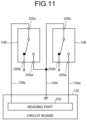
- FIG. 11 is a circuit diagram of the door latch device 10 to which the first switch 106 and the second switch 108 are applied.
- the first switch 106 and the second switch 108 have the same structure, and each include a first contact hole 200a connected to a normally open contact, a second contact hole 200b connected to a normally closed contact (that is, a reverse format of the first contact hole 200a), and a common contact hole 200c connected to a common contact.
- the first signal pin 130a is inserted into the first contact hole 200a of the first switch 106 to be electrically conducted (refer to FIG. 14 ).
- the second signal pin 130b is inserted into the common contact hole 200c of the second switch 108 to be electrically conducted (refer to FIG. 14 ).
- the common pin 130c is inserted into the common contact hole 200c of the first switch 106 and the first contact hole 200a of the second switch 108 to be electrically conducted (refer to FIG. 14 ).
- Three pins, that is, the first signal pin 130a, the second signal pin 130b, and the common pin 130c are enough for the pins P related to the first switch 106 and the second switch 108. In this case, the second contact hole 200b is not used in any of the first switch 106 and the second switch 108.
- Each of the first signal pin 130a, the second signal pin 130b, and the common pin 130c is soldered to the circuit board 120.
- Signals related to the first signal pin 130a and the second signal pin 130b are independently read by a reading part 202 on the circuit board 120.
- the signals read by the reading part 202 are supplied to a CPU (not illustrated), and used for control determination.
- the first switch 106 and the second switch 108 perform a switch operation at the same timing due to an operation of the sub-lock lever 82 as the operation detection target.
- the reading part 202 can acquire an operation detection signal of the sub-lock lever 82 twice, and even in a case in which any one of the first switch 106 and the second switch 108 breaks down, control processing can be continued based on a detection signal obtained by the other of the first switch 106 and the second switch 108 in a normal state.
- the CPU that performs control monitors the detection signal of the first switch 106 and the detection signal of the second switch 108, and if any one of the detection signals is changed, control processing based on the detection signal may be performed.
- the detection signal of the first switch 106 is not synchronized with the detection signal of the second switch 108, it may be determined that one of the first switch 106 and the second switch 108 the detection signal of which is not changed breaks down, and some kind of warning processing may be performed.
- FIG. 12 is a perspective view of the first switch 106.
- the second switch 108 also has the same structure.
- the first switch 106 has a slightly flat box shape along the XY-plane formed by the X-direction and the Y-direction orthogonal to each other, and a dimension in the Z-direction orthogonal to the X- and Y-directions is slightly small. In this case, the Z-direction is an inward/outward direction.
- the first switch 106 includes the first contact hole 200a, the second contact hole 200b, and the common contact hole 200c described above, and further includes an actuator 204 and positioning holes 206a and 206b.
- the first contact hole 200a, the second contact hole 200b, and the common contact hole 200c are disposed side by side in the X-direction, pass through the first switch 106 in the Z-direction, and open on a bottom part of a recessed part 208.
- a surface opposite to a surface on which the actuator 204 is disposed has a stepped shape in which an upper stage part 210a and a lower stage part 210b project.
- the positioning holes 206a and 206b pass through the upper stage part 210a and the lower stage part 210b in the Z-direction.
- the positioning holes 206a and 206b are disposed in the vicinity of both ends in the X-direction.
- the actuator 204 is disposed on a surface of a main body part, and moves forward and backward in the Y-direction. At the time when the first switch 106 does not act, the actuator 204 is in a projecting state, the first contact hole 200a and the common contact hole 200c are opened, and the second contact hole 200b and the common contact hole 200c are closed. When the actuator 204 is pushed against elastic force by external force, the first switch 106 is caused to be in an acting state, the first contact hole 200a and the common contact hole 200c are closed, and the second contact hole 200b and the common contact hole 200c are opened.
- FIG. 13 is an exploded perspective view of the first switch 106, the second switch 108, and the case 20.
- the case 20 in a range illustrated in FIG. 13 corresponds to the bottom plate 122b described above, that is, a portion at which the pin hole 150 is disposed and the periphery thereof.
- holding walls 165a, 165b, 165c, 165d, and 165e, mounts 212a, 212b, 212c, and 212d, and positioning pins 214a, 214b, and 214c are disposed in the case 20.
- the mounts 212a and 212b are low bulging parts on which the second switch 108 is placed.
- the mount 212a is disposed on one side in the Y-direction (Y1-direction in FIG. 13 ), and the mount 212b is disposed on the other side (Y2-direction in FIG. 13 ) across the pin hole 150.
- the mount 212a is formed in the X-direction while being in contact with the pin hole 150.
- the mount 212b has a "U" shape.
- the mount 212a and the mount 212b support substantially the entire circumference of a lower surface of the second switch 108.
- the mounts 212c and 212d are slightly high bulging parts on which the first switch 106 is placed.
- the mount 212c is disposed in the Y1-direction, and the mount 212d is disposed in the Y2-direction across the pin hole 150.
- the mount 212c is formed to be in contact with the pin hole 150.
- the mount 212d has a "U" shape.
- the mount 212c and the mount 212d support a substantially half of a lower surface of the first switch 106 in the X-direction (X1-direction in FIG. 13 ).
- the mount 212c and the mount 212d are disposed on the Xl-direction side as compared with the mount 212a and the mount 212b, and a dimension in the X-direction is substantially half of the mount 212a and the mount 212b, respectively. Dimensional differences in the Z-direction between the mount 212c and the mount 212a, and between the mount 212d and the mount 212b are equal to a dimension in the Z-direction of the second switch 108.
- the holding wall 165a is a slightly high bulging part supporting part of Y1-direction surfaces of the first switch 106 and the second switch 108, and disposed on the Y1-direction side as compared with the mount 212a.
- the holding wall 165b is a bulging part supporting part of a Y2-direction surface of the second switch 108, and connected with the mount 212d.
- the holding wall 165c is a bulging part supporting an Xl-direction surface of the second switch 108.
- the holding wall 165c also serves as part of the mount 212d.
- the holding wall 165d is a bulging part supporting part of a Y2-direction surface of the first switch 106, and erected from an inner side of the mount 212d.
- the holding wall 165d is integrated with the holding wall 165b.
- the holding wall 165e is a bulging part supporting an Xl-direction surface of the first switch 106, and erected from an inner surface of the
- the positioning pin 214a is inserted into the positioning hole 206a of the first switch 106.
- the positioning pin 214a is erected from an inner surface of the mount 212c.
- the positioning pin 214b is inserted into the positioning hole 206a of the second switch 108.
- the positioning pin 214c is inserted into the positioning hole 206b of the second switch 108.
- the positioning pins 214b and 214c are erected from an inner surface of the mount 212a.
- FIG. 14 is a partial cross-sectional side view of the first switch 106 and the second switch 108 in a state of being stacked and assembled, and the periphery thereof.
- FIG. 14 illustrates the first switch 106 and the second switch 108 viewed from the Y1-direction (refer to FIG. 13 ), and the holding walls 165a to 165e and the like are not illustrated.
- the first switch 106 and the second switch 108 are stacked in the Z-direction without a gap.
- the first switch 106 and the second switch 108 are disposed to be shifted from each other in the X-direction. Specifically, the first switch 106 is shifted in the Xl-direction with respect to the second switch 108, the common contact hole 200c of the first switch 106 is matched with the first contact hole 200a of the second switch 108 in the X-direction, and the common pin 130c is inserted through the common contact hole 200c and the first contact hole 200a to make continuity therebetween.
- a substantially half on a distal end side of the first signal pin 130a is inserted into the first contact hole 200a of the first switch 106, and a substantially half on a base side thereof is exposed.
- a substantially half on a base side of the second signal pin 130b is inserted into the common contact hole 200c of the second switch 108, and a substantially half on a distal end side thereof is exposed.
- the first switch 106 and the second switch 108 are not shifted from each other in the Y-direction (refer to FIG. 13 ) .
- Two slightly low projections 216a and 216b, and one slightly high projection 216c are disposed side by side in the X-direction on the first cover 22.
- An inner surface of the first switch 106 is held by the projections 216a and 216b, and an outer surface thereof is held by the mounts 212c and 212d, and the second switch 108.
- An inner surface of the second switch 108 is held by the first switch 106 and the projection 216c, and an outer surface thereof is held by the mounts 212a and 212b.
- Waterproof treatment is performed on the second housing space 124 as a region in which the circuit board 120 is disposed with the internal waterproof seal 160 around the pin hole 150 with respect to the first housing space 36 as a region in which the first switch 106 and the second switch 108 are disposed.
- the circuit board 120 is sandwiched and held to be stable by the pin holder 140 and the support projection 170.
- the bottom plate 122b serves as a partition plate that partitions between the first housing space 36 and the second housing space 124.
- FIG. 15 is a perspective view illustrating the first switch 106, the second switch 108, and the periphery thereof inside the door latch device 10.
- FIG. 15 corresponds to an upper portion of FIG. 3 .
- each actuator 204 of the first switch 106 and the second switch 108 projects from the main body part in the Y2-direction.
- the shaft part 82a of the sub-lock lever 82 is present at a position in the Y2-direction from a substantial center of two actuators 204.
- the shaft part 82a is a shaft in the Z-direction.
- the arm 98 projecting from the shaft part 82a is disposed on an upper part of the sub-lock lever 82.
- a first cam 98a and a second cam 98b are disposed at a distal end of the arm 98.
- the first cam 98a and the second cam 98b are shifted from each other in the Z-direction, the first cam 98a is disposed on an inner side, and the second cam 98b is disposed on an outer side.
- the first cam 98a and the actuator 204 of the first switch 106 are at the same position with respect to the Z-direction.
- the second cam 98b and the actuator 204 of the second switch 108 are at the same position with respect to the Z-direction.
- the first cam 98a and the second cam 98b are disposed to be shifted from each other in a circumferential direction with respect to the shaft part 82a.
- the arm 98 is appropriately long, so that a shift between the first cam 98a and the second cam 98b in the circumferential direction can be regarded as a shift on a substantially straight line, and is equal to a shift between the two actuators 204 in the X-direction.
- the first switch 106 and the second switch 108 are stacked, and a shift amount between the two actuators 204 in the X-direction is small, so that a shift amount between the first cam 98a and the second cam 98b is also small.
- the arm 98 can be set to be relatively narrow.
- FIG. 16 is a diagram illustrating an operational relation among the first switch 106, the second switch 108, and a sub-lock lever 82, (a) is a diagram illustrating the sub-lock lever 82 in a state of a locked attitude, and (b) is a diagram illustrating the sub-lock lever 82 in a state of an unlocked attitude.
- each of the first switch 106 and the second switch 108 is in a non-acting state, and is in the state illustrated in FIG. 11 . That is, each first contact hole 200a is opened with respect to the common contact hole 200c.
- the reading part 202 reads that each first contact hole 200a is opened with respect to the common contact hole 200c from the first signal pin 130a and the second signal pin 130b.
- the first cam 98a and the second cam 98b are displaced from the state illustrated in FIG. 16(a) in a substantial X2-direction (reverse direction of X1) following the rotation of the sub-lock lever 82.
- the first cam 98a pushes the actuator 204 of the first switch 106 in the Y2-direction
- the second cam 98b pushes the actuator 204 of the second switch 108 in the Y2-direction.
- each first contact hole 200a (refer to FIG. 11 ) is closed with respect to the common contact hole 200c.
- the reading part 202 reads that each first contact hole 200a is closed with respect to the common contact hole 200c from the first signal pin 130a and the second signal pin 130b.
- the reading part 202 reads the attitude of the sub-lock lever 82 twice, so that the operation thereof can be detected more securely.
- first switch 106 and the second switch 108 Even if any one of the first switch 106 and the second switch 108 breaks down and does not perform the switch operation, predetermined control can be performed based on the switch operation of the other one thereof in a normal state. Additionally, the first switch 106 and the second switch 108 are stacked, so that an occupied area is small.
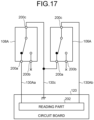
- FIG. 17 is a circuit diagram according to a modification to which a second switch 106A and a first switch 108A are applied in place of the first switch 106 and the second switch 108 described above.
- the former is a normally open circuit
- the latter is a normally closed circuit.
- the first contact hole 200a is a normally open contact and the second contact hole 200b is a normally closed contact.
- the first contact hole 200a is the normally closed contact and the second contact hole 200b is the normally open contact.
- the other configurations of the first switch 108A and the second switch 106A are the same as those of the first switch 106 and the second switch 108.
- a first signal pin 130Aa in FIG. 17 is the same as the second signal pin 130b in FIG. 11
- a second signal pin 130Ab is the same as the first signal pin 130a in FIG. 11 , and only designations thereof are different.
- the first signal pin 130Aa is inserted into the first contact hole 200a of the first switch 108A to be electrically conducted.
- the second signal pin 130Ab is inserted into the common contact hole 200c of the second switch 106A to be electrically conducted.
- the common pin 130c is inserted into the common contact hole 200c of the first switch 108A and the first contact hole 200a of the second switch 106A to be electrically conducted.
- the second contact hole 200b is not used in any of the first switch 108A and the second switch 106A.
- each of the first switch 108A and the second switch 106A is in the non-acting state, and each first contact hole 200a is closed with respect to the common contact hole 200c.
- the reading part 202 reads that each first contact hole 200a is closed with respect to the common contact hole 200c from the first signal pin 130Aa and the second signal pin 130Ab.
- each of the first switch 108A and the second switch 106A is in the acting state. That is, each first contact hole 200a is opened with respect to the common contact hole 200c.
- the reading part 202 reads that each first contact hole 200a is open with respect to the common contact hole 200c from the first signal pin 130Aa and the second signal pin 130Ab.
- the reading part 202 can detect the attitude of the sub-lock lever 82 twice.
Landscapes
- Lock And Its Accessories (AREA)
Claims (6)
- Türverriegelungsvorrichtung (10), umfassend:einen ersten Positionsschalter (106) und einen zweiten Positionsschalter (108), wobei jeder des ersten Positionsschalters (106) und des zweiten Positionsschalters (108) einschließtein erstes Kontaktloch (200a), das entweder mit einem normal offenen Kontakt oder mit einem normal geschlossenen Kontakt verbunden ist,ein zweites Kontaktloch (200b), das mit einem Kontakt verbunden ist, der ein umgekehrtes Format des ersten Kontaktlochs (200a) aufweist, undein gemeinsames Kontaktloch (200c), das mit einem gemeinsamen Kontakt verbunden ist, wobeidas erste Kontaktloch (200a), das zweite Kontaktloch (200b) und das gemeinsame Kontaktloch (200c) auf einer geraden Linie angeordnet sind,der erste Positionsschalter (106) und der zweite Positionsschalter (108) an entlang der geraden Linie gegeneinander verschobenen Positionen angeordnet sind und in einer Durchdringungsrichtung des ersten Kontaktlochs (200a), des zweiten Kontaktlochs (200b) und des gemeinsamen Kontakts gestapelt sind;dadurch gekennzeichnet, dass die Türverriegelungsvorrichtung (10) weiter umfasst:einen gemeinsamen Stift (130c), der konfiguriert ist, um elektrisch zu dem gemeinsamen Kontaktloch (200c) des ersten Positionsschalters (106) und dem ersten Kontaktloch (200a) des zweiten Positionsschalters (108) geleitet zu werden, indem er darin eingeführt wird;einen ersten Signalstift (130a), der konfiguriert ist, um elektrisch zu dem ersten Kontaktloch (200a) des ersten Positionsschalters (106) geleitet zu werden, indem er darin eingeführt wird; undeinen zweiten Signalstift (130b), der konfiguriert ist, um elektrisch zu dem gemeinsamen Kontakt des zweiten Positionsschalters (108) geleitet zu werden, indem er darin eingeführt wird, undder erste Positionsschalter (106) und der zweite Positionsschalter (108) konfiguriert sind, um einen Schaltvorgang zu einem gleichen Zeitpunkt eines Vorgangs eines vorbestimmten Vorgangserkennungsziels (82) durchzuführen.
- Türverriegelungsvorrichtung (10) nach Anspruch 1, weiter umfassend eine Leiterplatte (120) wobei
der gemeinsame Stift (130c), der erste Signalstift (130a) und der zweite Signalstift (130b) jeweils auf der Leiterplatte (120) aufgerichtet sind. - Türverriegelungsvorrichtung nach Anspruch 2, wobeiein Raum (124), in dem die Leiterplatte (120) angeordnet ist, und ein Raum (36), in dem der erste Positionsschalter (106) und der zweite Positionsschalter (108) angeordnet sind, mit einer Trennplatte (122b) unterteilt sind, undder erste Signalstift (130a), der zweite Signalstift (130b) und der gemeinsame Stift (130c) konfiguriert sind, um Stiftlöcher (148, 150, 152, 154, 156), die auf der Trennplatte (122b) ausgebildet sind, zu durchdringen und von einem der Räume zu einem anderen der Räume vorzustehen.
- Türverriegelungsvorrichtung (10) nach Anspruch 3, wobei in dem Raum (124), in dem die Leiterplatte (120) angeordnet ist, eine wasserabweisende Behandlung auf den Raum (36), in dem der erste Positionsschalter (106) und der zweite Positionsschalter (108) angeordnet sind, um die Stiftlöcher (148, 150, 152, 154, 156) herum angewendet wird.
- Türverriegelungsvorrichtung (10) nach Anspruch 1 oder 2, wobeidas Vorgangserkennungsziel (82) einschließteinen ersten Nocken (98a), der konfiguriert ist, um auf ein Betätigungselement des ersten Positionsschalters (106) zu wirken, undeinen zweiten Nocken (98b), der konfiguriert ist, um auf ein Betätigungselement des zweiten Positionsschalters (108) zu wirken, undder erste Nocken (98a) und der zweite Nocken (98b) in einer Stapelrichtung des ersten Positionsschalters (106) und des zweiten Positionsschalters (108) voneinander verschoben sind und an entlang der geraden Linie voneinander verschobenen Positionen angeordnet sind.
- Türverriegelungsvorrichtung (10) nach einem der Ansprüche 1 bis 5, umfassend:einen Verriegelungsmechanismus (44), der konfiguriert ist, um eine Tür eines Fahrzeugs in einem geschlossenen Zustand zu halten;eine elektrische Löseeinheit (84), die konfiguriert ist, um den Verriegelungsmechanismus (44) durch die Kraft eines Motors (94) zu lösen;eine Handlöseeinheit (34, 59), die konfiguriert ist, um den Verriegelungsmechanismus (44) durch manuelle Betätigungskraft zu lösen; undeinen Verriegelungsmechanismus (46), der konfiguriert ist, um zwischen einem verriegelten Zustand zum Sperren einer Funktion der Handlöseeinheit (34, 59) und einem entriegelten Zustand zum Aktivieren derselben umzuschalten, wobeidas Vorgangserkennungsziel (82) ein Bauteil ist, dessen Position in Abhängigkeit davon geschaltet wird, ob sich der Verriegelungsmechanismus (46) im verriegelten Zustand oder im entriegelten Zustand befindet, undder erste Positionsschalter (106) und der zweite Positionsschalter (108) konfiguriert sind, um zu erkennen, ob sich das Vorgangserkennungsziel (82) im verriegelten Zustand oder im entriegelten Zustand befindet.
Applications Claiming Priority (2)
| Application Number | Priority Date | Filing Date | Title |
|---|---|---|---|
| JP2019141668A JP7055953B2 (ja) | 2019-07-31 | 2019-07-31 | ドアラッチ装置 |
| PCT/JP2019/041980 WO2021019798A1 (ja) | 2019-07-31 | 2019-10-25 | ドアラッチ装置 |
Publications (3)
| Publication Number | Publication Date |
|---|---|
| EP4006274A1 EP4006274A1 (de) | 2022-06-01 |
| EP4006274A4 EP4006274A4 (de) | 2023-08-30 |
| EP4006274B1 true EP4006274B1 (de) | 2024-10-23 |
Family
ID=74229489
Family Applications (1)
| Application Number | Title | Priority Date | Filing Date |
|---|---|---|---|
| EP19939501.3A Active EP4006274B1 (de) | 2019-07-31 | 2019-10-25 | Türverriegelungsvorrichtung |
Country Status (5)
| Country | Link |
|---|---|
| US (1) | US12071792B2 (de) |
| EP (1) | EP4006274B1 (de) |
| JP (1) | JP7055953B2 (de) |
| CN (1) | CN217106559U (de) |
| WO (1) | WO2021019798A1 (de) |
Families Citing this family (2)
| Publication number | Priority date | Publication date | Assignee | Title |
|---|---|---|---|---|
| DE102020124698A1 (de) * | 2020-09-22 | 2022-03-24 | Brose Schließsysteme GmbH & Co. Kommanditgesellschaft | Kraftfahrzeugschloss |
| KR20240077929A (ko) * | 2022-11-25 | 2024-06-03 | 현대자동차주식회사 | 래치기구의 개폐 감지시스템 |
Citations (1)
| Publication number | Priority date | Publication date | Assignee | Title |
|---|---|---|---|---|
| EP1869274A1 (de) * | 2005-03-23 | 2007-12-26 | Magna Closures Inc. | Globales seitentürschloss |
Family Cites Families (18)
| Publication number | Priority date | Publication date | Assignee | Title |
|---|---|---|---|---|
| JPS57163315A (en) | 1981-04-01 | 1982-10-07 | Nitsukan Kourai Ninjin Kk | Preventing agent and remedy for thrombosis |
| DE4222018C1 (en) * | 1992-07-04 | 1993-06-17 | Kiekert Gmbh & Co Kg, 5628 Heiligenhaus, De | Electric locking mechanism for automobile door - has locking and unlocking signals provided by switch elements cooperating with cam path of rotary cam carrier |
| DE19632995C2 (de) * | 1996-08-16 | 2000-08-24 | Kiekert Ag | Kraftfahrzeugtürverschluß mit einer Mehrzahl von Schaltern und einem Schalterbetätigungssystem |
| EP0960246B1 (de) * | 1997-02-04 | 2005-08-31 | Intier Automotive Closures Inc. | Kraftfahrzeug-türschliesssystem mit getrennten motorangetriebenen türinnen- und türaussenverriegelungsvorrichtungen |
| EP0982978B1 (de) * | 1998-08-25 | 2005-05-25 | Kiekert Aktiengesellschaft | Gehäuse, insbesondere Schlossgehäuse mit elektrischen Anschlusseinrichtungen |
| DE102008015627A1 (de) * | 2008-03-26 | 2009-10-01 | Kiekert Ag | Komponententräger für elektrische/elektronische Bauteile sowie zugehöriges Herstellungsverfahren |
| JP4953481B2 (ja) | 2010-03-09 | 2012-06-13 | 三井金属アクト株式会社 | 車両用ドアラッチ装置及び該ドアラッチ装置を備えている車両用ドア |
| DE102012003743A1 (de) | 2012-02-28 | 2013-08-29 | Kiekert Aktiengesellschaft | Kraftfahrzeugtürverschluss |
| KR101356996B1 (ko) * | 2012-12-18 | 2014-02-05 | 주식회사 리한도어 | 도어래치용 스위치 회로 유닛 |
| DE102013211827A1 (de) * | 2013-06-21 | 2014-12-24 | Zf Friedrichshafen Ag | Schalter, Verfahren zum Herstellen eines Schalters und Elektronikmodulsystem |
| CH710637A2 (de) * | 2015-01-19 | 2016-07-29 | MSL Schloss- und Beschlägefabrik AG | Drückersperrschloss mit motorischer Fallenfreischaltung. |
| CA2976410C (en) | 2015-02-12 | 2020-06-16 | Gecom Corporation | Vehicle door latch device |
| BR112017019381A2 (pt) * | 2015-03-10 | 2018-04-24 | Gecom Corporation | ?dispositivo de trava de porta? |
| US10392838B2 (en) | 2015-06-11 | 2019-08-27 | Magna Closures Inc. | Key cylinder release mechanism for vehicle closure latches, latch assembly therewith and method of mechanically releasing a vehicle closure latch |
| JP6613506B2 (ja) * | 2016-03-16 | 2019-12-04 | 三井金属アクト株式会社 | 車両用ドア開閉装置 |
| JP6711716B2 (ja) | 2016-07-20 | 2020-06-17 | 三井金属アクト株式会社 | 車両ドアラッチ装置 |
| JP6703271B2 (ja) | 2016-09-21 | 2020-06-03 | 株式会社アンセイ | 車両用ドアロック装置 |
| JP2020045653A (ja) * | 2018-09-18 | 2020-03-26 | アイシン精機株式会社 | 車両用ドアロック装置 |
-
2019
- 2019-07-31 JP JP2019141668A patent/JP7055953B2/ja active Active
- 2019-10-25 EP EP19939501.3A patent/EP4006274B1/de active Active
- 2019-10-25 WO PCT/JP2019/041980 patent/WO2021019798A1/ja not_active Ceased
- 2019-10-25 US US17/618,813 patent/US12071792B2/en active Active
- 2019-10-25 CN CN201990001407.2U patent/CN217106559U/zh active Active
Patent Citations (2)
| Publication number | Priority date | Publication date | Assignee | Title |
|---|---|---|---|---|
| EP1869274A1 (de) * | 2005-03-23 | 2007-12-26 | Magna Closures Inc. | Globales seitentürschloss |
| EP1869274B1 (de) * | 2005-03-23 | 2011-01-26 | Magna Closures Inc. | Globales seitentürschloss |
Also Published As
| Publication number | Publication date |
|---|---|
| US12071792B2 (en) | 2024-08-27 |
| JP2021025236A (ja) | 2021-02-22 |
| EP4006274A1 (de) | 2022-06-01 |
| US20220235588A1 (en) | 2022-07-28 |
| CN217106559U (zh) | 2022-08-02 |
| EP4006274A4 (de) | 2023-08-30 |
| WO2021019798A1 (ja) | 2021-02-04 |
| JP7055953B2 (ja) | 2022-04-19 |
Similar Documents
| Publication | Publication Date | Title |
|---|---|---|
| EP4006273B1 (de) | Türverriegelungsvorrichtung | |
| US7810853B2 (en) | Vehicle door lock | |
| EP4006274B1 (de) | Türverriegelungsvorrichtung | |
| US12442226B2 (en) | Door latch device | |
| US10458157B2 (en) | Vehicle door lock device | |
| EP3992402B1 (de) | Türverriegelungsvorrichtung | |
| EP3257693B1 (de) | Türverriegelungsvorrichtung | |
| EP4083357B1 (de) | Türverriegelungsvorrichtung | |
| JP2020045653A (ja) | 車両用ドアロック装置 | |
| CN108868390B (zh) | 车辆用锁定装置 | |
| ES2802284B2 (es) | Periferico para la instalacion de un sistema de alarma | |
| JP7271849B2 (ja) | ドアラッチ装置 | |
| JP4110901B2 (ja) | ドア開閉操作装置 | |
| JP2017021929A (ja) | 充電ケーブルロック装置 | |
| JP2006266027A (ja) | 車両用ドアロック装置 | |
| JP2021067150A (ja) | ドアラッチ装置 |
Legal Events
| Date | Code | Title | Description |
|---|---|---|---|
| STAA | Information on the status of an ep patent application or granted ep patent |
Free format text: STATUS: THE INTERNATIONAL PUBLICATION HAS BEEN MADE |
|
| PUAI | Public reference made under article 153(3) epc to a published international application that has entered the european phase |
Free format text: ORIGINAL CODE: 0009012 |
|
| STAA | Information on the status of an ep patent application or granted ep patent |
Free format text: STATUS: REQUEST FOR EXAMINATION WAS MADE |
|
| 17P | Request for examination filed |
Effective date: 20220111 |
|
| AK | Designated contracting states |
Kind code of ref document: A1 Designated state(s): AL AT BE BG CH CY CZ DE DK EE ES FI FR GB GR HR HU IE IS IT LI LT LU LV MC MK MT NL NO PL PT RO RS SE SI SK SM TR |
|
| DAV | Request for validation of the european patent (deleted) | ||
| DAX | Request for extension of the european patent (deleted) | ||
| A4 | Supplementary search report drawn up and despatched |
Effective date: 20230727 |
|
| RIC1 | Information provided on ipc code assigned before grant |
Ipc: H01H 13/50 20060101ALI20230721BHEP Ipc: E05B 81/72 20140101ALI20230721BHEP Ipc: E05B 81/64 20140101ALI20230721BHEP Ipc: E05B 81/06 20140101ALI20230721BHEP Ipc: E05B 81/74 20140101AFI20230721BHEP |
|
| GRAP | Despatch of communication of intention to grant a patent |
Free format text: ORIGINAL CODE: EPIDOSNIGR1 |
|
| STAA | Information on the status of an ep patent application or granted ep patent |
Free format text: STATUS: GRANT OF PATENT IS INTENDED |
|
| INTG | Intention to grant announced |
Effective date: 20240628 |
|
| GRAS | Grant fee paid |
Free format text: ORIGINAL CODE: EPIDOSNIGR3 |
|
| GRAA | (expected) grant |
Free format text: ORIGINAL CODE: 0009210 |
|
| STAA | Information on the status of an ep patent application or granted ep patent |
Free format text: STATUS: THE PATENT HAS BEEN GRANTED |
|
| AK | Designated contracting states |
Kind code of ref document: B1 Designated state(s): AL AT BE BG CH CY CZ DE DK EE ES FI FR GB GR HR HU IE IS IT LI LT LU LV MC MK MT NL NO PL PT RO RS SE SI SK SM TR |
|
| REG | Reference to a national code |
Ref country code: GB Ref legal event code: FG4D |
|
| REG | Reference to a national code |
Ref country code: CH Ref legal event code: EP |
|
| REG | Reference to a national code |
Ref country code: DE Ref legal event code: R096 Ref document number: 602019060988 Country of ref document: DE |
|
| REG | Reference to a national code |
Ref country code: IE Ref legal event code: FG4D |
|
| REG | Reference to a national code |
Ref country code: LT Ref legal event code: MG9D |
|
| REG | Reference to a national code |
Ref country code: NL Ref legal event code: MP Effective date: 20241023 |
|
| REG | Reference to a national code |
Ref country code: AT Ref legal event code: MK05 Ref document number: 1734965 Country of ref document: AT Kind code of ref document: T Effective date: 20241023 |
|
| PG25 | Lapsed in a contracting state [announced via postgrant information from national office to epo] |
Ref country code: NL Free format text: LAPSE BECAUSE OF FAILURE TO SUBMIT A TRANSLATION OF THE DESCRIPTION OR TO PAY THE FEE WITHIN THE PRESCRIBED TIME-LIMIT Effective date: 20241023 |
|
| PG25 | Lapsed in a contracting state [announced via postgrant information from national office to epo] |
Ref country code: NL Free format text: LAPSE BECAUSE OF FAILURE TO SUBMIT A TRANSLATION OF THE DESCRIPTION OR TO PAY THE FEE WITHIN THE PRESCRIBED TIME-LIMIT Effective date: 20241023 |
|
| PG25 | Lapsed in a contracting state [announced via postgrant information from national office to epo] |
Ref country code: PT Free format text: LAPSE BECAUSE OF FAILURE TO SUBMIT A TRANSLATION OF THE DESCRIPTION OR TO PAY THE FEE WITHIN THE PRESCRIBED TIME-LIMIT Effective date: 20250224 Ref country code: HR Free format text: LAPSE BECAUSE OF FAILURE TO SUBMIT A TRANSLATION OF THE DESCRIPTION OR TO PAY THE FEE WITHIN THE PRESCRIBED TIME-LIMIT Effective date: 20241023 Ref country code: IS Free format text: LAPSE BECAUSE OF FAILURE TO SUBMIT A TRANSLATION OF THE DESCRIPTION OR TO PAY THE FEE WITHIN THE PRESCRIBED TIME-LIMIT Effective date: 20250223 |
|
| PG25 | Lapsed in a contracting state [announced via postgrant information from national office to epo] |
Ref country code: FI Free format text: LAPSE BECAUSE OF FAILURE TO SUBMIT A TRANSLATION OF THE DESCRIPTION OR TO PAY THE FEE WITHIN THE PRESCRIBED TIME-LIMIT Effective date: 20241023 |
|
| PG25 | Lapsed in a contracting state [announced via postgrant information from national office to epo] |
Ref country code: BG Free format text: LAPSE BECAUSE OF FAILURE TO SUBMIT A TRANSLATION OF THE DESCRIPTION OR TO PAY THE FEE WITHIN THE PRESCRIBED TIME-LIMIT Effective date: 20241023 |
|
| PG25 | Lapsed in a contracting state [announced via postgrant information from national office to epo] |
Ref country code: ES Free format text: LAPSE BECAUSE OF FAILURE TO SUBMIT A TRANSLATION OF THE DESCRIPTION OR TO PAY THE FEE WITHIN THE PRESCRIBED TIME-LIMIT Effective date: 20241023 |
|
| PG25 | Lapsed in a contracting state [announced via postgrant information from national office to epo] |
Ref country code: NO Free format text: LAPSE BECAUSE OF FAILURE TO SUBMIT A TRANSLATION OF THE DESCRIPTION OR TO PAY THE FEE WITHIN THE PRESCRIBED TIME-LIMIT Effective date: 20250123 |
|
| PG25 | Lapsed in a contracting state [announced via postgrant information from national office to epo] |
Ref country code: LV Free format text: LAPSE BECAUSE OF FAILURE TO SUBMIT A TRANSLATION OF THE DESCRIPTION OR TO PAY THE FEE WITHIN THE PRESCRIBED TIME-LIMIT Effective date: 20241023 Ref country code: AT Free format text: LAPSE BECAUSE OF FAILURE TO SUBMIT A TRANSLATION OF THE DESCRIPTION OR TO PAY THE FEE WITHIN THE PRESCRIBED TIME-LIMIT Effective date: 20241023 Ref country code: GR Free format text: LAPSE BECAUSE OF FAILURE TO SUBMIT A TRANSLATION OF THE DESCRIPTION OR TO PAY THE FEE WITHIN THE PRESCRIBED TIME-LIMIT Effective date: 20250124 |
|
| PG25 | Lapsed in a contracting state [announced via postgrant information from national office to epo] |
Ref country code: PL Free format text: LAPSE BECAUSE OF FAILURE TO SUBMIT A TRANSLATION OF THE DESCRIPTION OR TO PAY THE FEE WITHIN THE PRESCRIBED TIME-LIMIT Effective date: 20241023 |
|
| PG25 | Lapsed in a contracting state [announced via postgrant information from national office to epo] |
Ref country code: RS Free format text: LAPSE BECAUSE OF FAILURE TO SUBMIT A TRANSLATION OF THE DESCRIPTION OR TO PAY THE FEE WITHIN THE PRESCRIBED TIME-LIMIT Effective date: 20250123 |
|
| REG | Reference to a national code |
Ref country code: CH Ref legal event code: PL |
|
| PG25 | Lapsed in a contracting state [announced via postgrant information from national office to epo] |
Ref country code: SM Free format text: LAPSE BECAUSE OF FAILURE TO SUBMIT A TRANSLATION OF THE DESCRIPTION OR TO PAY THE FEE WITHIN THE PRESCRIBED TIME-LIMIT Effective date: 20241023 |
|
| PG25 | Lapsed in a contracting state [announced via postgrant information from national office to epo] |
Ref country code: MC Free format text: LAPSE BECAUSE OF FAILURE TO SUBMIT A TRANSLATION OF THE DESCRIPTION OR TO PAY THE FEE WITHIN THE PRESCRIBED TIME-LIMIT Effective date: 20241023 |
|
| PG25 | Lapsed in a contracting state [announced via postgrant information from national office to epo] |
Ref country code: DK Free format text: LAPSE BECAUSE OF FAILURE TO SUBMIT A TRANSLATION OF THE DESCRIPTION OR TO PAY THE FEE WITHIN THE PRESCRIBED TIME-LIMIT Effective date: 20241023 |
|
| PG25 | Lapsed in a contracting state [announced via postgrant information from national office to epo] |
Ref country code: LU Free format text: LAPSE BECAUSE OF NON-PAYMENT OF DUE FEES Effective date: 20241025 Ref country code: BE Free format text: LAPSE BECAUSE OF NON-PAYMENT OF DUE FEES Effective date: 20241031 |
|
| PG25 | Lapsed in a contracting state [announced via postgrant information from national office to epo] |
Ref country code: EE Free format text: LAPSE BECAUSE OF FAILURE TO SUBMIT A TRANSLATION OF THE DESCRIPTION OR TO PAY THE FEE WITHIN THE PRESCRIBED TIME-LIMIT Effective date: 20241023 |
|
| PG25 | Lapsed in a contracting state [announced via postgrant information from national office to epo] |
Ref country code: CH Free format text: LAPSE BECAUSE OF NON-PAYMENT OF DUE FEES Effective date: 20241031 |
|
| PG25 | Lapsed in a contracting state [announced via postgrant information from national office to epo] |
Ref country code: RO Free format text: LAPSE BECAUSE OF FAILURE TO SUBMIT A TRANSLATION OF THE DESCRIPTION OR TO PAY THE FEE WITHIN THE PRESCRIBED TIME-LIMIT Effective date: 20241023 |
|
| REG | Reference to a national code |
Ref country code: DE Ref legal event code: R097 Ref document number: 602019060988 Country of ref document: DE |
|
| PG25 | Lapsed in a contracting state [announced via postgrant information from national office to epo] |
Ref country code: SK Free format text: LAPSE BECAUSE OF FAILURE TO SUBMIT A TRANSLATION OF THE DESCRIPTION OR TO PAY THE FEE WITHIN THE PRESCRIBED TIME-LIMIT Effective date: 20241023 |
|
| PG25 | Lapsed in a contracting state [announced via postgrant information from national office to epo] |
Ref country code: CZ Free format text: LAPSE BECAUSE OF FAILURE TO SUBMIT A TRANSLATION OF THE DESCRIPTION OR TO PAY THE FEE WITHIN THE PRESCRIBED TIME-LIMIT Effective date: 20241023 |
|
| PG25 | Lapsed in a contracting state [announced via postgrant information from national office to epo] |
Ref country code: IT Free format text: LAPSE BECAUSE OF FAILURE TO SUBMIT A TRANSLATION OF THE DESCRIPTION OR TO PAY THE FEE WITHIN THE PRESCRIBED TIME-LIMIT Effective date: 20241023 |
|
| REG | Reference to a national code |
Ref country code: BE Ref legal event code: MM Effective date: 20241031 |
|
| PLBE | No opposition filed within time limit |
Free format text: ORIGINAL CODE: 0009261 |
|
| STAA | Information on the status of an ep patent application or granted ep patent |
Free format text: STATUS: NO OPPOSITION FILED WITHIN TIME LIMIT |
|
| PG25 | Lapsed in a contracting state [announced via postgrant information from national office to epo] |
Ref country code: SE Free format text: LAPSE BECAUSE OF FAILURE TO SUBMIT A TRANSLATION OF THE DESCRIPTION OR TO PAY THE FEE WITHIN THE PRESCRIBED TIME-LIMIT Effective date: 20241023 |
|
| GBPC | Gb: european patent ceased through non-payment of renewal fee |
Effective date: 20250123 |
|
| 26N | No opposition filed |
Effective date: 20250724 |
|
| PG25 | Lapsed in a contracting state [announced via postgrant information from national office to epo] |
Ref country code: GB Free format text: LAPSE BECAUSE OF NON-PAYMENT OF DUE FEES Effective date: 20250123 |
|
| PG25 | Lapsed in a contracting state [announced via postgrant information from national office to epo] |
Ref country code: FR Free format text: LAPSE BECAUSE OF NON-PAYMENT OF DUE FEES Effective date: 20241223 |
|
| PG25 | Lapsed in a contracting state [announced via postgrant information from national office to epo] |
Ref country code: IE Free format text: LAPSE BECAUSE OF NON-PAYMENT OF DUE FEES Effective date: 20241025 |
|
| PGFP | Annual fee paid to national office [announced via postgrant information from national office to epo] |
Ref country code: DE Payment date: 20250902 Year of fee payment: 7 |
|
| PG25 | Lapsed in a contracting state [announced via postgrant information from national office to epo] |
Ref country code: CY Free format text: LAPSE BECAUSE OF FAILURE TO SUBMIT A TRANSLATION OF THE DESCRIPTION OR TO PAY THE FEE WITHIN THE PRESCRIBED TIME-LIMIT; INVALID AB INITIO Effective date: 20191025 |
|
| REG | Reference to a national code |
Ref country code: DE Ref legal event code: R081 Ref document number: 602019060988 Country of ref document: DE Owner name: HI-LEX ACT CORPORATION, YOKOHAMA-SHI, JP Free format text: FORMER OWNER: MITSUI KINZOKU ACT CORPORATION, YOKOHAMA-SHI, KANAGAWA, JP |
|
| PG25 | Lapsed in a contracting state [announced via postgrant information from national office to epo] |
Ref country code: HU Free format text: LAPSE BECAUSE OF FAILURE TO SUBMIT A TRANSLATION OF THE DESCRIPTION OR TO PAY THE FEE WITHIN THE PRESCRIBED TIME-LIMIT; INVALID AB INITIO Effective date: 20191025 |