EP4006277B1 - Dispositif pour contraindre l'ouverture de portes ou de fenêtres - Google Patents
Dispositif pour contraindre l'ouverture de portes ou de fenêtres Download PDFInfo
- Publication number
- EP4006277B1 EP4006277B1 EP21208397.6A EP21208397A EP4006277B1 EP 4006277 B1 EP4006277 B1 EP 4006277B1 EP 21208397 A EP21208397 A EP 21208397A EP 4006277 B1 EP4006277 B1 EP 4006277B1
- Authority
- EP
- European Patent Office
- Prior art keywords
- leaf
- latch
- slot
- guide body
- handle
- Prior art date
- Legal status (The legal status is an assumption and is not a legal conclusion. Google has not performed a legal analysis and makes no representation as to the accuracy of the status listed.)
- Active
Links
Images


Classifications
-
- E—FIXED CONSTRUCTIONS
- E05—LOCKS; KEYS; WINDOW OR DOOR FITTINGS; SAFES
- E05C—BOLTS OR FASTENING DEVICES FOR WINGS, SPECIALLY FOR DOORS OR WINDOWS
- E05C17/00—Devices for holding wings open; Devices for limiting opening of wings or for holding wings open by a movable member extending between frame and wing; Braking devices, stops or buffers, combined therewith
- E05C17/02—Devices for holding wings open; Devices for limiting opening of wings or for holding wings open by a movable member extending between frame and wing; Braking devices, stops or buffers, combined therewith by mechanical means
- E05C17/04—Devices for holding wings open; Devices for limiting opening of wings or for holding wings open by a movable member extending between frame and wing; Braking devices, stops or buffers, combined therewith by mechanical means with a movable bar or equivalent member extending between frame and wing
- E05C17/12—Devices for holding wings open; Devices for limiting opening of wings or for holding wings open by a movable member extending between frame and wing; Braking devices, stops or buffers, combined therewith by mechanical means with a movable bar or equivalent member extending between frame and wing consisting of a single rod
- E05C17/24—Devices for holding wings open; Devices for limiting opening of wings or for holding wings open by a movable member extending between frame and wing; Braking devices, stops or buffers, combined therewith by mechanical means with a movable bar or equivalent member extending between frame and wing consisting of a single rod pivoted at one end, and with the other end running along a guide member
- E05C17/28—Devices for holding wings open; Devices for limiting opening of wings or for holding wings open by a movable member extending between frame and wing; Braking devices, stops or buffers, combined therewith by mechanical means with a movable bar or equivalent member extending between frame and wing consisting of a single rod pivoted at one end, and with the other end running along a guide member with braking, clamping or securing means at the connection to the guide member
-
- E—FIXED CONSTRUCTIONS
- E05—LOCKS; KEYS; WINDOW OR DOOR FITTINGS; SAFES
- E05C—BOLTS OR FASTENING DEVICES FOR WINGS, SPECIALLY FOR DOORS OR WINDOWS
- E05C9/00—Arrangements of simultaneously actuated bolts or other securing devices at well-separated positions on the same wing
Definitions
- This invention relates to a device for constraining the opening of doors or windows, in particular for doors or windows with a traditional leaf-type opening.
- This type of door or window has:
- the operating means usually comprise drive rods slidably positioned in channels present on the perimeter profile of the frame and on which pins and/or bosses are associated.
- the movement of the rods allows the pins and/or bosses to move into contact with or away from the striker elements to obtain the closed or open configuration of the movable leaf.
- the door or window according to the invention comprises a selector device which is able to add an open configuration constraining the angle of opening of the leaf, as well as the traditional opening of the leaf.
- a prior art selector device of simplified type disclosed in EP 3 702 562 and EP 3 363 976 , comprises:
- the user When the pin of the arm is inserted in the slot, the user, after having rotated the handle during opening of the leaf, pushes or pulls the leaf and, consequently, slides the pin of the arm along the slot of the guide body from one end to the other until making contact with an elastically compliant shaped profile of the end of the slot in such a way as to lock and stabilise the opening of the leaf in a stable and fixed intermediate position (normally approximately 45° as an opening angle).
- the user pushes or pulls the leaf to allow the release of the pin from the shaped profile with consequent freedom of sliding along the slot during rotation of the leaf towards its closing.
- the slot with a closed perimeter of the guide body does not allow, when the pin is engaged in the slot, a free opening of the leaf. In order to open the leaf freely, the user must physically remove the pin from the slot.
- This structure of the device does not therefore allow automatic selection of the two possible open configurations of the leaf.
- the aim of the invention is to provide a device for constraining the opening of doors or windows which overcomes the prior art drawbacks described above.
- the aim of the invention is to provide a device for constraining the opening of doors or windows which is able to obtain the free open and constrained open configurations of the leaf automatically and by means of the operating handle.
- a further aim of the invention is to provide a device for constraining the opening of doors and windows which is able to maintain a high level of precision in the positioning of the leaf in the constrained open configuration and a high level of safety in maintaining the constrained open configuration.
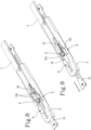
- the device for constraining the opening of doors or windows labelled 100 in its entirety, is applied on doors or windows which open towards the inside of the room or towards the outside of the room in which they are mounted.
- the door or window comprises a fixed frame 1, a movable frame or leaf 2 normally connected to the fixed frame with two or more hinges on an upright (not illustrated) to allow the rotation for opening and closing of the leaf 2.
- the door or window also comprises a control handle 3 associated with the leaf 2.
- the handle 3 is connected to devices 4 for locking/unlocking the leaf 2 slidably positioned along the perimeter profile of the leaf 2 to allow, by rotating the handle 3, at least one closed configuration of the leaf 2 and a free open configuration of the leaf 3.
- the locking / unlocking devices 4 comprise drive rods (illustrated by the dashed line) slidably positioned in channels present on the perimeter profile of the movable leaf and on which pins and/or bosses are associated.
- the movement of the rods allows the pins and/or bosses to move into contact with or away from striker elements located on the fixed frame to obtain the closed or open configuration of the movable leaf.
- the constraining device 100 comprises a guide body 5 associated with the perimeter profile of the movable leaf 2 and equipped with a slot 6 (at closed ends).
- the constraining device 100 also comprises an operating arm 7 articulated, at a first end, to the fixed frame 1, and a second end slidably connectable, by means of a pin 8, inside the slot 6 of the guide body 5 so as to allow a sliding stroke of the pin 8 along the guide slot 6 to define an open configuration with a limited angle of the leaf 2 (see Figure 2 ).
- the constraining device 100 comprises the guide body 5 provided with two lateral openings 9 facing each other made on the walls defining the slot 6 to allow a free passage, at least through one of the openings 9, of the pin 8 of the arm 7 housed in the slot 6 when the leaf 2 is in the free open configuration.
- the constraining device 100 comprises a locking lever or latch 10 articulated to a base 11 of the guide body 5 and movable between a first lowered non-operating position ( Figures 4, 5 and 7 and 13 ) and a second raised operating position ( Figures 3 , 6 , 11 and 14 ) for locking the pin 8 of the arm 7 when it is positioned at an end of the slot 6 of the guide body 5 in the open configuration with a limited angle of the leaf 2.
- the constraining device 100 also comprises an operating rod 12 slidably inserted along the guide body 6 and having its ends, outside the guide body 6, configured to connect, in use, to the devices 4 for locking / unlocking the movable leaf 2.
- the rod 12 has a pair of protruding walls 12a configured to temporarily close, in use, the openings 9 of the slot 6 at least at the passage from the closed configuration to the open configuration with a limited angle of the leaf 2.
- the leaf can be opened in the two configurations quickly and precisely by means of the handle and without intervening, if necessary, on the components of the device, which always remain positioned on the leaf also for the free opening (thanks to the presence of the openings in the slot - as described in more detail below) and, thanks to the latch controlled by the rod, the leaf is stably locked in (and released from) the open position with a constrained angle always under direct control of the handle.
- the outer ends of the rod 12 are connected, by pins, to the movement rods connected to the handle 3 so that they can slide in both directions and obtain the different configurations required.
- the operating rod 12 has a relative portion, inside the guide body 6, provided with a slot-shaped opening 13 (see also Figures 9 to 14 ) configured to intercept, during its sliding and under the action of the handle 3, a cam profile made on the latch 10 in such a way as to allow the guided passage of the latch 10 from the lowered non-operating position to the raised operating position at least at the open position with a limited angle of the leaf 2.
- the constraining device 10 comprises an elastic element 15 interposed between the base 11 of the guide body 6 and the latch 10 and able to keep the latch 10 pushed in the direction of the raised operating position.
- the elastic element 15 may be a spring interposed between the latch 10, having a suitable seat 10a, whilst the base 11 has a pin on which the spring is fitted.
- the operating rod 12 has a central zone 16 raised relative to its ends in such a way as to be inserted, without friction and with the possibility of sliding, between a sliding plane of the pin 8 of the arm 7 in the slot 6 of the guide body 5 and a seat 17 for receiving the latch 10 made in the guide body 6.
- the operating rod 12 has the above-mentioned slot-shaped opening 13 divided into two consecutive stretches 13a, 13b of which a first stretch 13a has a width L13a which is less than the width L10 of the latch 10 in such a way as to be in contact with the guide cam profiles of the latch 10 and a second stretch 13b with a width L13b which is greater than the width of the latch 10 to allow a part of the latch 10 to reach the raised operating position beyond the operating rod 12.
- the operating rod 12 has the two walls 12a for closing the openings 9 of the slot 6 protruding transversely from the raised central portion 16 in such a way as to be positioned parallel to the openings 9 of the slot for their closing, when required.
- the latch 10 has a head end 18 having a wedge-shaped profile configured for contact, in use, with the pin 8 at the open position with a limited angle of the leaf 2.
- the profile of the head 18 therefore has two surfaces which have a central vertex which acts as a point of contact with the pin 8 during locking of the pin.
- the surfaces of the head are designed to allow both the lifting without immediate connection between the head and the pin, and the lowering without locking between the head and the pin.
- the latch 10 has two lateral wings 14 having a corresponding surface for contact with the operating rod 12 with an inclined extension towards the base 11 of the guide body 6 in such a way as to define the guide cam profiles for the latch 10 at the passage from the non-operating position to the operating position and vice versa.
- the latch 10 always has a guided movement controlled by the sliding of the rod 12.
- the guide body 6 has a seat 18 for housing the latch 10 equipped with a pin 19 for articulation of the latch 10 to allow its rotation from the non-operating position to the operating position and vice versa.
- the operating rod 12 is connected, by means of the locking / unlocking devices 4, to the control handle 3 in such a way as to slide in coordination with the rotations of the handle 3 to obtain at least the open position with a limited angle according to positions between:
- the open zone of the slot therefore ensures that the leaf opens (and closes) without interaction with the pin which remains (together with the rod) positioned parallel inside the profile of the cross-member of the fixed frame.
- the preset aims are achieved thanks to a device structured in this way.
- the combination between the rod with slotted opening, vertical walls and latch makes it possible to obtain an operating precision and safety between the various positions required.
- the opening in the slot of the guide body allows traditional opening of the leaf to be obtained without intervening on the components already mounted.
- the rod with the structure passing bilaterally in the body and connected to the locking / unlocking devices allows all the operating connections present along the profile to be maintained (irrespective of the position in which the device is positioned) without necessarily having to modify the locking / unlocking structures of the door or window.
Landscapes
- Engineering & Computer Science (AREA)
- Mechanical Engineering (AREA)
- Lock And Its Accessories (AREA)
- Structures Of Non-Positive Displacement Pumps (AREA)
Claims (11)
- Dispositif pour contraindre l'ouverture de portes ou de fenêtres, comprenant un châssis fixe (1), un cadre ou vantail mobile (2), une poignée de commande (3) associée au vantail (2) ; la poignée (3) étant reliée à des dispositifs (4) de verrouillage/déverrouillage du vantail (2) positionnés de manière coulissante le long du profil périphérique du vantail (2) pour permettre, par rotation de la poignée (3), au moins une configuration de fermeture du vantail (2) et une configuration d'ouverture libre du vantail (3), le dispositif de contrainte comprenant :- un corps de guidage (5) associé au profil périphérique du vantail mobile (2) et comportant une fente (6) ;- un bras d'actionnement (7) monté articulé, à une première extrémité, au châssis fixe (1), et à une deuxième extrémité reliée de manière coulissante, par une broche (8), à l'intérieur de la fente (6) du corps de guidage (5) de manière à permettre une course de coulissement de la broche (8) le long de la fente de guidage (6) pour définir une configuration d'ouverture avec un angle limité du vantail (2) ; caractérisé en ce qu'il comprend :- le corps de guidage (5) pourvu de deux ouvertures latérales (9), se faisant face, réalisées sur les parois définissant la fente (6) pour permettre un libre passage, au moins à travers l'une des ouvertures (9), de la broche (8) du bras (7) logé dans la fente (6) lorsque le vantail (2) se trouve dans la configuration d'ouverture libre ;- un levier de verrouillage ou loquet (10) monté articulé à une base (11) du corps de guidage (5) et mobile entre une première position de non fonctionnement abaissée et une deuxième position de fonctionnement relevée pour verrouiller la broche (8) du bras (7) lorsqu'il est positionné à une extrémité de la fente (6) du corps de guidage (5) dans la configuration d'ouverture avec un angle limité du vantail (2) ;- une tige d'actionnement (12) insérée de manière coulissante le long du corps de guidage (6) et ayant ses extrémités, à l'extérieur du corps de guidage (6), configurée pour se raccorder, lors de l'utilisation, aux dispositifs (4) de verrouillage/déverrouillage du vantail mobile (2) ; ladite tige (12) comportant une paire de parois saillantes (12a) configurées pour fermer temporairement, lors de l'utilisation, les ouvertures (9) de la fente (6) au moins en correspondance du passage de la configuration de fermeture à la configuration d'ouverture avec un angle limité du vantail (2).
- Dispositif selon la revendication 1, dans lequel la tige d'actionnement (12) comporte une partie relative, à l'intérieur du corps de guidage (6), pourvue d'une ouverture en forme de fente (13) configurée pour intercepter, lors de son coulissement et sous l'action de la poignée (3), un profil de came réalisé sur le loquet (10) de manière à permettre le passage guidé du loquet (10) de la position abaissée de non fonctionnement à la position relevée de fonctionnement au moins en correspondance de la position d'ouverture avec un angle limité du vantail (2).
- Dispositif selon la revendication 1 ou 2, comprenant un élément élastique (15) interposé entre la base (11) du corps de guidage (6) et le loquet (10) et capable de maintenir le loquet (10) poussé en direction de la position relevée de fonctionnement.
- Dispositif selon l'une quelconque des revendications précédentes, dans lequel la tige d'actionnement (12) comporte une zone centrale (16) relevée par rapport à ses extrémités de manière à s'introduire, sans frottement et avec la possibilité de coulissement, entre un plan de coulissement de la broche (8) du bras (7) dans la fente (6) du corps de guidage (5) et un siège (17) de réception du loquet (10) dans le corps de guidage (6) .
- Dispositif selon l'une quelconque des revendications précédentes, dans lequel le loquet (10) comporte une extrémité de tête (18) ayant un profil cunéiforme configuré pour être en contact, lors de l'utilisation, avec la broche (8) en correspondance de la position d'ouverture avec un angle limité du vantail (2).
- Dispositif selon l'une quelconque des revendications 2 à 5, dans lequel le loquet (10) comporte deux ailes latérales (14) comportant une surface correspondante de contact avec la tige d'actionnement (12) avec une extension inclinée vers la base (11) du corps de guidage (6) de manière à définir les profils de came de guidage du loquet (10) lors du passage de la position de non fonctionnement à la position de fonctionnement et vice versa.
- Dispositif selon l'une quelconque des revendications 2 à 6, dans lequel la tige d'actionnement (12) comporte l'ouverture en forme de fente (13) divisée en deux tronçons consécutifs (13a, 13b) dont un premier tronçon (13a) ayant une largeur (L13a) étant inférieure à la largeur (L10) du loquet (10) de manière à être en contact avec les profils de came de guidage du loquet (10) et un deuxième tronçon (13b) ayant une largeur (L13b) supérieure à la largeur du loquet (10) pour permettre à une partie du loquet (10) d'atteindre la position relevée de fonctionnement au-delà de la tige d'actionnement (12) .
- Dispositif selon l'une quelconque des revendications précédentes, dans lequel le corps de guidage (6) comporte un siège (18) pour loger le loquet (10) équipé d'une broche (19) pour l'articulation du loquet (10) afin de permettre sa rotation de la position de non fonctionnement à la position de fonctionnement et vice versa.
- Dispositif selon l'une quelconque des revendications 4 à 8, dans lequel la tige d'actionnement (12) comporte les deux parois (12a) pour fermer les ouvertures (9) de la fente (6) faisant saillie transversalement à partir de la partie centrale relevée (16) de manière à se positionner parallèlement aux ouvertures (9) de la fente pour leur fermeture, lorsque cela est nécessaire.
- Dispositif selon l'une quelconque des revendications précédentes, dans lequel la tige d'actionnement (12) est reliée, au moyen des dispositifs de verrouillage / déverrouillage (4), à la poignée de commande (3) de manière à coulisser en coordination avec les rotations de la poignée (3) pour obtenir au moins la position d'ouverture avec un angle limité selon des positions comprises entre :- une position de fermeture du vantail (2) correspondant à une première position de la poignée (3), dans laquelle la tige (12) se trouve dans une première position avec les parois (12a) éloignées des ouvertures (9) de la fente (6) du corps de guidage (5) et le loquet (10) se trouve dans la position relevée de fonctionnement ;- une rotation de la poignée (3) dans une position d'ouverture avec un angle limité du vantail (2), dans laquelle la tige (12) se trouve dans une deuxième position dans laquelle les parois (12a) se trouvent dans une position de fermeture des ouvertures (9) de la fente (6) du corps de guidage (5) et le loquet (10) se trouve dans la position abaissée de non fonctionnement de manière à permettre à la broche (8) du bras (7) de coulisser le long de la fente (6) pour obtenir l'ouverture du vantail (2) avec un angle limité ;- une rotation de retour de la poignée (3) vers la position de fermeture du vantail (2), dans laquelle la tige (12) revient à la première position avec les parois (12a) éloignées des ouvertures (9) de la fente (6) du corps de guidage (5) et le loquet (10) se trouve en position relevée de fonctionnement de manière à bloquer la broche (8) du bras (7) dans la position atteinte ;- une rotation supplémentaire de la poignée (3) vers la position d'ouverture avec un angle limité du vantail (2), dans laquelle la tige (12) revient à la deuxième position dans laquelle les parois (12a) ferment les ouvertures (9) de la fente (6) du corps de guidage (5) et le loquet (10) se trouve dans la position abaissée de non fonctionnement de manière à permettre à la broche (8) du bras (7) de coulisser le long de la fente (6), dans la direction opposée, pour permettre au vantail (2) de revenir à la position de fermeture.
- Dispositif selon la revendication 10, dans lequel la tige d'actionnement (12) est reliée, au moyen des dispositifs de verrouillage/déverrouillage (4), à la poignée de commande (3) de manière à coulisser en coordination avec les rotations de la poignée (3) pour obtenir la position d'ouverture libre du vantail (2) entre :- la position de fermeture du vantail (2) correspondant à la première position de la poignée (3), dans laquelle la tige (12) se trouve dans la première position avec les parois (12a) éloignées des ouvertures (9) de la fente (6) du corps de guidage (5) et le loquet (10) se trouve dans la position relevée de fonctionnement ;- une deuxième rotation de la poignée (3) angulairement différente de sa première rotation, dans laquelle la tige (12) se trouve dans une troisième position avec les parois (12a) éloignées des ouvertures (9) de la fente (6) du corps de guidage (5) et le loquet (10) se trouve dans la position abaissée de non fonctionnement, de manière à faire tourner le vantail (2) tout en maintenant le bras (7) et la broche (8) immobiles à l'intérieur du châssis fixe (1).
Applications Claiming Priority (1)
| Application Number | Priority Date | Filing Date | Title |
|---|---|---|---|
| IT202000028376 | 2020-11-25 |
Publications (2)
| Publication Number | Publication Date |
|---|---|
| EP4006277A1 EP4006277A1 (fr) | 2022-06-01 |
| EP4006277B1 true EP4006277B1 (fr) | 2023-05-10 |
Family
ID=74347642
Family Applications (1)
| Application Number | Title | Priority Date | Filing Date |
|---|---|---|---|
| EP21208397.6A Active EP4006277B1 (fr) | 2020-11-25 | 2021-11-16 | Dispositif pour contraindre l'ouverture de portes ou de fenêtres |
Country Status (3)
| Country | Link |
|---|---|
| US (1) | US11866966B2 (fr) |
| EP (1) | EP4006277B1 (fr) |
| CN (1) | CN114541896B (fr) |
Cited By (1)
| Publication number | Priority date | Publication date | Assignee | Title |
|---|---|---|---|---|
| EP4628689A1 (fr) * | 2024-03-06 | 2025-10-08 | Aug. Winkhaus SE | Dispositif de limitation d'ouverture pour une crémone |
Families Citing this family (3)
| Publication number | Priority date | Publication date | Assignee | Title |
|---|---|---|---|---|
| EP4174264B1 (fr) * | 2021-10-26 | 2025-08-06 | Gretsch-Unitas GmbH Baubeschläge | Agencement de battant |
| EP4174265B1 (fr) * | 2021-10-26 | 2026-04-08 | Gretsch-Unitas GmbH Baubeschläge | Agencement de battant |
| EP4174266A1 (fr) * | 2021-10-26 | 2023-05-03 | Gretsch-Unitas GmbH Baubeschläge | Agencement de battant |
Family Cites Families (53)
| Publication number | Priority date | Publication date | Assignee | Title |
|---|---|---|---|---|
| DE338646C (de) * | 1920-10-09 | 1921-06-01 | Thomas Peter Eustege | Fensterfeststeller u. dgl. |
| US2095671A (en) * | 1936-01-09 | 1937-10-12 | Union Switch & Signal Co | Door latch |
| US2277316A (en) * | 1941-01-02 | 1942-03-24 | Oscar C Rixson Company | Door holder |
| US2497830A (en) * | 1945-10-04 | 1950-02-14 | American Hardware Corp | Door holder |
| US2593312A (en) * | 1948-09-16 | 1952-04-15 | Western Electric Co | Lid support |
| US2961234A (en) * | 1957-11-12 | 1960-11-22 | Parlyn Inc | Window operator with improved track |
| US2958089A (en) * | 1958-06-23 | 1960-11-01 | Kawneer Co | Door back-check and hold open mechanism |
| US3601842A (en) * | 1970-06-22 | 1971-08-31 | Rixson Inc | Door holder |
| US3630560A (en) * | 1970-11-12 | 1971-12-28 | Glynn Johnson Corp | Surface-mounted nonhanded door holder |
| US4042266A (en) * | 1976-07-16 | 1977-08-16 | A. W. Anderberg Manufacturing Co. | Extensible safety latch means for pivotable windows |
| US4087883A (en) * | 1976-11-15 | 1978-05-09 | Keystone Consolidated Industries, Inc. | Door support |
| FR2520038A1 (fr) * | 1982-01-20 | 1983-07-22 | Ds Croisee | Dispositif entrebailleur pour battant de porte ou de fenetre |
| US4751766A (en) * | 1985-06-07 | 1988-06-21 | Coachmen Industries | Door hold open device |
| US4984331A (en) * | 1985-12-18 | 1991-01-15 | Richard Hucknall | Door holder including a removable cam |
| US4750236A (en) * | 1987-01-02 | 1988-06-14 | Yale Security Inc. | Track-type door hold-open device |
| US4858272A (en) * | 1987-01-30 | 1989-08-22 | Ryobi Ltd. | Door closing device |
| DE3806662C2 (de) * | 1987-03-05 | 1999-06-10 | Geze Grundstueck Beteiligung | Feststellvorrichtung für eine mit einem Türschließer versehene Tür |
| US4955159A (en) * | 1989-07-12 | 1990-09-11 | Schlegel Corporation | Retaining catch for tip-out sash |
| US4932695A (en) * | 1989-12-11 | 1990-06-12 | Truth Incorporated | Support arm with passive lock system |
| US4958867A (en) * | 1990-01-31 | 1990-09-25 | Champagne Phillip A | Locking device for washers and dryers |
| US5002320A (en) * | 1990-05-24 | 1991-03-26 | Anthony's Manufacturing Co., Inc. | Sliding hold-open |
| EP0553523B1 (fr) * | 1992-02-11 | 1995-09-06 | Kabushiki Kaisha Yagi | Bras de support télescopique |
| US5419165A (en) * | 1993-12-08 | 1995-05-30 | Perkins; Jon T. | Electrical panel locking apparatus |
| GB2306564B (en) * | 1995-10-27 | 1999-08-18 | Euromond Ltd | Stays |
| FR2740504B1 (fr) * | 1995-10-27 | 1998-02-27 | Ferco Int Usine Ferrures | Dispositif de maintien d'un ouvrant dans une position entrebaillee |
| GB2309484A (en) * | 1996-01-24 | 1997-07-30 | Euromond Ltd | Door or window stay |
| FI100548B (fi) * | 1996-09-02 | 1997-12-31 | Abloy Oy | Oven aukipitolaite |
| GB9624078D0 (en) * | 1996-11-20 | 1997-01-08 | Raytec Pressworks Plastics Ltd | Sliding catch |
| US5865485A (en) * | 1997-10-30 | 1999-02-02 | Lawhorne, Jr.; Jesse H. | Vehicle door locking system |
| EP0962614A3 (fr) * | 1998-05-05 | 2002-04-03 | Milenko Vujko | Dispositif d'arrêt à positions discrètes pour fenêtre |
| US6253417B1 (en) * | 1999-09-30 | 2001-07-03 | Architectural Builders Hardware Mfg., Inc. | Door holder and stop with retaining means for holding a door shut while in a closed position |
| US6347817B1 (en) * | 2000-03-07 | 2002-02-19 | Yeh-Chien Chou | Locking device for use in a cargo support to lock a retractable tube |
| CZ293782B6 (cs) * | 2003-03-18 | 2004-07-14 | Tokoz A. S. | Teleskopická okenní rozpěra |
| DE10314079A1 (de) * | 2003-03-28 | 2004-10-28 | Wilh. Schlechtendahl & Söhne GmbH & Co KG | Rasteinrichtung für ein in einer Führung verschiebliches Gleitstück |
| JP5042825B2 (ja) * | 2005-06-20 | 2012-10-03 | スガツネ工業株式会社 | 伸縮ステー |
| DE102005000195A1 (de) * | 2005-12-21 | 2007-06-28 | Siegenia-Aubi Kg | Gleitstück für einen Beschlag |
| EP2157267A1 (fr) * | 2008-08-20 | 2010-02-24 | Jeld Wen Türen GmbH | Porte dotée d'un mécanisme intégré |
| DE102008048992B4 (de) * | 2008-09-25 | 2013-05-16 | Geze Gmbh | Feststellvorrichtung für einen Flügel einer Tür |
| JP5350326B2 (ja) * | 2010-06-04 | 2013-11-27 | Ykk Ap株式会社 | 建具 |
| US8418404B2 (en) * | 2010-08-16 | 2013-04-16 | Andersen Corporation | Window with opening control mechanism |
| DE102010046402A1 (de) * | 2010-09-23 | 2012-03-29 | Assa Abloy Sicherheitstechnik Gmbh | Arretiereinheit zum Feststellen einer Tür in einer Haltestellung, Türschließsystem mit einer solchen Arretiereinheit und Verfahren zum Betrieb einer solchen Arretiereinheit |
| US8844202B2 (en) * | 2011-07-01 | 2014-09-30 | U.S.F. Fabrication, Inc. | Latching mechanism for access door |
| DE102011119333B3 (de) * | 2011-11-25 | 2012-07-26 | Assa Abloy Sicherheitstechnik Gmbh | Feststellvorrichtung für eine Tür, vorzugsweise mit Türschließer |
| US9032587B2 (en) * | 2013-02-08 | 2015-05-19 | Barnes Group Inc. | Universal stop tube |
| DE102013113915A1 (de) * | 2013-12-12 | 2015-06-18 | Eco Schulte Gmbh & Co. Kg | Federklemmung mit Öffnungsbegrenzer |
| JP6178248B2 (ja) * | 2014-01-15 | 2017-08-09 | Ykk Ap株式会社 | 建具 |
| RS59234B1 (sr) * | 2014-04-04 | 2019-10-31 | Fapim S P A | Uređaj za otvaranje/zatvaranje prozora sa elementom za zaustavljanje krila prozora u otvorenom položaju |
| TR201807280T4 (tr) * | 2014-12-18 | 2018-06-21 | Wilh Schlechtendahl & Soehne Gmbh & Co Kg | Açılmayı sınırlama düzeneği. |
| US10196844B2 (en) * | 2015-01-07 | 2019-02-05 | Electronic Power Design, Inc. | Variable resistance door stay apparatus |
| DE202015008146U1 (de) * | 2015-10-29 | 2016-01-08 | Wilh. Schlechtendahl & Söhne GmbH & Co. KG | Öffnungsbegrenzungseinrichtung |
| DE102017202797A1 (de) | 2017-02-21 | 2018-08-23 | Roto Frank Ag | Drehöffnungsbegrenzungsanordnung für ein Fenster oder eine Tür zur Begrenzung der Drehöffnungsbewegung eines Flügels eines Fensters oder einer Tür |
| CN210118027U (zh) * | 2019-05-15 | 2020-02-28 | 厦门市百思得铝制品工程有限公司 | 一种限开角度的安全门窗 |
| ES2900545T3 (es) | 2019-10-29 | 2022-03-17 | Wilh Schlechtendahl & Soehne Gmbh & Co Kg | Pieza de herraje de seguridad, así como disposición de herraje y disposición de marco y hoja |
-
2021
- 2021-11-16 EP EP21208397.6A patent/EP4006277B1/fr active Active
- 2021-11-23 US US17/534,451 patent/US11866966B2/en active Active
- 2021-11-24 CN CN202111406158.5A patent/CN114541896B/zh active Active
Cited By (1)
| Publication number | Priority date | Publication date | Assignee | Title |
|---|---|---|---|---|
| EP4628689A1 (fr) * | 2024-03-06 | 2025-10-08 | Aug. Winkhaus SE | Dispositif de limitation d'ouverture pour une crémone |
Also Published As
| Publication number | Publication date |
|---|---|
| EP4006277A1 (fr) | 2022-06-01 |
| CN114541896A (zh) | 2022-05-27 |
| US11866966B2 (en) | 2024-01-09 |
| CN114541896B (zh) | 2026-02-17 |
| US20220162890A1 (en) | 2022-05-26 |
Similar Documents
| Publication | Publication Date | Title |
|---|---|---|
| EP4006277B1 (fr) | Dispositif pour contraindre l'ouverture de portes ou de fenêtres | |
| US5568702A (en) | Vent and tilt roof window | |
| US5090750A (en) | Locking mechanism for sash type windows | |
| AU639631B2 (en) | A window operator and hinge structure | |
| US4452012A (en) | Pivot shoe for sash balance | |
| US4420905A (en) | Closure hardware | |
| US5568703A (en) | Roof window | |
| CA2824909C (fr) | Verrou profile pour fenetre a battant | |
| US4620393A (en) | Turnable window arrangement having a stop device for a partially open position | |
| US20050072075A1 (en) | Latching and anti-bow mechanism for a window | |
| US5289656A (en) | Geared casement window hinges | |
| EP1612354A2 (fr) | Ensemble de compas pour une fenêtre ou porte oscillo-battante | |
| US4339892A (en) | Safety window of the tilt and turn type | |
| US7490873B1 (en) | Tilt latch/sash lock assembly for windows | |
| US20230323714A1 (en) | Friction hinge for outward opening top hung windows | |
| EP3122974B1 (fr) | Mécanisme pour fenêtre pivotante | |
| EP3315700A1 (fr) | Ensemble de porte coulissante et pivotante, son mécanisme de support et mécanisme d'actionnement pour fixer le mécanisme de support | |
| KR102147697B1 (ko) | 적어도 리프팅 되며, 바람직하게는 슬라이딩 될 수 있는 윈도우 또는 도어의 윙을 위한 피팅장치. | |
| EP3428376A1 (fr) | Ferrure pour une aile inclinable et coulissante et procédé d'ouverture et de fermeture d'une aile parallèlement réglable et coulissante | |
| HU223254B1 (hu) | Zárószerkezet kétszárnyú, középoszlop nélküli nyílászáró szerkezetek alázáródó szárnyához | |
| KR20090131872A (ko) | 개선된 힌지부를 가지는 프로젝트 및 케이스먼트 운동이가능한 창호 | |
| PL208795B1 (pl) | Okucie rozwierno-uchylne | |
| JP2524824Y2 (ja) | 開き窓のあおり止め装置 | |
| PL182553B1 (pl) | Okucie obrotowo-wychylne do okien i drzwi | |
| KR102284723B1 (ko) | 폴딩 도어용 잠금장치 |
Legal Events
| Date | Code | Title | Description |
|---|---|---|---|
| PUAI | Public reference made under article 153(3) epc to a published international application that has entered the european phase |
Free format text: ORIGINAL CODE: 0009012 |
|
| STAA | Information on the status of an ep patent application or granted ep patent |
Free format text: STATUS: THE APPLICATION HAS BEEN PUBLISHED |
|
| AK | Designated contracting states |
Kind code of ref document: A1 Designated state(s): AL AT BE BG CH CY CZ DE DK EE ES FI FR GB GR HR HU IE IS IT LI LT LU LV MC MK MT NL NO PL PT RO RS SE SI SK SM TR |
|
| STAA | Information on the status of an ep patent application or granted ep patent |
Free format text: STATUS: REQUEST FOR EXAMINATION WAS MADE |
|
| 17P | Request for examination filed |
Effective date: 20220613 |
|
| RBV | Designated contracting states (corrected) |
Designated state(s): AL AT BE BG CH CY CZ DE DK EE ES FI FR GB GR HR HU IE IS IT LI LT LU LV MC MK MT NL NO PL PT RO RS SE SI SK SM TR |
|
| GRAP | Despatch of communication of intention to grant a patent |
Free format text: ORIGINAL CODE: EPIDOSNIGR1 |
|
| STAA | Information on the status of an ep patent application or granted ep patent |
Free format text: STATUS: GRANT OF PATENT IS INTENDED |
|
| INTG | Intention to grant announced |
Effective date: 20221212 |
|
| RIN1 | Information on inventor provided before grant (corrected) |
Inventor name: SANTO, PETER REGINALD |
|
| GRAS | Grant fee paid |
Free format text: ORIGINAL CODE: EPIDOSNIGR3 |
|
| GRAA | (expected) grant |
Free format text: ORIGINAL CODE: 0009210 |
|
| STAA | Information on the status of an ep patent application or granted ep patent |
Free format text: STATUS: THE PATENT HAS BEEN GRANTED |
|
| AK | Designated contracting states |
Kind code of ref document: B1 Designated state(s): AL AT BE BG CH CY CZ DE DK EE ES FI FR GB GR HR HU IE IS IT LI LT LU LV MC MK MT NL NO PL PT RO RS SE SI SK SM TR |
|
| REG | Reference to a national code |
Ref country code: GB Ref legal event code: FG4D |
|
| REG | Reference to a national code |
Ref country code: AT Ref legal event code: REF Ref document number: 1566829 Country of ref document: AT Kind code of ref document: T Effective date: 20230515 Ref country code: CH Ref legal event code: EP |
|
| REG | Reference to a national code |
Ref country code: DE Ref legal event code: R096 Ref document number: 602021002327 Country of ref document: DE |
|
| REG | Reference to a national code |
Ref country code: IE Ref legal event code: FG4D |
|
| P01 | Opt-out of the competence of the unified patent court (upc) registered |
Effective date: 20230506 |
|
| REG | Reference to a national code |
Ref country code: LT Ref legal event code: MG9D |
|
| REG | Reference to a national code |
Ref country code: NL Ref legal event code: MP Effective date: 20230510 |
|
| REG | Reference to a national code |
Ref country code: AT Ref legal event code: MK05 Ref document number: 1566829 Country of ref document: AT Kind code of ref document: T Effective date: 20230510 |
|
| PG25 | Lapsed in a contracting state [announced via postgrant information from national office to epo] |
Ref country code: SE Free format text: LAPSE BECAUSE OF FAILURE TO SUBMIT A TRANSLATION OF THE DESCRIPTION OR TO PAY THE FEE WITHIN THE PRESCRIBED TIME-LIMIT Effective date: 20230510 Ref country code: PT Free format text: LAPSE BECAUSE OF FAILURE TO SUBMIT A TRANSLATION OF THE DESCRIPTION OR TO PAY THE FEE WITHIN THE PRESCRIBED TIME-LIMIT Effective date: 20230911 Ref country code: NO Free format text: LAPSE BECAUSE OF FAILURE TO SUBMIT A TRANSLATION OF THE DESCRIPTION OR TO PAY THE FEE WITHIN THE PRESCRIBED TIME-LIMIT Effective date: 20230810 Ref country code: NL Free format text: LAPSE BECAUSE OF FAILURE TO SUBMIT A TRANSLATION OF THE DESCRIPTION OR TO PAY THE FEE WITHIN THE PRESCRIBED TIME-LIMIT Effective date: 20230510 Ref country code: ES Free format text: LAPSE BECAUSE OF FAILURE TO SUBMIT A TRANSLATION OF THE DESCRIPTION OR TO PAY THE FEE WITHIN THE PRESCRIBED TIME-LIMIT Effective date: 20230510 Ref country code: AT Free format text: LAPSE BECAUSE OF FAILURE TO SUBMIT A TRANSLATION OF THE DESCRIPTION OR TO PAY THE FEE WITHIN THE PRESCRIBED TIME-LIMIT Effective date: 20230510 |
|
| PG25 | Lapsed in a contracting state [announced via postgrant information from national office to epo] |
Ref country code: RS Free format text: LAPSE BECAUSE OF FAILURE TO SUBMIT A TRANSLATION OF THE DESCRIPTION OR TO PAY THE FEE WITHIN THE PRESCRIBED TIME-LIMIT Effective date: 20230510 Ref country code: PL Free format text: LAPSE BECAUSE OF FAILURE TO SUBMIT A TRANSLATION OF THE DESCRIPTION OR TO PAY THE FEE WITHIN THE PRESCRIBED TIME-LIMIT Effective date: 20230510 Ref country code: LV Free format text: LAPSE BECAUSE OF FAILURE TO SUBMIT A TRANSLATION OF THE DESCRIPTION OR TO PAY THE FEE WITHIN THE PRESCRIBED TIME-LIMIT Effective date: 20230510 Ref country code: LT Free format text: LAPSE BECAUSE OF FAILURE TO SUBMIT A TRANSLATION OF THE DESCRIPTION OR TO PAY THE FEE WITHIN THE PRESCRIBED TIME-LIMIT Effective date: 20230510 Ref country code: IS Free format text: LAPSE BECAUSE OF FAILURE TO SUBMIT A TRANSLATION OF THE DESCRIPTION OR TO PAY THE FEE WITHIN THE PRESCRIBED TIME-LIMIT Effective date: 20230910 Ref country code: HR Free format text: LAPSE BECAUSE OF FAILURE TO SUBMIT A TRANSLATION OF THE DESCRIPTION OR TO PAY THE FEE WITHIN THE PRESCRIBED TIME-LIMIT Effective date: 20230510 Ref country code: GR Free format text: LAPSE BECAUSE OF FAILURE TO SUBMIT A TRANSLATION OF THE DESCRIPTION OR TO PAY THE FEE WITHIN THE PRESCRIBED TIME-LIMIT Effective date: 20230811 |
|
| PG25 | Lapsed in a contracting state [announced via postgrant information from national office to epo] |
Ref country code: FI Free format text: LAPSE BECAUSE OF FAILURE TO SUBMIT A TRANSLATION OF THE DESCRIPTION OR TO PAY THE FEE WITHIN THE PRESCRIBED TIME-LIMIT Effective date: 20230510 |
|
| PG25 | Lapsed in a contracting state [announced via postgrant information from national office to epo] |
Ref country code: SK Free format text: LAPSE BECAUSE OF FAILURE TO SUBMIT A TRANSLATION OF THE DESCRIPTION OR TO PAY THE FEE WITHIN THE PRESCRIBED TIME-LIMIT Effective date: 20230510 |
|
| PG25 | Lapsed in a contracting state [announced via postgrant information from national office to epo] |
Ref country code: SM Free format text: LAPSE BECAUSE OF FAILURE TO SUBMIT A TRANSLATION OF THE DESCRIPTION OR TO PAY THE FEE WITHIN THE PRESCRIBED TIME-LIMIT Effective date: 20230510 Ref country code: SK Free format text: LAPSE BECAUSE OF FAILURE TO SUBMIT A TRANSLATION OF THE DESCRIPTION OR TO PAY THE FEE WITHIN THE PRESCRIBED TIME-LIMIT Effective date: 20230510 Ref country code: RO Free format text: LAPSE BECAUSE OF FAILURE TO SUBMIT A TRANSLATION OF THE DESCRIPTION OR TO PAY THE FEE WITHIN THE PRESCRIBED TIME-LIMIT Effective date: 20230510 Ref country code: EE Free format text: LAPSE BECAUSE OF FAILURE TO SUBMIT A TRANSLATION OF THE DESCRIPTION OR TO PAY THE FEE WITHIN THE PRESCRIBED TIME-LIMIT Effective date: 20230510 Ref country code: DK Free format text: LAPSE BECAUSE OF FAILURE TO SUBMIT A TRANSLATION OF THE DESCRIPTION OR TO PAY THE FEE WITHIN THE PRESCRIBED TIME-LIMIT Effective date: 20230510 Ref country code: CZ Free format text: LAPSE BECAUSE OF FAILURE TO SUBMIT A TRANSLATION OF THE DESCRIPTION OR TO PAY THE FEE WITHIN THE PRESCRIBED TIME-LIMIT Effective date: 20230510 |
|
| REG | Reference to a national code |
Ref country code: DE Ref legal event code: R097 Ref document number: 602021002327 Country of ref document: DE |
|
| PLBE | No opposition filed within time limit |
Free format text: ORIGINAL CODE: 0009261 |
|
| STAA | Information on the status of an ep patent application or granted ep patent |
Free format text: STATUS: NO OPPOSITION FILED WITHIN TIME LIMIT |
|
| 26N | No opposition filed |
Effective date: 20240213 |
|
| PG25 | Lapsed in a contracting state [announced via postgrant information from national office to epo] |
Ref country code: SI Free format text: LAPSE BECAUSE OF FAILURE TO SUBMIT A TRANSLATION OF THE DESCRIPTION OR TO PAY THE FEE WITHIN THE PRESCRIBED TIME-LIMIT Effective date: 20230510 |
|
| PG25 | Lapsed in a contracting state [announced via postgrant information from national office to epo] |
Ref country code: SI Free format text: LAPSE BECAUSE OF FAILURE TO SUBMIT A TRANSLATION OF THE DESCRIPTION OR TO PAY THE FEE WITHIN THE PRESCRIBED TIME-LIMIT Effective date: 20230510 |
|
| PG25 | Lapsed in a contracting state [announced via postgrant information from national office to epo] |
Ref country code: MC Free format text: LAPSE BECAUSE OF FAILURE TO SUBMIT A TRANSLATION OF THE DESCRIPTION OR TO PAY THE FEE WITHIN THE PRESCRIBED TIME-LIMIT Effective date: 20230510 |
|
| PG25 | Lapsed in a contracting state [announced via postgrant information from national office to epo] |
Ref country code: LU Free format text: LAPSE BECAUSE OF NON-PAYMENT OF DUE FEES Effective date: 20231116 |
|
| PG25 | Lapsed in a contracting state [announced via postgrant information from national office to epo] |
Ref country code: MC Free format text: LAPSE BECAUSE OF FAILURE TO SUBMIT A TRANSLATION OF THE DESCRIPTION OR TO PAY THE FEE WITHIN THE PRESCRIBED TIME-LIMIT Effective date: 20230510 Ref country code: LU Free format text: LAPSE BECAUSE OF NON-PAYMENT OF DUE FEES Effective date: 20231116 |
|
| REG | Reference to a national code |
Ref country code: BE Ref legal event code: MM Effective date: 20231130 |
|
| REG | Reference to a national code |
Ref country code: IE Ref legal event code: MM4A |
|
| PG25 | Lapsed in a contracting state [announced via postgrant information from national office to epo] |
Ref country code: IE Free format text: LAPSE BECAUSE OF NON-PAYMENT OF DUE FEES Effective date: 20231116 |
|
| PG25 | Lapsed in a contracting state [announced via postgrant information from national office to epo] |
Ref country code: BE Free format text: LAPSE BECAUSE OF NON-PAYMENT OF DUE FEES Effective date: 20231130 |
|
| PG25 | Lapsed in a contracting state [announced via postgrant information from national office to epo] |
Ref country code: FR Free format text: LAPSE BECAUSE OF NON-PAYMENT OF DUE FEES Effective date: 20231130 |
|
| PG25 | Lapsed in a contracting state [announced via postgrant information from national office to epo] |
Ref country code: IE Free format text: LAPSE BECAUSE OF NON-PAYMENT OF DUE FEES Effective date: 20231116 Ref country code: FR Free format text: LAPSE BECAUSE OF NON-PAYMENT OF DUE FEES Effective date: 20231130 Ref country code: BE Free format text: LAPSE BECAUSE OF NON-PAYMENT OF DUE FEES Effective date: 20231130 |
|
| PG25 | Lapsed in a contracting state [announced via postgrant information from national office to epo] |
Ref country code: BG Free format text: LAPSE BECAUSE OF FAILURE TO SUBMIT A TRANSLATION OF THE DESCRIPTION OR TO PAY THE FEE WITHIN THE PRESCRIBED TIME-LIMIT Effective date: 20230510 |
|
| PG25 | Lapsed in a contracting state [announced via postgrant information from national office to epo] |
Ref country code: BG Free format text: LAPSE BECAUSE OF FAILURE TO SUBMIT A TRANSLATION OF THE DESCRIPTION OR TO PAY THE FEE WITHIN THE PRESCRIBED TIME-LIMIT Effective date: 20230510 |
|
| REG | Reference to a national code |
Ref country code: CH Ref legal event code: PL |
|
| REG | Reference to a national code |
Ref country code: CH Ref legal event code: PL |
|
| PG25 | Lapsed in a contracting state [announced via postgrant information from national office to epo] |
Ref country code: CH Free format text: LAPSE BECAUSE OF NON-PAYMENT OF DUE FEES Effective date: 20241130 |
|
| PG25 | Lapsed in a contracting state [announced via postgrant information from national office to epo] |
Ref country code: CY Free format text: LAPSE BECAUSE OF FAILURE TO SUBMIT A TRANSLATION OF THE DESCRIPTION OR TO PAY THE FEE WITHIN THE PRESCRIBED TIME-LIMIT; INVALID AB INITIO Effective date: 20211116 |
|
| PGFP | Annual fee paid to national office [announced via postgrant information from national office to epo] |
Ref country code: DE Payment date: 20251126 Year of fee payment: 5 |
|
| PGFP | Annual fee paid to national office [announced via postgrant information from national office to epo] |
Ref country code: GB Payment date: 20251125 Year of fee payment: 5 |
|
| PGFP | Annual fee paid to national office [announced via postgrant information from national office to epo] |
Ref country code: IT Payment date: 20251128 Year of fee payment: 5 |
|
| PGFP | Annual fee paid to national office [announced via postgrant information from national office to epo] |
Ref country code: TR Payment date: 20251030 Year of fee payment: 5 |
|
| PG25 | Lapsed in a contracting state [announced via postgrant information from national office to epo] |
Ref country code: HU Free format text: LAPSE BECAUSE OF FAILURE TO SUBMIT A TRANSLATION OF THE DESCRIPTION OR TO PAY THE FEE WITHIN THE PRESCRIBED TIME-LIMIT; INVALID AB INITIO Effective date: 20211116 |