EP4006367B1 - Gaslagersystem - Google Patents
Gaslagersystem Download PDFInfo
- Publication number
- EP4006367B1 EP4006367B1 EP20210368.5A EP20210368A EP4006367B1 EP 4006367 B1 EP4006367 B1 EP 4006367B1 EP 20210368 A EP20210368 A EP 20210368A EP 4006367 B1 EP4006367 B1 EP 4006367B1
- Authority
- EP
- European Patent Office
- Prior art keywords
- bearing
- ultrasonic vibration
- pump
- bearing assembly
- gas
- Prior art date
- Legal status (The legal status is an assumption and is not a legal conclusion. Google has not performed a legal analysis and makes no representation as to the accuracy of the status listed.)
- Active
Links
Images







Classifications
-
- B—PERFORMING OPERATIONS; TRANSPORTING
- B64—AIRCRAFT; AVIATION; COSMONAUTICS
- B64G—COSMONAUTICS; VEHICLES OR EQUIPMENT THEREFOR
- B64G1/00—Cosmonautic vehicles
- B64G1/22—Parts of, or equipment specially adapted for fitting in or to, cosmonautic vehicles
-
- F—MECHANICAL ENGINEERING; LIGHTING; HEATING; WEAPONS; BLASTING
- F16—ENGINEERING ELEMENTS AND UNITS; GENERAL MEASURES FOR PRODUCING AND MAINTAINING EFFECTIVE FUNCTIONING OF MACHINES OR INSTALLATIONS; THERMAL INSULATION IN GENERAL
- F16C—SHAFTS; FLEXIBLE SHAFTS; ELEMENTS OR CRANKSHAFT MECHANISMS; ROTARY BODIES OTHER THAN GEARING ELEMENTS; BEARINGS
- F16C17/00—Sliding-contact bearings for exclusively rotary movement
- F16C17/02—Sliding-contact bearings for exclusively rotary movement for radial load only
-
- F—MECHANICAL ENGINEERING; LIGHTING; HEATING; WEAPONS; BLASTING
- F16—ENGINEERING ELEMENTS AND UNITS; GENERAL MEASURES FOR PRODUCING AND MAINTAINING EFFECTIVE FUNCTIONING OF MACHINES OR INSTALLATIONS; THERMAL INSULATION IN GENERAL
- F16C—SHAFTS; FLEXIBLE SHAFTS; ELEMENTS OR CRANKSHAFT MECHANISMS; ROTARY BODIES OTHER THAN GEARING ELEMENTS; BEARINGS
- F16C17/00—Sliding-contact bearings for exclusively rotary movement
- F16C17/04—Sliding-contact bearings for exclusively rotary movement for axial load only
-
- F—MECHANICAL ENGINEERING; LIGHTING; HEATING; WEAPONS; BLASTING
- F16—ENGINEERING ELEMENTS AND UNITS; GENERAL MEASURES FOR PRODUCING AND MAINTAINING EFFECTIVE FUNCTIONING OF MACHINES OR INSTALLATIONS; THERMAL INSULATION IN GENERAL
- F16C—SHAFTS; FLEXIBLE SHAFTS; ELEMENTS OR CRANKSHAFT MECHANISMS; ROTARY BODIES OTHER THAN GEARING ELEMENTS; BEARINGS
- F16C17/00—Sliding-contact bearings for exclusively rotary movement
- F16C17/26—Systems consisting of a plurality of sliding-contact bearings
-
- F—MECHANICAL ENGINEERING; LIGHTING; HEATING; WEAPONS; BLASTING
- F16—ENGINEERING ELEMENTS AND UNITS; GENERAL MEASURES FOR PRODUCING AND MAINTAINING EFFECTIVE FUNCTIONING OF MACHINES OR INSTALLATIONS; THERMAL INSULATION IN GENERAL
- F16C—SHAFTS; FLEXIBLE SHAFTS; ELEMENTS OR CRANKSHAFT MECHANISMS; ROTARY BODIES OTHER THAN GEARING ELEMENTS; BEARINGS
- F16C23/00—Bearings for exclusively rotary movement adjustable for aligning or positioning
- F16C23/02—Sliding-contact bearings
- F16C23/04—Sliding-contact bearings self-adjusting
- F16C23/043—Sliding-contact bearings self-adjusting with spherical surfaces, e.g. spherical plain bearings
-
- F—MECHANICAL ENGINEERING; LIGHTING; HEATING; WEAPONS; BLASTING
- F16—ENGINEERING ELEMENTS AND UNITS; GENERAL MEASURES FOR PRODUCING AND MAINTAINING EFFECTIVE FUNCTIONING OF MACHINES OR INSTALLATIONS; THERMAL INSULATION IN GENERAL
- F16C—SHAFTS; FLEXIBLE SHAFTS; ELEMENTS OR CRANKSHAFT MECHANISMS; ROTARY BODIES OTHER THAN GEARING ELEMENTS; BEARINGS
- F16C23/00—Bearings for exclusively rotary movement adjustable for aligning or positioning
- F16C23/02—Sliding-contact bearings
- F16C23/04—Sliding-contact bearings self-adjusting
- F16C23/043—Sliding-contact bearings self-adjusting with spherical surfaces, e.g. spherical plain bearings
- F16C23/045—Sliding-contact bearings self-adjusting with spherical surfaces, e.g. spherical plain bearings for radial load mainly, e.g. radial spherical plain bearings
-
- F—MECHANICAL ENGINEERING; LIGHTING; HEATING; WEAPONS; BLASTING
- F16—ENGINEERING ELEMENTS AND UNITS; GENERAL MEASURES FOR PRODUCING AND MAINTAINING EFFECTIVE FUNCTIONING OF MACHINES OR INSTALLATIONS; THERMAL INSULATION IN GENERAL
- F16C—SHAFTS; FLEXIBLE SHAFTS; ELEMENTS OR CRANKSHAFT MECHANISMS; ROTARY BODIES OTHER THAN GEARING ELEMENTS; BEARINGS
- F16C32/00—Bearings not otherwise provided for
- F16C32/06—Bearings not otherwise provided for with moving member supported by a fluid cushion formed, at least to a large extent, otherwise than by movement of the shaft, e.g. hydrostatic air-cushion bearings
- F16C32/0603—Bearings not otherwise provided for with moving member supported by a fluid cushion formed, at least to a large extent, otherwise than by movement of the shaft, e.g. hydrostatic air-cushion bearings supported by a gas cushion, e.g. an air cushion
- F16C32/0614—Bearings not otherwise provided for with moving member supported by a fluid cushion formed, at least to a large extent, otherwise than by movement of the shaft, e.g. hydrostatic air-cushion bearings supported by a gas cushion, e.g. an air cushion the gas being supplied under pressure, e.g. aerostatic bearings
-
- F—MECHANICAL ENGINEERING; LIGHTING; HEATING; WEAPONS; BLASTING
- F16—ENGINEERING ELEMENTS AND UNITS; GENERAL MEASURES FOR PRODUCING AND MAINTAINING EFFECTIVE FUNCTIONING OF MACHINES OR INSTALLATIONS; THERMAL INSULATION IN GENERAL
- F16C—SHAFTS; FLEXIBLE SHAFTS; ELEMENTS OR CRANKSHAFT MECHANISMS; ROTARY BODIES OTHER THAN GEARING ELEMENTS; BEARINGS
- F16C32/00—Bearings not otherwise provided for
- F16C32/06—Bearings not otherwise provided for with moving member supported by a fluid cushion formed, at least to a large extent, otherwise than by movement of the shaft, e.g. hydrostatic air-cushion bearings
- F16C32/0662—Details of hydrostatic bearings independent of fluid supply or direction of load
-
- F—MECHANICAL ENGINEERING; LIGHTING; HEATING; WEAPONS; BLASTING
- F16—ENGINEERING ELEMENTS AND UNITS; GENERAL MEASURES FOR PRODUCING AND MAINTAINING EFFECTIVE FUNCTIONING OF MACHINES OR INSTALLATIONS; THERMAL INSULATION IN GENERAL
- F16C—SHAFTS; FLEXIBLE SHAFTS; ELEMENTS OR CRANKSHAFT MECHANISMS; ROTARY BODIES OTHER THAN GEARING ELEMENTS; BEARINGS
- F16C32/00—Bearings not otherwise provided for
- F16C32/06—Bearings not otherwise provided for with moving member supported by a fluid cushion formed, at least to a large extent, otherwise than by movement of the shaft, e.g. hydrostatic air-cushion bearings
- F16C32/0662—Details of hydrostatic bearings independent of fluid supply or direction of load
- F16C32/0677—Details of hydrostatic bearings independent of fluid supply or direction of load of elastic or yielding bearings or bearing supports
-
- F—MECHANICAL ENGINEERING; LIGHTING; HEATING; WEAPONS; BLASTING
- F16—ENGINEERING ELEMENTS AND UNITS; GENERAL MEASURES FOR PRODUCING AND MAINTAINING EFFECTIVE FUNCTIONING OF MACHINES OR INSTALLATIONS; THERMAL INSULATION IN GENERAL
- F16C—SHAFTS; FLEXIBLE SHAFTS; ELEMENTS OR CRANKSHAFT MECHANISMS; ROTARY BODIES OTHER THAN GEARING ELEMENTS; BEARINGS
- F16C33/00—Parts of bearings; Special methods for making bearings or parts thereof
- F16C33/02—Parts of sliding-contact bearings
- F16C33/04—Brasses; Bushes; Linings
- F16C33/06—Sliding surface mainly made of metal
- F16C33/10—Construction relative to lubrication
- F16C33/1005—Construction relative to lubrication with gas, e.g. air, as lubricant
-
- F—MECHANICAL ENGINEERING; LIGHTING; HEATING; WEAPONS; BLASTING
- F16—ENGINEERING ELEMENTS AND UNITS; GENERAL MEASURES FOR PRODUCING AND MAINTAINING EFFECTIVE FUNCTIONING OF MACHINES OR INSTALLATIONS; THERMAL INSULATION IN GENERAL
- F16C—SHAFTS; FLEXIBLE SHAFTS; ELEMENTS OR CRANKSHAFT MECHANISMS; ROTARY BODIES OTHER THAN GEARING ELEMENTS; BEARINGS
- F16C2233/00—Monitoring condition, e.g. temperature, load, vibration
Definitions
- This application relates to bearing systems (bearing assemblies) for stabilizing rotation of a rotatable element using one or more gas bearings.
- bearing systems may be applied to, for example, attitude control actuators for spacecraft, such as reaction wheels, control moment gyroscopes, or reaction spheres.
- bearing systems for stabilizing rotation of rotatable elements, especially aboard a spacecraft (such as a satellite or space probe, for example).
- spacecraft such as a satellite or space probe, for example.
- bearing systems that have low complexity, low mechanical disturbances, long lifetime, and/or good dynamic behavior.
- bearing systems that allow for simple implementation of a launch lock and/or that are operable at low rotational speeds.
- Non-contact bearing In a suspended state, the non-contact bearing is disposed with a predetermined spacing to a first guide surface.
- the non-contact bearing includes: a bearing body and a micro electro mechanical layer.
- the bearing body includes a second guide surface, wherein the second guide surface is opposite to the first guide surface.
- the micro electro mechanical layer is disposed on the second guide surface, and includes at least one micro sensor and/or at least one micro actuator.
- Document US 2010/289362 A1 discloses a piezoelectric ultrasonic suspension in gas for creating a contactless bearing support of a precision instrument and specifically an electromagnetic motor.
- a gas micro-film of elevated pressure is formed between the adjoining surfaces of a spherical saddle and a spherical trunnion.
- the spherical trunnion is spaced apart from the spherical surface of a saddle by a gas micro-film when the piezoresonator is excited.
- the present disclosure proposes a bearing assembly and a reaction wheel assembly as described herein.
- An aspect of the disclosure relates to a bearing assembly.
- the bearing assembly is used for stabilizing rotation of a rotatable element.
- the rotatable element is referred to as a rotating element.
- the rotatable / rotating element may be a rotating element for a spacecraft, for example.
- the bearing assembly includes a gas bearing acting as a bearing for the rotatable element.
- the gas bearing is a static gas bearing.
- the bearing assembly further includes an ultrasonic vibration pump coupled to the gas bearing.
- the ultrasonic vibration pump provides pressurized gas to the gas bearing.
- the bearing assembly further includes a sealed housing enclosing the gas bearing and the ultrasonic vibration pump.
- the sealed housing may be hermetically sealed. (Hermetically) sealed may mean airtight/ gastight or pressure-tight.
- the sealed housing further encloses the rotatable element.
- the sealed housing is filled with a gas (e.g., air, Helium, etc.).
- a gas e.g., air, Helium, etc.
- the proposed bearing assembly does not require fluid lubricant. Compared to a conventional ball bearing, the bearing assembly has very low vibration and noise emission. If necessary, it is operable at very low rotations speeds and has sufficiently long lifetime for space applications. Compared to magnetic bearings (both active and passive), the proposed bearing assembly is of low cost and low complexity. Finally, the proposed bearing assembly has excellent dynamic behavior and allows for avoiding resonances in the bearing forces by dynamic adaptation of bearing stiffness.
- the bearing assembly may further include a control unit for controlling operation of the ultrasonic vibration pump.
- the control unit may be adapted to control a power that is supplied to the ultrasonic vibration pump depending on a rotation speed of the rotatable element.
- the power may be electric power.
- the control unit may control the pressurization (e.g., pressure difference) that is applied by the ultrasonic vibration pump, in dependence on the rotation speed of the rotatable element.
- the control unit may be adapted to control the power that is supplied to the ultrasonic vibration pump in such manner that resonances between the gas bearing and the rotatable element (e.g., resonances in the bearing force(s)) are avoided.
- the bearing assembly may include a sensor for measuring the rotation speed of the rotatable element. Said sensor may be coupled to the control unit.
- control unit may be adapted to control the power that is supplied to the ultrasonic vibration pump in such manner that higher pressurization is applied for rotating speeds below a predefined threshold and lower pressurization is applied for rotating speeds above the predefined threshold.
- the power to be supplied to the ultrasonic vibration pump may be determined based on the rotation speed of the rotatable element, using a lookup table. The determination may be performed by the control unit.
- the ultrasonic vibration pump may be an ultrasonic membrane pump.
- the ultrasonic vibration pump may be a piezoelectric membrane pump, for example. As such, it may be a displacement type pump or it may generate a standing wave with the inlet of the pump being located at a node of the standing wave and the outlet of the pump being located at an anti-node of the standing wave.
- the ultrasonic vibration pump may be of plunger coil / solenoid type, for example. Accordingly, an ultrasonic vibration pump suitable for the intended purpose can be implemented in simple and efficient manner.
- the ultrasonic vibration pump may include a valve without moving parts, such as a solid state valve, for example. Additionally or alternatively, an inlet of the ultrasonic vibration pump may be connected (coupled) to a particle filter.
- the gas bearing may act as a radial bearing for the rotatable element.
- the bearing assembly may include one or more second gas bearings acting as axial bearings for the rotatable element.
- the one or more second gas bearings may be enclosed by the sealed housing.
- the second gas bearing(s) may be provided with pressurized gas by the aforementioned ultrasonic vibration pump or any additional ultrasonic vibration pump as mentioned in subsequent embodiments. Accordingly, the rotation of the rotatable element may be stabilized both in radial and axial direction.
- the gas bearing may be a spherical gas bearing. Having such gas bearing, the gas bearing assembly may be particularly suited for stabilizing rotation of a control moment gyroscope, allowing for swiveling motion thereof.
- the bearing assembly may further include at least one second ultrasonic vibration pump that is coupled to the gas bearing.
- the at least one second ultrasonic vibration pump may be enclosed by the sealed housing and may provide redundancy to the (first) ultrasonic vibration pump.
- the second ultrasonic vibration pump(s) may be coupled in parallel to the (first) ultrasonic vibration pump. Further, the second ultrasonic vibration pump(s) may have their own particle filter(s) in some implementations. Thereby, the risk of critical failure of the bearing assembly can be reduced.
- the bearing assembly may further include at least one third ultrasonic vibration pump that is coupled to the gas bearing.
- the at least one third ultrasonic vibration pump may be enclosed by the sealed housing and may be coupled in- series with the (first) ultrasonic vibration pump.
- the bearing assembly may include both second and third ultrasonic vibration pumps for achieving both redundancy and higher pressures. This may result in two or more series connections of pumps being provided in parallel. Thereby, if the intended type of ultrasonic vibration pump is not capable of providing a given target pressurization, said target pressurization can still be achieved when providing a series connection of two or more ultrasonic vibration pumps. Needless to say, foreseeing such series connection(s) is not necessary if the intended type of ultrasonic vibration pump is capable of providing the target pressurization.
- a gas pressure in the sealed housing may be in the range from 10kPA to 80kPA.
- the sealed housing may be a flexible casing. This would help to reduce pressure increase inside the sealed housing upon an increase in operation temperature. Additionally or alternatively, the sealed housing may include a sealed joint.
- the rotatable element may be one of a reaction wheel for a spacecraft, a control moment gyroscope for a spacecraft, and a reaction sphere for a spacecraft.
- the spacecraft may be a satellite or space probe, for example.
- the reaction wheel assembly may include a reaction wheel.
- the reaction wheel assembly may further include the bearing assembly according to the aforementioned aspect and any of its embodiments, for stabilizing rotation of the reaction wheel.
- Such methods may include controlling operation of the ultrasonic vibration pump.
- Said controlling may involve controlling a power (e.g., electric power) that is supplied to the ultrasonic vibration pump depending on a rotation speed of the rotatable element.
- the controlling of the power that is supplied to the ultrasonic vibration pump may be performed in such manner that resonances between the gas bearing and the rotatable element (e.g., resonances in the bearing force(s)) are avoided.
- the power that is supplied to the ultrasonic vibration pump may be controlled in such manner that higher pressurization is applied by the ultrasonic vibration pump for rotating speeds below a predefined threshold and lower pressurization is applied for rotating speeds above the predefined threshold. Further, the power to be supplied to the ultrasonic vibration pump may be determined based on the rotation speed of the rotatable element, using a lookup table.
- AMBs Active Magnetic Bearings
- Gas bearings allow a contactless support using gas as medium in between a static and rotating part.
- a high relative surface speed between rotor and stator is required to allow for a pressure build-up that separates both surfaces. Solid friction occurs at low rotation speeds, making it unsuitable for reaction wheels with frequent zero-crossings.
- This issue may be addressed by providing a twin rotor design, in which a small inner rotor is driven by an electric motor and runs at high speeds to allow for a constant relative movement between the outer rotor and the stator, effectively maintaining a separation between both.
- the characteristics and shortcomings of a dynamic gas bearing are the following:
- a bearing assembly (or bearing system) that comprises a (static) gas bearing, an ultrasonic micropump, and a hermetically sealed housing.
- the micropump consists of a vibrating membrane oscillating at ultrasonic frequencies, driven by an actuator.
- the oscillating membrane creates a standing wave of gas pressure.
- the pump inlet is located at a gas pressure node, whereas the pump outlet is located at a pressure antinode. Backflow can be avoided through a valve at the pump outlet.
- a hermetically sealed housing contains both bearing system and ultrasonic pump in a gaseous atmosphere.
- the disclosure further proposes a method for vibration reduction of a rotating object (rotatable element).
- the method may alter the gas bearing's stiffness by changing the pump outlet pressure to minimize the dynamic interactions between stator, bearing, and rotor.
- the proposed bearing system is an integral component in a reaction wheel or control moment gyroscope usable for controlling orientation of a spacecraft.
- the present disclosure proposes a bearing system with low mechanical noise and excellent lifetime. Its distinct features make it particularly suited for use in spacecraft attitude control actuators, for example reaction wheels, momentum wheels, control moment gyroscopes, or reaction spheres.
- the disclosure is based on three main elements: a bearing assembly (bearing system) including a (static) gas bearing, an ultrasonic vibration pump (e.g., ultrasonic membrane pump), and a hermetic enclosure.
- the bearing assembly 1 is suitable for stabilizing rotation of a rotatable element 5 (such as, for example a reaction wheel or a control motion gyroscope).
- the bearing assembly 1 comprises a gas bearing (or gas bearings) 10, 15 acting as a bearing for the rotatable element 5, an ultrasonic vibration pump 20 coupled to the gas bearing 10, 15, for providing pressurized gas to the gas bearing 10, 15, and a sealed housing 40 enclosing the gas bearing 10, 15 and the ultrasonic vibration pump 20.
- the gas bearing 10, 15 may be a static gas bearing.
- It may comprise one or more (e.g., two) axial gas bearings 10 and a radial gas bearing 15 that support the rotatable element 5.
- a small clearance e.g., ⁇ 5 ⁇ m
- the gas bearings 10, 15 may be supported by a (precisely machined) support structure 65.
- the gas bearing 10, 15 is supplied with a gas (e.g., air or Helium) through tubes or pipes 30 driven by the ultrasonic vibration pump 20.
- the ultrasonic vibration pump 20 may be an ultrasonic membrane pump, for example, such as a piezoelectric membrane pump. It may be a displacement type pump or it may generate a standing wave with the inlet and the outlet of the pump being located at a node and an anti-node of the standing wave, respectively. Alternatively, the ultrasonic vibration pump may be of plunger coil / solenoid type, for example.
- Low pressure, low viscosity gas 50 may enter the ultrasonic vibration pump 20 through a pump inlet.
- the pump inlet of the ultrasonic vibration pump 20 may be connected (coupled) to a particle filter 35 for removing possible contaminants (e.g., particles, debris).
- the particle filter 35 may thus also serve as inlet for the gas 50.
- the gas 50 is encased in the sealed housing 40, which may be a hermetically sealed, pressure-tight containment. Accordingly, (hermetically) sealed may mean airtight/ gastight and/or pressure-tight.
- the sealed housing (casing) 45 may be opened for assembly, repair, or maintenance through a sealed joint 45. As shown in the figure, the sealed housing 40 may also enclose the rotatable element 5.
- the bearing assembly 1 together with the rotatable element 5 may be mounted, for example to a spacecraft (e.g., a satellite or space probe), via a mounting base 60.
- a spacecraft e.g., a satellite or space probe
- the rotatable element 5 may also be referred to as a rotating element.
- the rotatable / rotating element 5 may be a rotating element for a spacecraft, such as such as a reaction wheel, a control motion gyroscope, or a reaction sphere, as noted above.
- the bearing assembly 1 may comprise the rotatable element 5. It is understood that the rotatable element 5 may be driven by an electrical drive system, which is not shown in the drawings.
- bearing assembly 1 Possible implementations of elements and certain aspects of the bearing assembly 1 will be described in more detail. It is understood that these possible implementations may likewise apply to bearing assemblies 2, 3 described later.
- the gas bearing may be realized using a porous material (such as described in patent documents JP-H08-6748 B2 , JP-S52 92048 A or US 2016/363165 A1 ).
- Other gas bearing types that could be used in the context of the present disclosure are based on solid materials with micro-machined nozzles (such as described in patent documents US 2012/020596 A1 or CN 101490430 A ).
- a gas pressure When a gas pressure is applied, the gas leaves through the pores or nozzles to generate a gas pressure at the rotor.
- the gas pressure increases when the gap between rotor and stator is small, leading to a total centering force.
- An appropriately designed gas bearing system ensures contact-free wheel operation throughout the entire wheel speed range.
- “wheel” or “reaction wheel” may be used as a non-limiting example of the rotatable element 5.
- the gas bearing assemblies comprise (e.g., are driven by) an ultrasonic vibration pump (e.g., ultrasonic membrane pump), as an example of a micropump or piezoelectric pump.
- an ultrasonic vibration pump e.g., ultrasonic membrane pump
- Examples of ultrasonic vibration pumps are described in patent documents US 10598192 B2 , WO 2009/112866 A1 , EP 2312158 A1 , EP 2306019 A1 .
- Manufacturers such as TTP Ventus Ltd. and Murata offer these micropumps as commercial off-the-shelf products. Possible realizations of ultrasonic vibration pumps have commonalties, but also differences.
- ultrasonic vibration pumps including those by TTP Ventus and Murata, may be based on an actuated membrane which vibrates at ultrasonic frequency (e.g., ⁇ 20kHz). The membrane is driven by piezo-actuators.
- ultrasonic vibration pumps may be of a displacement-type pump design.
- the ultrasonic vibration pump may generate a standing gas wave. Then, the valve-less inlet would be located at a pressure node of the standing wave, whereas the valved outlet would be located at the antinode in the center. It is understood that any of such or further ultrasonic vibration pumps may be used for the bearing assemblies according to embodiments of the disclosure.
- the valves may play an important role for the performance as well as the lifetime of a micropump.
- a possible example of a typical valve for micropumps comprises a moving polymer membrane, which is itself limited in lifetime (e.g., typically 10 11 cycles).
- the valve lifetime must be increased to about 10 to 15 years of continuous operation. This may be achieved, for example by solid-state valves, which rely on simple non-moving nozzle structures. Because of the absence of moving parts, lifetime is in principle unlimited (even though efficiency may be lower than for moving valve structures).
- the ultrasonic vibration pump 20 (or any other ultrasonic vibration pump described throughout the disclosure) may comprise a solid state valve.
- the driving electronics for piezoelectric pumps are comparably simple, as (only) a sinusoidal voltage of a certain frequency is required to drive the pump.
- the circuit may be based on a microcontroller, but due to its simplicity it is also possible to design the driving circuit using a small number of discrete electronic components.
- the low complexity of the driving electronics has positive effects on the price as well as the electronics' reliability.
- Example circuits for driving a piezoelectric pump are described in patent document GB 2577710 A .
- the driving circuit may use an operational amplifier or an H-Bridge to drive the piezoelectric actuator(s).
- the ultrasonic vibration pump may also be implemented by a pump of plunger coil / solenoid type, for example.
- a hermetically sealed housing is required to maintain the working gas present throughout the lifetime of the spacecraft. Potential gas leakage can be avoided by reducing the number of flanges and parts to an absolute minimum.
- a sealed access lid is required to allow the assembly and repair of components inside the housing. After manufacturing and assembly, the access lid will be closed and sealed. Accordingly, the sealed housing 40 may comprise a sealed joint 45.
- the sealing system has to be designed to ensure negligible leakage throughout the lifetime of the spacecraft. Conceivable sealing systems could be O-ring gaskets, as well as soldered or welded connections.
- a reaction wheel (or any other rotating element aboard a spacecraft) requires both electrical power as well as communication connections. These connections can be provided through sealed feedthroughs. As every feedthrough is a source for potential leakage, the number of connections should be limited to a minimum. Feedthroughs should also be designed for minimum leakage.
- the sealed housing is a Single Point of Failure, since gas leakage will lead to a wheel failure.
- the sealing of a leak-tight sealing of a pressurized compartment is a standard problem (e.g., in pressurized tanks or feedthroughs in vacuum applications) with numerous technical solutions.
- many state-of-the art conventional reaction wheel products, using ball bearings, are located within a sealed housing. There are no reported cases of early reaction wheel failures due to housing leaks.
- Typical equipment on spacecraft must operate in cold (e.g., about - 60°C) as well as in hot (e.g., about + 80°C) environments. Assuming that the volume of the enclosure is constant, a temperature raise from cold to hot would lead to about 68% increase in pressure. This pressure increase changes the system properties, such as drag losses or pump efficiency.
- a flexible casing may be provided to allow a volume increase for keeping the pressure increase low.
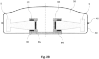
- the sealed housing 40 may be or may comprise a flexible casing. This is shown in Fig. 2A and Fig. 2B , of which the former shows the flexible casing 40 at nominal pressure (ambient case) and the latter shows the flexible casing 40 at high pressure (hot case). Individual elements of the bearing assembly may be omitted in these figures, for reasons of conciseness.
- the volume increase allowed for by the flexible casing 40 reduces the pressure increase that would result from the increase in temperature.
- reaction wheels are either completely sealed and evacuated or have casings with orifices that allow gas exchange with the environment. Consequently, the majority of reaction wheels operate under vacuum conditions in space.
- An advantage of this configuration is the complete absence of aerodynamic drag losses.
- Embodiments of the present disclosure rely on the presence of a gaseous atmosphere for the gas bearings, consequently drag losses are unavoidable. Under standard atmospheric conditions, these losses may exceed 100W for a large size wheel at full speed. These loss values are unacceptably high for space applications.
- the individual contributors to the total drag are the flywheel speed, the gas density and viscosity, the Reynolds number, and the flywheel shape. Each contributor can be tuned to reduce the total drag and thus the losses.
- the first contributor is the flywheel speed, which should be chosen low to minimize losses. Furthermore, a gas with a low dynamic viscosity should be chosen, for instance helium. There is a positive correlation between the gas pressure and drag losses, hence a pressure reduction will lead to lower drag losses. From first estimates, absolute gas pressures between ZOkPa and 50kPa would allow a significant loss reduction.
- the gas pressure in the sealed housing may be in the range from 10kPA to 80kPA, or preferably, in the range from 10kPA to .50kPA.
- a further aspect_ is the flow regime, which is characterized by the Reynolds number. A low Reynolds number corresponds to laminar flow, whereas a high Reynolds number leads to turbulent flow. For both low drag losses and low vibration emission, laminar flow should be preferred.
- the flywheel shape (or shape of applicable rotating element in general) can be optimized for minimal aerodynamic losses.
- Magnetic bearing reaction wheels conceptually require relatively large clearances between rotor and stator (approximately 0.5mm to 1mm). To avoid damage through rattling, magnetic bearing reaction wheels require a device that holds the rotor in a fixed position.
- Embodiments of the present disclosure have the advantage that the (static) gas bearing requires extremely small clearances of approximately 5 ⁇ m to 10 ⁇ m. These small clearances make damages due to launch vibration less likely, as the small gaps lead to comparably low relative speeds between rotor and stator.
- the contact area of the gas bearing between rotor and stator is very large, leading to low Hertzian contact pressures for the rotor-stator contact. It can be argued that both effects-small gaps and small Hertzian contact pressures-make an additional locking device potentially unnecessary, or at least very simple to implement.
- High reliability of spacecraft equipment can either be obtained through a very high reliability of its subcomponents, or when this is not possible, through redundancy.
- the contactless operation of the static gas bearing make a failure unlikely, given that the required supply gas pressure is provided.
- a potential single point of failure is the wheel housing, since a gas leak will eventually lead to a failure of the bearing system.
- the design of a leak-tight housing is a known problem and has been solved in different technology domains, and is therefore not of primary concern.
- micropump One subcomponent of the bearing assembly that may require special attention is the micropump. Its active elements, specifically the driven membrane and possibly the valve, are moving and have a non-negligible probability of failure. As noted above, the reliability of the valve can be greatly increased by replacing it with a solid-state valve (possibly at the cost of efficiency).
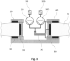
- the bearing assembly may comprise at least one second ultrasonic vibration pump (e.g., ultrasonic vibration pump 320 in Fig. 3 ) that is coupled to the gas bearing.
- This second ultrasonic vibration pump is also enclosed by the sealed housing (not shown in Fig. 3 ) and provides redundancy to the ultrasonic vibration pump 20.
- the second ultrasonic vibration pump(s) are coupled in parallel to the ultrasonic vibration pump 20.
- the second ultrasonic vibration pump(s) may have their own particle filter(s).
- the redundant pump e.g., ultrasonic vibration pump 320
- the redundant pump may be powered to provide the required supply pressure (cold redundancy).
- both pumps can be active at the same time with only 50% of the total required capacity (hot redundancy).
- additional ultrasonic vibration pumps may also be used to increase the achievable pressurization. This can be done by connecting (coupling) multiple pumps in series. In particular, if a single ultrasonic vibration pump is not sufficient for generating a desired pressurization, this can be addressed by providing a series connection of an appropriate number of ultrasonic vibration pumps. For providing redundancy, two or more series connections of ultrasonic vibration pumps may be provided in parallel.
- the bearing assembly may comprise at least one third ultrasonic vibration pump that is coupled to the gas bearing.
- This third ultrasonic vibration pump is also enclosed by the sealed housing and coupled in series with the (first) ultrasonic vibration pump.
- An emergency operation is defined as a failure to deliver the required gas pressure while the rotor is still rotating. In this case, a rotor-stator contact will occur, and both bearing friction as well as aerodynamic drag will eventually stop the rotor.
- the bearing should be designed to withstand a limited number of rotor touchdowns.
- the materials and surface treatment for both bearing and rotor should be chosen so that wear and the risk of fretting are kept to a minimum. Enabling other ways to dissipate the rotor's kinetic energy, for example by active braking through the drive system, will contribute to minimize the impact of a touchdown on the rotor-bearing system.
- the most likely event that leads to a sudden emergency operation is the loss of external power or a software glitch.
- the risk of a sudden external power loss can be mitigated by using the electrical power generated by the spinning rotor and use this power for the pump operation. Thanks to the moderate pump power requirements, this should be possible down to very low rotational speeds.
- the risk of a software glitch leading to a driver-induced pump failure can be mitigated by a simple, software-independent driver circuit.
- One of the main advantages of the proposed bearing assembly is its very low emission of vibrations, compared to state-of-the-art ball bearings.
- First estimates suggest a ten- to hundred-fold reduction in vibration emission, for example when the proposed bearing assembly is used for a reaction wheel.
- Reasons for these good results are the avoidance of a direct rotor-stator contact as well as the excellent damping provided by the gas film combined with the comparably low bearing stiffness.
- the low bearing stiffness on the other end might lead to critical speeds, hence an unbalance-induced resonance, in the operation range.
- Fig. 4 is a diagram showing bearing forces caused by unbalances as a function of wheel speed, for a flexible bearing.
- the location of the critical speed depends on the bearing stiffness.
- Graphs 410 and 420 indicate the bearing force as function of wheel speed for high and low bearing stiffness, respectively.
- the stiffness of a (static) gas bearing can be altered by changing the supply pressure. A higher supply pressure leads to a high bearing stiffness, conversely, lowering the supply pressure reduces the stiffness.
- the microvibration behavior can therefore be optimized by altering the pump power and hence the pump's outlet pressure with respect to the wheel speed.
- the pumps should generate high pressure for a high bearing stiffness (graph 410 in Fig. 4 ).
- the pump pressure should be lowered to follow the curve for low bearing stiffness (graph 520 in Fig. 4 ).
- the proposed method is not only limited to a simple switching between two pressures, but can involve a continuous pressure adaption, for instance through a look-up table.
- the proposed method has the advantage that the wheel (or rotatable element in general) can always be operated at the lowest vibration level.
- the bearing assembly may comprise a control unit for controlling operation of the ultrasonic vibration pump(s) (i.e., the (first) ultrasonic vibration pump 20), and possibly the second and/or third ultrasonic vibration pumps, if applicable), wherein the control unit is adapted to control a power (e.g., electric power) that is supplied to the pump(s) depending on a rotation speed of the rotatable element.
- the control unit may be implemented by a digital controller, microcontroller (microprocessor), or any suitable type of computer (computer processor), for example.
- the control unit may control the pressurization (e.g., pressure difference) that is applied by the ultrasonic vibration pump(s), in dependence on the rotation speed of the rotatable element.
- control unit may be adapted to control the power that is supplied to the ultrasonic vibration pump(s) in such manner that resonances between the gas bearing and the rotatable element (e.g., resonances in unbalance-induced bearing forces) are avoided.
- this may mean that the control unit is adapted to control the power that is supplied to the ultrasonic vibration pump in such manner that higher pressurization is applied for rotating speeds below a predefined threshold and lower pressurization is applied for rotating speeds above the predefined threshold.
- the respective amount of power to be supplied to the ultrasonic vibration pump(s) may be determined (e.g., by the control unit) based on the rotation speed of the rotatable element, for example using a lookup table.
- the predefined threshold may be chosen based on the occurrence of resonances in the bearing forces for high bearing stiffness and low bearing stiffness, typically between these resonances.
- Static air bearings can be manufactured in arbitrary shapes.
- a cylindrical radial bearing and a pair of flat bearing are used for axial rotor support, as shown in the example of Fig. 1 .
- the gas bearing of the bearing assembly may act as a radial bearing for the rotatable element (e.g., reaction wheel). This corresponds to gas bearing 15 in Fig. 1 .
- the bearing assembly may comprise one or more second gas bearings acting as axial bearings for the rotatable element. This would correspond to gas bearings 10 in Fig. 1 .
- the one or more second gas bearings are enclosed by the sealed housing.
- the second gas bearing may be provided with pressurized gas by the aforementioned ultrasonic vibration pump(s) or any additional ultrasonic vibration pump(s).
- the gas bearing of the bearing assembly may act (only) as an axial bearing for the rotatable element, or (only) as a radial bearing for the rotatable element.
- the gas bearing may be a spherical gas bearing.
- Fig. 5 shows another example of a flywheel configuration.
- the gas bearings 10, 15 are replaced by the (static) spherical gas bearing 510 that supports the rotor in axial and radial direction, as well as rotation about the flywheel principal axis of inertia (vertical, dashed line) around center point 70.
- flywheel swiveling is allowed for.
- the spherical gas bearing 510 is supported by support structure 565.
- elements of the bearing assembly 2 of Fig. 5 may be identical to those of the bearing assembly 1 of Fig. 1 .
- the pump and pipes may be omitted in Fig.
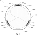
- FIG. 6 shows a bearing assembly 3 for a rotating sphere (e.g., reaction sphere) 605 instead of a flywheel.
- a rotating sphere e.g., reaction sphere
- the sealed housing 640 has a shape commensurable with the shape of the rotating sphere 605. Pumps, pipes, etc. may be omitted from Fig. 6 for reasons of conciseness and may correspond to those shown in Fig. 1 .
- One advantage of this implementation is the ability to accelerate and decelerate the sphere in any direction, allowing to control the attitude of a spacecraft in any direction with a single device.
- the concept of a drive and bearing system for a reaction sphere using magnetic forces is described in US 2014/0209751 A1 .
- the present embodiment has the advantage of its simplicity, lightness and energy efficiency. Furthermore, it allows for a large degree of freedom in design, since the choice of material for the sphere is almost completely unconstrained.
- the specific implementation of the motor for driving the reaction sphere is beyond the scope of the present disclosure. Motors feasible for this purpose are described for example in patent document US 2014/209751 A1 and in L. Rossini, O. Chételat, E. Onillon, Y.
- reaction wheel assembly for a spacecraft, comprising a reaction wheel and a bearing assembly as described above (e.g., the bearing assembly of Fig. 1 ) for stabilizing rotation of the reaction wheel.
- control motion gyroscope assembly for a spacecraft, comprising a control motion gyroscope and a bearing assembly as described above (e.g., the bearing assembly 2 of Fig. 5 ) for stabilizing rotation of the control motion gyroscope.
- reaction sphere assembly for a spacecraft, comprising a reaction sphere and a bearing assembly as described above (e.g., the bearing assembly 3 of Fig. 6 ) for stabilizing rotation of the reaction sphere.
- reaction wheel or flywheel
- the prototype is designed to deliver an angular momentum of 24Nms at 6000rpm, which is in line with the performance needs of typical mid-to-large size spacecraft platforms, used for example for Earth observation, astronomy or navigation.
- a first test phase the rotor has been operated up to a maximum of 5,800rpm to study the general characteristics of the wheel.
- the functionality of the micropumps has been tested and verified.
- the axial bearing is pressurized with 1.2bar, whereas the radial bearing is pressurized with 0.6bar of pressurized air.
- the fly wheel has been accelerated using the built-in commercial brushless DC motor. When a speed of approximately 5,800rpm had been reached, the motor had been switched off and the flywheel had been let to coast-down using the atmospheric drag acting on the fly-wheel as well as the drag within the air bearings themselves.
- the test was primarily used to verify that the air bearings are capable of carrying the load of the rotor and that there is no physical contact between any solid parts. Since there was no audible noise during the coast down (e.g., no grinding, no clicking, not even any perceivable noise due to air swirls), the load-carrying function of the bearings has been demonstrated.
- microvibration Another point of interest is microvibration.
- the prototype In order to characterize the vibrations emitted during operation of the air bearing, the prototype has been installed on a 6-axis dynamometer. This device is capable of measuring very small forces and torques with high precision and is standard for microvibration testing of reaction wheels. It has been found that the overall level of emitted vibration is very low. Along the x-axis, i.e., in radial direction, vibrations are dominated by the static unbalance of the rotor. A measured force of about 1N at 5,800rpm corresponds to an unbalance of 0.3gcm, which is a typical value for balanced reaction wheel flywheels. More importantly it has further been found that there is no other major noise source within the spectrum of the recorded microvibration.
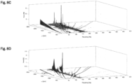
- Fig. 8A and Fig. 8B show the microvibration spectrum of a reaction wheel using the bearing assembly according to embodiments of the disclosure, in radial direction (x-axis) and axial direction (z-axis), respectively.
- Fig. 8C and Fig. 8D show the typical microvibration spectrum in radial direction (x-axis) and axial direction (z-axis) for a conventional reaction wheel of similar size as the air bearing prototype, using ball bearings.
- graph 910 indicates noise levels along the radial direction (x- and y-axes)
- graph 920 indicates the noise level in the axial direction (z-axis).
- graphs 930 and 940 indicate noise levels along the radial direction (x- and y-axes), and in the axial direction (z-axis), respectively.
- vibration levels of the air bearing according to embodiments of the disclosure are by a factor of 10 to 30 below the ball bearing for radial directions (x- and y-axes) and by a factor of 5 to 20 below for the axial direction (z-axis).
- An example implementation relates to a bearing system, comprising: a static gas bearing with up to three degrees of freedom, allowing the rotation or translation of an object with low friction.
- the gas bearing is connected through pipes or tubes to the outlet of an ultrasonic membrane pump.
- This pump is characterized by an actuated membrane vibrating at an inaudible, ultrasonic frequency.
- the proposed pump generates a standing wave of gas pressure in a cavity.
- the pump's gas inlet is located at a gas pressure node, whereas the pump's outlet is located at a pressure antinode.
- a check valve is required at the pump's outlet. This valve can be realized using moving parts, or can be of solid state.
- the pump's inlet features a filter that protects the pump from particles or debris.
- the gas bearing assembly and the pump are enclosed in a hermetically sealed housing.
- the housing is filled with a pressurized gas to enable operation of the pump and the gas bearing.
- the housing is split to allow the assembly of the components. After assembly, the split housing is closed and sealed.
- the sealing system may for instance be performed by a flange with an O-Ring, a soldered or welded connection, or another sealing method.
- the housing may contain hermetically sealed feedthroughs for electrical connections. Temperature changes can lead to significant, potentially unwanted changes in the absolute gas pressure inside the housing. These changes can be reduced by designing the pressurized vessel with a flexible housing, allowing a volume increase and thus lower absolute gas pressure changes.
- pump redundancy may be achieved by connecting (coupling) multiple pumps in parallel.
- Another example implementation relates to a method for reducing the vibration signature of a rotating object in gas bearings by changing the bearing stiffness.
- the positive correlation between the stiffness of a static gas bearing and the gas supply pressure provided by the pump can be harnessed to reduce the vibration emission caused by unbalance.
- the mass of the rotating object and the bearing stiffness resonances causing large rotor deflections and bearing forces may occur.
- the proposed method defines an optimal bearing stiffness (and hence pressure) level for any rotational speed. These optimal pressure levels can be determined using analysis or tests and then stored in a look-up table. For each speed, the digital controller, microcontroller (microprocessor), computer (computer processor) or control unit in general may feed the optimal pump power and thus pressure levels to the ultrasonic pump.
- control units or blocks described throughout the disclosure may be implemented by a digital controller, microcontroller (microprocessor), computer, computer processor or respective computer processors, or the like.
Landscapes
- Engineering & Computer Science (AREA)
- General Engineering & Computer Science (AREA)
- Mechanical Engineering (AREA)
- Remote Sensing (AREA)
- Aviation & Aerospace Engineering (AREA)
- Magnetic Bearings And Hydrostatic Bearings (AREA)
- Rolling Contact Bearings (AREA)
Claims (15)
- Lagerbaugruppe zum Stabilisieren der Rotation eines rotationsfähigen Elementes (5) unter Vakuumbedingungen, wobei die Lagerbaugruppe Folgendes umfasst:ein statisches Luftlager (10, 15), das als Lager für das rotationsfähige Element (5) dient;eine Ultraschall-Vibrationspumpe (20), die mit dem statischen Luftlager (10, 15) gekoppelt ist, zum Bereitstellen von unter Druck gesetztem Gas für das Luftlager (10, 15) undein abgedichtetes Gehäuse (40), das das statische Luftlager (10, 15) und die Ultraschall-Vibrationspumpe (20) umschließt;wobei die Ultraschall-Vibrationspumpe (20) einen Pumpeneinlass umfasst, durch den Gas (50), das im abgedichteten Gehäuse (40) umschlossen ist, in die Ultraschall-Vibrationspumpe (20) eintreten kann.
- Lagerbaugruppe nach Anspruch 1, die ferner eine Steuereinheit zum Steuern des Betriebes der Ultraschall-Vibrationspumpe (20) umfasst,
wobei die Steuereinheit ausgelegt ist, eine Leistung, die der Pumpe zugeführt wird, abhängig von einer Drehzahl des rotationsfähigen Elementes (5) zu steuern. - Lagerbaugruppe nach Anspruch 2, wobei die Steuereinheit ausgelegt ist, die Leistung, die der Ultraschall-Vibrationspumpe (20) zugeführt wird, auf solche Weise zu steuern, dass höhere Druckbeaufschlagung für Drehzahlen unterhalb einer vordefinierten Schwelle angewandt wird und niedrigere Druckbeaufschlagung für Drehzahlen oberhalb der vordefinierten Schwelle angewandt wird.
- Lagerbaugruppe nach Anspruch 2 oder 3, wobei die Leistung, die der Ultraschall-Vibrationspumpe (20) zuzuführen ist, basierend auf der Drehzahl des rotationsfähigen Elementes (5) unter Verwendung einer Umsetzungstabelle ermittelt wird.
- Lagerbaugruppe nach irgendeinem der vorhergehenden Ansprüche, wobei die Ultraschall-Vibrationspumpe (20) eine Ultraschall-Membranpumpe ist.
- Lagerbaugruppe nach irgendeinem der vorhergehenden Ansprüche,wobei die Ultraschall-Vibrationspumpe (20) ein Festkörperventil umfasst und/oderwobei der Pumpeneinlass der Ultraschall-Vibrationspumpe (20) mit einem Partikelfilter gekoppelt ist.
- Lagerbaugruppe nach irgendeinem der vorhergehenden Ansprüche, wobei das statische Luftlager (10, 15) als Radiallager für das rotationsfähige Element (5) wirkt.
- Lagerbaugruppe nach irgendeinem der vorhergehenden Ansprüche, die ferner ein oder mehrere zweite statische Luftlager (10, 15) umfasst, die als Axiallager für das rotationsfähige Element (5) wirken,
wobei das einer oder die mehreren zweiten statischen Luftlager (10, 15) durch das abgedichtete Gehäuse (40) umschlossen sind. - Lagerbaugruppe nach irgendeinem der Ansprüche 1 bis 6, wobei das statische Luftlager (10, 15) ein statisches Pendel-Luftlager ist.
- Lagerbaugruppe nach irgendeinem der vorhergehenden Ansprüche, die ferner mindestens eine zweite Ultraschall-Vibrationspumpe (20, 320) umfasst, die mit dem statischen Luftlager (10, 15) gekoppelt ist,
wobei die mindestens eine zweite Ultraschall-Vibrationspumpe (20, 320) durch das abgedichtete Gehäuse (40) umschlossen und parallel mit der Ultraschall-Vibrationspumpe (20) gekoppelt ist. - Lagerbaugruppe nach irgendeinem der vorhergehenden Ansprüche, die ferner mindestens eine dritte Ultraschall-Vibrationspumpe umfasst, die mit dem statischen Luftlager (10, 15) gekoppelt ist,
wobei die mindestens eine dritte Ultraschall-Vibrationspumpe durch das abgedichtete Gehäuse (40) umschlossen und mit der Ultraschall-Vibrationspumpe (20) in Reihe gekoppelt ist. - Lagerbaugruppe nach irgendeinem der vorhergehenden Ansprüche, wobei ein Gasdruck im abgedichteten Gehäuse (40) im Bereich von 10 kPa bis 80 kPa liegt.
- Lagerbaugruppe nach irgendeinem der vorhergehenden Ansprüche,wobei das abgedichtete Gehäuse (40) eine flexible Umhüllung ist und/oderwobei das abgedichtete Gehäuse (40) eine abgedichtete Verbindung umfasst.
- Lagerbaugruppe nach irgendeinem der vorhergehenden Ansprüche, wobei das rotationsfähige Element (5) eines von Folgendem ist:ein Reaktionsrad für ein Raumfahrzeug;ein Momentenkreisel für ein Raumfahrzeug undeine Reaktionssphäre für ein Raumfahrzeug.
- Reaktionsradbaugruppe für ein Raumfahrzeug, wobei die Reaktionsradbaugruppe Folgendes umfasst:ein Reaktionsrad unddie Lagerbaugruppe nach irgendeinem der Ansprüche 1 bis 13 zum Stabilisieren der Rotation des Reaktionsrades.
Priority Applications (4)
| Application Number | Priority Date | Filing Date | Title |
|---|---|---|---|
| ES20210368T ES2980243T3 (es) | 2020-11-27 | 2020-11-27 | Sistema de cojinete de gas |
| EP20210368.5A EP4006367B1 (de) | 2020-11-27 | 2020-11-27 | Gaslagersystem |
| US17/454,780 US12077322B2 (en) | 2020-11-27 | 2021-11-12 | Gas bearing system |
| CA3139423A CA3139423C (en) | 2020-11-27 | 2021-11-18 | GAS BEARING SYSTEM |
Applications Claiming Priority (1)
| Application Number | Priority Date | Filing Date | Title |
|---|---|---|---|
| EP20210368.5A EP4006367B1 (de) | 2020-11-27 | 2020-11-27 | Gaslagersystem |
Publications (3)
| Publication Number | Publication Date |
|---|---|
| EP4006367A1 EP4006367A1 (de) | 2022-06-01 |
| EP4006367C0 EP4006367C0 (de) | 2024-05-22 |
| EP4006367B1 true EP4006367B1 (de) | 2024-05-22 |
Family
ID=73642704
Family Applications (1)
| Application Number | Title | Priority Date | Filing Date |
|---|---|---|---|
| EP20210368.5A Active EP4006367B1 (de) | 2020-11-27 | 2020-11-27 | Gaslagersystem |
Country Status (4)
| Country | Link |
|---|---|
| US (1) | US12077322B2 (de) |
| EP (1) | EP4006367B1 (de) |
| CA (1) | CA3139423C (de) |
| ES (1) | ES2980243T3 (de) |
Families Citing this family (2)
| Publication number | Priority date | Publication date | Assignee | Title |
|---|---|---|---|---|
| CN120780045A (zh) * | 2025-06-24 | 2025-10-14 | 中国机械总院集团青岛分院有限公司 | 一种抑制转子振动的主动调控方法及系统 |
| CN121990182B (zh) * | 2026-04-10 | 2026-06-09 | 北京航空航天大学 | 一种基于执行器动态的微纳卫星多约束精细控制方法 |
Family Cites Families (15)
| Publication number | Priority date | Publication date | Assignee | Title |
|---|---|---|---|---|
| JPS5292048A (en) | 1976-01-28 | 1977-08-03 | Agency Of Ind Science & Technol | Porous static pressure gas bearing |
| JPH086748B2 (ja) | 1990-04-19 | 1996-01-29 | キヤノン株式会社 | 多孔質静圧気体軸受の製造方法 |
| GB0612979D0 (en) | 2006-06-30 | 2006-08-09 | Renishaw Plc | Gas bearing fabrication method |
| US20080099626A1 (en) * | 2006-10-27 | 2008-05-01 | Goodrich Corporation | Reconfigurable reaction wheel for spacecraft |
| GB0804739D0 (en) | 2008-03-14 | 2008-04-16 | The Technology Partnership Plc | Pump |
| EP2306019A4 (de) | 2008-05-30 | 2014-10-15 | Murata Manufacturing Co | Piezoelektrisches mikrogebläse |
| EP2312158B1 (de) | 2008-06-05 | 2016-04-27 | Murata Manufacturing Co. Ltd. | Piezoelektrisches mikrogebläse |
| GB2467168B (en) | 2009-01-26 | 2011-03-16 | Air Bearings Ltd | Gas bearing and method of manufacturing the same |
| CN102460910A (zh) * | 2009-05-15 | 2012-05-16 | 发现技术国际股份有限公司 | 具有超声波非接触轴承的电马达 |
| US9475592B2 (en) | 2013-01-31 | 2016-10-25 | Northrop Grumman Systems Corporation | Reaction sphere for stabilization and control in three axes |
| GB201322103D0 (en) | 2013-12-13 | 2014-01-29 | The Technology Partnership Plc | Fluid pump |
| US20160363165A1 (en) | 2015-06-09 | 2016-12-15 | Hiwin Mikrosystem Corp. | Air bearing structure |
| GB201517770D0 (en) * | 2015-10-08 | 2015-11-25 | Birmingham High Performance Turbomachinery Ltd | Improvements in or relating to gas bearings |
| US10215223B2 (en) * | 2016-09-29 | 2019-02-26 | Metal Industries Research&Development Centre | Non-contact bearing |
| GB2577710B (en) | 2018-10-03 | 2022-12-14 | Lee Ventus Ltd | Methods and devices for driving a piezoelectric pump |
-
2020
- 2020-11-27 EP EP20210368.5A patent/EP4006367B1/de active Active
- 2020-11-27 ES ES20210368T patent/ES2980243T3/es active Active
-
2021
- 2021-11-12 US US17/454,780 patent/US12077322B2/en active Active
- 2021-11-18 CA CA3139423A patent/CA3139423C/en active Active
Also Published As
| Publication number | Publication date |
|---|---|
| US12077322B2 (en) | 2024-09-03 |
| EP4006367C0 (de) | 2024-05-22 |
| US20220170509A1 (en) | 2022-06-02 |
| ES2980243T3 (es) | 2024-09-30 |
| EP4006367A1 (de) | 2022-06-01 |
| CA3139423C (en) | 2025-09-09 |
| CA3139423A1 (en) | 2022-05-27 |
Similar Documents
| Publication | Publication Date | Title |
|---|---|---|
| US9255495B2 (en) | Magnetically-coupled damper for turbomachinery | |
| US12077322B2 (en) | Gas bearing system | |
| Ahrens et al. | Performance of a magnetically suspended flywheel energy storage device | |
| CN109477511B (zh) | 集成式轴颈轴承 | |
| JP2005532516A (ja) | 永久磁石を用いた、回転子軸受システム用のスラスト荷重緩和装置 | |
| EP2388465A1 (de) | Achsladevorrichtung und Verfahren für magnetisch unterstützte Rotorsysteme | |
| US4988906A (en) | Magnetic bearing assembly | |
| CN104204633A (zh) | 磁流体密封件 | |
| Hawkins et al. | Design of a compact magnetically levitated blower for space applications | |
| Flint et al. | Active/passive counter-force vibration control and isolation systems | |
| TW202415860A (zh) | 高壓循環熱泵之無摩擦設計 | |
| US7086648B1 (en) | Acoustic seal | |
| Kasarda et al. | An experimental investigation of the effect of an active magnetic damper on reducing subsynchronous vibrations in rotating machinery | |
| Hawkins et al. | Design of a compact magnetically levitated blower for space applications | |
| Hoang et al. | Performance demonstration of flexible advanced loop heat pipe for across-gimbal cryocooling | |
| Chen et al. | Development of a Miniature, Reliable Ammonia Pump for Spaceborne Two-Phase Pumped Loops | |
| Sindlinger | Magnetic bearing momentum wheels with vernier gimballing capability for 3-axis active attitude control and energy storage | |
| Sahinkaya et al. | Bias current optimization and fuzzy controllers for magnetic bearings in turbo molecular pumps | |
| Hawkins et al. | Random Vibration Simulation and Testing of a Compact, Magnetic Bearing Supported Blower for Space Applications | |
| JP2013150499A (ja) | 電力貯蔵装置の制振構造 | |
| Wimer et al. | Dynamic modeling of an integrated flywheel energy storage system | |
| Bennett et al. | Vibration Isolation, Steering, and Suppression Mechanism for Space-Based Sensors | |
| Nye | Active control of bearing preload using piezoelectric translators | |
| Barillot et al. | Tough Precision Piezoelectric Motors for Space Applications | |
| Heshmat et al. | On the Development of an Oil-free, High-speed and High-temperature Turboalternator |
Legal Events
| Date | Code | Title | Description |
|---|---|---|---|
| PUAI | Public reference made under article 153(3) epc to a published international application that has entered the european phase |
Free format text: ORIGINAL CODE: 0009012 |
|
| STAA | Information on the status of an ep patent application or granted ep patent |
Free format text: STATUS: THE APPLICATION HAS BEEN PUBLISHED |
|
| AK | Designated contracting states |
Kind code of ref document: A1 Designated state(s): AL AT BE BG CH CY CZ DE DK EE ES FI FR GB GR HR HU IE IS IT LI LT LU LV MC MK MT NL NO PL PT RO RS SE SI SK SM TR |
|
| STAA | Information on the status of an ep patent application or granted ep patent |
Free format text: STATUS: REQUEST FOR EXAMINATION WAS MADE |
|
| STAA | Information on the status of an ep patent application or granted ep patent |
Free format text: STATUS: EXAMINATION IS IN PROGRESS |
|
| 17P | Request for examination filed |
Effective date: 20221129 |
|
| RBV | Designated contracting states (corrected) |
Designated state(s): AL AT BE BG CH CY CZ DE DK EE ES FI FR GB GR HR HU IE IS IT LI LT LU LV MC MK MT NL NO PL PT RO RS SE SI SK SM TR |
|
| 17Q | First examination report despatched |
Effective date: 20221221 |
|
| GRAP | Despatch of communication of intention to grant a patent |
Free format text: ORIGINAL CODE: EPIDOSNIGR1 |
|
| STAA | Information on the status of an ep patent application or granted ep patent |
Free format text: STATUS: GRANT OF PATENT IS INTENDED |
|
| INTG | Intention to grant announced |
Effective date: 20231215 |
|
| GRAS | Grant fee paid |
Free format text: ORIGINAL CODE: EPIDOSNIGR3 |
|
| GRAA | (expected) grant |
Free format text: ORIGINAL CODE: 0009210 |
|
| STAA | Information on the status of an ep patent application or granted ep patent |
Free format text: STATUS: THE PATENT HAS BEEN GRANTED |
|
| AK | Designated contracting states |
Kind code of ref document: B1 Designated state(s): AL AT BE BG CH CY CZ DE DK EE ES FI FR GB GR HR HU IE IS IT LI LT LU LV MC MK MT NL NO PL PT RO RS SE SI SK SM TR |
|
| REG | Reference to a national code |
Ref country code: GB Ref legal event code: FG4D |
|
| REG | Reference to a national code |
Ref country code: CH Ref legal event code: EP |
|
| REG | Reference to a national code |
Ref country code: DE Ref legal event code: R096 Ref document number: 602020031228 Country of ref document: DE |
|
| REG | Reference to a national code |
Ref country code: IE Ref legal event code: FG4D |
|
| U01 | Request for unitary effect filed |
Effective date: 20240621 |
|
| U07 | Unitary effect registered |
Designated state(s): AT BE BG DE DK EE FI FR IT LT LU LV MT NL PT SE SI Effective date: 20240702 |
|
| REG | Reference to a national code |
Ref country code: ES Ref legal event code: FG2A Ref document number: 2980243 Country of ref document: ES Kind code of ref document: T3 Effective date: 20240930 |
|
| PG25 | Lapsed in a contracting state [announced via postgrant information from national office to epo] |
Ref country code: IS Free format text: LAPSE BECAUSE OF FAILURE TO SUBMIT A TRANSLATION OF THE DESCRIPTION OR TO PAY THE FEE WITHIN THE PRESCRIBED TIME-LIMIT Effective date: 20240922 |
|
| PG25 | Lapsed in a contracting state [announced via postgrant information from national office to epo] |
Ref country code: HR Free format text: LAPSE BECAUSE OF FAILURE TO SUBMIT A TRANSLATION OF THE DESCRIPTION OR TO PAY THE FEE WITHIN THE PRESCRIBED TIME-LIMIT Effective date: 20240522 |
|
| PG25 | Lapsed in a contracting state [announced via postgrant information from national office to epo] |
Ref country code: GR Free format text: LAPSE BECAUSE OF FAILURE TO SUBMIT A TRANSLATION OF THE DESCRIPTION OR TO PAY THE FEE WITHIN THE PRESCRIBED TIME-LIMIT Effective date: 20240823 |
|
| PG25 | Lapsed in a contracting state [announced via postgrant information from national office to epo] |
Ref country code: PL Free format text: LAPSE BECAUSE OF FAILURE TO SUBMIT A TRANSLATION OF THE DESCRIPTION OR TO PAY THE FEE WITHIN THE PRESCRIBED TIME-LIMIT Effective date: 20240522 |
|
| PG25 | Lapsed in a contracting state [announced via postgrant information from national office to epo] |
Ref country code: PL Free format text: LAPSE BECAUSE OF FAILURE TO SUBMIT A TRANSLATION OF THE DESCRIPTION OR TO PAY THE FEE WITHIN THE PRESCRIBED TIME-LIMIT Effective date: 20240522 Ref country code: NO Free format text: LAPSE BECAUSE OF FAILURE TO SUBMIT A TRANSLATION OF THE DESCRIPTION OR TO PAY THE FEE WITHIN THE PRESCRIBED TIME-LIMIT Effective date: 20240822 Ref country code: IS Free format text: LAPSE BECAUSE OF FAILURE TO SUBMIT A TRANSLATION OF THE DESCRIPTION OR TO PAY THE FEE WITHIN THE PRESCRIBED TIME-LIMIT Effective date: 20240922 Ref country code: HR Free format text: LAPSE BECAUSE OF FAILURE TO SUBMIT A TRANSLATION OF THE DESCRIPTION OR TO PAY THE FEE WITHIN THE PRESCRIBED TIME-LIMIT Effective date: 20240522 Ref country code: GR Free format text: LAPSE BECAUSE OF FAILURE TO SUBMIT A TRANSLATION OF THE DESCRIPTION OR TO PAY THE FEE WITHIN THE PRESCRIBED TIME-LIMIT Effective date: 20240823 Ref country code: RS Free format text: LAPSE BECAUSE OF FAILURE TO SUBMIT A TRANSLATION OF THE DESCRIPTION OR TO PAY THE FEE WITHIN THE PRESCRIBED TIME-LIMIT Effective date: 20240822 |
|
| U20 | Renewal fee for the european patent with unitary effect paid |
Year of fee payment: 5 Effective date: 20241126 |
|
| PG25 | Lapsed in a contracting state [announced via postgrant information from national office to epo] |
Ref country code: CZ Free format text: LAPSE BECAUSE OF FAILURE TO SUBMIT A TRANSLATION OF THE DESCRIPTION OR TO PAY THE FEE WITHIN THE PRESCRIBED TIME-LIMIT Effective date: 20240522 |
|
| PG25 | Lapsed in a contracting state [announced via postgrant information from national office to epo] |
Ref country code: SK Free format text: LAPSE BECAUSE OF FAILURE TO SUBMIT A TRANSLATION OF THE DESCRIPTION OR TO PAY THE FEE WITHIN THE PRESCRIBED TIME-LIMIT Effective date: 20240522 Ref country code: RO Free format text: LAPSE BECAUSE OF FAILURE TO SUBMIT A TRANSLATION OF THE DESCRIPTION OR TO PAY THE FEE WITHIN THE PRESCRIBED TIME-LIMIT Effective date: 20240522 |
|
| PG25 | Lapsed in a contracting state [announced via postgrant information from national office to epo] |
Ref country code: SM Free format text: LAPSE BECAUSE OF FAILURE TO SUBMIT A TRANSLATION OF THE DESCRIPTION OR TO PAY THE FEE WITHIN THE PRESCRIBED TIME-LIMIT Effective date: 20240522 |
|
| PG25 | Lapsed in a contracting state [announced via postgrant information from national office to epo] |
Ref country code: SM Free format text: LAPSE BECAUSE OF FAILURE TO SUBMIT A TRANSLATION OF THE DESCRIPTION OR TO PAY THE FEE WITHIN THE PRESCRIBED TIME-LIMIT Effective date: 20240522 Ref country code: SK Free format text: LAPSE BECAUSE OF FAILURE TO SUBMIT A TRANSLATION OF THE DESCRIPTION OR TO PAY THE FEE WITHIN THE PRESCRIBED TIME-LIMIT Effective date: 20240522 Ref country code: RO Free format text: LAPSE BECAUSE OF FAILURE TO SUBMIT A TRANSLATION OF THE DESCRIPTION OR TO PAY THE FEE WITHIN THE PRESCRIBED TIME-LIMIT Effective date: 20240522 Ref country code: CZ Free format text: LAPSE BECAUSE OF FAILURE TO SUBMIT A TRANSLATION OF THE DESCRIPTION OR TO PAY THE FEE WITHIN THE PRESCRIBED TIME-LIMIT Effective date: 20240522 |
|
| REG | Reference to a national code |
Ref country code: DE Ref legal event code: R097 Ref document number: 602020031228 Country of ref document: DE |
|
| PLBE | No opposition filed within time limit |
Free format text: ORIGINAL CODE: 0009261 |
|
| STAA | Information on the status of an ep patent application or granted ep patent |
Free format text: STATUS: NO OPPOSITION FILED WITHIN TIME LIMIT |
|
| 26N | No opposition filed |
Effective date: 20250225 |
|
| PG25 | Lapsed in a contracting state [announced via postgrant information from national office to epo] |
Ref country code: MC Free format text: LAPSE BECAUSE OF FAILURE TO SUBMIT A TRANSLATION OF THE DESCRIPTION OR TO PAY THE FEE WITHIN THE PRESCRIBED TIME-LIMIT Effective date: 20240522 |
|
| PG25 | Lapsed in a contracting state [announced via postgrant information from national office to epo] |
Ref country code: IE Free format text: LAPSE BECAUSE OF NON-PAYMENT OF DUE FEES Effective date: 20241127 |
|
| REG | Reference to a national code |
Ref country code: CH Ref legal event code: U11 Free format text: ST27 STATUS EVENT CODE: U-0-0-U10-U11 (AS PROVIDED BY THE NATIONAL OFFICE) Effective date: 20251201 |
|
| U20 | Renewal fee for the european patent with unitary effect paid |
Year of fee payment: 6 Effective date: 20251127 |
|
| PGFP | Annual fee paid to national office [announced via postgrant information from national office to epo] |
Ref country code: GB Payment date: 20251121 Year of fee payment: 6 |
|
| PGFP | Annual fee paid to national office [announced via postgrant information from national office to epo] |
Ref country code: CH Payment date: 20251201 Year of fee payment: 6 |
|
| PGFP | Annual fee paid to national office [announced via postgrant information from national office to epo] |
Ref country code: ES Payment date: 20251229 Year of fee payment: 6 |
|
| PG25 | Lapsed in a contracting state [announced via postgrant information from national office to epo] |
Ref country code: HU Free format text: LAPSE BECAUSE OF FAILURE TO SUBMIT A TRANSLATION OF THE DESCRIPTION OR TO PAY THE FEE WITHIN THE PRESCRIBED TIME-LIMIT; INVALID AB INITIO Effective date: 20201127 |
|
| PG25 | Lapsed in a contracting state [announced via postgrant information from national office to epo] |
Ref country code: CY Free format text: LAPSE BECAUSE OF FAILURE TO SUBMIT A TRANSLATION OF THE DESCRIPTION OR TO PAY THE FEE WITHIN THE PRESCRIBED TIME-LIMIT; INVALID AB INITIO Effective date: 20201127 |
|
| PG25 | Lapsed in a contracting state [announced via postgrant information from national office to epo] |
Ref country code: TR Free format text: LAPSE BECAUSE OF FAILURE TO SUBMIT A TRANSLATION OF THE DESCRIPTION OR TO PAY THE FEE WITHIN THE PRESCRIBED TIME-LIMIT Effective date: 20240522 |