EP4006385A1 - Elektrische antriebsanordnung eines trockendifferenzials und mit neuer energie gespeistes fahrzeug - Google Patents
Elektrische antriebsanordnung eines trockendifferenzials und mit neuer energie gespeistes fahrzeug Download PDFInfo
- Publication number
- EP4006385A1 EP4006385A1 EP19943958.9A EP19943958A EP4006385A1 EP 4006385 A1 EP4006385 A1 EP 4006385A1 EP 19943958 A EP19943958 A EP 19943958A EP 4006385 A1 EP4006385 A1 EP 4006385A1
- Authority
- EP
- European Patent Office
- Prior art keywords
- differential
- reducer
- housing
- electric drive
- drive assembly
- Prior art date
- Legal status (The legal status is an assumption and is not a legal conclusion. Google has not performed a legal analysis and makes no representation as to the accuracy of the status listed.)
- Withdrawn
Links
- 239000003638 chemical reducing agent Substances 0.000 claims abstract description 29
- 238000007789 sealing Methods 0.000 abstract description 6
- 230000033001 locomotion Effects 0.000 abstract description 4
- 230000003068 static effect Effects 0.000 abstract description 3
- 239000003921 oil Substances 0.000 description 15
- 230000005540 biological transmission Effects 0.000 description 2
- 238000010586 diagram Methods 0.000 description 1
- 239000010687 lubricating oil Substances 0.000 description 1
- 230000007246 mechanism Effects 0.000 description 1
- 238000006467 substitution reaction Methods 0.000 description 1
Images

Classifications
-
- F—MECHANICAL ENGINEERING; LIGHTING; HEATING; WEAPONS; BLASTING
- F16—ENGINEERING ELEMENTS AND UNITS; GENERAL MEASURES FOR PRODUCING AND MAINTAINING EFFECTIVE FUNCTIONING OF MACHINES OR INSTALLATIONS; THERMAL INSULATION IN GENERAL
- F16H—GEARING
- F16H48/00—Differential gearings
- F16H48/06—Differential gearings with gears having orbital motion
- F16H48/08—Differential gearings with gears having orbital motion comprising bevel gears
-
- F—MECHANICAL ENGINEERING; LIGHTING; HEATING; WEAPONS; BLASTING
- F16—ENGINEERING ELEMENTS AND UNITS; GENERAL MEASURES FOR PRODUCING AND MAINTAINING EFFECTIVE FUNCTIONING OF MACHINES OR INSTALLATIONS; THERMAL INSULATION IN GENERAL
- F16H—GEARING
- F16H48/00—Differential gearings
- F16H48/38—Constructional details
-
- B—PERFORMING OPERATIONS; TRANSPORTING
- B60—VEHICLES IN GENERAL
- B60K—ARRANGEMENT OR MOUNTING OF PROPULSION UNITS OR OF TRANSMISSIONS IN VEHICLES; ARRANGEMENT OR MOUNTING OF PLURAL DIVERSE PRIME-MOVERS IN VEHICLES; AUXILIARY DRIVES FOR VEHICLES; INSTRUMENTATION OR DASHBOARDS FOR VEHICLES; ARRANGEMENTS IN CONNECTION WITH COOLING, AIR INTAKE, GAS EXHAUST OR FUEL SUPPLY OF PROPULSION UNITS IN VEHICLES
- B60K1/00—Arrangement or mounting of electrical propulsion units
-
- B—PERFORMING OPERATIONS; TRANSPORTING
- B60—VEHICLES IN GENERAL
- B60K—ARRANGEMENT OR MOUNTING OF PROPULSION UNITS OR OF TRANSMISSIONS IN VEHICLES; ARRANGEMENT OR MOUNTING OF PLURAL DIVERSE PRIME-MOVERS IN VEHICLES; AUXILIARY DRIVES FOR VEHICLES; INSTRUMENTATION OR DASHBOARDS FOR VEHICLES; ARRANGEMENTS IN CONNECTION WITH COOLING, AIR INTAKE, GAS EXHAUST OR FUEL SUPPLY OF PROPULSION UNITS IN VEHICLES
- B60K17/00—Arrangement or mounting of transmissions in vehicles
- B60K17/04—Arrangement or mounting of transmissions in vehicles characterised by arrangement, location or kind of gearing
- B60K17/16—Arrangement or mounting of transmissions in vehicles characterised by arrangement, location or kind of gearing of differential gearing
- B60K17/165—Arrangement or mounting of transmissions in vehicles characterised by arrangement, location or kind of gearing of differential gearing provided between independent half axles
-
- F—MECHANICAL ENGINEERING; LIGHTING; HEATING; WEAPONS; BLASTING
- F16—ENGINEERING ELEMENTS AND UNITS; GENERAL MEASURES FOR PRODUCING AND MAINTAINING EFFECTIVE FUNCTIONING OF MACHINES OR INSTALLATIONS; THERMAL INSULATION IN GENERAL
- F16H—GEARING
- F16H57/00—General details of gearing
- F16H57/02—Gearboxes; Mounting gearing therein
- F16H57/029—Gearboxes; Mounting gearing therein characterised by means for sealing the gearboxes, e.g. to improve airtightness
-
- F—MECHANICAL ENGINEERING; LIGHTING; HEATING; WEAPONS; BLASTING
- F16—ENGINEERING ELEMENTS AND UNITS; GENERAL MEASURES FOR PRODUCING AND MAINTAINING EFFECTIVE FUNCTIONING OF MACHINES OR INSTALLATIONS; THERMAL INSULATION IN GENERAL
- F16H—GEARING
- F16H57/00—General details of gearing
- F16H57/02—Gearboxes; Mounting gearing therein
- F16H57/037—Gearboxes for accommodating differential gearings
-
- B—PERFORMING OPERATIONS; TRANSPORTING
- B60—VEHICLES IN GENERAL
- B60K—ARRANGEMENT OR MOUNTING OF PROPULSION UNITS OR OF TRANSMISSIONS IN VEHICLES; ARRANGEMENT OR MOUNTING OF PLURAL DIVERSE PRIME-MOVERS IN VEHICLES; AUXILIARY DRIVES FOR VEHICLES; INSTRUMENTATION OR DASHBOARDS FOR VEHICLES; ARRANGEMENTS IN CONNECTION WITH COOLING, AIR INTAKE, GAS EXHAUST OR FUEL SUPPLY OF PROPULSION UNITS IN VEHICLES
- B60K1/00—Arrangement or mounting of electrical propulsion units
- B60K2001/001—Arrangement or mounting of electrical propulsion units one motor mounted on a propulsion axle for rotating right and left wheels of this axle
-
- F—MECHANICAL ENGINEERING; LIGHTING; HEATING; WEAPONS; BLASTING
- F16—ENGINEERING ELEMENTS AND UNITS; GENERAL MEASURES FOR PRODUCING AND MAINTAINING EFFECTIVE FUNCTIONING OF MACHINES OR INSTALLATIONS; THERMAL INSULATION IN GENERAL
- F16H—GEARING
- F16H57/00—General details of gearing
- F16H57/02—Gearboxes; Mounting gearing therein
- F16H2057/02034—Gearboxes combined or connected with electric machines
-
- F—MECHANICAL ENGINEERING; LIGHTING; HEATING; WEAPONS; BLASTING
- F16—ENGINEERING ELEMENTS AND UNITS; GENERAL MEASURES FOR PRODUCING AND MAINTAINING EFFECTIVE FUNCTIONING OF MACHINES OR INSTALLATIONS; THERMAL INSULATION IN GENERAL
- F16H—GEARING
- F16H57/00—General details of gearing
- F16H57/02—Gearboxes; Mounting gearing therein
- F16H2057/02039—Gearboxes for particular applications
- F16H2057/02043—Gearboxes for particular applications for vehicle transmissions
- F16H2057/02052—Axle units; Transfer casings for four wheel drive
Definitions
- the present disclosure relates to the technical field of main reducer assembly, in particular to an electric drive assembly of dry differential and a new energy vehicle.
- a differential device needs to be provided between the wheels on both sides to ensure the power transmission of the driving wheels under various motion conditions, avoid skidding and wear between the tires and the ground and improve the ride comfort of the vehicle.
- the sealing between the differential and the outer circumference of the half shaft are realized mostly by the differential oil seal.
- the differential spline is partly submerged in the oil and is not sealed.
- the positioning of the half shaft after assembled is inaccurate and the eccentricity is large, which results in increased wear of the oil seal, early failure and oil leakage, and cannot meet the service life and reliability requirements of the whole vehicle.
- the present invention is proposed to provide an electric drive assembly of dry differential and a new energy vehicle that solve or at least partially solve the above technical problems.
- An aspect of the present disclosure provides an electric drive assembly of dry differential comprising a reducer and a differential, wherein
- the reducer housing or the reducer end cover outside the bearing mounting seat is equipped with a differential oil seal, and a lip of the differential oil seal cooperates with an outer circumference of the side gear.
- an outer side of the side gear end cap is connected with the half shaft through a spline.
- Another aspect of the present disclosure provides a new energy vehicle comprising an electric drive assembly as stated above.
- the electric drive assembly of dry differential of the present disclosure has the following advantages:
- the side gear end cap is installed in the inner hole of the side gear, which belongs to static seal, and has a simple structure and high sealing reliability.
- the differential oil seal is sealed with the outer circumference of the side gear, which, compared with the traditional structure in which the outer circumference of the half shaft is sealed, reduces the eccentricity and axial movement, and reduces the wear of the oil seal.
- the “inside” and “outside” herein are defined relative to the equipment itself.
- the direction pointing to the inside of the equipment is “inside”, and the direction pointing to the outside of the equipment is “outside”.
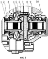
- front end and “rear end” herein are defined when the device is in the position shown in FIG. 2 , the right end is the “front end” and the left end is the “rear end”.
- the transmission in the present disclosure comprises an side gear 5, a pinion gear 6, a pinion shaft 7, a differential cover 4, a differential housing 9, a reducer cover 1, a reducer housing 10, a bearing 3, an side gear end cap 8, a differential oil seal 2, and other parts.
- the differential cover 4 is fixedly connected with the differential housing 9, an end of the differential cover 4 opposite from the differential housing 9 is provided with a bearing mounting seat, and the inside of the chamber formed by them is provided with a pair of side gears 5, a pair of pinion gears 6 and a pinion shaft 7. Both ends of the pinion shaft 7 are fixed on the differential housing 9.
- the pinion gears 6 are sleeved on both ends of the pinion shaft 7.
- the side gears 5 are meshed with the pinion gears 6.
- the inventiveness of the present invention lies in that an side gear end cap 8 and a differential oil seal 2 are further provided, wherein the side gear end cap 8 is assembled in the inner hole of the side gear 5 to seal the inner cavity of the differential and isolate the lubricating oil from the half shaft.
- the reducer housing 1 is equipped with a differential oil seal 2. A lip of the oil seal cooperates with the outer circumference of the side gear 5 to play a sealing role.
- the differential housing and the reducer housing are connected through the bearing 3 to form a dry differential.
- the half shaft is assembled in the inner hole of the side gear through a spline.
- connection way may not be specifically limited.
- the static sealing of the side gear end cap results in a simple sealing structure and high reliability; the differential oil seal is sealed with the outer circumference of the side gear, which, compared with the traditional structure in which the outer circumference of the half shaft is sealed, reduces the eccentricity and axial movement, and reduces the wear of the oil seal.
- the electric drive assembly having the above differential in the present disclosure works as follows.
- the motor drives the driving gear in the reducer to rotate
- the driving gear drives the driven gear to rotate
- the driven gear drives the differential assembly to revolve in the main reducer housing through the rotation of the differential housing.
- the pinion gears 6 mesh with the side gears 5 on both sides and revolve in the reducer housing together with the differential assembly, and the two half shafts transmit force and torque to the wheels through universal joints and other mechanisms to drive the wheels to rotate.
- the pinion gears 6 When the vehicle turns, the pinion gears 6 rotate.
- the pinion gears 6 transmit the revolution speed and the rotation speed itself to the outer wheel through the side gears 5, the half shaft and the universal joint, so that the rotation speed of the outer wheel is greater than that of the inner wheel, thereby realizing the smooth turning of the vehicle.
Landscapes
- Engineering & Computer Science (AREA)
- General Engineering & Computer Science (AREA)
- Mechanical Engineering (AREA)
- Chemical & Material Sciences (AREA)
- Combustion & Propulsion (AREA)
- Transportation (AREA)
- General Details Of Gearings (AREA)
- Retarders (AREA)
- Gasket Seals (AREA)
Applications Claiming Priority (2)
| Application Number | Priority Date | Filing Date | Title |
|---|---|---|---|
| CN201910827663.3A CN110594394A (zh) | 2019-09-03 | 2019-09-03 | 一种干式差速器的电驱动总成和新能源汽车 |
| PCT/CN2019/107800 WO2021042426A1 (zh) | 2019-09-03 | 2019-09-25 | 一种干式差速器的电驱动总成和新能源汽车 |
Publications (2)
| Publication Number | Publication Date |
|---|---|
| EP4006385A1 true EP4006385A1 (de) | 2022-06-01 |
| EP4006385A4 EP4006385A4 (de) | 2022-09-21 |
Family
ID=68857088
Family Applications (1)
| Application Number | Title | Priority Date | Filing Date |
|---|---|---|---|
| EP19943958.9A Withdrawn EP4006385A4 (de) | 2019-09-03 | 2019-09-25 | Elektrische antriebsanordnung eines trockendifferenzials und mit neuer energie gespeistes fahrzeug |
Country Status (5)
| Country | Link |
|---|---|
| US (1) | US20220268348A1 (de) |
| EP (1) | EP4006385A4 (de) |
| JP (1) | JP2022537594A (de) |
| CN (1) | CN110594394A (de) |
| WO (1) | WO2021042426A1 (de) |
Families Citing this family (1)
| Publication number | Priority date | Publication date | Assignee | Title |
|---|---|---|---|---|
| CN112378657B (zh) * | 2020-11-25 | 2022-03-01 | 山东蓬翔汽车有限公司 | 一种汽车驱动桥差速器总成润滑模拟综合实验台 |
Family Cites Families (40)
| Publication number | Priority date | Publication date | Assignee | Title |
|---|---|---|---|---|
| FR2211084A5 (de) * | 1972-12-19 | 1974-07-12 | Citroen Sa | |
| JPH08247155A (ja) * | 1995-03-10 | 1996-09-24 | Nissan Diesel Motor Co Ltd | 終減速機のシール構造 |
| JPH10213209A (ja) * | 1997-01-30 | 1998-08-11 | Aisin Aw Co Ltd | 自動変速機 |
| JP3622878B2 (ja) * | 1997-04-17 | 2005-02-23 | アイシン・エィ・ダブリュ株式会社 | 電気自動車用駆動装置 |
| JP2000297856A (ja) * | 1999-04-14 | 2000-10-24 | Tochigi Fuji Ind Co Ltd | ディファレンシャル装置 |
| JP2000297858A (ja) * | 1999-04-14 | 2000-10-24 | Tochigi Fuji Ind Co Ltd | ディファレンシャル装置 |
| US6413183B1 (en) * | 1999-04-14 | 2002-07-02 | Tochigi Fuji Sangyo Kabushiki Kaisha | Power transmission apparatus |
| JP2000297861A (ja) * | 1999-04-14 | 2000-10-24 | Tochigi Fuji Ind Co Ltd | ディファレンシャル装置 |
| JP3751488B2 (ja) * | 1999-11-17 | 2006-03-01 | 株式会社ユニバンス | Ff車両用変速機の差動装置 |
| US6270440B1 (en) * | 2000-02-07 | 2001-08-07 | Daimlerchrysler Corporation | Differential side gear with integral shaft |
| JP2001289306A (ja) * | 2000-04-04 | 2001-10-19 | Tochigi Fuji Ind Co Ltd | デファレンシャル装置 |
| JP4275337B2 (ja) * | 2001-11-29 | 2009-06-10 | ジヤトコ株式会社 | 変速機 |
| JP2005282801A (ja) * | 2004-03-30 | 2005-10-13 | Jatco Ltd | デファレンシャルギア |
| JP4431104B2 (ja) * | 2005-11-24 | 2010-03-10 | ジヤトコ株式会社 | 自動変速機におけるシールプラグの抜け止め構造 |
| JP4532428B2 (ja) * | 2006-03-29 | 2010-08-25 | ジヤトコ株式会社 | 自動変速機におけるシールプラグの抜け止め構造 |
| CN101830169A (zh) * | 2009-03-13 | 2010-09-15 | 德州齿轮有限公司 | 一种二级减速装置 |
| JP5208996B2 (ja) * | 2010-05-24 | 2013-06-12 | ジヤトコ株式会社 | 回転体支持構造 |
| JP5404727B2 (ja) * | 2011-09-28 | 2014-02-05 | ジヤトコ株式会社 | 差動装置によるシール構造 |
| CN202833915U (zh) * | 2012-09-04 | 2013-03-27 | 嘉兴敏凯汽车零部件有限公司 | 一种电动车减速器总成结构 |
| JP2014098401A (ja) * | 2012-11-13 | 2014-05-29 | Gkn Driveline Japan Ltd | 減速駆動装置 |
| CN203078306U (zh) * | 2013-02-08 | 2013-07-24 | 重庆动霸机械制造有限公司 | 电动车的后桥驱动减速装置 |
| JP2014173685A (ja) * | 2013-03-11 | 2014-09-22 | Jatco Ltd | シール構造、ディファレンシャル機構のシール構造およびシール構造の製造方法 |
| CN203594767U (zh) * | 2013-12-03 | 2014-05-14 | 陕西汉德车桥有限公司 | 汽车驱动桥主减速器总成 |
| JP6238353B2 (ja) * | 2014-02-03 | 2017-11-29 | 武蔵精密工業株式会社 | 差動装置及びその組立方法 |
| JP2015145703A (ja) * | 2014-02-03 | 2015-08-13 | 武蔵精密工業株式会社 | 差動装置 |
| JP2015148313A (ja) * | 2014-02-07 | 2015-08-20 | 武蔵精密工業株式会社 | 差動装置 |
| JP2015158256A (ja) * | 2014-02-25 | 2015-09-03 | 武蔵精密工業株式会社 | 差動装置 |
| CN204140814U (zh) * | 2014-10-07 | 2015-02-04 | 江山惠企科技服务有限公司 | 内密封式汽车差速器 |
| JP6460751B2 (ja) * | 2014-11-25 | 2019-01-30 | ナブテスコ株式会社 | シール装置および歯車伝動装置 |
| CN204459015U (zh) * | 2015-01-30 | 2015-07-08 | 陕西东铭车辆系统股份有限公司 | 一种带电磁双向离合器的两挡位变速电动车后桥减速器总成 |
| JP2016194330A (ja) * | 2015-03-31 | 2016-11-17 | アイシン・エィ・ダブリュ株式会社 | デファレンシャルギヤ |
| JP2017072202A (ja) * | 2015-10-07 | 2017-04-13 | 武蔵精密工業株式会社 | 差動装置 |
| CN105757210A (zh) * | 2016-04-23 | 2016-07-13 | 中国第汽车股份有限公司 | 一种两档电动汽车的集成式驱动装置 |
| JP6224800B2 (ja) * | 2016-10-05 | 2017-11-01 | 武蔵精密工業株式会社 | 差動装置 |
| JP2018066463A (ja) * | 2016-10-21 | 2018-04-26 | 武蔵精密工業株式会社 | 差動装置及びその組立方法 |
| CN106402324B (zh) * | 2016-12-07 | 2019-05-17 | 天津天海同步集团有限公司 | 电磁离合式电动汽车变速器 |
| CN207278824U (zh) * | 2017-09-14 | 2018-04-27 | 浙江中柴机器有限公司 | 一种半轴密封结构 |
| CN207945261U (zh) * | 2018-02-02 | 2018-10-09 | 江西乾元机械制造有限公司 | 一体式汽车差速器结构 |
| JP7013011B2 (ja) * | 2018-02-16 | 2022-01-31 | 株式会社イケヤフォ-ミュラ | デファレンシャル装置 |
| CN211145302U (zh) * | 2019-09-03 | 2020-07-31 | 精进电动科技股份有限公司 | 一种干式差速器的电驱动总成和新能源汽车 |
-
2019
- 2019-09-03 CN CN201910827663.3A patent/CN110594394A/zh active Pending
- 2019-09-25 JP JP2022514267A patent/JP2022537594A/ja active Pending
- 2019-09-25 EP EP19943958.9A patent/EP4006385A4/de not_active Withdrawn
- 2019-09-25 US US17/635,512 patent/US20220268348A1/en not_active Abandoned
- 2019-09-25 WO PCT/CN2019/107800 patent/WO2021042426A1/zh not_active Ceased
Also Published As
| Publication number | Publication date |
|---|---|
| WO2021042426A1 (zh) | 2021-03-11 |
| US20220268348A1 (en) | 2022-08-25 |
| JP2022537594A (ja) | 2022-08-26 |
| EP4006385A4 (de) | 2022-09-21 |
| CN110594394A (zh) | 2019-12-20 |
Similar Documents
| Publication | Publication Date | Title |
|---|---|---|
| CN111152837B (zh) | 一种双轮转向驱动轮 | |
| CN104640731B (zh) | 电动机驱动单元 | |
| CN103994187B (zh) | 电驱动两挡双级轮边减速器 | |
| CN203906681U (zh) | 电驱动两档双级轮边减速器 | |
| EP4006385A1 (de) | Elektrische antriebsanordnung eines trockendifferenzials und mit neuer energie gespeistes fahrzeug | |
| CN112161027A (zh) | 一种工程车轮边行走行星减速装置 | |
| CN211145302U (zh) | 一种干式差速器的电驱动总成和新能源汽车 | |
| CN213575373U (zh) | 一种工程车轮边行走行星减速装置 | |
| CN106828086B (zh) | 一种六轮驱动矿用框架式搬运车 | |
| CN210553944U (zh) | 一种限位机构、转向节减震结构及拖拉机前驱动桥 | |
| CN210760074U (zh) | 转向驱动前桥总成和车辆 | |
| CN111267980A (zh) | 一种高载荷防爆驱动装置 | |
| CN206439405U (zh) | 一种取力器总成输入轴端部密封结构 | |
| CN203078225U (zh) | 挖掘机转向驱动前桥 | |
| CN212447099U (zh) | 电动车的驱动轮的驱动结构 | |
| CN211778832U (zh) | 一种新型自密封差速器 | |
| CN211493538U (zh) | 一种集成电机的电动车后驱动桥总成 | |
| CN201723686U (zh) | 带整球形内腔的差速器壳体 | |
| CN219888639U (zh) | 一种纵置动力输入驱动箱总成及电动车 | |
| CN106989112A (zh) | 带金属防护的分段安装等速万向节驱动轴 | |
| JPH0449376Y2 (de) | ||
| CN112928859A (zh) | 一种差速功能转子以及驱动电机 | |
| CN223370515U (zh) | 一种端面设有防漏油结构的驱动桥桥壳 | |
| CN211519145U (zh) | 一种新型支撑形式的驱动桥末端结构 | |
| CN219623180U (zh) | 差速器总成和车辆 |
Legal Events
| Date | Code | Title | Description |
|---|---|---|---|
| STAA | Information on the status of an ep patent application or granted ep patent |
Free format text: STATUS: THE INTERNATIONAL PUBLICATION HAS BEEN MADE |
|
| PUAI | Public reference made under article 153(3) epc to a published international application that has entered the european phase |
Free format text: ORIGINAL CODE: 0009012 |
|
| STAA | Information on the status of an ep patent application or granted ep patent |
Free format text: STATUS: REQUEST FOR EXAMINATION WAS MADE |
|
| 17P | Request for examination filed |
Effective date: 20220223 |
|
| AK | Designated contracting states |
Kind code of ref document: A1 Designated state(s): AL AT BE BG CH CY CZ DE DK EE ES FI FR GB GR HR HU IE IS IT LI LT LU LV MC MK MT NL NO PL PT RO RS SE SI SK SM TR |
|
| TPAC | Observations filed by third parties |
Free format text: ORIGINAL CODE: EPIDOSNTIPA |
|
| STAA | Information on the status of an ep patent application or granted ep patent |
Free format text: STATUS: EXAMINATION IS IN PROGRESS |
|
| A4 | Supplementary search report drawn up and despatched |
Effective date: 20220824 |
|
| RIC1 | Information provided on ipc code assigned before grant |
Ipc: F16H 48/38 20120101ALI20220818BHEP Ipc: F16H 57/029 20120101AFI20220818BHEP |
|
| 17Q | First examination report despatched |
Effective date: 20220905 |
|
| STAA | Information on the status of an ep patent application or granted ep patent |
Free format text: STATUS: THE APPLICATION HAS BEEN WITHDRAWN |
|
| DAV | Request for validation of the european patent (deleted) | ||
| DAX | Request for extension of the european patent (deleted) | ||
| 18W | Application withdrawn |
Effective date: 20221118 |