EP4006400B1 - Druckausgleichsvorrichtung - Google Patents
Druckausgleichsvorrichtung Download PDFInfo
- Publication number
- EP4006400B1 EP4006400B1 EP21207222.7A EP21207222A EP4006400B1 EP 4006400 B1 EP4006400 B1 EP 4006400B1 EP 21207222 A EP21207222 A EP 21207222A EP 4006400 B1 EP4006400 B1 EP 4006400B1
- Authority
- EP
- European Patent Office
- Prior art keywords
- piston
- fluid
- pressure
- pressure compensation
- housing
- Prior art date
- Legal status (The legal status is an assumption and is not a legal conclusion. Google has not performed a legal analysis and makes no representation as to the accuracy of the status listed.)
- Active
Links
Images



Classifications
-
- F—MECHANICAL ENGINEERING; LIGHTING; HEATING; WEAPONS; BLASTING
- F16—ENGINEERING ELEMENTS AND UNITS; GENERAL MEASURES FOR PRODUCING AND MAINTAINING EFFECTIVE FUNCTIONING OF MACHINES OR INSTALLATIONS; THERMAL INSULATION IN GENERAL
- F16L—PIPES; JOINTS OR FITTINGS FOR PIPES; SUPPORTS FOR PIPES, CABLES OR PROTECTIVE TUBING; MEANS FOR THERMAL INSULATION IN GENERAL
- F16L55/00—Devices or appurtenances for use in, or in connection with, pipes or pipe systems
- F16L55/04—Devices damping pulsations or vibrations in fluids
- F16L55/045—Devices damping pulsations or vibrations in fluids specially adapted to prevent or minimise the effects of water hammer
- F16L55/05—Buffers therefor
- F16L55/052—Pneumatic reservoirs
- F16L55/053—Pneumatic reservoirs the gas in the reservoir being separated from the fluid in the pipe
-
- A—HUMAN NECESSITIES
- A47—FURNITURE; DOMESTIC ARTICLES OR APPLIANCES; COFFEE MILLS; SPICE MILLS; SUCTION CLEANERS IN GENERAL
- A47J—KITCHEN EQUIPMENT; COFFEE MILLS; SPICE MILLS; APPARATUS FOR MAKING BEVERAGES
- A47J31/00—Apparatus for making beverages
- A47J31/44—Parts or details or accessories of beverage-making apparatus
- A47J31/46—Dispensing spouts, pumps, drain valves or like liquid transporting devices
Definitions
- the invention relates to a pressure compensation device for compensating pressure fluctuations of a fluid in a fluid line, having a housing which has a connection for connecting the fluid line, and a pressure compensation element which is arranged to be movable relative to the housing in order to compensate for the pressure fluctuations.
- the invention further relates to a method for compensating pressure fluctuations of a fluid in a fluid line and to a device, in particular a drinks machine, with a pressure compensation device.
- Pressure compensation devices are used in very different areas of technology and are primarily used when a fluid within fluid lines expands or contracts due to temperature changes. The expansion or contraction of the fluid in the fluid lines leads to pressure fluctuations within the fluid lines, which are partially or completely compensated for by the pressure compensation device so that the line system or the devices connected to it are not impaired or damaged by the pressure fluctuations.
- Known pressure compensation devices have a housing with a connection to which the fluid line, such as a pipe or a hose, is connected. The fluid is fed into the pressure compensation device via the connection.
- a pressure compensation element enables the pressure fluctuations of the fluid in the fluid line to be compensated for by being arranged to be movable relative to the housing and in this way forming a pressure compensation chamber of variable size.
- expansion vessels are often used as pressure compensation devices, in which a flexible membrane arranged within a housing is movably accommodated relative to the housing for the purpose of pressure compensation.
- the fluid lies on one side of the flexible membrane, so that when the pressure of the fluid fluctuates, it is deformed and moved relative to the housing, which results in a variable pressure compensation space and the pressure fluctuation is compensated for accordingly. In this way, the pressure within a heating system is kept essentially constant.
- the membrane on the side opposite the fluid is often additionally exposed to a protective gas, in particular nitrogen.
- the protective gas forms a pressure accumulator that counteracts the pressure of the heating system and also serves to delay embrittlement of the membrane compared to exposure to atmospheric oxygen and thus increase the operating time of the device. Due to the necessary application of nitrogen to the membrane, such pressure compensation devices require a high level of manufacturing effort due to their design, since, for example, the housing must be designed to be gas-tight and with a filling connection, such as a valve.
- the DE 10 2015 203 231 A1 shows a vibration absorber with a volume recording that is not linear.
- the GB 1 456 274 A shows a braking device for vehicle brakes.
- the US 6,997,523 B1 shows a fluid damping system, also for vehicle brakes.
- the AU 2014364880 B2 shows a pressure reducing device with a piston arranged to be movable against a pressure chamber. From the US 5,385,172 a pressure compensation device for fluidic applications with a movable piston is known.
- the EP 2 067 423 A shows a multi-function valve for beverage machines.
- the present invention is therefore based on the object of creating a pressure compensation device which is characterized by a simple structure.
- the design of the pressure compensation element as a movable piston results in a simple structure of the pressure compensation device.
- the pressure compensation devices can be manufactured inexpensively and used for a variety of applications. Complex assembly and manufacturing measures, such as sealing a membrane between two housing halves or applying protective gas on one side, as is required in solutions known from the prior art, are eliminated.
- the piston moves relative to the housing, creating a pressure compensation chamber of variable size, through which the pressure fluctuations are compensated.
- the piston can be moved back and forth between two stops.
- the stops can be used to limit the movement of the piston in that the stops determine positions of the piston in which the piston hits one of the stops. It is possible to use the stops to define the pressure compensation space, in particular the maximum pressure compensation space.
- One of the stops can determine the movement of the piston at a high pressure of the fluid in the fluid line.
- the other stop can determine the movement of the piston at a low pressure of the fluid in the fluid line.
- At least one stop can be designed as a component of the housing, in particular as a component of the connection.
- At least a stop, in particular both stops can be designed as a stop surface.
- the fluid side of the piston can correspond to an end face of the piston.
- the dry side may correspond to the opposite end face of the piston. It is possible for the dry side of the piston in particular to be subjected to a force, such as the spring force of a spring, in addition to the ambient pressure.
- the piston is guided in a piston receptacle.
- the piston holder allows the movement of the piston to be controlled in a structurally simple manner.
- the piston receptacle can be designed as part of the housing or alternatively as a separate component.
- the design as part of the housing can reduce the number of individual parts of the pressure compensation device.
- the piston receptacle can be designed as a lid or cap, with the piston being able to be accommodated within the piston receptacle.
- the piston receptacle can be cup-shaped.
- the piston can be guided coaxially to the main axis of the piston receptacle.
- the piston can be guided linearly within the piston holder.
- the piston is sealed from the piston receptacle using sealing means.
- the sealants can be designed differently.
- one of the sealing means is designed as a circumferential seal and the other sealing means is designed as a surface seal on the end face.
- the circulating seal can be arranged on the lateral surface of the piston.
- the surface seal can be arranged on an end face, in particular on the dry side of the piston. It is possible that the surface seal improves the sealing effect, particularly at high pressures of the fluid in the fluid line.
- the sealants can be designed as an O-ring.
- the piston receptacle advantageously has a pressure compensation opening on the dry side of the piston.
- a constant pressure which corresponds in particular to the ambient pressure, can be achieved on the dry side of the piston.
- the pressure equalization opening it is possible for the pressure equalization opening to be designed as a hole. In the case of a piston receptacle designed as a cup-shaped lid or cap, it is possible for the pressure equalization opening to be arranged at the bottom of the piston receptacle.
- the piston receptacle and the piston form an assembly unit that can be permanently mounted on the housing.
- the non-detachable connection ensures fluid-tight assembly on the housing.
- the assembly unit can be mounted on the housing in just one assembly step, whereby the assembly effort of the pressure compensation device can be reduced.
- the piston can be inserted into the piston holder.
- the piston receptacle it is possible for the piston receptacle to have at least one fastening means for permanent fastening to the housing, which is used to mount the Assembly unit is used.
- the fastening means can be designed as a snap or latching hook or in the manner of an adhesive connection.
- the mounting unit is possible for the mounting unit to be pluggable or clip-mounted on the housing, in particular on a connection.
- the mounting unit can be detachably mounted on the housing.
- the assembly unit can be detachably mounted on the housing, in particular on a connection, in a pluggable, clipped or screwed manner.
- the fastening means can be designed as a detachable snap or latching hook or in the manner of a thread.
- a further advantageous embodiment of the invention provides that the piston receptacle is sealed on the circumference from the housing via a seal.
- the seal can be designed as a circumferential seal, in particular as an O-ring. It is possible for the seal to be arranged on the circumference of the lateral surface of the piston receptacle.
- the assembly unit is mounted on a connection of the housing.
- the additional connection allows the assembly unit, i.e. the piston holder and the piston, to be mounted on the housing in an easy-to-assemble manner.
- a fluid line can be connected to the first connection of the pressure compensation device, the assembly unit can be mounted on the further connection, for example by clipping, plugging or screwing.
- the connection can be designed as a quick connector connection for quick assembly. Using the quick connector connection, the assembly unit can be mounted directly on the connection without any additional tools.
- connection of the assembly unit and the connection of the fluid line are designed to be identical in construction and the assembly unit can optionally be mounted on one of the connections. Due to the identical design of the connections, it is possible to adapt the pressure compensation device particularly flexibly to the respective application by optionally mounting the assembly unit on one of the connections. For example, it is conceivable that the assembly unit is connected to the first connection and the fluid line to the second connection. Alternatively, it is also possible to arrange the fluid line on the first connection and the assembly unit on the second connection. Due to the identical design of the connections, for example as quick connector connections, the structure of the pressure compensation device is simplified. It is possible for both connections to be designed as cup-shaped connections.
- the quick connector can have a clamping element and a release actuation.
- the clamping element can be designed as a clamping ring, which, in the case of a fluid line received in the connection, such as a pipe or a hose, fastens the fluid line in a clamping manner in the connection.
- the release actuation can be actuated by a user, thereby releasing the clamping attachment of the clamping element and dismantling the fluid line from the connection.
- the release actuation can be designed as a pressure actuation.
- connection can be designed as a, in particular cup-shaped, quick connector connection. It is possible for the quick connector to be removable at the fluid line connection. This allows the connection of the fluid line to be optionally connected the assembly unit can be converted. In connection with the design of the quick connector, it is possible in particular for the connection of the fluid line to further have a sealant which can seal the fluid line from the connection.
- the connections each have at least two stop surfaces spaced apart in the axial direction, the position of the assembly unit being able to be determined via one stop surface and the position of the fluid line being able to be determined via the other stop surface.
- the stop surfaces can be formed by changing the cross section of the respective connection.
- the stop surface for determining the position of the fluid line can have a dual function. It is therefore possible for the stop surface to determine the position of the fluid line to simultaneously be designed as a stop of the piston to limit the movement of the piston.
- the housing is advantageously designed in one piece.
- the housing can be designed as an I-, L-, X-, Y- or T-shaped housing. Other shapes are also possible. It is possible for the I- or L-shaped housing to have two connections for connecting a fluid line and the mounting unit. It is also possible for the T-shaped housing to have three connections to which fluid lines and the assembly unit can optionally be connected.
- the housing is designed as a flow-through housing with a third connection for connecting a second fluid line.
- This configuration allows the pressure compensation device to be connected to several fluid lines in a particularly simple manner. So it is possible for the fluid to flow from one fluid line can flow out through the housing to the other fluid line.
- the third connection can be designed to be identical to one or both connections.
- the mounting unit or the piston receptacle can be mounted on the third connection of the housing. It is possible for the pressure compensation device with the housing designed as a flow housing to serve as a fluid line connector.
- the housing As an alternative to the design as a flow housing, it is also possible to design the housing as a storage space housing in which the fluid accumulates from the connection of the fluid line to the assembly unit or the piston receptacle.
- a further advantageous embodiment of the invention provides an indicator arranged on the piston to display the pressure in the fluid line.
- the indicator shows the pressure in the fluid line by changing its position depending on the pressure of the fluid in the fluid line.
- the indicator is arranged on an end face of the piston, in particular on the dry side of the piston.
- the piston can be moved depending on the pressure in the fluid line, so that the indicator on the end face can display different pressures in the fluid line.
- the indicator is designed as an indicator pin, in particular arranged on the end face of the piston.
- the indicator pin can be moved with the piston through the pressure equalization opening.
- the pressure equalization opening fulfills a double function.
- the indicator can be designed in one piece as part of the piston.
- the indicator can have colored components, for example a colored surface. It is also conceivable that the indicator serves as a trigger element of a mechanical and/or electrical switch, which, for example, enables the pressure within the fluid line to be monitored.
- the piston is biased towards its fluid side via a spring arranged on its dry side.
- a spring arranged on its dry side.
- the minimum pressure required in the fluid line, from which the piston is moved relative to the housing, can be determined in a structurally simple manner.
- the spring can be designed as a compression spring.
- the spring can form part of the assembly unit.
- the spring can be accommodated in the, in particular cup-shaped, piston receptacle. It is possible that the spring biases the piston relative to the piston seat. It is possible for the spring to be supported on one side relative to one of the stops for determining the movement of the piston.
- the indicator arranged on the end face of the piston, in particular the indicator pin to be movable inside the spring along the main axis of the spring.
- the piston has a spring receptacle for receiving the compressed spring.
- the spring holder can at least partially or completely accommodate the spring in its compressed state. This maintains the functionality of the stop for determining the movement of the piston.
- the spring receptacle can be designed to correspond to the spring.
- the spring holder can be arranged on an end face of the piston, in particular on its dry side.
- the spring holder can be designed as a circumferential groove on one end face of the piston.
- the piston has a recess on its fluid side.
- the recess can be arranged on an end face of the piston.
- the recess can be designed as a hole, in particular a blind hole.
- the main axis of the recess can run coaxially with the main axis of the piston.
- a device in particular a drinks machine, with a boiler for heating a fluid, a main valve for removing the Fluids via a fluid line and a pressure compensation device for compensating for pressure fluctuations of the fluid in the fluid line as a result of temperature fluctuations of the fluid suggested that the pressure compensation device has one or more of the above features.
- the main valve is designed as a direct-switching valve.
- the valve can be designed as a 3/2-way valve. This makes it possible for the valve to relieve the fluid line outlet in order to completely empty the fluid outlet, for example when a beverage is removed.
- the main valve As an alternative to the design as a direct-switching valve, it is also possible for the main valve to be designed as a servo valve that can be actuated by its own medium, in particular as a diaphragm valve. It is possible that the servo valve can be actuated via a pilot valve. A design as a directly switchable membrane valve is also possible.
- the pressure compensation element designed as a piston is moved to form a variable pressure compensation space.
- the pressure compensation device can have one or more of the features mentioned above. This results in the advantages discussed in connection with the pressure compensation device.
- the Fig. 1 and 2 each show a schematic view of a drinks machine 30, which can be, for example, a fully automatic coffee machine.
- the drinks machine 30 points according to Fig. 1 a boiler 31 designed as a pressure boiler, which in the exemplary embodiment heats water as fluid F, which is used to prepare hot drinks such as coffee, tea or the like.
- the boiler 31 is connected via a fluid line 100 to a main valve 32, via which the water heated in the boiler 31 can be removed from the drinks machine 30, for example into a cup 33.
- the main valve 32 is designed as a direct-switching valve and opens and closes by a sealing element 34 made of an elastic material releasing or closing a valve seat 35.
- the main valve 32 is designed as a 3/2-way valve, which allows the fluid line outlet 101 to be completely emptied when the beverage is removed.
- the main valve 32 has a channel, not shown, which ventilates the fluid line outlet 101 when the main valve 32 is closed, whereby it can be completely emptied.
- the water in the boiler 31 is first heated, led via the fluid line 100 to the main valve 32 and removed there via the main valve 32.
- the main valve 32 is then closed, for example as a sealing ring or surface seal designed sealing element 34 closes the valve seat 35.
- the fluid F in the fluid line 100 is thereby trapped between the boiler 31 and the closed main valve 32 and gradually begins to cool. Due to the associated change in volume of the water, the pressure conditions change and a negative pressure is created in the fluid line 100. Due to this pressure fluctuation, the main valve 32 and in particular its sealing element 34 are increasingly pressed onto the valve seat 35. As a result, damage to the sealing element 34 can occur over time and the service life of the drinks machine 30 can be impaired or comparatively narrow maintenance intervals may be required.
- the drinks machine is 30 according to Fig. 2 in the area between the boiler 31 and the main valve 32 is equipped with a pressure compensation device 1, via which such pressure fluctuations are compensated for.
- the structure and operation of the pressure compensation device 1 will be discussed in more detail below, with it being pointed out that not only negative pressures but also excess pressures can be compensated for via the pressure compensation device 1.
- the Fig. 3 shows the pressure compensation device 1 according to Fig. 2 in an enlarged, partially sectioned view.
- the pressure compensation device 1 has a housing 2 designed in one piece.
- the housing 2 is designed as a flow housing through which the fluid F flows.
- the housing 2 has three identical, pot-shaped connections 3.
- the connections 3 are arranged relative to one another in such a way that the housing 2 has a T-shaped shape.
- a fluid line 100 is connected to two axially oppositely arranged connections 3, so that the fluid F flows axially through the housing 2.
- These connections 3 are quick connector connections designed and each have a quick connector 24 for connecting the fluid lines 100.
- the quick connector 24 is formed from a clamping element 26 designed as a clamping ring and a pressure-operated release actuation 25.
- the release actuation 25 is designed as a release ring, see also 5 and 6 .
- the fluid line 100 for example a pipe or a hose, can be connected to the respective connection 3 without tools and removed again via the quick connectors 24 of the connections 3.
- a seal 27 for example an O-ring, is arranged within the connections 3 as part of the quick connector 24.
- connection 3 does not have a quick connector 24, but could also be equipped with one since the three connections 3 are constructed identically.
- the piston receptacle 8 is designed in one piece as a socket with a cup-shaped cross section. To attach the piston receptacle 8 to the connection 3, the piston receptacle 8 has fastening means 10 arranged on the circumference.
- the fasteners 10 are according to Fig. 3 designed as a locking hook.
- the piston receptacle 8 is fastened in the connection 3 in a latching manner.
- other types of fastening are also conceivable, for example by screwing, clamping, gluing or similar.
- the piston receptacle 8 is sealed from the connection 3 via a seal 13.
- the seal 13 is designed as an O-ring and is arranged on the circumference on the outside of the piston receptacle 8.
- the seal 13 acts as a radial seal.
- the piston receptacle 8 has a circumferential groove 17 to accommodate the seal 13.
- a piston 4 is movably mounted within the cup-shaped piston receptacle 8.
- the piston 4 and the piston receptacle 8 together form an assembly unit 19.
- the assembly unit 19 enables particularly simple assembly in that it can be mounted on a connection 3 in a single assembly step. For example, it is conceivable that the assembly unit 19 is inserted into the connection 3 and then locked via the fastening means 10 of the piston receptacle 8.
- the assembly unit 19 could alternatively also be arranged on one of the other two connections 3, for example in order to adapt the pressure compensation device 1 to an application.
- the assembly unit 19 is permanently mounted on the housing 2. This prevents the assembly unit 19 from being detached from the housing 2 in the event of pressure fluctuations in the fluid F, in particular in the event of excess pressure, in the fluid lines 100.
- the non-detachable assembly prevents leaks due to pressure fluctuations.
- the connections 3 each have two stop surfaces 20, 21.
- the stop surfaces 20, 21 are designed as annular stop surfaces and are arranged one behind the other in the axial direction of the connections 3.
- the assembly unit 19 can be easily mounted via the one stop surface 20. In the event that a fluid line 100 is connected to a connection 3, the seal 27 rests on the stop surface 20 of the connection 3.
- the other stop surface 21 enables a defined insertion of the fluid line 100 when it is mounted on the connection 3.
- the fluid line 100 is along the main axis of the connection 3 up to the Stop surface 21 pushed in.
- the stop surface 21 limits the connection 3 in the axial direction. In the event that a mounting unit 19 is connected to the connection 3, the stop surface 21 allows the movement of the piston 4 to be limited.
- the diameter of the piston 4 is designed to be essentially the same as the diameter of the stop surface 21.
- connections 3 are divided into two areas, a mounting area 28 and a receiving area 29 oriented towards the center of the housing.
- the areas 28, 29 are delimited by the stop surfaces 20, 21.
- the mounting area 28 enables the arrangement of the quick connector 24 in the connection 3.
- the mounting area 28 is designed such that a seal 27, a clamping element 26 and a release actuation 25 can be fastened one behind the other in the connection 3 in the axial direction.
- the assembly area 28 is designed essentially cylindrical and has a gradation towards the receiving area 29, which simplifies the assembly of the quick connector 24. The gradation corresponds to Fig. 3, 4 the stop surface 20.
- the mounting area 28 enables the mounting of the mounting unit 19.
- the mounting unit 19 is inserted in the axial direction into the mounting area 28 until it rests on the step comes.
- the receiving area 29 borders the mounting area 28 and allows the fluid line 100 to be received.
- the receiving area 29 is cylindrical and has a smaller diameter than the mounting area 28.
- the receiving area 29 also has a gradation which corresponds to the stop surface 21.
- the piston 4 can be moved into the receiving area 29.
- the piston 4 is therefore designed in such a way that the piston 4 can be moved into the receiving area 29.
- the diameter of the piston 4 is essentially the same as the diameter of the receiving area 29.
- the maximum pressure compensation space R can be determined via the size of the receiving area 29.
- the essentially cylindrical piston 4 is sealed from the piston receptacle 8 via several sealants, although it would also be possible here to provide a single sealant.
- a first seal 11 designed as an O-ring is provided on the circumference on the outer surface of the piston 8. To arrange the seal 11 on the outer surface of the piston 4, it has a circumferential groove 5 in which the seal 11 is arranged.
- a seal 12 designed as an O-ring is arranged on the end face of the piston 4.
- the sealing means 11, 12 designed as redundant seals can ensure a sufficient sealing effect even in the event of high pressure fluctuations or pressure peaks within the fluid lines 100.
- the sealing means 11, 12 and the seal 13 can be components of the assembly unit 19. In addition, the seal 12 can continue to guarantee the sealing effect in the event of wear of the seal 11.
- the piston 4 mounted in the piston receptacle 8 has a fluid side 22.
- the piston 4 has a dry side 23.
- the fluid side 22 of the piston 4 is the side that faces the fluid F.
- the piston 4 is in contact with the fluid F, which is why the fluid pressure is present on the fluid side 22.
- the dry side 23 opposite the fluid side 22 faces away from the fluid F and is dry.
- two seals 11, 12 are arranged on the piston 4, which seal the fluid side 22 and the dry side 23 from one another.
- a pressure compensation opening 9 serves to equalize the pressure inside the piston receptacle 8 on the dry side 23 of the piston 4 with the ambient pressure.
- the movement of the piston 4 mounted in the piston receptacle 8 is limited by stops 6, 7, see also Fig. 4 .
- the stop 6 is designed as part of the piston receptacle 8 and limits the movement of the piston 4 in one direction, as shown Fig. 3 up.
- the stop 7 is designed as part of the housing 3 and limits the movement of the piston 4 in the opposite direction as shown Fig. 3 downward.
- the stop 7 arranged on the housing 3 corresponds to the stop surface 21.
- the stops 6, 7 are designed as annular surfaces against which the piston 4 abuts flatly.
- the piston 4 also has an indicator 14 arranged on the dry side 23, the functionality of which will be discussed below in connection with 5 and 6 will be discussed in more detail.
- the indicator 14 is designed as a cylindrical indicator pin, although different configurations are also possible here, for example as a cone-shaped indicator pin, as a color indicator, as an acoustic indicator or other optical indicators.
- the piston 4 In the Fig. 3 the piston 4 is in a first position.
- the pressure of the fluid F in the fluid lines 100 is equal to or greater than the ambient pressure, which is why the piston 4 is moved into the first position. This is the case, for example, when operating the drinks machine 30, cf. Fig. 2 .
- a pressure compensation chamber R is formed below the piston 4. The pressure compensation chamber R is variable depending on the position of the piston 4. In the first position of the piston 4, the pressure compensation chamber R is at its maximum size.
- the pressure compensation device 1 can compensate for pressure fluctuations in the fluid F. Pressure fluctuations can occur, for example, when the fluid F cools and the volume of the fluid F within the fluid lines 100 reduces. This is the case, for example, when the drinks machine 30 is switched off if the fluid F is no longer tempered via the boiler 31, cf. also Fig. 2 . Due to the falling pressure, the piston 4 is moved from the first position in the piston holder 8 Fig. 3 sucked below. This reduces the pressure compensation space R and compensates for the change in volume of the fluid F. The movement of the piston 4 creates a pressure equilibrium between the pressures prevailing on the fluid side 22 and the dry side 23. It is possible for the piston 4 to assume a position between the first position in which the piston 4 abuts the stop 6 and the second position in which the piston 4 abuts the stop 7.
- the piston 4 is in the second position. From this second position, the pressure compensation device 1 can also compensate for pressure fluctuations in the fluid F. For example, it is conceivable that the fluid F is heated, which results in an increase in the volume of the fluid F within the fluid lines 100. As a result, the pressure within the fluid lines 100 increases and the piston 4 is used to compensate Fig. 4 moved above. As a result, the pressure equalization space R is enlarged accordingly. Here too, a pressure equilibrium is established across the piston 4.
- the size of the pressure compensation chamber R corresponds to the maximum volume change of the fluid F, which can be compensated for by the pressure compensation device 1.
- the piston 4 In its second position, the piston 4 emerges at least partially from the piston receptacle 8, whereby a larger pressure compensation chamber R can be realized.
- Fig. 5 and Fig. 6 the pressure compensation device 1 is shown in a perspective view from the outside.
- the piston 4 is in the first position according to Fig. 3 and in Fig. 6 in the second position accordingly Fig. 4 .
- the fluid lines 100 have not been shown in these figures.
- the indicator 14 designed as an indicator pin in an easily recognizable signal color, is arranged on the dry side 23 of the piston 4, cf. Fig. 3, 4 .
- the indicator 14 In the first position of the piston 4 according to Fig. 5 the indicator 14 is moved through the pressure equalization opening 9 of the piston receptacle 8. This means that a user can see from the indicator 14 that the piston 4 is in the first position.
- the pressure equalization opening 9 therefore has a dual function. On the one hand, as explained above, this balances the pressure on the dry side 23 of the piston 4 compared to the environment. On the other hand, this interacts with the indicator 14 and allows the position of the piston 4 to be read from outside the piston receptacle 8.
- the indicator 14 In the second position of the piston 4 according to Fig. 6 the indicator 14 is not moved through the pressure equalization opening 9 and is therefore not visible from the outside. It is possible for the indicator 14 to also indicate intermediate positions of the piston 4, for example by the indicator pin not being completely moved through the pressure compensation opening 9. In this context, it is possible for the indicator pin to have a scale which shows the position, in particular the intermediate position, of the piston 4.
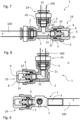
- Fig. 7 to 9 show further exemplary embodiments of pressure compensation devices 1 according to the invention. The following will focus primarily on the differences from the pressure compensation device discussed above Fig. 3 To be received.
- the pressure compensation device 1 shown is identical in construction to the pressure compensation device 1 Fig. 3 designed, wherein the mounting unit 19 is mounted on a connection 3 opposite the fluid line 100.
- the result is a flow housing that is angled at 90°.
- the assembly unit 19 can be optionally mounted on any connection 3. If, for example, the assembly unit 19 is to be mounted from the right-hand connection 3 in the illustration to the upper connection 3, then the quick connector 24 mounted on the upper connection 3 would first have to be removed, the assembly unit 19 would have to be dismantled from the right-hand connection 3 and then attached to it top connection 3 to be mounted. The quick connector 24 could then be mounted on the right-hand connection 3.
- the housing 2 is designed as a storage housing.
- the housings 2 therefore each only have two connections 3.
- the assembly unit 19 formed from piston 4 and piston receptacle 8 is arranged at one of the connections 3, the left-hand connection 3 in the illustrations.
- a fluid line 100 is arranged at the other connection 3.
- connection 3 of the fluid line 100 is according to the exemplary embodiment Fig. 8 , as explained above, designed as a quick connector connection with a quick connector 24. Furthermore, the housing 2 is L-shaped here.
- connection 3 of the fluid line 100 is designed as a plug-in connection onto which the fluid line 100, for example a hose, can be easily plugged.
- the housing 2 is designed here I-shaped.
- a pressure compensation device 1 which is essentially identical in construction to that in Fig. 7 pressure compensation device 1 shown, but has a spring-loaded piston 4.
- the pressure compensation device 1 has a spring 15 serving as a return spring.
- the spring 15 is part of the assembly unit 19.
- the spring 15 is arranged on the dry side 23 of the piston 4.
- the dry side 23 of the piston 4 is now subjected to the spring force of the spring 15 in addition to the ambient pressure of the environment U.
- the response of the piston 4 can be adjusted via the spring 15.
- Fig. 10 It can be seen that the spring 15 is received in its compressed state by a spring receptacle 18. This makes it possible for the piston 4 to continue to strike the stop 6. The first position of the piston 4 therefore does not change due to the arrangement of the spring 15.
- the spring receptacle 18 is designed as a circumferential groove which is arranged on the end face of the piston 4.
- the piston 4 If the operating pressure, such as 4 bar, is generated in the fluid lines 100, the piston 4 initially remains in the position shown Fig. 11 .
- the spring 15 must be selected according to the desired operating pressure. If there is now a sudden increase in pressure of the fluid F within the fluid line 100, i.e. an undesirable pressure peak, this can be caused by moving the piston 4 towards the first position Fig. 10 can be compensated for by enlarging the pressure compensation chamber R accordingly.
- the pressure compensation devices 1 described are characterized by a pressure compensation element designed as a movable piston 4 to form a variable pressure compensation chamber R, which results in a particularly simple structure of the pressure compensation devices 1.
Landscapes
- Engineering & Computer Science (AREA)
- General Engineering & Computer Science (AREA)
- Food Science & Technology (AREA)
- Mechanical Engineering (AREA)
- Measuring Fluid Pressure (AREA)
- Supply Devices, Intensifiers, Converters, And Telemotors (AREA)
- Control Of Fluid Pressure (AREA)
- Vehicle Body Suspensions (AREA)
- Measuring Pulse, Heart Rate, Blood Pressure Or Blood Flow (AREA)
- Fluid-Pressure Circuits (AREA)
Applications Claiming Priority (1)
| Application Number | Priority Date | Filing Date | Title |
|---|---|---|---|
| DE102020131306.3A DE102020131306A1 (de) | 2020-11-26 | 2020-11-26 | Druckausgleichsvorrichtung |
Publications (2)
| Publication Number | Publication Date |
|---|---|
| EP4006400A1 EP4006400A1 (de) | 2022-06-01 |
| EP4006400B1 true EP4006400B1 (de) | 2023-11-01 |
Family
ID=78592644
Family Applications (1)
| Application Number | Title | Priority Date | Filing Date |
|---|---|---|---|
| EP21207222.7A Active EP4006400B1 (de) | 2020-11-26 | 2021-11-09 | Druckausgleichsvorrichtung |
Country Status (4)
| Country | Link |
|---|---|
| EP (1) | EP4006400B1 (da) |
| DE (2) | DE102020131306A1 (da) |
| DK (1) | DK4006400T3 (da) |
| ES (1) | ES2967464T3 (da) |
Families Citing this family (3)
| Publication number | Priority date | Publication date | Assignee | Title |
|---|---|---|---|---|
| DE102023004784A1 (de) * | 2023-11-22 | 2025-05-22 | Mercedes-Benz Group AG | Betätigungsvorrichtung zum Betätigen eines Schaltelements eines Getriebes für einen Kraftfahrzeugantriebsstrang |
| DE102024206057A1 (de) * | 2024-06-28 | 2025-12-31 | Schaeffler Technologies AG & Co. KG | Vorrichtung zur Minderung des Drucks infolge des Einfrierens eines Fluidleitungsabschnitts |
| DE102024208141A1 (de) * | 2024-08-27 | 2025-08-14 | Schaeffler Technologies AG & Co. KG | Flüssigkeitsadapter, Flüssigkeitsleitungssystem und Fahrzeug |
Family Cites Families (9)
| Publication number | Priority date | Publication date | Assignee | Title |
|---|---|---|---|---|
| CA1021830A (en) | 1973-11-19 | 1977-11-29 | Robert G. Booth | Pressure equalizing and stabilization device for hydraulic brake systems |
| FR2655128B1 (fr) | 1989-11-29 | 1992-03-27 | Automotive Prod France | Dispositif de filtrage de vibrations, notamment pour commande hydraulique d'embrayage de vehicules automobiles. |
| US5385172A (en) * | 1994-01-03 | 1995-01-31 | Precision Plumbing Products, Inc. | Ping-free water hammer arrester |
| EP0780079B1 (fr) * | 1995-12-21 | 2000-02-02 | Reneka International | Unité individuelle de préparation et de distribution du café pour machine à café du type dit "expresso" |
| FR2762662B1 (fr) | 1997-04-23 | 1999-05-28 | Valeo | Amortisseur de vibrations d'une pedale de debrayage pour vehicule automobile |
| US6997523B1 (en) | 2003-03-26 | 2006-02-14 | Bella Banoczky | Brake system |
| DE102007058375A1 (de) | 2007-12-05 | 2009-06-10 | BSH Bosch und Siemens Hausgeräte GmbH | Getränkemaschine mit einem Mehrfunktionenventil |
| AU2014364880B2 (en) * | 2013-12-17 | 2018-05-31 | Duane Condon | In-line water hammer arrester |
| DE102015203231A1 (de) | 2015-02-24 | 2016-08-25 | Schaeffler Technologies AG & Co. KG | Schwingungstilger |
-
2020
- 2020-11-26 DE DE102020131306.3A patent/DE102020131306A1/de not_active Withdrawn
-
2021
- 2021-11-09 DK DK21207222.7T patent/DK4006400T3/da active
- 2021-11-09 EP EP21207222.7A patent/EP4006400B1/de active Active
- 2021-11-09 DE DE202021004078.1U patent/DE202021004078U1/de not_active Expired - Lifetime
- 2021-11-09 ES ES21207222T patent/ES2967464T3/es active Active
Also Published As
| Publication number | Publication date |
|---|---|
| ES2967464T3 (es) | 2024-04-30 |
| DK4006400T3 (da) | 2023-12-04 |
| DE102020131306A1 (de) | 2022-06-02 |
| EP4006400A1 (de) | 2022-06-01 |
| DE202021004078U1 (de) | 2022-08-09 |
Similar Documents
| Publication | Publication Date | Title |
|---|---|---|
| EP4006400B1 (de) | Druckausgleichsvorrichtung | |
| DE102013106500A1 (de) | 2-Wege-Ventil | |
| WO2010085991A2 (de) | Proportional-druckregelventil | |
| DE10228051B4 (de) | Hydraulisch betätigbares Ausrücksystem für Kraftfahrzeug-Reibungskupplung | |
| DE60201546T2 (de) | Schnellkupplung mit Kupplungsanzeiger | |
| DE102012010140A1 (de) | Elektrisches Schubumiuftventil | |
| DE102006014737A1 (de) | Vorrichtung zur Betätigung einer Lamellenkupplung in einem Getriebe | |
| EP1219942B1 (de) | Druckanzeiger | |
| CH708204A1 (de) | Druckausgleichseinsatz. | |
| DE102019120225A1 (de) | Ventil und Vorrichtung zur Regelung von Drücken eines Strömungsmittels mit dem Ventil sowie Vorrichtung zur Sicherung des Ventils in dem Getriebebauteil | |
| DE4025488C2 (de) | Rückschlagventil | |
| EP2423529A1 (de) | Druckbegrenzungseinrichtung in einer hydraulischen Strecke | |
| DE2220728A1 (de) | Vorrichtung zum Regeln des Druckes von einem Druckmittel | |
| DE10353840A1 (de) | Proportional-Magnetventil | |
| DE102016219443A1 (de) | Hydrostatischer Aktor mit zweigeteiltem dynamischen Dichtabschnitt | |
| DE3311816C1 (de) | Druckbegrenzungsventil fuer Druckluftbremsanlagen von Kraftfahrzeugen | |
| DE102015215563A1 (de) | Lagerungseinrichtung | |
| DE102014004670A1 (de) | Ventil | |
| EP1001196B1 (de) | Druckbegrenzungsventil, insbesondere für Fahrzeuge | |
| DE102012018731A1 (de) | Sicherheitsabsperrvorrichtung und Verfahren zu seiner Herstellung | |
| DE102011016276A1 (de) | Elektrisches Schubumluftventil | |
| DE102017110716B3 (de) | Kolben-Zylinder-Anordnung für ein Kupplungs- oder Bremssystem und Kupplung mit einer Kolben-Zylinder-Anordnung | |
| DE102019120227A1 (de) | Ventil und Vorrichtung zur Regelung von Drücken eines Strömungsmittels mit dem Ventil sowie Vorrichtung zur Sicherung des Ventils in dem Getriebebauteil | |
| DE69206914T2 (de) | Anzeigevorrichtungen | |
| DE102008018122B4 (de) | Strömungswächter |
Legal Events
| Date | Code | Title | Description |
|---|---|---|---|
| REG | Reference to a national code |
Ref country code: DE Ref legal event code: R138 Ref document number: 202021004078 Country of ref document: DE Free format text: GERMAN DOCUMENT NUMBER IS 502021001855 |
|
| PUAI | Public reference made under article 153(3) epc to a published international application that has entered the european phase |
Free format text: ORIGINAL CODE: 0009012 |
|
| STAA | Information on the status of an ep patent application or granted ep patent |
Free format text: STATUS: THE APPLICATION HAS BEEN PUBLISHED |
|
| AK | Designated contracting states |
Kind code of ref document: A1 Designated state(s): AL AT BE BG CH CY CZ DE DK EE ES FI FR GB GR HR HU IE IS IT LI LT LU LV MC MK MT NL NO PL PT RO RS SE SI SK SM TR |
|
| STAA | Information on the status of an ep patent application or granted ep patent |
Free format text: STATUS: REQUEST FOR EXAMINATION WAS MADE |
|
| 17P | Request for examination filed |
Effective date: 20221201 |
|
| RBV | Designated contracting states (corrected) |
Designated state(s): AL AT BE BG CH CY CZ DE DK EE ES FI FR GB GR HR HU IE IS IT LI LT LU LV MC MK MT NL NO PL PT RO RS SE SI SK SM TR |
|
| STAA | Information on the status of an ep patent application or granted ep patent |
Free format text: STATUS: EXAMINATION IS IN PROGRESS |
|
| 17Q | First examination report despatched |
Effective date: 20230203 |
|
| GRAP | Despatch of communication of intention to grant a patent |
Free format text: ORIGINAL CODE: EPIDOSNIGR1 |
|
| STAA | Information on the status of an ep patent application or granted ep patent |
Free format text: STATUS: GRANT OF PATENT IS INTENDED |
|
| INTG | Intention to grant announced |
Effective date: 20230612 |
|
| RIC1 | Information provided on ipc code assigned before grant |
Ipc: A47J 31/46 20060101ALI20230526BHEP Ipc: A47J 31/00 20060101ALI20230526BHEP Ipc: F15B 1/04 20060101ALI20230526BHEP Ipc: F16L 55/053 20060101AFI20230526BHEP |
|
| GRAS | Grant fee paid |
Free format text: ORIGINAL CODE: EPIDOSNIGR3 |
|
| GRAA | (expected) grant |
Free format text: ORIGINAL CODE: 0009210 |
|
| STAA | Information on the status of an ep patent application or granted ep patent |
Free format text: STATUS: THE PATENT HAS BEEN GRANTED |
|
| AK | Designated contracting states |
Kind code of ref document: B1 Designated state(s): AL AT BE BG CH CY CZ DE DK EE ES FI FR GB GR HR HU IE IS IT LI LT LU LV MC MK MT NL NO PL PT RO RS SE SI SK SM TR |
|
| P01 | Opt-out of the competence of the unified patent court (upc) registered |
Effective date: 20230922 |
|
| REG | Reference to a national code |
Ref country code: GB Ref legal event code: FG4D Free format text: NOT ENGLISH |
|
| REG | Reference to a national code |
Ref country code: CH Ref legal event code: EP |
|
| REG | Reference to a national code |
Ref country code: IE Ref legal event code: FG4D Free format text: LANGUAGE OF EP DOCUMENT: GERMAN |
|
| REG | Reference to a national code |
Ref country code: DE Ref legal event code: R096 Ref document number: 502021001855 Country of ref document: DE |
|
| REG | Reference to a national code |
Ref country code: DK Ref legal event code: T3 Effective date: 20231201 |
|
| REG | Reference to a national code |
Ref country code: NL Ref legal event code: FP |
|
| REG | Reference to a national code |
Ref country code: LT Ref legal event code: MG9D |
|
| PG25 | Lapsed in a contracting state [announced via postgrant information from national office to epo] |
Ref country code: IS Free format text: LAPSE BECAUSE OF FAILURE TO SUBMIT A TRANSLATION OF THE DESCRIPTION OR TO PAY THE FEE WITHIN THE PRESCRIBED TIME-LIMIT Effective date: 20240301 |
|
| PG25 | Lapsed in a contracting state [announced via postgrant information from national office to epo] |
Ref country code: LT Free format text: LAPSE BECAUSE OF FAILURE TO SUBMIT A TRANSLATION OF THE DESCRIPTION OR TO PAY THE FEE WITHIN THE PRESCRIBED TIME-LIMIT Effective date: 20231101 |
|
| PG25 | Lapsed in a contracting state [announced via postgrant information from national office to epo] |
Ref country code: LT Free format text: LAPSE BECAUSE OF FAILURE TO SUBMIT A TRANSLATION OF THE DESCRIPTION OR TO PAY THE FEE WITHIN THE PRESCRIBED TIME-LIMIT Effective date: 20231101 Ref country code: IS Free format text: LAPSE BECAUSE OF FAILURE TO SUBMIT A TRANSLATION OF THE DESCRIPTION OR TO PAY THE FEE WITHIN THE PRESCRIBED TIME-LIMIT Effective date: 20240301 Ref country code: BG Free format text: LAPSE BECAUSE OF FAILURE TO SUBMIT A TRANSLATION OF THE DESCRIPTION OR TO PAY THE FEE WITHIN THE PRESCRIBED TIME-LIMIT Effective date: 20240201 Ref country code: PT Free format text: LAPSE BECAUSE OF FAILURE TO SUBMIT A TRANSLATION OF THE DESCRIPTION OR TO PAY THE FEE WITHIN THE PRESCRIBED TIME-LIMIT Effective date: 20240301 |
|
| REG | Reference to a national code |
Ref country code: ES Ref legal event code: FG2A Ref document number: 2967464 Country of ref document: ES Kind code of ref document: T3 Effective date: 20240430 |
|
| PG25 | Lapsed in a contracting state [announced via postgrant information from national office to epo] |
Ref country code: SE Free format text: LAPSE BECAUSE OF FAILURE TO SUBMIT A TRANSLATION OF THE DESCRIPTION OR TO PAY THE FEE WITHIN THE PRESCRIBED TIME-LIMIT Effective date: 20231101 Ref country code: RS Free format text: LAPSE BECAUSE OF FAILURE TO SUBMIT A TRANSLATION OF THE DESCRIPTION OR TO PAY THE FEE WITHIN THE PRESCRIBED TIME-LIMIT Effective date: 20231101 Ref country code: PL Free format text: LAPSE BECAUSE OF FAILURE TO SUBMIT A TRANSLATION OF THE DESCRIPTION OR TO PAY THE FEE WITHIN THE PRESCRIBED TIME-LIMIT Effective date: 20231101 Ref country code: NO Free format text: LAPSE BECAUSE OF FAILURE TO SUBMIT A TRANSLATION OF THE DESCRIPTION OR TO PAY THE FEE WITHIN THE PRESCRIBED TIME-LIMIT Effective date: 20240201 Ref country code: LV Free format text: LAPSE BECAUSE OF FAILURE TO SUBMIT A TRANSLATION OF THE DESCRIPTION OR TO PAY THE FEE WITHIN THE PRESCRIBED TIME-LIMIT Effective date: 20231101 Ref country code: HR Free format text: LAPSE BECAUSE OF FAILURE TO SUBMIT A TRANSLATION OF THE DESCRIPTION OR TO PAY THE FEE WITHIN THE PRESCRIBED TIME-LIMIT Effective date: 20231101 |
|
| PG25 | Lapsed in a contracting state [announced via postgrant information from national office to epo] |
Ref country code: LU Free format text: LAPSE BECAUSE OF NON-PAYMENT OF DUE FEES Effective date: 20231109 |
|
| PG25 | Lapsed in a contracting state [announced via postgrant information from national office to epo] |
Ref country code: CZ Free format text: LAPSE BECAUSE OF FAILURE TO SUBMIT A TRANSLATION OF THE DESCRIPTION OR TO PAY THE FEE WITHIN THE PRESCRIBED TIME-LIMIT Effective date: 20231101 |
|
| PG25 | Lapsed in a contracting state [announced via postgrant information from national office to epo] |
Ref country code: SK Free format text: LAPSE BECAUSE OF FAILURE TO SUBMIT A TRANSLATION OF THE DESCRIPTION OR TO PAY THE FEE WITHIN THE PRESCRIBED TIME-LIMIT Effective date: 20231101 |
|
| PG25 | Lapsed in a contracting state [announced via postgrant information from national office to epo] |
Ref country code: SM Free format text: LAPSE BECAUSE OF FAILURE TO SUBMIT A TRANSLATION OF THE DESCRIPTION OR TO PAY THE FEE WITHIN THE PRESCRIBED TIME-LIMIT Effective date: 20231101 Ref country code: SK Free format text: LAPSE BECAUSE OF FAILURE TO SUBMIT A TRANSLATION OF THE DESCRIPTION OR TO PAY THE FEE WITHIN THE PRESCRIBED TIME-LIMIT Effective date: 20231101 Ref country code: LU Free format text: LAPSE BECAUSE OF NON-PAYMENT OF DUE FEES Effective date: 20231109 Ref country code: EE Free format text: LAPSE BECAUSE OF FAILURE TO SUBMIT A TRANSLATION OF THE DESCRIPTION OR TO PAY THE FEE WITHIN THE PRESCRIBED TIME-LIMIT Effective date: 20231101 Ref country code: CZ Free format text: LAPSE BECAUSE OF FAILURE TO SUBMIT A TRANSLATION OF THE DESCRIPTION OR TO PAY THE FEE WITHIN THE PRESCRIBED TIME-LIMIT Effective date: 20231101 |
|
| REG | Reference to a national code |
Ref country code: BE Ref legal event code: MM Effective date: 20231130 |
|
| REG | Reference to a national code |
Ref country code: DE Ref legal event code: R097 Ref document number: 502021001855 Country of ref document: DE |
|
| PG25 | Lapsed in a contracting state [announced via postgrant information from national office to epo] |
Ref country code: MC Free format text: LAPSE BECAUSE OF FAILURE TO SUBMIT A TRANSLATION OF THE DESCRIPTION OR TO PAY THE FEE WITHIN THE PRESCRIBED TIME-LIMIT Effective date: 20231101 |
|
| PG25 | Lapsed in a contracting state [announced via postgrant information from national office to epo] |
Ref country code: MC Free format text: LAPSE BECAUSE OF FAILURE TO SUBMIT A TRANSLATION OF THE DESCRIPTION OR TO PAY THE FEE WITHIN THE PRESCRIBED TIME-LIMIT Effective date: 20231101 |
|
| PLBE | No opposition filed within time limit |
Free format text: ORIGINAL CODE: 0009261 |
|
| STAA | Information on the status of an ep patent application or granted ep patent |
Free format text: STATUS: NO OPPOSITION FILED WITHIN TIME LIMIT |
|
| REG | Reference to a national code |
Ref country code: IE Ref legal event code: MM4A |
|
| 26N | No opposition filed |
Effective date: 20240802 |
|
| PG25 | Lapsed in a contracting state [announced via postgrant information from national office to epo] |
Ref country code: IE Free format text: LAPSE BECAUSE OF NON-PAYMENT OF DUE FEES Effective date: 20231109 |
|
| PG25 | Lapsed in a contracting state [announced via postgrant information from national office to epo] |
Ref country code: BE Free format text: LAPSE BECAUSE OF NON-PAYMENT OF DUE FEES Effective date: 20231130 |
|
| PG25 | Lapsed in a contracting state [announced via postgrant information from national office to epo] |
Ref country code: SI Free format text: LAPSE BECAUSE OF FAILURE TO SUBMIT A TRANSLATION OF THE DESCRIPTION OR TO PAY THE FEE WITHIN THE PRESCRIBED TIME-LIMIT Effective date: 20231101 |
|
| PG25 | Lapsed in a contracting state [announced via postgrant information from national office to epo] |
Ref country code: SI Free format text: LAPSE BECAUSE OF FAILURE TO SUBMIT A TRANSLATION OF THE DESCRIPTION OR TO PAY THE FEE WITHIN THE PRESCRIBED TIME-LIMIT Effective date: 20231101 Ref country code: IE Free format text: LAPSE BECAUSE OF NON-PAYMENT OF DUE FEES Effective date: 20231109 Ref country code: BE Free format text: LAPSE BECAUSE OF NON-PAYMENT OF DUE FEES Effective date: 20231130 |
|
| PGFP | Annual fee paid to national office [announced via postgrant information from national office to epo] |
Ref country code: DK Payment date: 20241120 Year of fee payment: 4 |
|
| PGFP | Annual fee paid to national office [announced via postgrant information from national office to epo] |
Ref country code: FR Payment date: 20241121 Year of fee payment: 4 |
|
| PG25 | Lapsed in a contracting state [announced via postgrant information from national office to epo] |
Ref country code: RO Free format text: LAPSE BECAUSE OF FAILURE TO SUBMIT A TRANSLATION OF THE DESCRIPTION OR TO PAY THE FEE WITHIN THE PRESCRIBED TIME-LIMIT Effective date: 20231101 |
|
| PG25 | Lapsed in a contracting state [announced via postgrant information from national office to epo] |
Ref country code: FI Free format text: LAPSE BECAUSE OF FAILURE TO SUBMIT A TRANSLATION OF THE DESCRIPTION OR TO PAY THE FEE WITHIN THE PRESCRIBED TIME-LIMIT Effective date: 20231101 |
|
| PG25 | Lapsed in a contracting state [announced via postgrant information from national office to epo] |
Ref country code: CY Free format text: LAPSE BECAUSE OF FAILURE TO SUBMIT A TRANSLATION OF THE DESCRIPTION OR TO PAY THE FEE WITHIN THE PRESCRIBED TIME-LIMIT; INVALID AB INITIO Effective date: 20211109 |
|
| PG25 | Lapsed in a contracting state [announced via postgrant information from national office to epo] |
Ref country code: GR Free format text: LAPSE BECAUSE OF FAILURE TO SUBMIT A TRANSLATION OF THE DESCRIPTION OR TO PAY THE FEE WITHIN THE PRESCRIBED TIME-LIMIT; INVALID AB INITIO Effective date: 20211109 |
|
| REG | Reference to a national code |
Ref country code: CH Ref legal event code: U11 Free format text: ST27 STATUS EVENT CODE: U-0-0-U10-U11 (AS PROVIDED BY THE NATIONAL OFFICE) Effective date: 20251201 |
|
| PG25 | Lapsed in a contracting state [announced via postgrant information from national office to epo] |
Ref country code: TR Free format text: LAPSE BECAUSE OF FAILURE TO SUBMIT A TRANSLATION OF THE DESCRIPTION OR TO PAY THE FEE WITHIN THE PRESCRIBED TIME-LIMIT Effective date: 20231101 |
|
| PGFP | Annual fee paid to national office [announced via postgrant information from national office to epo] |
Ref country code: NL Payment date: 20251119 Year of fee payment: 5 |
|
| PGFP | Annual fee paid to national office [announced via postgrant information from national office to epo] |
Ref country code: DE Payment date: 20251130 Year of fee payment: 5 |
|
| PGFP | Annual fee paid to national office [announced via postgrant information from national office to epo] |
Ref country code: AT Payment date: 20260113 Year of fee payment: 5 |
|
| PGFP | Annual fee paid to national office [announced via postgrant information from national office to epo] |
Ref country code: IT Payment date: 20251128 Year of fee payment: 5 |
|
| PGFP | Annual fee paid to national office [announced via postgrant information from national office to epo] |
Ref country code: CH Payment date: 20251201 Year of fee payment: 5 |
|
| PGFP | Annual fee paid to national office [announced via postgrant information from national office to epo] |
Ref country code: ES Payment date: 20251216 Year of fee payment: 5 |
|
| PG25 | Lapsed in a contracting state [announced via postgrant information from national office to epo] |
Ref country code: HU Free format text: LAPSE BECAUSE OF FAILURE TO SUBMIT A TRANSLATION OF THE DESCRIPTION OR TO PAY THE FEE WITHIN THE PRESCRIBED TIME-LIMIT; INVALID AB INITIO Effective date: 20211109 |