EP4006526A1 - Procédé de mesure reposant sur un capteur de gaz et dispositif de mesure - Google Patents
Procédé de mesure reposant sur un capteur de gaz et dispositif de mesure Download PDFInfo
- Publication number
- EP4006526A1 EP4006526A1 EP20843648.5A EP20843648A EP4006526A1 EP 4006526 A1 EP4006526 A1 EP 4006526A1 EP 20843648 A EP20843648 A EP 20843648A EP 4006526 A1 EP4006526 A1 EP 4006526A1
- Authority
- EP
- European Patent Office
- Prior art keywords
- gas
- water vapor
- sensor
- sample
- humidity
- Prior art date
- Legal status (The legal status is an assumption and is not a legal conclusion. Google has not performed a legal analysis and makes no representation as to the accuracy of the status listed.)
- Granted
Links
Images




Classifications
-
- G—PHYSICS
- G01—MEASURING; TESTING
- G01N—INVESTIGATING OR ANALYSING MATERIALS BY DETERMINING THEIR CHEMICAL OR PHYSICAL PROPERTIES
- G01N33/00—Investigating or analysing materials by specific methods not covered by groups G01N1/00 - G01N31/00
- G01N33/0004—Gaseous mixtures, e.g. polluted air
- G01N33/0009—General constructional details of gas analysers, e.g. portable test equipment
- G01N33/0026—General constructional details of gas analysers, e.g. portable test equipment using an alternating circulation of another gas
-
- G—PHYSICS
- G01—MEASURING; TESTING
- G01N—INVESTIGATING OR ANALYSING MATERIALS BY DETERMINING THEIR CHEMICAL OR PHYSICAL PROPERTIES
- G01N33/00—Investigating or analysing materials by specific methods not covered by groups G01N1/00 - G01N31/00
- G01N33/0004—Gaseous mixtures, e.g. polluted air
- G01N33/0009—General constructional details of gas analysers, e.g. portable test equipment
- G01N33/0011—Sample conditioning
- G01N33/0014—Sample conditioning by eliminating a gas
-
- G—PHYSICS
- G01—MEASURING; TESTING
- G01N—INVESTIGATING OR ANALYSING MATERIALS BY DETERMINING THEIR CHEMICAL OR PHYSICAL PROPERTIES
- G01N33/00—Investigating or analysing materials by specific methods not covered by groups G01N1/00 - G01N31/00
- G01N33/0004—Gaseous mixtures, e.g. polluted air
- G01N33/0009—General constructional details of gas analysers, e.g. portable test equipment
- G01N33/0027—General constructional details of gas analysers, e.g. portable test equipment concerning the detector
- G01N33/0036—General constructional details of gas analysers, e.g. portable test equipment concerning the detector specially adapted to detect a particular component
-
- G—PHYSICS
- G01—MEASURING; TESTING
- G01N—INVESTIGATING OR ANALYSING MATERIALS BY DETERMINING THEIR CHEMICAL OR PHYSICAL PROPERTIES
- G01N1/00—Sampling; Preparing specimens for investigation
- G01N1/28—Preparing specimens for investigation including physical details of (bio-)chemical methods covered elsewhere, e.g. G01N33/50, C12Q
- G01N1/38—Diluting, dispersing or mixing samples
-
- G—PHYSICS
- G01—MEASURING; TESTING
- G01N—INVESTIGATING OR ANALYSING MATERIALS BY DETERMINING THEIR CHEMICAL OR PHYSICAL PROPERTIES
- G01N33/00—Investigating or analysing materials by specific methods not covered by groups G01N1/00 - G01N31/00
- G01N33/0004—Gaseous mixtures, e.g. polluted air
- G01N33/0009—General constructional details of gas analysers, e.g. portable test equipment
- G01N33/0011—Sample conditioning
-
- G—PHYSICS
- G01—MEASURING; TESTING
- G01N—INVESTIGATING OR ANALYSING MATERIALS BY DETERMINING THEIR CHEMICAL OR PHYSICAL PROPERTIES
- G01N33/00—Investigating or analysing materials by specific methods not covered by groups G01N1/00 - G01N31/00
- G01N33/0004—Gaseous mixtures, e.g. polluted air
- G01N33/0009—General constructional details of gas analysers, e.g. portable test equipment
- G01N33/0011—Sample conditioning
- G01N33/0016—Sample conditioning by regulating a physical variable, e.g. pressure or temperature
-
- G—PHYSICS
- G01—MEASURING; TESTING
- G01N—INVESTIGATING OR ANALYSING MATERIALS BY DETERMINING THEIR CHEMICAL OR PHYSICAL PROPERTIES
- G01N33/00—Investigating or analysing materials by specific methods not covered by groups G01N1/00 - G01N31/00
- G01N33/0004—Gaseous mixtures, e.g. polluted air
- G01N33/0009—General constructional details of gas analysers, e.g. portable test equipment
- G01N33/0027—General constructional details of gas analysers, e.g. portable test equipment concerning the detector
- G01N33/0036—General constructional details of gas analysers, e.g. portable test equipment concerning the detector specially adapted to detect a particular component
- G01N33/0059—Avoiding interference of a gas with the gas to be measured
- G01N33/006—Avoiding interference of water vapour with the gas to be measured
-
- G—PHYSICS
- G01—MEASURING; TESTING
- G01N—INVESTIGATING OR ANALYSING MATERIALS BY DETERMINING THEIR CHEMICAL OR PHYSICAL PROPERTIES
- G01N1/00—Sampling; Preparing specimens for investigation
- G01N1/28—Preparing specimens for investigation including physical details of (bio-)chemical methods covered elsewhere, e.g. G01N33/50, C12Q
- G01N1/38—Diluting, dispersing or mixing samples
- G01N2001/381—Diluting, dispersing or mixing samples by membrane diffusion; Permeation tubes
Definitions
- the present invention relates to a measurement method using a gas sensor, particularly to a measurement method for removing an influence of a specific gas (for example, water vapor or oxygen) in a sample gas or a reference gas as much as possible.
- the present invention also relates to a measurement device that performs such a measurement method.
- Gas sensors are widely used for measuring components in extremely various gases such as various gases generated from animals including humans, plants, automobiles, industrial equipment, factories, and houses, environmental gases such as the atmosphere, and others (also including a gas generated by volatilization or the like from a solid, a liquid, or a solution even when a substance is normally in a state of solid, liquid, or being dissolved in a liquid) and others.
- One of problems to be solved in measurement of such a gas is to remove or reduce an influence of water vapor contained in the gas on a measurement result.
- a large amount of water is present in nature, and a large amount of water vapor is contained in an exhaust gas of an internal combustion engine or the like in a device or the like manufactured by a human.
- a gas to be measured (hereinafter, also referred to as a sample gas) often contains a large amount of water vapor.
- a sample gas may make it difficult to detect gas sensor output signals derived from other components in the sample gas, particularly derived from trace components, or presence of water vapor may affect a detection result of other components.
- the amount of water vapor in a sample gas can often change depending on circumstances or the like, for example, the humidity of the outside air largely changes depending on weather or the like, which further complicates the problem.
- Non Patent Literature 1 relates to a specific method and device for measuring carbon dioxide in the atmosphere
- Non Patent Literature 2 is a Japanese translation of almost the entire text of Non Patent Literature 1, although partially omitted.
- Section 2.2.3 "Gas Drying" of Non Patent Literature 2 it is described that water vapor in a sample gas affects a measured value of carbon dioxide and that dehumidification from the sample gas is necessary.
- Section 2.2.3.1 “Cryocooler method” immediately below this section describes a method for removing water vapor by cooling a sample gas to condense water vapor in the sample gas
- section 2.2.3.2 “Desiccant” describes a method for removing water vapor by causing a sample gas to pass through an appropriate chemical desiccant such as magnesium chloride.
- Section 2.2.3.3 “Ion exchange membrane (Nafion membrane)" describes a method for causing air containing a sample gas to pass through a Nafion tube made of a membrane of Nafion (registered trademark), which is a hygroscopic ion exchange material that is a kind of perfluorosulfonic acid polymer, and at this time, causing a tube wall to absorb water vapor to perform dehumidification.
- moisture absorbed by the Nafion tube passes through the Nafion tube and evaporates to be released to the outside.
- a sufficiently dry gas for carrying away water vapor is supplied from the outside.
- Non Patent Literature 2 describes a method for performing humidification such that a water vapor pressure of each of a sample gas and a calibration gas for measurement calibration is a saturated vapor pressure of a certain constant temperature within a range of 2 to 4 °C, and then causing these gases to pass through dehumidifying tubes maintained at the same temperature, respectively.
- Non Patent Literature 1 All of these methods described with reference to Non Patent Literature 2 (Non Patent Literature 1) are intended to eliminate an influence of water vapor in a sample gas on a carbon dioxide measurement result as much as possible by reducing the humidity of the sample gas to a constant value close to 0% as much as possible. It is considered that these methods provide good results in terms of accurately and stably measuring various components in a sample gas as long as components other than water vapor in the sample gas are not affected.
- the device configuration, control, and the like therefor tend to be large and complicated. Therefore, the above methods are not necessarily satisfactory when application to portable measurement devices required to be downsized, various small devices required to incorporate such measurement devices, and low-cost devices required to have a simple structure and a simple control procedure is considered.
- a surface stress sensor As one of sensors that can be used for a gas sensor, a surface stress sensor has been studied in recent years.
- a Membrane-type Surface stress Sensor (MSS) is proposed and studies thereof have progressed.
- MSS Membrane-type Surface stress Sensor
- a receptor layer that generates a surface stress by adsorbing a desired component is applied to a surface of the surface stress sensor (a surface of a silicon membrane a periphery of which is supported at four points in the MSS), and a sample gas and a reference gas (also referred to as a purge gas) are alternately and periodically exposed to such an applied surface stress sensor.
- a sample gas and a reference gas also referred to as a purge gas
- Fig. 1 shows a block diagram of a configuration example of the gas measurement device according to related art as described above.
- a carrier gas and a reference gas are supplied to mass flow controllers MFC1 and MFC2, respectively, from the left side of the diagram.
- the mass flow controllers MFC1 and MFC2 operate alternately (that is, in opposite phases) to perform alternate periodic feeding of the above-described two kinds of gases. That is, these mass flow controllers alternately repeat a feed phase and a stop phase at a predetermined cycle usually set to several seconds to several tens of seconds.
- the other mass flow controller is in a stop phase in which feeding of a gas is stopped.
- a carrier gas fed from the mass flow controller MFC1 is supplied to a first vial containing a liquid or solid sample containing a volatile component, and a headspace gas containing the volatile component present in a headspace of the first vial is pushed out toward a second vial on a downstream side as a sample gas.
- the reference gas fed from the MFC2 is supplied to the second vial.
- a flow path of the sample gas and a flow path of the reference gas are integrated in the second vial and supplied to a sensor chamber containing a sensor element such as a surface stress sensor.
- Fig. 1 only shows a configuration example of the gas measurement device, and there may be various other configurations, which are currently used.
- a solid or liquid containing a volatile component is assumed as a sample, but a gaseous sample from the beginning may be used.
- means for appropriately mixing the gas sample with the carrier gas may be arranged instead of the first vial, or the sample gas may be supplied to the mass flow controller MFC1 from the beginning instead of the carrier gas.
- the carrier gas is preferably a gas that does not affect measurement of a sample gas, or a gas that can remove an influence thereof on a measurement result from the measurement result even if the gas affects the measurement result, for example, because the influence is known.
- the carrier gas is preferably a gas that does not obstruct various members on a flow path or a sensor for measurement.
- the carrier gas for example, the same gas as a reference gas can be used.
- the reference gas a nitrogen gas, a rare gas such as argon, or the atmospheric air is usually used.
- a mechanism or the like that actively performs switching between the flow paths, such as a switching valve is not arranged in the second vial itself, and the switching is controlled by gas supply-stop operations in phases opposite to each other performed by the mass flow controllers MFC1 and MFC2.
- switching of a gas to the sensor chamber can also be performed by another configuration or control procedure.
- the second vial can be replaced with a flow path switching mechanism such as a valve, although not intended to be limited thereto.
- a flow path switching mechanism such as a valve
- the mass flow controllers MFC1 and MFC2 instead of arranging the mass flow controllers MFC1 and MFC2 on an upstream side of the switching mechanism, it is advantageous to appropriately arrange a pump that draws a gas from the upstream side and feeds the gas to a downstream side of the flow path switching mechanism at a desired flow rate on the downstream side, that is, on an outlet (exhaust) side of the sensor chamber, between the switching mechanism and the sensor chamber, in the sensor chamber, or the like.
- the sensor chamber can contain not only the gas sensor element but also any additional member.
- Examples of such an additional member include, but are not limited to, a sensor element that measures various parameters such as humidity and temperature of a gas in the sensor chamber, an electric circuit, a computer, and other arithmetic/storage devices for performing various treatments such as control, diagnosis, power supply, and output amplification of a sensor element and other various members, and performing various arithmetic treatments, an element for providing an interface for communication or the like between the sensor chamber and the outside thereof, and an element for heating/cooling.
- a receptor layer In a gas sensor, since there are a large number of kinds of gas components to be detected, various kinds of responsiveness of a receptor layer are required.
- the receptor layer generates a surface stress by adsorbing a component in a sample gas, but a receptor layer material often adsorbs not a single chemical species of gas but a plurality of (often very diverse) chemical species of gases, and often adsorbs water vapor at a ratio that cannot be ignored in addition to a desired chemical species.
- receptor layer materials with very low responsiveness to water vapor.
- a gas other than water vapor may affect a result of gas measurement due to presence of a specific gas in a sample gas.
- Elements arranged in various gas sensors such as a receptor of a surface stress sensor and selectively responding to a gas component to be measured often respond to various gases.
- presence of a specific gas in a sample gas may adversely affect detection of another gas as in the case of water vapor.
- a gas generated by natural environments and various human activities often contains a significant amount of oxygen, and a large amplitude response to this oxygen may be included in sensor output signals.
- the oxygen concentration of exhaled breath of humans or animals or that of an exhaust gas generated as a result of fuel is not necessarily constant, even if an influence of a specific gas on measurement can be separately quantified and compensated by post-treatment of a measurement result, it is not so easy to implement this.
- the "specific gas” is not limited only to a single component gas such as water vapor or oxygen, and also includes a mixture of a plurality of kinds of gases.
- the specific gas as described above may also unavoidably or unintentionally come to be mixed in, it is desirable to be able to easily cope with such a situation.
- An object of the present invention is, in a gas sensor that performs measurement while alternately switching between a reference gas and a sample gas over a plurality of cycles, such as a surface stress sensor, to eliminate or reduce an influence of a specific gas such as water vapor that is allowed to be contained in the sample gas.
- An aspect of the present invention provides a measurement method using a gas sensor, the measurement being performed while switching between a reference gas and a sample gas to be measured and supplying the reference gas and the sample gas to a sensor element in the gas sensor, in which at least one of the reference gas and the sample gas is allowed to contain a specific gas, the method comprising a step of equilibrating a concentration of the specific gas in the reference gas supplied to a sensor element in the gas sensor with a concentration of the specific gas in the sample gas are equilibrated.
- the concentration of the specific gas in the reference gas and the concentration of the specific gas in the sample gas may be equilibrated by connecting a flow path of the reference gas and a flow path of the sample gas to each other via a permeable membrane for the specific gas.
- the flow path of the reference gas and the flow path of the sample gas may be connected to each other via a structure constituted of the permeable membrane, an additional permeable membrane, and an additional gas existing therebetween.
- the additional gas may be a gas having the same composition as the reference gas.
- the permeable membrane may contain at least one of a material that reversibly absorbs and releases the specific gas and a material having a hole that allows the specific gas to pass therethrough.
- the material having a hole that allows the specific gas to pass therethrough may be a hollow fiber membrane.
- the material that reversibly absorbs and releases the specific gas may be a material selected from the group consisting of a perfluorosulfonic acid polymer and a vinyl alcohol-based polymer.
- the sensor element may be a sensor element that detects a surface stress.
- the sensor element that detects a surface stress may be a membrane-type surface stress sensor element.
- the specific gas may be water vapor.
- Another aspect of the present invention provides a gas measurement device for performing any one of the above measurement methods, in which the device comprises a reference gas source, means for obtaining a sample gas to be measured, and means for supplying a reference gas from the reference gas source and the sample gas to a sensor element with alternately switching therebetween.
- a specific gas such as water vapor in a sample gas only by performing minimum addition and improvement on a conventional measurement device.
- a member to be added basically, a movable member that functions during a period in which an operation for reducing an influence of the specific gas is performed or a member that performs an active operation is not required, and there is usually no need to perform a process or control such as some kind of detection.
- the present invention does not specify the kind of the above-described specific gas in a reference gas and/or a sample gas, but in the following, water vapor is exemplified the specific gas, and description will be given assuming that the specific gas may be contained in the sample gas. However, as a person skilled in the art can easily understand, the description of such a specific case does not lose generality.
- the humidity of the reference gas and the humidity of the sample gas are equilibrated by connecting a flow path of the reference gas and a flow path of the sample gas via a water vapor permeable membrane such as a Nafion membrane, instead of using a device or a method for setting the amount of water vapor (humidity) in the sample gas to a value near zero or equal to or less than a predetermined threshold close to zero.
- each of the humidities of the reference gas and the sample gas after the humidity equilibrium is not necessarily a constant value due to the amount of water vapor in the original sample gas; however, in a measurement result of the reference gas and a measurement result of the sample gas (usually, both are not constant values but temporally changing signals) in each switching cycle of both gases, influences of water vapor in the gases on the gas sensor are substantially the same as each other. Therefore, the influences of water vapor are so-called direct current components in both measurement results.
- the present invention also encompasses, for example, a case where, even when the humidities of both gases are in a partial or incomplete equilibrium state, that is, even when the equilibrium is not completely achieved in the above sense, a more useful measurement result than that before the equilibration treatment is performed is obtained by bringing the humidities of both gases closer to each other than those before the equilibration treatment starts (for example, by reducing a humidity difference of 50%, in which the initial humidities were 0% and 50%, to a humidity difference of 5%, in which the humidities were 22.5% and 27.5%, by the equilibration treatment), or a useful measurement result is finally obtained by combining the reduction in humidity difference by the equilibration treatment with another treatment or a treatment after the measurement result is obtained.
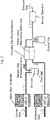
- FIG. 2 A configuration example of a gas measurement device capable of performing the above-described measurement is conceptually shown in Fig. 2 .
- a humidity equilibration device that equilibrates the humidity of the reference gas and the humidity of the sample gas, as described above, is inserted into the conceptual illustration of the conventional gas measurement device shown in Fig. 1 .
- a water vapor permeable membrane is arranged between a flow path of the reference gas and a flow path of the sample gas. Water vapor moves from a high humidity side to a low humidity side via the water vapor permeable membrane, and the humidities of both gases thereby asymptotically approach an equilibrium state. Note that in Fig.
- the humidity equilibration device is drawn to have a simple box-like structure the inside of which is divided by a partition wall (water vapor permeable membrane) on a plane, but this is a conceptual structural illustration drawn in an extremely simplified manner for the sake of clarity.
- a partition wall water vapor permeable membrane
- various modifications may be made such as increasing the area of the water vapor permeable membrane, for example, by forming the water vapor permeable membrane into a pipe-like structure, and naturally, this kind of any modification remains within the technical scope of the present invention.
- an insertion position of the humidity equilibration device is on the flow paths of the reference gas and the sample gas and in a section where the flow path of the sample gas and the flow path of the reference gas are separated from each other. That is, the insertion position is up to an integration point (the second vial in Fig. 2 ) of the flow paths on a downstream side, and up to a point where the humidity of the sample gas does not substantially change on an upstream side.
- a section from a supply source (not shown) of the carrier gas to the first vial is connected to a flow path on a downstream side of the first vial, and water vapor may be contained in a head space gas in the first vial. Therefore, there is no guarantee that the amount of water vapor contained in the carrier gas on the upstream side is the same as that contained in the sample gas on the downstream side of the first vial.
- the humidity equilibration device is preferably arranged on a downstream side of a place where such a phenomenon occurs.
- any membrane can be used as long as the membrane has water vapor permeability and finally has low permeability and absorbability for a component to be detected in the sample gas enough to achieve a purpose of measurement such as detection or identification of an object to be measured.
- a contact portion may have any specific shape or size.
- humidity equilibrium between the reference gas and the sample gas desirably occurs in a time as short as possible, and in order to avoid an increase in the size of the device, a volume occupied by the contact portion is desirably small.
- Nafion or another perfluorosulfonic acid polymer can be used as a material of the membrane.
- the chemical structural formula of Nafion is shown below.
- Nafion Since Nafion has a complicated nanostructure, causes and the like of the characteristics of Nafion have not been completely clarified. As one model, it is presumed that Nafion forms a cluster in which reverse micelles formed of a perfluoroalkyl ether group having a hydrophilic sulfonic acid and each having a diameter of about 4 nm are connected to each other. A reason why ability to absorb moisture and other protic substances is high despite a high proportion of a hydrophobic moiety is considered to be that ions and water can be transported by this network coated with a sulfonic acid group. Nafion has such characteristics, and is therefore a preferable material as the water vapor permeable membrane used in the present invention.
- a perfluorosulfonic acid polymer other than Nafion can be used similarly.
- perfluorosulfonic acid polymers each having a chemical structure and physical properties similar to Nafion, for example, Flemion (registered trademark) manufactured by Asahi Glass Co., Ltd. and Aciplex (registered trademark) manufactured by Asahi Kasei Corporation are commercially available, and these other perfluorosulfonic acid polymers can also be used similarly.
- a hygroscopic material capable of reversibly absorbing, releasing, and permeating water vapor such as a vinyl alcohol-based polymer film
- a material having a high water vapor absorption, release, and permeation rate is preferable, although not intended to be limited thereto.
- a material that is not hygroscopic such as a hollow fiber membrane or a nanomaterial membrane having a large number of extremely minute pores through which a water molecule passes, can also be used.
- the water vapor permeable membrane is not limited to those formed only of the above materials.
- a material serving as a frame for supporting each of these materials to provide a tough membrane as a whole or a material for forming a composite material modified such that a tough membrane can be easily formed can also be contained in the water vapor permeable membrane.
- the membrane in order to achieve a rapid equilibrium between the reference gas and the sample gas, the membrane preferably has a large area. In order to increase the area of the membrane at a boundary between both gases in a limited space, the membrane desirably has a non-flat three-dimensional shape.
- a structure and shape are often seen in a device for performing gas exchange or heat exchange.
- an additional gas and an additional water vapor permeable membrane may be interposed between the reference gas and the sample gas.
- a gas contact structure of "reference gas / water vapor permeable membrane / third gas / water vapor permeable membrane / sample gas" is formed.
- the humidities of the reference gas and the sample gas when reaching a normal state can be further lowered.
- only one structure of "/ third gas / water vapor permeable membrane /" is arranged, but of course this structure may be repeated a plurality of times.
- the same gas as the reference gas may be used.
- the contact between the reference gas and the sample gas via the water vapor permeable membrane is not direct but indirect in that an additional gas is also interposed therebetween, and a gas to be detected in the sample gas can be thereby prevented or reduced from leaking to the reference gas side.
- all or some of components that have leaked into the third gas can be returned to the original sample gas side.
- permeation of a gas via the water vapor permeable membrane is normally bidirectional, and therefore it is also necessary to take leakage of the third gas to the sample gas side into account. From this point of view, it is often preferable to use the same kind of gas as the reference gas as the third gas. Of course, since there are other measures such as using a gas that is unlikely to permeate the water vapor permeable membrane as the third gas, it should be noted that it is not essential that the third gas is the same kind of gas as the reference gas.
- FIG. 3 An example of a humidity equilibration device having such a tubular structure is shown in Fig. 3 .
- P and P' represent reference gases before and after input thereof into the humidity equilibration device, respectively
- S and S' represent sample gases before and after input thereof into the humidity equilibration device, respectively
- X and X' represent third gases before and after input thereof into the humidity equilibration device, respectively.
- Fig. 3 shows that the sample gas flows through a thin tube, but conversely, the reference gas may flow through a thin tube.
- an inner tube out of the double tubes is formed of the water vapor permeable membrane, and the sample gas and the reference gas flow into a space in the inner tube and a space between the inner and outer tubes, respectively, to equilibrate the humidity of the sample gas and the humidity of the reference gas.
- the volume of the space in the inner tube and the volume of the space between the inner and outer tubes may be substantially the same as each other, or one may be larger than the other.
- the humidity of each of the gases at an outlet of the humidity equilibration device can be an arithmetic average of the original humidity of each of the gases under conditions where the tubes are long enough to reach equilibrium sufficiently.
- the reference gas side is a dry gas
- the humidity of each of the gases at the outlet of the humidity equilibration device can be lower than the arithmetic average value.
- Configuration B in Fig. 3 shows an example of a configuration for performing humidity equilibrium of a type in which the reference gas and the sample gas are indirectly brought into contact with each other via the third gas by arranging the above-described third gas and additional water vapor permeable membrane.
- the reference gas and the sample gas flow into two inner tubes formed of the water vapor permeable membranes, respectively, and a thicker outer tube surrounding both tubes is arranged to cause the third gas to flow into a space between the inner tube and the outer tube.
- water vapor is exchanged between the reference gas and the sample gas in the two inner tubes via the third gas, and humidity equilibrium thereby occurs between both gases.
- a plurality of inner tubes may be arranged inside the outer tube.
- different sample gases may pass through some of the inner tubes, or the kind of sample gas may differ depending on an inner tube.
- a humidity equilibration device for gas measurement for a plurality of sample gases can be integrated.
- a kind of crosstalk between the plurality of inner tubes that is, an influence of erroneous detection caused by passing of a component to be detected in a certain sample gas through the water vapor permeable membrane and entering of the component into another sample gas flowing in another inner tube falls within an error range required for the measurement.
- the humidity equilibration device there is a bundle of tubes or other flow paths, for example, in which figures of a plurality of polygonal shapes such as a honeycomb shape and a lattice shape, a circle, and other various shapes in cross section are joined to each other.
- a structure of a rectangular assembly having adjacent cross sections will be described as an example, it is possible to efficiently equilibrate humidity by preparing a bundle of flow paths in which a plurality of tubes or the like having rectangular cross sections is arranged in parallel (of course, a wall portion between adjacent tubes may be a single wall that partitions a space in the adjacent tubes instead of a double structure in which side walls of the tubes overlap each other) and causing different gases to flow through flow paths having adjacent side surfaces.
- FIG. 4 An example of a more specific structure of the humidity equilibration device shown in configuration A in Fig. 3 formed in this manner is shown in Fig. 4 .
- the sample gas is introduced from a sample gas inlet at the right end of the humidity equilibration device shown as a conceptual illustration, enters a water vapor permeable tube pack arranged inside the humidity equilibration device and obtained by bundling tubes each having a tube wall made of a water vapor permeable material, is divided into a plurality of tubes in the water vapor permeable tube pack, and flows from the right to the left in an outer tube of the humidity equilibration device.
- the reference gas is introduced into the outer tube from a reference gas inlet located near the right end of the water vapor permeable tube pack near the upper right in Fig. 4 , and flows in the same direction as the sample gas in the water vapor permeable tube pack, that is, from the right to the left in Fig. 4 .
- the humidity of the reference gas is lower than the humidity of the sample gas
- water vapor in the sample gas permeates a tube wall of each of tubes of the water vapor permeable tube pack due to a humidity gradient between the sample gas and the reference gas, and enters the reference gas flowing through a space between the water vapor permeable tube pack and the outer tube.
- the amount of such a gas to be detected leaking to the reference gas side cannot be ignored, not only by a decrease in a detection signal level due to a decrease in the amount of a gas to be detected in the sample gas, but also by detection of a gas to be detected in the reference gas, a detection signal level of the gas to be detected in the sample gas is canceled out, which further decreases sensitivity. Therefore, it cannot be said that the larger the area of the water vapor permeable membrane such as the total extension of the water vapor permeable tube is, the better.
- the area of the water vapor permeable membrane is desirably set within an appropriate range in consideration of a balance between the water vapor passing amount and the leakage amount of a gas to be detected.
- gas flows in the sample gas side region and the reference gas side region in the humidity equilibration device are basically pulsatile gas flows that perform on/off operation in phases opposite to each other.
- the efficiency of humidity equilibration by the membrane may decrease, or the efficiency of humidity equilibration may temporally change in synchronization with switching of both gases, and as a result, the humidities of both gases may also temporally change (it should be noted that, conversely, there is a time during which a gas flow stops for a certain period of time, which may increase the efficiency of equilibration).
- the reference gas and the sample gas can be each supplied to the humidity equilibration device at a constant flow rate (an average flow rate of each of the gases supplied to the sensor chamber, or the like), and by arranging a storage of each of the gases on a downstream side of the humidity equilibration device, each of the above-described gases in phases opposite to each other can be periodically fed from the storage toward the sensor chamber.
- a smoothing means such as a gas container that absorbs a pulsation of a flow rate by having a certain volume (which may further have a shape serving as a resistance of a gas flow) upstream or downstream of the humidity equilibration device.
- the humidity equilibration device itself also has a certain volume at a place through which each of the gases passes, and also has resistance to a gas flow due to inclusion of a pipe through which the gases pass. Therefore, the humidity equilibration device itself can also serve as the smoothing means.
- the reference gas, the sample gas, and the like may be each supplied at any flow rate, and not only the temperature, pressure, concentration, and the like of each of the gases at this time can be arbitrarily selected, but also it is not all the time necessary to alternately and repeatedly supply and stop the sample gas and the reference gas, that is, any condition can be applied.
- the humidity sensor is arranged in the sensor (the sensor chamber in the example shown in Fig. 2 ) to which the reference gas and the sample gas are supplied.
- the position where the humidity sensor is arranged is not limited to this position as long as the humidity at the position is the same as that in the sensor chamber.
- such a humidity sensor may be arranged between the integration point of the reference gas and the sample gas and the sensor chamber, an inside of the sensor chamber, or in a downstream side of the sensor chamber as long as the humidity sensor is arranged on an upstream side of a portion where the humidity may change due to mixing of an additional gas or the like.
- the specific gas may be another gas such as oxygen.
- the specific gas has been described assuming that this specific gas can be contained in the sample gas side, but the specific gas may also be contained in both the reference gas and the sample gas or only in the reference gas.
- Example of the present invention in which water vapor is used as an example of the specific gas will be described.
- the present invention is not limited to this Example, and the technical scope of the present invention is determined based on the claims of the present application.
- configuration A shown in Fig. 3 was used as the humidity equilibration device, a Nafion tube was used as the inner tube, and a stainless steel tube was used as the outer tube.
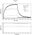
- the sample gas and the reference gas having humidities equilibrated with each other obtained in this manner were supplied to a sensor chamber using MSS as a surface stress sensor. MSS signals thus obtained are shown in Fig. 5 .
- MSS signals thus obtained are shown in Fig. 5 .
- the sample gas "exhaled breath collected in a bag" ("Breath" in Fig.
- FIG. 5 shows a humidity change obtained at the same time. More specifically, the lower graph of Fig. 5 shows signals output from a humidity sensor (not shown in Fig. 3 ) placed in the sensor chamber. Note that the same applies to the lower graph of Fig. 6 . As can be confirmed by the upper and lower graphs, a variation of an output signal due to humidity can be suppressed by using the present device.
- FIG. 6 shows a humidity change obtained simultaneously with the upper graph of Fig. 6 (note that a response time of the humidity sensor used for the measurement is about several seconds, which is considerably slow).
- a response time of the humidity sensor used for the measurement is about several seconds, which is considerably slow.
- the measured humidity is substantially constant during one cycle of the MSS output signal from each of the samples. This indicates that humidity equilibrium is achieved between the reference gas and the sample gas. Furthermore, the graphs of the MSS output signals shown on the upper graph of Fig. 5 indicate that correlation between the amplitude of the output signal and a humidity value shown in the lower graph is clearly smaller than that in Fig. 6 , and furthermore, the waveform of the MSS output signal largely differs depending on a sample.
- the present invention even when a considerable amount of water vapor is contained in a sample gas, it is possible to largely reduce an influence of water vapor on a measurement result without measuring the amount of water vapor contained in the original sample gas by performing measurement in which the humidities of a reference gas and the sample gas are equilibrated with each other via a water vapor permeable membrane and then the reference gas and the sample gas are alternately and repeatedly supplied to a sensor such as a surface stress sensor.
- a movable component such as a pump or a valve, an active component, measurement of humidity or the like, and control such as feedback of a result of the measurement are essentially not required. Therefore, since the present invention can reduce a humidity influence while minimizing an increase in size and complexity of a measurement device, the present invention can be largely expected to be used for a portable device, a low-cost device, and the like, although not being limited thereto.
- Patent Literature 1 WO 2011/148774 A
Landscapes
- Chemical & Material Sciences (AREA)
- Life Sciences & Earth Sciences (AREA)
- Health & Medical Sciences (AREA)
- Engineering & Computer Science (AREA)
- Biochemistry (AREA)
- Physics & Mathematics (AREA)
- Analytical Chemistry (AREA)
- General Health & Medical Sciences (AREA)
- General Physics & Mathematics (AREA)
- Immunology (AREA)
- Pathology (AREA)
- Food Science & Technology (AREA)
- Medicinal Chemistry (AREA)
- Combustion & Propulsion (AREA)
- Sampling And Sample Adjustment (AREA)
Applications Claiming Priority (2)
| Application Number | Priority Date | Filing Date | Title |
|---|---|---|---|
| JP2019137069 | 2019-07-25 | ||
| PCT/JP2020/023663 WO2021014835A1 (fr) | 2019-07-25 | 2020-06-17 | Procédé de mesure reposant sur un capteur de gaz et dispositif de mesure |
Publications (3)
| Publication Number | Publication Date |
|---|---|
| EP4006526A1 true EP4006526A1 (fr) | 2022-06-01 |
| EP4006526A4 EP4006526A4 (fr) | 2023-08-23 |
| EP4006526B1 EP4006526B1 (fr) | 2025-01-15 |
Family
ID=74193390
Family Applications (1)
| Application Number | Title | Priority Date | Filing Date |
|---|---|---|---|
| EP20843648.5A Active EP4006526B1 (fr) | 2019-07-25 | 2020-06-17 | Procédé de mesure reposant sur un capteur de gaz et dispositif de mesure |
Country Status (5)
| Country | Link |
|---|---|
| US (1) | US12078627B2 (fr) |
| EP (1) | EP4006526B1 (fr) |
| JP (1) | JP7212337B2 (fr) |
| CN (1) | CN114127557A (fr) |
| WO (1) | WO2021014835A1 (fr) |
Families Citing this family (1)
| Publication number | Priority date | Publication date | Assignee | Title |
|---|---|---|---|---|
| JP7715690B2 (ja) * | 2022-09-06 | 2025-07-30 | 株式会社東芝 | ガスセンサシステム |
Family Cites Families (20)
| Publication number | Priority date | Publication date | Assignee | Title |
|---|---|---|---|---|
| CA2172520C (fr) * | 1994-07-26 | 2006-05-02 | Christopher Barber | Surveillance environnementale de composes organiques |
| JPH0961352A (ja) * | 1995-08-24 | 1997-03-07 | Horiba Ltd | ガス導入装置 |
| JPH11174035A (ja) * | 1997-12-08 | 1999-07-02 | Dkk Corp | ガスクロマトグラフ装置 |
| SE0004140D0 (sv) | 2000-11-13 | 2000-11-13 | Siemens Elema Ab | Acoustic Gas Analyser |
| JP2002202235A (ja) | 2001-01-04 | 2002-07-19 | Horiba Ltd | ガス濃度測定装置 |
| DE10318956A1 (de) * | 2003-04-26 | 2004-11-11 | Kanesho Soil Treatment Bvba | Verfahren und Vorrichtung zum Nachweis von flüchtigen Analyten in Luftproben |
| US20100107735A1 (en) | 2005-09-22 | 2010-05-06 | Igor Pavlovsky | Gas Sensor |
| US7435284B2 (en) * | 2005-11-17 | 2008-10-14 | Thermo Electron Corporation | Parallel-plate diffusion gas dehumidifier and methods for use |
| JP4688672B2 (ja) * | 2005-12-22 | 2011-05-25 | 東亜ディーケーケー株式会社 | ガス分析計 |
| JP2007309770A (ja) * | 2006-05-18 | 2007-11-29 | Hitachi Ltd | 油中ガス分析装置、油中ガス分析装置を備えた変圧器、及び油中ガスの分析方法 |
| GB0902880D0 (en) * | 2009-02-20 | 2009-04-08 | Bedfont Scient Ltd | Apparatus and method |
| DE102010014222B4 (de) * | 2010-04-08 | 2019-03-21 | Drägerwerk AG & Co. KGaA | Druckluftüberwachungseinrichtung |
| WO2011148774A1 (fr) | 2010-05-24 | 2011-12-01 | 独立行政法人物質・材料研究機構 | Capteur de contrainte superficielle |
| US20170065208A1 (en) * | 2014-03-07 | 2017-03-09 | Ngk Spark Plug Co., Ltd. | Respiratory Monitor |
| JP2017213477A (ja) | 2014-10-14 | 2017-12-07 | Agcエンジニアリング株式会社 | 水蒸気選択透過性チューブ |
| PL4218880T3 (pl) | 2016-05-04 | 2026-03-30 | Mallinckrodt Pharmaceuticals Ireland Limited | Urządzenie do regulacji wilgotności próbkowanego gazu z układu oddechowego pacjenta połączone z wentylatorem i/lub układem doprowadzania tlenku azotu |
| CN106644805B (zh) | 2016-10-17 | 2019-03-22 | 吉林大学 | 软粘土结合水含量联合测定装置及方法 |
| EP3633344A4 (fr) | 2017-05-31 | 2021-03-03 | National Institute for Materials Science | Récepteur de capteur nanomécanique constitué d'un matériau à faible hygroscopicité et capteur nanomécanique utilisant celui-ci en tant que récepteur |
| JP2020096801A (ja) * | 2018-10-17 | 2020-06-25 | ザ フェインスタイン インスティトゥーツ フォー メディカル リサーチ | 吸気と呼気の間でのガス濃度差を測定するためのシステムおよび方法 |
| CN109358005A (zh) * | 2018-12-13 | 2019-02-19 | 青岛海纳光电环保有限公司 | 二氧化氮浓度检测装置及方法 |
-
2020
- 2020-06-17 WO PCT/JP2020/023663 patent/WO2021014835A1/fr not_active Ceased
- 2020-06-17 EP EP20843648.5A patent/EP4006526B1/fr active Active
- 2020-06-17 CN CN202080050969.3A patent/CN114127557A/zh active Pending
- 2020-06-17 JP JP2021533865A patent/JP7212337B2/ja active Active
- 2020-06-17 US US17/627,421 patent/US12078627B2/en active Active
Also Published As
| Publication number | Publication date |
|---|---|
| WO2021014835A1 (fr) | 2021-01-28 |
| US20220260540A1 (en) | 2022-08-18 |
| CN114127557A (zh) | 2022-03-01 |
| EP4006526B1 (fr) | 2025-01-15 |
| US12078627B2 (en) | 2024-09-03 |
| JP7212337B2 (ja) | 2023-01-25 |
| JPWO2021014835A1 (fr) | 2021-01-28 |
| EP4006526A4 (fr) | 2023-08-23 |
Similar Documents
| Publication | Publication Date | Title |
|---|---|---|
| Welp et al. | Design and performance of a Nafion dryer for continuous operation at CO 2 and CH 4 air monitoring sites | |
| Scholes et al. | Comparison of thin film composite and microporous membrane contactors for CO2 absorption into monoethanolamine | |
| US5643799A (en) | Process for analyzing CO2 in seawater | |
| US10274457B2 (en) | Gas component concentration measurement device and method for gas component concentration measurement | |
| Ahmad et al. | CO2 removal using membrane gas absorption | |
| FI117179B (fi) | Kaasukromatografi | |
| Ansaloni et al. | Development of membrane contactors using volatile amine-based absorbents for CO2 capture: Amine permeation through the membrane | |
| Słomińska et al. | New developments in preparation and use of standard gas mixtures | |
| JP2017009342A (ja) | 水素ガス濃度の連続測定方法及びそれに用いる水素ガス濃度測定装置 | |
| EP4006526B1 (fr) | Procédé de mesure reposant sur un capteur de gaz et dispositif de mesure | |
| US5910448A (en) | Process for analyzing CO2 in air and in water | |
| KR20180069847A (ko) | 향상된 안정도의 필터 완전성 시험 | |
| US20200057039A1 (en) | Device and method for detecting gas | |
| Comite et al. | Exploring CO2 capture from pressurized industrial gaseous effluents in membrane contactor-based pilot plant | |
| Comite et al. | Rate of CO2 transfer to loaded MEA solutions using a membrane contactor device | |
| JP2010503848A (ja) | 容器および密閉部材のガス透過度測定方法 | |
| Kárászová et al. | Comparison of theoretical and experimental mass transfer coefficients of gases in supported ionic liquid membranes | |
| CN104777090A (zh) | 透氧分析测试仪 | |
| US11761893B2 (en) | Water vapor differential minimization systems and methods for gas exchange measurements of aqueous or water saturated samples | |
| JPH07113605B2 (ja) | ガス分析計 | |
| US9074972B2 (en) | Surrogate addition device and a method of analyte concentration | |
| Modelski et al. | Kinetics of VOC absorption using capillary membrane contactor | |
| Meireles et al. | Evaluation of hybrid polysaccharide membranes for gas dehydration using on-line mass spectrometry | |
| Fraga | Characterisation of Transient Transport In Dense Membranes Using On-line Mass Spectrometry | |
| US6368559B1 (en) | Device for analyzing organic compounds particularly in aqueous and gaseous samples |
Legal Events
| Date | Code | Title | Description |
|---|---|---|---|
| STAA | Information on the status of an ep patent application or granted ep patent |
Free format text: STATUS: THE INTERNATIONAL PUBLICATION HAS BEEN MADE |
|
| PUAI | Public reference made under article 153(3) epc to a published international application that has entered the european phase |
Free format text: ORIGINAL CODE: 0009012 |
|
| STAA | Information on the status of an ep patent application or granted ep patent |
Free format text: STATUS: REQUEST FOR EXAMINATION WAS MADE |
|
| 17P | Request for examination filed |
Effective date: 20220119 |
|
| AK | Designated contracting states |
Kind code of ref document: A1 Designated state(s): AL AT BE BG CH CY CZ DE DK EE ES FI FR GB GR HR HU IE IS IT LI LT LU LV MC MK MT NL NO PL PT RO RS SE SI SK SM TR |
|
| DAV | Request for validation of the european patent (deleted) | ||
| DAX | Request for extension of the european patent (deleted) | ||
| A4 | Supplementary search report drawn up and despatched |
Effective date: 20230726 |
|
| RIC1 | Information provided on ipc code assigned before grant |
Ipc: G01N 33/00 20060101ALI20230720BHEP Ipc: G01N 5/02 20060101ALI20230720BHEP Ipc: G01N 19/00 20060101AFI20230720BHEP |
|
| STAA | Information on the status of an ep patent application or granted ep patent |
Free format text: STATUS: EXAMINATION IS IN PROGRESS |
|
| 17Q | First examination report despatched |
Effective date: 20240419 |
|
| GRAP | Despatch of communication of intention to grant a patent |
Free format text: ORIGINAL CODE: EPIDOSNIGR1 |
|
| STAA | Information on the status of an ep patent application or granted ep patent |
Free format text: STATUS: GRANT OF PATENT IS INTENDED |
|
| INTG | Intention to grant announced |
Effective date: 20241018 |
|
| GRAS | Grant fee paid |
Free format text: ORIGINAL CODE: EPIDOSNIGR3 |
|
| GRAA | (expected) grant |
Free format text: ORIGINAL CODE: 0009210 |
|
| STAA | Information on the status of an ep patent application or granted ep patent |
Free format text: STATUS: THE PATENT HAS BEEN GRANTED |
|
| AK | Designated contracting states |
Kind code of ref document: B1 Designated state(s): AL AT BE BG CH CY CZ DE DK EE ES FI FR GB GR HR HU IE IS IT LI LT LU LV MC MK MT NL NO PL PT RO RS SE SI SK SM TR |
|
| REG | Reference to a national code |
Ref country code: CH Ref legal event code: EP Ref country code: GB Ref legal event code: FG4D |
|
| REG | Reference to a national code |
Ref country code: DE Ref legal event code: R096 Ref document number: 602020044946 Country of ref document: DE |
|
| REG | Reference to a national code |
Ref country code: IE Ref legal event code: FG4D |
|
| REG | Reference to a national code |
Ref country code: NL Ref legal event code: MP Effective date: 20250115 |
|
| PG25 | Lapsed in a contracting state [announced via postgrant information from national office to epo] |
Ref country code: NL Free format text: LAPSE BECAUSE OF FAILURE TO SUBMIT A TRANSLATION OF THE DESCRIPTION OR TO PAY THE FEE WITHIN THE PRESCRIBED TIME-LIMIT Effective date: 20250115 |
|
| PG25 | Lapsed in a contracting state [announced via postgrant information from national office to epo] |
Ref country code: RS Free format text: LAPSE BECAUSE OF FAILURE TO SUBMIT A TRANSLATION OF THE DESCRIPTION OR TO PAY THE FEE WITHIN THE PRESCRIBED TIME-LIMIT Effective date: 20250415 |
|
| PG25 | Lapsed in a contracting state [announced via postgrant information from national office to epo] |
Ref country code: FI Free format text: LAPSE BECAUSE OF FAILURE TO SUBMIT A TRANSLATION OF THE DESCRIPTION OR TO PAY THE FEE WITHIN THE PRESCRIBED TIME-LIMIT Effective date: 20250115 |
|
| PG25 | Lapsed in a contracting state [announced via postgrant information from national office to epo] |
Ref country code: PL Free format text: LAPSE BECAUSE OF FAILURE TO SUBMIT A TRANSLATION OF THE DESCRIPTION OR TO PAY THE FEE WITHIN THE PRESCRIBED TIME-LIMIT Effective date: 20250115 |
|
| PGFP | Annual fee paid to national office [announced via postgrant information from national office to epo] |
Ref country code: DE Payment date: 20250618 Year of fee payment: 6 |
|
| PG25 | Lapsed in a contracting state [announced via postgrant information from national office to epo] |
Ref country code: ES Free format text: LAPSE BECAUSE OF FAILURE TO SUBMIT A TRANSLATION OF THE DESCRIPTION OR TO PAY THE FEE WITHIN THE PRESCRIBED TIME-LIMIT Effective date: 20250115 |
|
| REG | Reference to a national code |
Ref country code: LT Ref legal event code: MG9D |
|
| PG25 | Lapsed in a contracting state [announced via postgrant information from national office to epo] |
Ref country code: IS Free format text: LAPSE BECAUSE OF FAILURE TO SUBMIT A TRANSLATION OF THE DESCRIPTION OR TO PAY THE FEE WITHIN THE PRESCRIBED TIME-LIMIT Effective date: 20250515 Ref country code: NO Free format text: LAPSE BECAUSE OF FAILURE TO SUBMIT A TRANSLATION OF THE DESCRIPTION OR TO PAY THE FEE WITHIN THE PRESCRIBED TIME-LIMIT Effective date: 20250415 |
|
| REG | Reference to a national code |
Ref country code: AT Ref legal event code: MK05 Ref document number: 1760122 Country of ref document: AT Kind code of ref document: T Effective date: 20250115 |
|
| PG25 | Lapsed in a contracting state [announced via postgrant information from national office to epo] |
Ref country code: HR Free format text: LAPSE BECAUSE OF FAILURE TO SUBMIT A TRANSLATION OF THE DESCRIPTION OR TO PAY THE FEE WITHIN THE PRESCRIBED TIME-LIMIT Effective date: 20250115 |
|
| PG25 | Lapsed in a contracting state [announced via postgrant information from national office to epo] |
Ref country code: LV Free format text: LAPSE BECAUSE OF FAILURE TO SUBMIT A TRANSLATION OF THE DESCRIPTION OR TO PAY THE FEE WITHIN THE PRESCRIBED TIME-LIMIT Effective date: 20250115 Ref country code: PT Free format text: LAPSE BECAUSE OF FAILURE TO SUBMIT A TRANSLATION OF THE DESCRIPTION OR TO PAY THE FEE WITHIN THE PRESCRIBED TIME-LIMIT Effective date: 20250515 |
|
| PGFP | Annual fee paid to national office [announced via postgrant information from national office to epo] |
Ref country code: FR Payment date: 20250627 Year of fee payment: 6 |
|
| PG25 | Lapsed in a contracting state [announced via postgrant information from national office to epo] |
Ref country code: BG Free format text: LAPSE BECAUSE OF FAILURE TO SUBMIT A TRANSLATION OF THE DESCRIPTION OR TO PAY THE FEE WITHIN THE PRESCRIBED TIME-LIMIT Effective date: 20250115 Ref country code: GR Free format text: LAPSE BECAUSE OF FAILURE TO SUBMIT A TRANSLATION OF THE DESCRIPTION OR TO PAY THE FEE WITHIN THE PRESCRIBED TIME-LIMIT Effective date: 20250416 |
|
| PG25 | Lapsed in a contracting state [announced via postgrant information from national office to epo] |
Ref country code: AT Free format text: LAPSE BECAUSE OF FAILURE TO SUBMIT A TRANSLATION OF THE DESCRIPTION OR TO PAY THE FEE WITHIN THE PRESCRIBED TIME-LIMIT Effective date: 20250115 |
|
| PG25 | Lapsed in a contracting state [announced via postgrant information from national office to epo] |
Ref country code: SE Free format text: LAPSE BECAUSE OF FAILURE TO SUBMIT A TRANSLATION OF THE DESCRIPTION OR TO PAY THE FEE WITHIN THE PRESCRIBED TIME-LIMIT Effective date: 20250115 |
|
| PG25 | Lapsed in a contracting state [announced via postgrant information from national office to epo] |
Ref country code: SM Free format text: LAPSE BECAUSE OF FAILURE TO SUBMIT A TRANSLATION OF THE DESCRIPTION OR TO PAY THE FEE WITHIN THE PRESCRIBED TIME-LIMIT Effective date: 20250115 |
|
| PG25 | Lapsed in a contracting state [announced via postgrant information from national office to epo] |
Ref country code: DK Free format text: LAPSE BECAUSE OF FAILURE TO SUBMIT A TRANSLATION OF THE DESCRIPTION OR TO PAY THE FEE WITHIN THE PRESCRIBED TIME-LIMIT Effective date: 20250115 |
|
| PG25 | Lapsed in a contracting state [announced via postgrant information from national office to epo] |
Ref country code: IT Free format text: LAPSE BECAUSE OF FAILURE TO SUBMIT A TRANSLATION OF THE DESCRIPTION OR TO PAY THE FEE WITHIN THE PRESCRIBED TIME-LIMIT Effective date: 20250115 |
|
| REG | Reference to a national code |
Ref country code: DE Ref legal event code: R097 Ref document number: 602020044946 Country of ref document: DE |
|
| PG25 | Lapsed in a contracting state [announced via postgrant information from national office to epo] |
Ref country code: CZ Free format text: LAPSE BECAUSE OF FAILURE TO SUBMIT A TRANSLATION OF THE DESCRIPTION OR TO PAY THE FEE WITHIN THE PRESCRIBED TIME-LIMIT Effective date: 20250115 Ref country code: EE Free format text: LAPSE BECAUSE OF FAILURE TO SUBMIT A TRANSLATION OF THE DESCRIPTION OR TO PAY THE FEE WITHIN THE PRESCRIBED TIME-LIMIT Effective date: 20250115 |
|
| PG25 | Lapsed in a contracting state [announced via postgrant information from national office to epo] |
Ref country code: RO Free format text: LAPSE BECAUSE OF FAILURE TO SUBMIT A TRANSLATION OF THE DESCRIPTION OR TO PAY THE FEE WITHIN THE PRESCRIBED TIME-LIMIT Effective date: 20250115 |
|
| PG25 | Lapsed in a contracting state [announced via postgrant information from national office to epo] |
Ref country code: SK Free format text: LAPSE BECAUSE OF FAILURE TO SUBMIT A TRANSLATION OF THE DESCRIPTION OR TO PAY THE FEE WITHIN THE PRESCRIBED TIME-LIMIT Effective date: 20250115 |
|
| PLBE | No opposition filed within time limit |
Free format text: ORIGINAL CODE: 0009261 |
|
| STAA | Information on the status of an ep patent application or granted ep patent |
Free format text: STATUS: NO OPPOSITION FILED WITHIN TIME LIMIT |
|
| REG | Reference to a national code |
Ref country code: CH Ref legal event code: L10 Free format text: ST27 STATUS EVENT CODE: U-0-0-L10-L00 (AS PROVIDED BY THE NATIONAL OFFICE) Effective date: 20251126 |
|
| 26N | No opposition filed |
Effective date: 20251016 |
|
| REG | Reference to a national code |
Ref country code: CH Ref legal event code: H13 Free format text: ST27 STATUS EVENT CODE: U-0-0-H10-H13 (AS PROVIDED BY THE NATIONAL OFFICE) Effective date: 20260127 |
|
| PG25 | Lapsed in a contracting state [announced via postgrant information from national office to epo] |
Ref country code: MC Free format text: LAPSE BECAUSE OF FAILURE TO SUBMIT A TRANSLATION OF THE DESCRIPTION OR TO PAY THE FEE WITHIN THE PRESCRIBED TIME-LIMIT Effective date: 20250115 |
|
| PG25 | Lapsed in a contracting state [announced via postgrant information from national office to epo] |
Ref country code: LU Free format text: LAPSE BECAUSE OF NON-PAYMENT OF DUE FEES Effective date: 20250617 |
|
| GBPC | Gb: european patent ceased through non-payment of renewal fee |
Effective date: 20250617 |
|
| REG | Reference to a national code |
Ref country code: BE Ref legal event code: MM Effective date: 20250630 |
|
| PG25 | Lapsed in a contracting state [announced via postgrant information from national office to epo] |
Ref country code: GB Free format text: LAPSE BECAUSE OF NON-PAYMENT OF DUE FEES Effective date: 20250617 |
|
| PG25 | Lapsed in a contracting state [announced via postgrant information from national office to epo] |
Ref country code: IE Free format text: LAPSE BECAUSE OF NON-PAYMENT OF DUE FEES Effective date: 20250617 |
|
| PG25 | Lapsed in a contracting state [announced via postgrant information from national office to epo] |
Ref country code: BE Free format text: LAPSE BECAUSE OF NON-PAYMENT OF DUE FEES Effective date: 20250630 |
|
| PG25 | Lapsed in a contracting state [announced via postgrant information from national office to epo] |
Ref country code: CH Free format text: LAPSE BECAUSE OF NON-PAYMENT OF DUE FEES Effective date: 20250630 |