EP4006650B1 - Auf rollen federnder uhranzeigemechanismus - Google Patents
Auf rollen federnder uhranzeigemechanismus Download PDFInfo
- Publication number
- EP4006650B1 EP4006650B1 EP20210222.4A EP20210222A EP4006650B1 EP 4006650 B1 EP4006650 B1 EP 4006650B1 EP 20210222 A EP20210222 A EP 20210222A EP 4006650 B1 EP4006650 B1 EP 4006650B1
- Authority
- EP
- European Patent Office
- Prior art keywords
- roller
- lever
- display
- hour
- correction
- Prior art date
- Legal status (The legal status is an assumption and is not a legal conclusion. Google has not performed a legal analysis and makes no representation as to the accuracy of the status listed.)
- Active
Links
Images


Classifications
-
- G—PHYSICS
- G04—HOROLOGY
- G04B—MECHANICALLY-DRIVEN CLOCKS OR WATCHES; MECHANICAL PARTS OF CLOCKS OR WATCHES IN GENERAL; TIME PIECES USING THE POSITION OF THE SUN, MOON OR STARS
- G04B19/00—Indicating the time by visual means
- G04B19/20—Indicating by numbered bands, drums, discs, or sheets
- G04B19/21—Drums
-
- G—PHYSICS
- G04—HOROLOGY
- G04B—MECHANICALLY-DRIVEN CLOCKS OR WATCHES; MECHANICAL PARTS OF CLOCKS OR WATCHES IN GENERAL; TIME PIECES USING THE POSITION OF THE SUN, MOON OR STARS
- G04B19/00—Indicating the time by visual means
- G04B19/22—Arrangements for indicating different local apparent times; Universal time pieces
-
- G—PHYSICS
- G04—HOROLOGY
- G04B—MECHANICALLY-DRIVEN CLOCKS OR WATCHES; MECHANICAL PARTS OF CLOCKS OR WATCHES IN GENERAL; TIME PIECES USING THE POSITION OF THE SUN, MOON OR STARS
- G04B19/00—Indicating the time by visual means
- G04B19/24—Clocks or watches with date or week-day indicators, i.e. calendar clocks or watches; Clockwork calendars
- G04B19/243—Clocks or watches with date or week-day indicators, i.e. calendar clocks or watches; Clockwork calendars characterised by the shape of the date indicator
- G04B19/257—Clocks or watches with date or week-day indicators, i.e. calendar clocks or watches; Clockwork calendars characterised by the shape of the date indicator drum-shaped or three-dimensional shaped
-
- G—PHYSICS
- G04—HOROLOGY
- G04B—MECHANICALLY-DRIVEN CLOCKS OR WATCHES; MECHANICAL PARTS OF CLOCKS OR WATCHES IN GENERAL; TIME PIECES USING THE POSITION OF THE SUN, MOON OR STARS
- G04B27/00—Mechanical devices for setting the time indicating means
-
- G—PHYSICS
- G04—HOROLOGY
- G04B—MECHANICALLY-DRIVEN CLOCKS OR WATCHES; MECHANICAL PARTS OF CLOCKS OR WATCHES IN GENERAL; TIME PIECES USING THE POSITION OF THE SUN, MOON OR STARS
- G04B27/00—Mechanical devices for setting the time indicating means
- G04B27/005—Mechanical devices for setting the time indicating means stepwise or on determined values
-
- G—PHYSICS
- G04—HOROLOGY
- G04B—MECHANICALLY-DRIVEN CLOCKS OR WATCHES; MECHANICAL PARTS OF CLOCKS OR WATCHES IN GENERAL; TIME PIECES USING THE POSITION OF THE SUN, MOON OR STARS
- G04B13/00—Gearwork
- G04B13/02—Wheels; Pinions; Spindles; Pivots
Definitions
- the invention relates to a jumping roller clock display mechanism.
- the invention also relates to a timepiece, in particular a watch, comprising at least one movement arranged to drive cams included in such a jumping roller timepiece display mechanism.
- the invention relates to the field of watch display mechanisms.
- the invention aims to develop a roller display for an instantaneous jump watch, thus offering the best guarantees of display, and reasonable size, compatible with the volume of a watch.
- the invention is disclosed for the particular case of a watch for a space mission to the planet Mars, where the main display concerns the terrestrial time, while the secondary roller display concerns the Martian time.
- the invention relates to a jumping roller clock display mechanism according to claim 1.
- the invention also relates to a timepiece, in particular a watch, comprising at least one movement arranged to drive cams included in such a jumping roller timepiece display mechanism.
- the invention relates to a jumping roller clock display mechanism 100.
- This mechanism 100 is an instantaneous jumping mechanism.
- this display mechanism 100 is designed to be integrated into a timepiece, in particular a watch 1000, and constitutes more particularly, in a non-limiting embodiment, a module, of reduced dimensions, with in particular a diameter of the order of 37 mm and a height of approximately 12 mm, and illustrated here in a non-limiting application to the display of hours on two digits and minutes on two digits.
- the height constraint determines certain construction choices, which are detailed below, for application to a watch; the mechanism can naturally be simplified in the case of a clock where the dimensional constraints are less.
- the display mechanism is separate from the base movement, and may in particular constitute an independent additional module.
- the mechanism may integrate all or part of the base movement, for example under the return springs of the scales, which will be presented later.
- the mechanism 100 comprises, for displaying a quantity, at least one display which comprises a roller 1, 1A, 1B, 2, 3, 3A, 3B, 4, and/or a combined roller 10.
- Such a combined roller 10 comprises at least two rollers 1A, 1B, 3A, 3B, which are internal to each other, the roller which is external 1A, 3A, comprising at least one roller window 1C, 3C, which is arranged to allow the viewing or reading of the roller which is internal 1B, 3B.
- the rollers or combined rollers comprise numbers or the like with a height of 2.8 mm, which is compatible with six-position rollers with an external diameter of 6.60 mm, or 6.00 mm for an internal roller in the case of a combined roller. This arrangement makes it possible to ensure readability and to minimize the bulk.
- Displaying a digit requires ten positions, for example positions 0/1/2/3/4 on the inner reel, and positions 5/6/7/8/9 on the outer reel, or five positions on each of the reels.
- each roller 1, 1A, 1B, 2, 3, 3A, 3B, 4, or each combined roller 10 has at most six display positions, so as to ensure good readability for the user.
- the outer roller can have a window instead of a display position, and the inner roller can advantageously have the zero position twice, according to the arrangement 0/1/2/3/4/0, which makes it possible to simplify the kinematics as will be seen later.
- the outer roller can have the arrangement 5/6/7/8/9/(), the latter symbol () corresponding to the window opening.
- Each display is held in the rest position by first elastic return means 311, 312, 313, 314, 316, as detailed below.
- At least one display is movable according to a rotation controlled by the movement of at least one trigger or correction lever 11, 12, 13, 14, 15, 16, which the mechanism 100 comprises, when this lever jumps.
- the fall of this trigger lever is controlled or prevented by at least one cam 21, 22, 23, 24, 244, 245, 246, 247, which the mechanism 100 comprises, and which is arranged to be driven by a clockwork movement.
- At least one trigger or correction lever 11, 12, 13, 14, 15, 16 is arranged to cooperate simultaneously with at least two cams 21, 22, 23, 24, 244, 245, 246, 247, towards which it is returned by second elastic return means 119, 129, 139, 149, 159, 169.
- each trigger or correction lever 11, 12, 13, 14, 15, 16 is arranged to cooperate simultaneously with at least two cams 21, 22, 23, 24, 244, 245, 246, 247, towards which it is returned by second elastic return means 119, 129, 139, 149, 159, 169.
- At least two trigger or correction levers 11, 12, 13, 14, 15, 16 are arranged to cooperate simultaneously in support with the same cam 21, 22, 23, 24, 244, 245, 246, 247, towards which they are returned by second elastic return means 119, 129, 139, 149, 159, 169.
- the mechanism 100 comprises at least one trigger lever 11, 12, 13, 14, comprising a first feeler 2111, 2112, 2313, 2314, which is arranged to follow the contour of a rotation control cam 21, 23, which is arranged to cause a jump of a trigger lever 11, 12, 13, 14, in a particular angular position of this rotation control cam 21, 23.
- At least one trigger lever 11, 12, 13, 14 is arranged to cooperate simultaneously in support with at least two cams 21, 22, 23, 24, 244, 245, 246, 247, towards which it is returned by second elastic return means 119, 129, 139, 149. More particularly still, each trigger lever 11, 12, 13, 14 is arranged to cooperate simultaneously in support with at least two cams 21, 22, 23, 24, 244, 245, 246, 247, towards which it is returned by second elastic return means 119, 129, 139, 149.
- At least one triggering rocker 11, 12, 13, 14, is arranged to prohibit or authorize the fall of another rocker which is a correction rocker 15, 16. More particularly, at least one correction rocker 15, 16 is arranged to control the rotation of the same roller as controls a trigger rocker 11, 12, 13, 14.
- At least one correction lever 15, 16 is arranged to control alone the rotation of a roller which does not cooperate with any said trigger lever 11, 12, 13, 14.
- the mechanism 100 comprises at least one prohibiting cam 22, 24, 244, 245, 246, 247, which is arranged to prohibit or authorize the fall of such a triggering or correction lever 11, 12, 13, 14, 15, 16, of which a second feeler 2211, 2212, 2413, 2414, 2415, 2416, is arranged to interfere or not with the prohibiting cam 22, 24, 244, 245, 246, 247, depending on the angular position of this prohibiting cam 22, 24, 244, 245, 246, 247.
- At least one roller 1, 1A, 1B, 2, 3, 3A, 3B, 4, or combined roller 10 is movable in rotation controlled by a drive mechanism 50M, 50H, independent of the trigger or correction rockers 11, 12, 13, 14, 15, 16, and which is driven by another roller 1, 1A, 1B, 2, 3, 3A, 3B, 4, or combined roller 10.
- This drive mechanism 50M, 50H will be detailed later.
- the mechanism 100 comprises at least one upstream display assembly 200, the rotations of the upstream rollers 1, 2 of which are composed are controlled by upstream triggering rockers 11, 12, and which is arranged to cooperate with a downstream display assembly 300 to which it is juxtaposed and the rotations of the downstream rollers 3, 4 of which are composed are controlled by downstream triggering rockers 13, 14.
- This mechanism 100 comprises at least one such correction rocker 15, 16, which is arranged to cooperate with one of the downstream triggering rockers 13, 14, and a rocker synchronization mechanism 17 between the correction rockers 15, 16, when this mechanism 100 comprises several, for controlling the rotation of at least one display assembly 200.
- the downstream display assembly 300 in its proper positioning at the end of a cycle of the upstream display assembly 200.
- the mechanism 100 is arranged to display the value of at least one quantity on a group of displays 90M, 90H, which comprises at least at least two coaxial displays juxtaposed to each other, each display being constituted by a roller 1, 1A, 1B, 2, 3, 3A, 3B, 4, or by a combined roller 10.
- At least one group of displays 90M, 90H comprises an internal jump control mechanism for triggering the rotation of one of the displays comprised in the group of displays 90M, 90H, at the end of a cycle of another display which is juxtaposed thereto.
- At least one trigger or correction rocker 11, 12, 13, 14, 15, 16 is arranged to cooperate with at least one cam 21, 22, 23, 24, 244, 245, 246, 247, to constitute a jump control mechanism for triggering the rotation of one of the displays at the end of a cycle of another display which is juxtaposed therewith.
- the mechanism 100 is more particularly arranged to display the value of at least one quantity on a group of displays 90M, 90H, comprising at least two coaxial elementary displays juxtaposed to one another, each elementary display being constituted by such a roller 1, 1A, 1B, 2, 3, 3A, 3B, 4, or combined roller 10.
- At least one said group of displays 90M, 90H comprises a drive mechanism 50 for triggering the rotation of one of the displays that this group of displays comprises at the end of a cycle of another display that is juxtaposed to it.
- the mechanism 100 is arranged to display the value of at least two quantities, each quantity being displayed on at least one display or a group of displays 90M, 90H, and all the displays or groups of displays 90M, 90H are coaxial and juxtaposed two by two.
- At least one trigger or correction rocker 11, 12, 13, 14, 15, 16 is arranged to cooperate with at least one cam 21, 22, 23, 24, 244, 245, 246, 247, to constitute a jump control mechanism for triggering the rotation of a display of a group of displays 90M, 90H, at the end of a cycle of another display of another group of displays 90M, 90H, which is juxtaposed thereto.
- the mechanism 100 comprises a roller synchronization mechanism for triggering the rotation of a said downstream display of a group of displays 90M, 90H, at the end of a cycle of another upstream display of another group of displays 90M, 90H, which is juxtaposed thereto.
- This mechanism roller synchronization comprises blocking means 1380, 1490, of each downstream triggering rocker 13, 14, arranged for the rotation control of the downstream display 3, resting on lugs 528, 579, carried by the drive mechanism 50 of the upstream display 2, and the upstream display 2 itself, to block the rotation of each downstream triggering rocker 13, 14, during certain display phases, and to synchronize the jump of these at least two groups of displays 90M, 90H.
- This mechanism roller synchronization comprises blocking means 1380, 1490, of each downstream triggering rocker 13, 14, arranged for the rotation control of the downstream display 3, resting on lugs 528, 579, carried by the drive mechanism 50 of the upstream display 2, and the upstream display 2 itself, to block the rotation of each downstream triggering rocker 13,
- the mechanism 100 is arranged to display the value of at least two quantities on at least two groups of displays 90M, 90H, coaxial and juxtaposed to one another.
- at least one group of displays 90M, 90H comprises at least one trigger or correction rocker 11, 12, 13, 14, 15, 16, which comprises a stop support finger 1390, which is arranged to, in certain relative angular positions, cooperate in stop support with a stop 528 which comprises a roller 1, 1A, 1B, 2, 3, 3A, 3B, 4, of an adjacent group of displays 90M, 90H, to block its rotation during certain display phases, and to synchronize the jump of the at least two groups of displays 90M, 90H.
- the figures illustrate the mechanical digital display of hours and minutes.
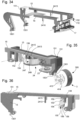
- the display of the minutes is made by a roller of the units of minutes 1, juxtaposed with a roller of the tens of minutes 2, notably visible together through a minute window 5.
- the roller of the units of minutes 1 is such a combined roller 10, and comprises an inner roller 1B, visible through the window 1C of the outer roller 1A, as visible on the figure 3 .
- These two rollers 1 and 2 form a first group of 90M displays which is the group of minute displays.
- the display of the hours is made by a roller of the units of hours 3, juxtaposed with a roller of the tens of hours 4, in particular visible together through an hour window 6.
- the roller of the units of hours 3 is such a combined roller 10, and comprises an inner roller 3B, visible through the window 3C of the outer roller 3A.
- These two rollers 3 and 4 form a second group of displays 90H which is the group of hour displays.
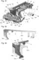
- FIG. 1 illustrates a dial 7 bearing windows 5 and 6 for the minutes and hours, and surmounting a plate 8 which carries the rollers and the other components of the mechanism 100.
- rollers pivot about a common axis R; in a particular and non-limiting manner, the rockers pivot about a common axis B.
- FIG. 3 represents a minute unit roller 1 according to the invention, which is a combined roller 10 which comprises, shown separately from left to right, an inner minute roller 1B, an outer minute roller 1A with its minute aperture 1C, and the assembly 1 consisting of this inner roller 1B mounted in this outer roller 1A.
- the hour unit roller 3 is similarly constructed, with an inner hour roller 3B, an outer hour roller 3A with its aperture 3C.
- At least one group of displays 90M, 90H comprises at least two rollers, one of which displays as a unit an integer multiple of the value of the unit of the other. More particularly still, each group of displays 90M, 90H, comprises at least two rollers, one of which displays as a unit an integer multiple of the value of the unit of the other.
- the display mechanism 100 then comprises, for at least one such group of displays 90M, 90H, at least one drive mechanism 50, for example in the illustrated embodiment a drive mechanism for the tens of minutes 50M, and a drive mechanism for the tens of hours 50H.
- the purpose of this drive mechanism 50 is to rotate the roller of the multiple by one position when the roller of the sub-multiple has completed the rotation, or rotations, corresponding to all of its display sequences in the step of the multiple. Except in exceptional circumstances which will be detailed later, the rollers of the multiples (tens in the present embodiment) are therefore not driven by rockers, but by such a drive mechanism 50.
- This 50 drive mechanism here a 50M tens of minutes drive mechanism, or a 50H tens of hours drive mechanism, is driven by the submultiple roller, here the units roller.
- each group of displays 90M, 90H comprises at least two rollers 1, 1A, 1B, 2, 3, 3A, 3B, 4, kinematically connected by such a drive mechanism 50, which comprises, in the non-limiting version illustrated by the figures, a Maltese cross 53, 55, which is arranged to be driven in rotation by a pin 109, 319, fixed to the roller of the sub-multiple, and which is integral in rotation with a star with lugs 51, 56, which is arranged to drive by one of its lugs 511, 561, a cloverleaf 52, 54, which the roller of the multiple carries, by radial grooves 529, 541.
- a drive mechanism 50 which comprises, in the non-limiting version illustrated by the figures, a Maltese cross 53, 55, which is arranged to be driven in rotation by a pin 109, 319, fixed to the roller of the sub-multiple, and which is integral in rotation with a star with lugs 51, 56, which is arranged to drive by one
- the roller of the sub-multiple drives in rotation a Maltese cross, which drives a star with lugs which in turn drives the roller of the multiple, here tens.
- the unit rollers of minutes 1, and hours 3 thus carry for this purpose respectively pins 109, 319, which are arranged to cooperate with radial grooves 531,551, which include Maltese crosses of minutes 53, or hours 55.
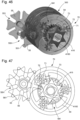
- FIG 4 represents a tens of minutes roller 2, which laterally carries a tens of minutes clover 52, comprising six radial grooves 529, which are arranged to cooperate with a star lug 511 which comprises a star with lugs 51 coupled with a Maltese cross of the minutes 53.
- This tens of minutes clover 52 carries a support lug 528, here in the form of a cubic block, which is arranged to serve as a stop support for a lever limiting finger 1380 which comprises the hour trigger lever of the inner roller 13, as will be explained later.
- the clover 52, 54, or the roller of the multiple carries such a support lug which is arranged to serve as a stop support for a tilt limiting finger which comprises a trigger rocker 11, 12, 13, 14.
- the star with lugs 51, 56, of the drive mechanism 50 of the upstream display 2 is advantageously arranged to drive in rotation, around an axis parallel to its own, a drive cloverleaf 57, which carries a stop lug of rocker 579 arranged to serve as a stop support for a rocker stop finger 1490 which comprises a trigger rocker 11, 12, 13, 14.
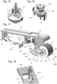
- FIG 5 represents a scroll of tens of hours 4, which similarly bears a clover 54, visible on the figure 45 , and whose shaft includes a drive square 4160, and which laterally carries three tenons 72 or planet carrier pivots for a disengagement mechanism 70 explained later.
- This disengagement mechanism 70 has the function of disengaging a drive mechanism 50, to allow the position correction of a roller 1, 1A, 1B, 2, 3, 3A, 3B, 4, directly by a correction lever 15, 16, and not by a drive mechanism 50.
- the mechanism 100 advantageously comprises at least one combined roller 10, an inner roller 1B, 3B of which is arranged to be driven in rotation by a rocker for triggering the inner roller 11, 13, and the outer roller 1A, 3A of which is arranged to be driven by a rocker for triggering the outer roller 12, 14, or by a first correction rocker 15.
- a combined roller 10 is a sub-multiple roller.
- the inner roller 1B, 3B is, again, arranged to be driven in rotation by the first correction lever 15, at certain predetermined times and controlled by a twenty-four hour mobile 24 driven by the movement 500.
- This first correction lever 15 is juxtaposed with the trigger lever of the inner roller 11, 13, and cooperates with it with the cams of the twenty-four hour mobile 24.
- the first correction lever 15 has a lateral protrusion 151, which rests on a counterbore 135, of the trigger lever of the inner roller 113. This protrusion 151 rests on the counterbore 135, shortly before a jump controlled by a cam 21, 23, on which bears a feeler 2111, 2313, which the trigger lever of the inner roller 11, 13 comprises.
- the correction lever 15 also has a finger drive 1501, which is arranged to take place next to a drive finger 1101, 1301, of the trigger lever of the inner roller 11, 13, and to cooperate with the same star 411, 413, of this inner roller 1B, 3B, so that, when the trigger lever of the inner roller 11, 13 falls, at an instant controlled by the cam 21, 23, and for a jump authorized by the twenty-four hour mobile 24, the first correction lever of the units hour 15 also falls to in turn drive star 411, 413, thus driving the inner roller 1B, 3B twice.
- each roller comprises a shaft, in particular carrying a square, suitable for supporting a star for its rotational drive: we see in particular in the figures the square 4120 for driving roller 1, the square 4140 for roller 3, and the square 4160 for roller 4. It should be noted that certain rollers are not necessarily driven by rockers: this is the case here for the tens of minutes roller 2, which is driven by a 50M tens of minutes drive mechanism with a Maltese cross.
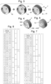
- FIG 6 represents a coding of the display of the minutes, according to which the particular, non-limiting variant of the mechanism is constructed, which is illustrated by the figures, on the basis of the rollers of the Figures 3 and 4 .
- the inner roller 1B, respectively 3B has six positions: 0, 1, 2, 3, 4, 5, 0.
- the outer roller 1A, respectively 3A has six positions: 5, 6, 7, 8, 9, ().
- the double parentheses or brackets are used to code the opening that the roller in question has.
- This particular configuration makes it possible to have the largest numbers in the minimum space requirement, the same drive rocker stroke for both rollers, and the same star-jumper assembly, as can be seen in the figures which include many identical elementary components.
- One line corresponds to one minute.
- the double parentheses or brackets correspond to the opening of the roll.
- the table of the figure 6 only shows the display of minutes “00" to "30", because we notice that there is a periodicity of ten minutes.
- the inner roller 1B when displaying each unit position "5", the inner roller 1B also rotates so as to pre-position itself on the value "0" in order to be ready to display it during the next ten.
- the display of minutes requires a 21 minute cam, and a 22 ten minute cam.
- One line corresponds to one hour.
- the table of the figure 7 shows the display of hours “00” to “24”.
- column 4 and column 5 of this table of hours have a periodicity of twelve hours.
- a single twenty-four hour mobile 24 includes the twelve-hour, twenty-four-hour, and correction cams, as seen on the figure 27 .
- the tens of minutes roller 2 is not connected to a star in the present application; however a different coding of the rollers could require it, in which case its case is to be treated in a similar way to the tens of hours roller 4 for its cooperation with a correction rocker 16 presented later.
- This roller of tens of minutes 2 carries a 52 clover on the side for its drive by a 50M tens drive mechanism with a Maltese cross.
- the tens of hours roller 4 laterally carries a clover 54 similar to that carried by the tens of minutes roller 2, and comprising radial grooves 541; this clover 54 is integral with a self-locking wheel 73 of a disengagement mechanism 70, in the teeth of which satellites 71 can be locked, mounted loosely on the tenons or planet carrier pivots 72 of the figure 5 , to cause the rotation of this roller for tens of hours 4 by clutching this self-locking wheel 73, while the disengagement of the satellites 71 causes the disengagement.
- the unit rollers 1, 3, carry pins 109, 319, which are arranged to cooperate with Maltese crosses of the minutes 53, 55, for the driving of the tens rollers 2, 4, during most of the passages, except for the special passages at certain times, all of which will be detailed later.
- THE figures 9 to 30 show the passage of the minutes. It shows the operation of the minute trigger lever 11, pivoting about a lever axis B, for controlling the inner roller 1B of the combined roller of the minute units 1.
- This lever 11 is subjected to the action of a return spring 119, which tends to press a drive finger 1101, which the lever 11 comprises, on a star 411 which this inner roller 1B comprises, and which is itself subjected to the return torque of a jumper 311 to keep it in the rest position.
- the rocker 11 carries, between its pivot and its distal drive finger 1101, on the one hand a ten-minute feeler finger 2211, which is arranged to cooperate in support with a ten-minute cam 22 which is a straight-edged cam of the crenellation type, and on the other hand a minute feeler roller 2111, which is arranged to bear on the substantially helical track of a minute cam 21, visible in the figure 15 .
- This substantially helical track allows the feeler of each rocker that follows this cam to be raised, before its jump.
- the feeler is in particular a ruby roller or similar, to reduce friction.
- This minute cam 21 includes a device to prevent any recoil at the instant of the jump when the feeler roller 2111 leaves the high point of the cam 21, which is its position on the figure 9 .
- FIG 16 illustrates this device: the cam 21 itself pivots on a cam base 210, a pin 212 secured to the cam 21 slides in a bean-shaped groove 211, which limits the stroke.
- the pin 212 and therefore the cam 21 is ejected tangentially a little further into the groove 211, and lets the rocker 11 fall, and any parasitic recoil movement is avoided.
- FIG 10 illustrates the passage of the minute unit, when the ten-minute feeler finger 2211 is not stopped by the relief of the ten-minute cam 22, and just after the jump of the feeler roller 2111, when the fall of the lever 11 has just driven the star 411 of the roller 1B which has rotated one position.
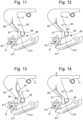
- FIGS. 11 to 14 are details of the cooperation sequence between on the one hand the drive finger 1101, which forms a mobile assembly 80 pivotally mounted on a pivot 84 and which comprises an elastic blade 81 movable between two front 82 and rear 83 stops, and on the other hand the star 411 of the roller 1B.
- the elastic blade 81 rests on a first front stop 82 located on the side of the star 411.
- the rocker 11 descends, the finger 1101 comes into contact with the star 411, the blade 81 leaves the first stop 82 and the finger begins to pivot, its blade 81 approaches the second rear stop 83.
- the star 411 pivots, and the rocker 11 accompanies the star 411 for approximately two thirds of its step before reaching its stop, which ensures the passage of the top of the jumper 311.
- cam of the minutes 21 comprises a substantially helical track, wide enough to be traveled by two feeler rollers 2111 and 2112 which comprise two neighboring rockers 11 and 12.
- FIG 17 shows, together, this minute trigger lever for controlling the inner roller 11, juxtaposed with the minute trigger lever for controlling the outer roller 12, whose feeler rollers 2111 and 2112 thus travel along this same helical track of the cam 21, and whose ten-minute feeler fingers 2211 and 2212 are both arranged to cooperate with the same ten-minute cam 22, which authorizes or prohibits the fall of the respective lever 11 or 12.
- FIG 19 represents the same set represented in the position it occupies a few seconds before the jump, in a display position “04” of the minutes, in reference to the table of the figure 6 , with the display of the unit of minutes “4”, where the outer roller 1A presents its aperture 1C (column 2 of the table), while the inner roller 1B presents the number 4 (column 3 of the table); the mechanism is ready to move to a global display position “05” with a display of the units “5”, where the outer roller 1A presents the number 5 (column 2), while the inner roller 1B returns to a position where it presents the number 0 (column 3) and is thus ready to anticipate the passage to the next ten minutes where the inner roller 1B will present its number 0 in the aperture 1C of the outer roller 1A.
- figure 20 is the situation after the jump, in a display configuration of the value "05" where neither of these two flip-flops 11 and 12 is stopped by the ten-minute cam 22.
- FIG 21 represents the same set after the jump, in another display position, of the value "6", where the inner roller 1B has not rotated and has remained in its display position, because the rocker 11 corresponding to the display of the inner roller 1B is stopped by the ten-minute cam 22, its feeler finger 2211 being in abutment on the slot of the ten-minute cam 22, and as a result the inner roller 1B does not rotate, and only the rocker 12 relating to the outer roller 1A falls and pivots the latter.
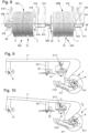
- FIGS. 22 and 23 illustrate the ten-minute drive mechanism 50M, the principle of which is also used for triggering the ten hours in the other group of hour displays 90H.
- This mechanism surrounds the group of displays 90M comprising the combined roller of the units of minutes 1, and the simple roller of the tens of minutes 2; this mechanism is a mobile with an axis parallel to the common axis R of the shafts of the different rollers, and comprises, on the side of the combined roller of the units of minutes 1, a Maltese cross of the minutes 53, the grooves 531 of which are arranged to cooperate with the pin 109, visible on the figure 17 , which this roller 1 carries, and, on the side of the roller of the tens of minutes 2, and integral in rotation with this Maltese cross of the minutes 53, a star with lugs 51 whose lugs 511 are arranged to cooperate with the grooves 529 of the tens of minutes clover 52 of the figure 4 .
- FIG. 24 and 25 illustrate the passage of a decade.
- the figure 24 represents the same assembly, shown in the position it occupies a few seconds before the jump, in global display position "09” with a minute unit display position "9", where the outer roller 1A presents the number 9 (column 2), while the inner roller 1B presents the number 0 (column 3); the mechanism is ready to move to a global display position "10", where the tens roller, until then in the display position "0", will move to the position "1" (column 1), while, at the combined units roller 1, the outer roller 1A will present its aperture 1C (column 2) through which the inner roller 1B will continue, without rotation, to present the display "0" (column 3); a groove 531 of the Maltese cross of the minutes 53 of the minute units cooperates with the pin 109 of the units roller 1.
- figure 25 represents the same assembly after the jump, in an overall display configuration "10" where neither of the two rockers 11, 12, is stopped by the ten-minute cam 22; the outer roller 1A of the combined roller of the minute units 1 has pivoted, and its pin 109 has caused the Maltese cross of the minutes 53 to rotate, which, at the other end, has caused the rotation of the ten-minute cloverleaf 52, and therefore of the ten-minute roller 2.
- the display and passage of the hours is done in a similar manner.
- the group of hour displays 90H comprises a roller displaying units of hours 3, and a roller displaying tens of hours 4.
- a drive mechanism for the tens of hours 50H surrounds this group of displays 90H, as in the case of the minutes, and operates in a similar manner to that of the minutes;
- a rocker for triggering the hours of the inner roller 13 and a rocker for triggering the hours of the outer roller 14 are also juxtaposed, and are arranged to cooperate with a single hour cam 23, and with a combined twenty-four hour mobile 24, which notably comprises a twenty-four hour cam and a twelve hour cam.
- the operation of the passages of the hours is similar to the passage of the minutes described above, the only important variation being the presence of a twelve hour cam, instead of a ten minute cam.
- the invention can be used for any combination of displays, one of which displays a multiple of the other, and for any display range.
- the coding of the different rollers, and the nature of the cams and correction levers are to be adapted to each specific case.
- the rollers can occupy four, or six, or ten, or even twelve positions
- the multiplier coefficient between two rollers of the same group of displays can also be four, or six, or ten, twelve positions, or other, for other displays such as the calendar, moon phases, tides, or other.
- the drive mechanism 50 can also generate the drive of the multiple roller with coefficients different from ten, for example four, six, twelve, or other.
- the twenty-four hour mobile 24 here groups together a first twelve hour cam 244 of the trigger lever of the inner hour roller 13, a second twelve hour cam 245 of the trigger lever of the outer hour roller 14, and a twenty-four hour cam 246, and a correction cam 247, for the management of certain time changes: midnight, one o'clock in the morning, and in particular to guarantee the change from the display "4" to the display "0".
- This correction cam cooperates with correction levers 15 and 16 detailed later.
- the invention requires the presence of a synchronization mechanism between the display of the minutes and that of the hours, in particular at current times, i.e. other than midnight.
- the mechanical system transmits the instantaneousness of the jump from the units roll to the tens roll, both for the hours and for the minutes, thanks to the respective tens drive mechanism by Maltese cross, clover with lugs, and drive clover.
- the trigger rocker of the inner roller of the hour units 13 and the trigger rocker of the outer roller of the hour units 14 driving the two rollers 3B and 3A of the hour units fall a few minutes before the passage of the hour on lugs to standby.
- FIG. 28 thus represents, a few minutes before a time change, the triggering switch of the inner roller of hour units 13, which is similar to the trigger lever of the inner roller of the minute units 11, and whose feeler finger 2313 has just left the hour cam 23.
- This trigger lever of the inner roller of the hour units 13 comprises a second lever limiting finger 1380, which is arranged to cooperate in abutment with a lug 528 which comprises the clover 52 of the tens of minutes roller 2, which prevents the fall of the trigger lever of the inner roller of the hour units 13 until the tens of minutes roller 2 has completed its rotation.
- the figure 29 represents, at the same time as the figure 28 , the same mechanism, the trigger lever of the inner roller of the hour units 13 of which is not shown, in order to allow the vision of the trigger lever of the outer roller of the hour units 14, the feeler finger 2314 of which has also just left the hour cam 23;
- this trigger lever of the outer roller of the hour units 14 also comprises a second lever stop finger 1490, which is arranged to cooperate in stop support with a lug 579 which comprises a drive cloverleaf 57, kinematically linked to the Maltese cross system of the minutes, and which, in the same way, prevents the fall of the trigger lever of the outer roller of the hour units 14 until the Maltese cross of the minutes 53 has completed its rotation.
- the drive cloverleaf 57 is in particular rotatably mounted on a shaft parallel to that of the Maltese cross of the minutes 53, as visible on the figure 29 .
- FIG 31 shows the entire mechanism relating to the hours, which incorporates a correcting lever for the units of the hour 15 which is juxtaposed with the trigger lever for the inner roller of the units of the hour 13, and a correcting lever for the tens of the hour 16 which is juxtaposed with the trigger lever for the outer roller of the units of the hour 14; the assembly is shown in position at 23:59.
- This figure also shows the two tens drive mechanisms.
- the table of the figure 7 shows that the passage of the tens of hours, in particular from the position "23" to the position "00”, does not follow the classic pattern of the passages from “03" to "04” and from "13” to "14", because if the same logic were followed, the change of display would go from “23” to "24” whereas one wants to display "00” permanently, and not “24", for the displays in the first hour of the morning; this does not exclude a variant with a very brief transient display "24""00", between the normal displays "23”"59” and "00""00", which each remain visible for about one minute.
- the Figures 32 and 33 represent the correction lever of the hour units 15, which has a lateral protrusion 151, which rests on a counterbore 135 of the trigger lever of the inner roller of the hour units 13, the protrusion 151 rests on the counterbore 135 a few minutes before the jump, it is then on standby.
- the correction lever of the hour units 15 has a drive finger 1501, which is arranged to take place next to the drive finger 1301 of the trigger lever of the inner roller of the hour units 13, and to cooperate with the same star 413 for driving the inner roller of the hour units 3B.
- this correction lever of the hour units 15 also falls when passing at midnight, which makes it possible to drive the inner roller of the hours 3B twice, and to allow the passage from the display "3" to the display "0", without passing through the display "4"; the same is true at one o'clock in the morning, as visible on the table of the figure 7 .
- FIG 34 represents, together, the 15 hour units correction lever, and the 16 hour tens correction lever, which constitute an arrangement allowing, at midnight, the change from the “2” display to the “0” display, without the tens drive mechanism coming into operation via the Maltese cross 55.
- This 16 hour tens correction lever falls a few minutes before midnight, and relies on the 15 hour units correction lever, by means of a synchronizer which is a shaft 17 carried by the tens of hour correction lever 16, which is parallel to the pivot axis B common to the levers, and of which a bearing surface 172 cooperates with a bearing face 152 of the units of hour correction lever 15.
- This figure 34 shows, again, the feeler fingers 2415 and 2416 of these two scales 15 and 16, which are both arranged to cooperate with the twenty-four hour mobile 24 which authorizes or prohibits the fall of these scales.
- a correction lever 15 carries a pivoting hook 154, which cooperates with a hook actuator 138 carried by the trigger lever 11, 13, for driving this inner roller 1B, 3B, so that, at the end of the travel of the trigger lever 13, its hook actuator 138 releases the hook 154, and authorizes the fall of the correction lever 15, which is released by the twenty-four hour mobile 24, for driving the inner roller 1B, 3B.
- FIG 35 represents, together and juxtaposed, the trigger lever for the inner hour roller 13, and the hour unit correction lever 15, the combination of which allows particular display passages, including the direct passage of the inner hour roller 3B from position “3" to position "0” without rotation of the outer roller 3A, and the passage of the tens of hour roller from position "2" to position "0” without rotating the Maltese cross of the hours 55 of the tens drive mechanism.
- the hour unit correction lever 15 carries a pivoting hook 154, which cooperates with a hook actuator 138 carried by the trigger lever for the inner hour roller 13.
- the hour unit correction lever 15 comprises a feeler finger 2415, which is arranged to cooperate with the combined twenty-four-hour wheel set 24, and in particular with its outer track; the passage from position “3” to position “4” is conventionally controlled by the drive finger 1301 of the trigger lever for the inner hour roller 13 while the hour unit correction lever 15 is immobilized by this hook 154.
- the hook actuator 138 is arranged to push an oblique track 158 of the pivoting hook 154.
- the rocker 15 carries a pin support finger 152 which carries a locking pin 156, which cooperates with a cylindrical track 155 of the hook 154 during a part of the angular travel of the latter, and which escapes from it at the end of the angular travel of the hook under the thrust of the hook actuator 138.
- the hook actuator 138 is resting on the oblique track 158 of the hook 154, and neither of the two rockers 13 and 15 has pivoted.
- figure 38 illustrates the start of the fall of the trigger lever for the inner roller of the hours 13, for the passage from the position "3" to the position "4"; the hook actuator 138 pushes back the oblique track 158, and pivots the hook 154, which still cooperates with its pin 156 at the level of its concentric cylindrical track 155, immobilizing the correction lever of the hour units 15.
- figure 39 illustrates the end of the fall of the trigger lever for the inner roller of the hours 13 for the passage from the position "3" to the position "4"; the hook actuator 138 pushes the oblique track 158 of the hook 154, and pivots the hook 154, which escapes from its pin 156, releasing the correction lever of the hour units 15, which, also released by the twenty-four hour mobile 24, can pivot and drive by its drive finger 1501 the roller inside the hour units 3B, which has just briefly passed to position "4" under the action of the fall of the trigger lever for the inner hour roller 13, towards the "0"position; the twenty-four hour mobile 24 is arranged to allow the fall of the correction lever for the hour units 15 only twice a day, at midnight and at one o'clock in the morning.
- the twenty-four hour cam 247 has a notch 249 corresponding to this time range.
- the correction lever for the hour units 15 remains on the upper part of the twenty-four hour cam 247, which prevents it from falling and prevents it from rotating the star 413 of the inner roller 3B of the hour units.
- the passage of the tens of hours roller 4 from position “2” to position “0” requires the intervention of the tens of hours correction rocker 16, already presented on the figure 34 .
- the tens-hour correction lever 16 cooperates with a twenty-four-hour cam 246, located on the twenty-four-hour mobile 24, to, each day at midnight, release this lever 16 to drive a star 416 linked to the tens-hour roller 4, to move it from position "2" to position "0".
- this clutch release mechanism 70 comprises a self-locking wheel 73 with satellites 71, similar to that of an automatic reverser, to authorize the rotation of the roller of the tens of hours 4 independently of the drive clover linked to the Maltese cross of the hours 55 of the tens drive mechanism, which itself is blocked.
- figure 43 shows the clover 54 of the tens of hours roller 4, under which clover 54 we see this self-locking wheel 73 cooperating with satellites 71, in particular and not limited to three satellites 71 which pivot on three tenons or pivots 72 carried by the tens of hours roller 4.
- FIG 45 illustrates a classic tens passage.
- the outer roller 3A of the hour units passes from the “9” position to the “0” position, it actuates the Maltese cross of the hours 55, which turns the clover 54 secured to the self-locking wheel 73;
- the satellites 71 have a particular non-reversible shape, and lock in the teeth of the self-locking wheel 73, which causes the rotation of the roller of the tens of hours 4;
- the self-locking wheel 73 and the roller of the tens 4 rotate clockwise as seen in the figure, and at least one satellite 71 is in arch-buttress with the teeth of the self-locking wheel 73.
- the clutch release mechanism 70 can take other constructive forms, for example with a freewheel type mechanism, authorizing rotation in one direction, and imposing in the other direction a clutch by blocking a ball on the wall of a chamber in which this ball is enclosed, or other.
- This clutch mechanism 70 can, thus, have two inputs.
- the jumping roller clock display mechanism 100 makes it possible to have, in a small volume, an original display, which can constitute a main display or a secondary display, alone, or in combination or juxtaposition with other displays.
- a particular application describes below a timepiece 1000, in particular a watch, comprising at least one movement 500 for driving a main display mechanism and a secondary display mechanism.
- the example chosen concerns a space mission to the planet Mars: one of the displays is that linked to the planet Earth and to the duration of terrestrial days and hours, while the other display, produced with a jumping roller timepiece display mechanism 100 according to the invention, is linked to the planet Mars, and to the duration of Martian days and hours.
- the duration of a Martian solar day is 24.659790 terrestrial hours (close to 24 hours and 40 terrestrial minutes).
- a suitable timer using mobiles with numbers of teeth reasonable for use in a watch, has a 22-tooth Earth track, which makes one revolution when a 36-tooth timer pinion makes 0.6111 revolutions, and a 43-tooth timer wheel, which cooperates with a 27-tooth Martian track, which then makes 0.973251028806584 revolutions.
- the error associated with this timer is small, about 6.733. 10 -6 , which corresponds to 4.10 -4 Earth minutes, or 0.02424 Earth seconds, or 0.58171 seconds per Earth day.
- gear ratios allow for a lower error: a 19-tooth terrestrial roadway, which makes one revolution, when a 12-tooth minute gear pinion makes 1.583333 revolutions, as well as a 67-tooth minute wheel, which cooperates with a 109-tooth Martian roadway, which then makes 0.973241590214067 revolutions.
- the error linked to this minute gear is then about minus 0.23 seconds per day, but at the cost of cogs with a large number of teeth, which would require a much greater volume.
- FIG. 50 is a perspective view of the multiplier/demultiplier gear train 640, which comprises, from the Mars cannon-pinion 630 on which the hour cam 23 is located, a first demultiplier gear train 641 for driving the twenty-four-hour wheel set 24, and a second multiplier gear train 642 for driving the minute cam 21 and the ten-minute cam 22.
- This first demultiplier gear train 641 comprises a timer wheel set for the hours 643, a twelve-hour wheel set 644, and the twenty-four-hour wheel set 24.
- This second multiplier gear train 642 comprises an intermediate wheel set 645, a multiplier wheel set 646, a minute wheel set 647 carrying the minute cam 21, and a ten-minute wheel set 648 carrying the ten-minute cam 22.
- the invention is also applicable for a main time display, a secondary display, a second time zone, a chronograph, or any other display.
Landscapes
- Physics & Mathematics (AREA)
- General Physics & Mathematics (AREA)
- Measurement Of Unknown Time Intervals (AREA)
- Adornments (AREA)
- Transmission Devices (AREA)
- Electric Clocks (AREA)
- Electromechanical Clocks (AREA)
- Dental Preparations (AREA)
Claims (27)
- Anzeigemechanismus einer Rollen-Springuhr (100), dadurch gekennzeichnet, dass er mindestens eine Anzeige zur Anzeige einer Größe beinhaltet, die eine Rolle (1, 1A, 1B, 2, 3, 3A, 3B, 4) und/oder eine kombinierte Rolle (10) beinhaltet, die mindestens zwei der Rollen (1A, 1B, 3A, 3B) beinhaltet, die sich ineinander befinden, wobei die Rolle, die außen liegt (1A, 3A), mindestens ein Rollenfenster beinhaltet, das angeordnet ist, um die Betrachtung oder das Lesen der Rolle, die innen liegt (1B, 3B) zu erlauben, wobei jede Anzeige durch erste elastische Rückzugsmittel (311, 312, 313, 314, 316) in Ruheposition gehalten wird, und mindestens eine Anzeige, durch mindestens eine Auslöse- oder Korrekturwippe (11, 12, 13, 14, 15, 16) gesteuert, drehbeweglich ist, die der Mechanismus (100) beinhaltet und deren Fall durch mindestens eine Kurvenscheibe (21, 22, 23, 24, 244, 245, 246, 247) gesteuert oder verhindert wird, die der Mechanismus (100) beinhaltet und die angeordnet ist, um von einem Uhrwerk (500) angetrieben zu werden, wobei mindestens eine Auslöse- oder Korrekturwippe (11, 12, 13, 14, 15, 16) von einem Uhrwerk (500) angetrieben wird, wobei mindestens eine Auslöse- oder Korrekturwippe (11, 12, 13, 14, 15, 16) angeordnet ist, um gleichzeitig mit mindestens zwei Kurvenscheiben (21, 22, 23, 24, 244, 245, 246, 247) zusammenzuwirken, zu denen sie durch zweite elastische Rückzugsmittel (119, 129, 139, 149, 159, 169) zurückgezogen wird, wobei der Mechanismus (100) mindestens eine stromaufwärts gelegene Anzeigeeinheit (200) umfasst, deren Drehungen der stromaufwärts liegenden Rollen (1, 2), aus denen sie besteht, durch stromaufwärts liegende Auslösewippen (11, 12) gesteuert werden, und die angeordnet ist, um mit einer stromabwärts liegenden Anzeigeeinheit (300) zusammenzuwirken, neben der sie liegt, dadurch gekennzeichnet, dass die Drehungen der stromabwärts liegenden Rollen (3, 4), die die stromabwärts liegende Anzeige bilden, durch stromabwärts liegende Auslösewippen (13, 14) gesteuert werden, und dadurch, dass der Mechanismus (100) mindestens eine Korrekturwippe (15, 16) beinhaltet, die angeordnet ist, um mit einer der stromabwärts liegenden Auslösewippen (13, 14) zusammenzuwirken, und einen Wippensynchronisationsmechanismus (17) zwischen den Korrekturwippen (15, 16), wenn der Mechanismus (100) mehrere davon beinhaltet, zum Steuern der Drehung mindestens einer Anzeige der stromabwärts liegenden Anzeigeeinheit (300) in ihre adäquate Position am Ende eines Zyklus der stromaufwärts liegenden Anzeigeeinheit (200).
- Mechanismus (100) nach Anspruch 1, dadurch gekennzeichnet, dass mindestens zwei der Auslöse- oder Korrekturwippen (11, 12, 13, 14, 15, 16) angeordnet sind, um gleichzeitig an einer gleichen Kurvenscheibe (21, 22, 23, 24, 244, 245, 246, 247) anliegend zusammenzuwirken, zu der sie durch die zweiten elastischen Rückzugsmittel (119, 129, 139, 149, 159, 169) zurückgezogen werden.
- Mechanismus (100) nach Anspruch 1 oder 2, dadurch gekennzeichnet, dass der Mechanismus (100) mindestens eine Auslösewippe (11, 12, 13, 14) beinhaltet, die einen ersten Taster (2111, 2112, 2313, 2314) beinhaltet, der angeordnet ist, um der Kontur einer Drehsteuerungskurvenscheibe (21; 23) zu folgen, die angeordnet ist, um einen Sprung der Auslösewippe (11, 12, 13, 14) in einer bestimmten Winkelposition der Drehsteuerungskurvenscheibe (21; 23) zu bewirken.
- Mechanismus (100) nach Anspruch 3, dadurch gekennzeichnet, dass jede Auslösewippe (11, 12, 13, 14) angeordnet ist, um gleichzeitig mit mindestens zwei der Kurvenscheiben (21, 22, 23, 24, 244, 245, 246, 247) zusammenzuwirken, zu denen sie durch zweite elastische Rückzugsmittel (119, 129, 139, 149) zurückgezogen wird.
- Mechanismus (100) nach Anspruch 3 oder 4, dadurch gekennzeichnet, dass mindestens eine Auslösewippe (11, 12, 13, 14) angeordnet ist, um das Fallen einer anderen Wippe, die eine Korrekturwippe (15, 16) ist, zu verbieten oder zuzulassen.
- Mechanismus (100) nach Anspruch 5, dadurch gekennzeichnet, dass mindestens eine Korrekturwippe (15, 16) angeordnet ist, um die Drehung der gleichen Rolle zu steuern, die eine Auslösewippe (11, 12, 13, 14) steuert.
- Mechanismus (100) nach Anspruch 5 oder 6, dadurch gekennzeichnet, dass mindestens eine Korrekturwippe (15, 16) angeordnet ist, um alleine die Drehung einer Rolle zu steuern, die mit keiner Auslösewippe (11, 12, 13, 14) zusammenwirkt.
- Mechanismus (100) nach einem der Ansprüche 1 bis 7, dadurch gekennzeichnet, dass der Mechanismus (100) mindestens eine Verbotskurvenscheibe (22, 24, 244, 245, 246, 247) beinhaltet, die angeordnet ist, um das Fallen einer Auslöse- oder Korrekturwippe (11, 12, 13, 14, 15, 16), von der ein zweiter Taster (2211, 2212, 2413, 2414, 2415, 2416) angeordnet ist, um mit der Verbotskurvenscheibe (22, 24, 244, 245, 246, 247) je nach Winkelposition der Verbotskurvenscheibe (22, 24, 244, 245, 246, 247) zu interferieren oder nicht, zu verbieten oder zuzulassen.
- Mechanismus (100) nach einem der Ansprüche 1 bis 8, dadurch gekennzeichnet, dass jede Auslöse- oder Korrekturwippe (11, 12, 13, 14, 15, 16) angeordnet ist, um gleichzeitig mit mindestens zwei Kurvenscheiben (21, 22, 23, 24, 244, 245, 246, 247) zusammenzuwirken, zu denen sie durch zweite elastische Rückzugsmittel (119, 129, 139, 149, 159, 169) zurückgezogen wird.
- Mechanismus (100) nach einem der Ansprüche 1 bis 9, dadurch gekennzeichnet, dass mindestens eine Rolle (1, 1A, 1B, 2, 3, 3A, 3B, 4) oder kombinierte Rolle (10), durch einen Antriebsmechanismus (50), der von den Auslöse- oder Korrekturwippen (11, 12, 13, 14, 15, 16) unabhängig ist, gesteuert, drehbeweglich ist, und die von einer anderen Rolle (1, 1A, 1B, 2, 3, 3A, 3B, 4) oder kombinierten Rolle (10) angetrieben wird.
- Mechanismus (100) nach einem der Ansprüche 1 bis 10, dadurch gekennzeichnet, dass der Mechanismus (100) angeordnet ist, um den Wert mindestens einer Größe auf einer Gruppe von Anzeigen (90M, 90H) anzuzeigen, die mindestens zwei koaxiale und nebeneinander angeordnete Elementaranzeigen beinhaltet, wobei jede Elementaranzeige aus einer Rolle (1, 1A, 1B, 2, 3, 3A, 3B, 4) oder aus einer kombinierten Rolle (10) besteht.
- Mechanismus (100) nach den Ansprüchen 10 und 11, dadurch gekennzeichnet, dass mindestens eine Gruppe von Anzeigen (90M, 90H) einen Antriebsmechanismus (50) zum Auslösen der Drehung einer der Anzeigen, die die Gruppe von Anzeigen (90M, 90H) beinhaltet, am Ende eines Zyklus einer anderen Anzeige, die daneben angeordnet ist, beinhaltet.
- Mechanismus (100) nach Anspruch 11 oder 12, dadurch gekennzeichnet, dass der Mechanismus (100) angeordnet ist, um den Wert von mindestens zwei Größen anzuzeigen, dadurch, dass jede Größe auf mindestens einer Anzeige oder einer Gruppe von Anzeigen (90M, 90H) angezeigt wird, und dadurch, dass alle Anzeigen oder Gruppen von Anzeigen (90M, 90H) koaxial und paarweise nebeneinander angeordnet sind.
- Mechanismus (100) nach Anspruch 10 und einem der Ansprüche 1 bis 13, dadurch gekennzeichnet, dass der Mechanismus (100) einen Rollensynchronisationsmechanismus für die Auslösung der Drehung einer stromabwärts liegenden Anzeige einer Gruppe von Anzeigen (90M, 90H) am Ende eines Zyklus einer anderen stromaufwärts liegenden Anzeige einer anderen Gruppe von Anzeigen (90M, 90H), die daneben liegt, beinhaltet, wobei der Rollensynchronisationsmechanismus Mittel zum Blockieren (1380, 1490) jeder stromabwärts liegenden Auslösewippe (13, 14) beinhaltet, die zur Drehsteuerung der stromabwärts liegenden Anzeige (3) an Nasen (528, 579) anliegend angeordnet ist, die der Antriebsmechanismus (50) der stromaufwärts liegenden Anzeige (2) und die stromaufwärts liegende Anzeige (2) tragen, um die Drehung jeder stromabwärts liegenden Auslösewippe (13, 14) während bestimmter Anzeigephasen zu blockieren, und um den Sprung der mindestens zweier Gruppen von Anzeigen (90M, 90H) zu synchronisieren.
- Mechanismus (100) nach Anspruch 10 und einem der Ansprüche 1 bis 14, dadurch gekennzeichnet, dass mindestens eine Gruppe von Anzeigen (90M, 90H) mindestens zwei Rollen (1, 1A, 1B, 2, 3, 3A, 3B, 4) beinhaltet, von denen die eine, die Vielfaches genannt wird, als Einheit ein ganzes Vielfaches des Wertes der Einheit der anderen, die Teilvielfaches genannt wird, anzeigt, und dadurch, dass der Anzeigemechanismus (100) für die Gruppe von Anzeigen (90M, 90H) mindestens einen Antriebsmechanismus (50M, 50H) beinhaltet, der angeordnet ist, um die Rolle des Vielfachen um eine Position zu drehen, wenn die Rolle des Teilvielfachen die Drehung oder die Drehungen entsprechend der Gesamtheit ihrer Anzeigesequenzen in der Teilung des Vielfachen durchgeführt hat.
- Mechanismus (100) nach Anspruch 10 oder einem von Anspruch 10 abhängigen Anspruch und nach Anspruch 15, dadurch gekennzeichnet, dass jede Gruppe von Anzeigen (90M, 90H) mindestens zwei Rollen (1, 1A, 1B, 2, 3, 3A, 3B, 4) beinhaltet, die kinematisch durch einen Antriebsmechanismus (50M, 50H) verbunden sind, der ein Malteserkreuz (53; 55) beinhaltet, das angeordnet ist, um von einem Stift (109; 319), der an der Rolle des Teilvielfachen befestigt ist, in Drehung versetzt zu werden, und das drehfest mit einem Nasenstern (51; 56) verbunden ist, der angeordnet ist, um mit einem seiner Nasen (151; 156) einen Dreipass (52; 54) anzutreiben, den die Rolle des Vielfachen trägt.
- Mechanismus (100) nach Anspruch 16, dadurch gekennzeichnet, dass der Dreipass (52; 54) oder die Rolle des Vielfachen eine Anlagenase (528) trägt, die angeordnet ist, um als Anschlag für einen Kippbegrenzungsfinger (1380) zu dienen, den eine Auslösewippe (11, 12, 13, 14) beinhaltet.
- Mechanismus (100) nach den Ansprüchen 14 und 16, dadurch gekennzeichnet, dass der Nasenstern (51; 56) des Antriebsmechanismus (50M, 50H) der stromaufwärts liegenden Anzeige (2) angeordnet ist, um einen Antriebsdreipass (57) um eine Achse in Drehung anzutreiben, die parallel zu ihrer Achse verläuft, der eine Kippanschlagnase (579) trägt, die angeordnet ist, um als Anschlagstütze für einen Kippanschlagfinger (1490) zu dienen, den eine Auslösewippe (11, 12, 13, 14) beinhaltet.
- Mechanismus (100) nach einem der Ansprüche 16 bis 18, dadurch gekennzeichnet, dass der Dreipass (52; 54) oder die Rolle des Vielfachen Zapfen (72) oder Satellitenträgerzapfen zur Aufnahme von Satelliten (71) trägt, die ein Auskoppelmechanismus (70) beinhaltet, der angeordnet ist, um den Antriebsmechanismus (50M, 50H) auszukoppeln, um die Positionskorrektur einer Rolle (1, 1A, 1B, 2, 3, 3A, 3B, 4) durch eine Korrekturwippe (15; 16) und nicht durch einen Antriebsmechanismus (50M, 50H) zu ermöglichen.
- Mechanismus (100) nach einem der Ansprüche 1 bis 19, dadurch gekennzeichnet, dass der Mechanismus (100) mindestens eine kombinierte Rolle (10) beinhaltet, von denen eine innere Rolle (1B; 3B) angeordnet ist, um von einer inneren Rollenauslösewippe (11; 13) gedreht zu werden, und von denen die äußere Rolle (1A; 3A) angeordnet ist, um von einer äußeren Rollenauslösewippe (12; 14) oder von einer ersten Korrekturwippe (15), die der Mechanismus (100) beinhaltet, angetrieben zu werden.
- Mechanismus (100) nach einem der Ansprüche 15 bis 20, dadurch gekennzeichnet, dass mindestens eine kombinierte Rolle (10) eine Rolle des Teilvielfachen ist.
- Mechanismus (100) nach Anspruch 20, dadurch gekennzeichnet, dass die innere Rolle (1B; 3B) weiter angeordnet ist, um zu bestimmten vorbestimmten Zeitpunkten, die von einem durch das Uhrwerk (500) angetriebenen 24-Stunden-Drehteil (24) gesteuert werden, von der ersten Korrekturwippe (15) in Drehung angetrieben zu werden, die neben der Auslösewippe der inneren Rolle (11; 13) angeordnet ist und mit dieser mit den Kurvenscheiben des 24-Stunden-Drehteils (24) zusammenwirkt, und die einen seitlichen Vorsprung (151) beinhaltet, der sich auf einer Senkung (135) der Auslösewippe der inneren Rolle (11; 13) abstützt, wobei sich der Vorsprung (151) kurz vor einem Sprung auf der Senkung (135) abstützt, der durch eine Kurvenscheibe (21; 23) gesteuert wird, auf der ein Taster (2111; 2313) sitzt, den die Auslösewippe der inneren Rolle (11; 13) beinhaltet, wobei die Korrekturwippe (15) einen Antriebsfinger (1501) beinhaltet, der angeordnet ist, um neben einem Antriebsfinger (1101; 1301) der Auslösewippe der inneren Rolle (11; 13) Platz zu nehmen, und um mit einem gleichen Stern (411; 413) der inneren Rolle (1B; 3B) zusammenzuwirken, sodass beim Fallen der Auslösewippe der inneren Rolle (11; 13) zu einem Zeitpunkt, der durch die Kurvenscheibe (21; 23) für einen Sprung gesteuert wird, der durch das 24-Stunden-Drehteil (24) zugelassen wird, die erste Wippe zur Zeitkorrektur (15) ebenfalls fällt, um ihrerseits den Stern (411; 413) anzutreiben, um somit die innere Rolle (1B; 3B) zweimal anzutreiben.
- Mechanismus (100) nach den Ansprüchen 6 und 20, dadurch gekennzeichnet, dass, um den direkten Übergang einer inneren Rolle (1B, 3B) mit einem Sprung von zwei Positionen ohne Drehung der entsprechenden äußeren Rolle (1A, 3A) zu ermöglichen, eine Korrekturwippe (15, 16) einen drehbaren Haken (154) trägt, der mit einem Hakenwirkglied (138) zusammenwirkt, der von der Auslösewippe (11, 13) zum Antreiben der inneren Rolle (1B, 3B) getragen wird, sodass am Ende des Wegs der Auslösewippe (11, 13) ihr Hakenbetätiger (138) den Haken (154) freigibt und den Fall der Korrekturwippe (15, 16) zulässt, die von dem Vierundzwanzig-Stunden-Drehteil (24) zum Antrieb der inneren Rolle (1B, 3B) freigegeben wird.
- Mechanismus (100) nach einem der Ansprüche 1 bis 23, dadurch gekennzeichnet, dass jede Rolle (1, 1A, 1B, 2, 3, 3A, 3B, 4) oder jede kombinierte Rolle (10) höchstens sechs Anzeigepositionen beinhaltet.
- Mechanismus (100) nach einem der Ansprüche 1 bis 24, dadurch gekennzeichnet, dass der Mechanismus (100) eine Minutenanzeigegruppe (90M) beinhaltet, die zwei Rollen (1, 2) beinhaltet, von denen die erste Minutenrolle (1) eine Vielfachenrolle (10) für die Anzeige von Minuteneinheiten ist, und von denen die zweite Minutenrolle (2) eine einfache Rolle zur Anzeige von Zehnerminuten ist, und eine Stundenanzeigegruppe (90H), die zwei Rollen (3, 4) beinhaltet, von denen die erste Stundenrolle (3) eine Mehrfachrolle (10) für die Anzeige der Stundeneinheiten ist, und von denen die zweite Stundenrolle (4) eine einfache Rolle zur Anzeige von Zehnerstunden ist, und dadurch dass der Anzeigemechanismus (100) für jede Anzeigegruppe (90M, 90H) mindestens einen Antriebsmechanismus (50M, 50H) beinhaltet, der angeordnet ist, um die Zehnerrolle um eine Position zu drehen, wenn die Einheitenrolle die Drehung oder die Drehungen entsprechend der Gesamtheit ihrer Anzeigesequenzen in der Zehnerschrittweite ausgeführt hat.
- Uhrmachereistück (1000), das mindestens ein Uhrwerk (500) beinhaltet, das angeordnet ist, um Kurvenscheiben (21, 22, 23, 24, 244, 245, 246, 247) anzutreiben, die ein Anzeigemechanismus einer Rollen-Springuhr (100) nach einem der Ansprüche 1 bis 25 beinhaltet.
- Uhrmachereistück (1000) nach Anspruch 26, das einen Mechanismus (100) nach Anspruch 25 beinhaltet, dadurch gekennzeichnet, dass der Mechanismus (100) der Anzeige von Stunden und Minuten auf dem Planeten Mars gewidmet ist und dadurch, dass ein Uhrwerk (500) angeordnet ist, um ein Räderwerk (600) anzutreiben, das in einer Verkettung ein Erd-Minutenrohr (610), das eine Umdrehung in 24 Erdstunden vollzieht, ein Zeigerwerk-Drehteil (620), ein Mars-Minutenrohr (630), das eine Umdrehung in 24,6596 Erdstunden vollzieht, ein Multiplikator/Demultiplikator-Räderwerk (640), einen Kurvenscheibensatz (650), der eine Minuten-Kurvenscheibe (21), eine Zehn-Minuten-Kurvenscheibe (22), eine Stunden-Kurvenscheibe (23), Zwölf-Stunden-Kurvenscheibe (244; 245), eine 24-Stunden-Kurvenscheibe (246) und eine Korrekturkurvenscheibe (247), einen Satz von Auslöse- und Korrekturwippen (660), der eine Auslösewippe für die innere Minutenrolle (11), eine Auslösewippe für die äußere Minutenrolle (12), eine Auslösewippe für die innere Stundenrolle (13) beinhaltet, eine Auslösewippe der externen Stundeneinheitenrolle (14), eine Stundeneinheits-Korrekturwippe (15) und eine Zehnerstunden-Korrekturwippe (16), und einen Satz von Anzeigerollen (670), der die Minuteneinheitenrolle (1), die Minutenzehnerrolle (2), die Stundeneinheitenrolle (3) und die Stundenzehnerrolle (4) beinhaltet.
Priority Applications (6)
| Application Number | Priority Date | Filing Date | Title |
|---|---|---|---|
| EP20210222.4A EP4006650B1 (de) | 2020-11-27 | 2020-11-27 | Auf rollen federnder uhranzeigemechanismus |
| EP22209388.2A EP4220308B1 (de) | 2020-11-27 | 2020-11-27 | Rollensprung-uhrenanzeigemechanismus |
| US17/448,243 US11994829B2 (en) | 2020-11-27 | 2021-09-21 | Roller jumping timepiece display mechanism |
| JP2021164525A JP7241840B2 (ja) | 2020-11-27 | 2021-10-06 | ローラ・ジャンプ時計表示機構 |
| KR1020210136011A KR102732186B1 (ko) | 2020-11-27 | 2021-10-13 | 롤러 점핑 타임피스 디스플레이 메커니즘 |
| CN202111420947.4A CN114563941B (zh) | 2020-11-27 | 2021-11-26 | 滚轮跳跃式时计显示机构 |
Applications Claiming Priority (1)
| Application Number | Priority Date | Filing Date | Title |
|---|---|---|---|
| EP20210222.4A EP4006650B1 (de) | 2020-11-27 | 2020-11-27 | Auf rollen federnder uhranzeigemechanismus |
Related Child Applications (2)
| Application Number | Title | Priority Date | Filing Date |
|---|---|---|---|
| EP22209388.2A Division EP4220308B1 (de) | 2020-11-27 | 2020-11-27 | Rollensprung-uhrenanzeigemechanismus |
| EP22209388.2A Division-Into EP4220308B1 (de) | 2020-11-27 | 2020-11-27 | Rollensprung-uhrenanzeigemechanismus |
Publications (2)
| Publication Number | Publication Date |
|---|---|
| EP4006650A1 EP4006650A1 (de) | 2022-06-01 |
| EP4006650B1 true EP4006650B1 (de) | 2025-01-01 |
Family
ID=73642612
Family Applications (2)
| Application Number | Title | Priority Date | Filing Date |
|---|---|---|---|
| EP20210222.4A Active EP4006650B1 (de) | 2020-11-27 | 2020-11-27 | Auf rollen federnder uhranzeigemechanismus |
| EP22209388.2A Active EP4220308B1 (de) | 2020-11-27 | 2020-11-27 | Rollensprung-uhrenanzeigemechanismus |
Family Applications After (1)
| Application Number | Title | Priority Date | Filing Date |
|---|---|---|---|
| EP22209388.2A Active EP4220308B1 (de) | 2020-11-27 | 2020-11-27 | Rollensprung-uhrenanzeigemechanismus |
Country Status (5)
| Country | Link |
|---|---|
| US (1) | US11994829B2 (de) |
| EP (2) | EP4006650B1 (de) |
| JP (1) | JP7241840B2 (de) |
| KR (1) | KR102732186B1 (de) |
| CN (1) | CN114563941B (de) |
Families Citing this family (3)
| Publication number | Priority date | Publication date | Assignee | Title |
|---|---|---|---|---|
| JP2023173533A (ja) | 2022-05-26 | 2023-12-07 | セイコーエプソン株式会社 | シート製造装置 |
| CN121548784A (zh) * | 2023-07-20 | 2026-02-17 | 宝玑表有限公司 | 包括活动件锁定装置的用于钟表机芯的机构 |
| EP4495707A1 (de) * | 2023-07-20 | 2025-01-22 | Montres Breguet S.A. | Mechanismus einer uhrwerk, der eine blockiervorrichtung eines beweglichen körpers umfasst |
Family Cites Families (15)
| Publication number | Priority date | Publication date | Assignee | Title |
|---|---|---|---|---|
| US567965A (en) * | 1896-09-22 | Calendar | ||
| GB1472112A (en) * | 1973-04-14 | 1977-05-04 | Aoki M | Date printers and automatic calendars |
| US3950939A (en) * | 1974-02-22 | 1976-04-20 | Diehl | Digital display with stepping device |
| US3922848A (en) * | 1974-03-11 | 1975-12-02 | Mallory & Co Inc P R | Digital display mechanism |
| JPS5146535A (de) * | 1974-10-18 | 1976-04-21 | Sumikin Welding Electrode Co | |
| GB1566450A (en) * | 1975-11-14 | 1980-04-30 | Copal Co Ltd | Rotary indicating device provided with a plurality of indicating plates |
| JPH11183649A (ja) * | 1997-12-25 | 1999-07-09 | Seiko Instruments Inc | 表示修正装置付き時計 |
| CH698748B1 (fr) * | 2005-10-31 | 2009-10-15 | Patek Philippe Sa | Montre. |
| ATE465438T1 (de) * | 2006-11-06 | 2010-05-15 | Longines Montres Comp D | UHR, DIE EINEN KORREKTURMECHANISMUS FÜR EINE VORRICHTUNG ZUR ANZEIGE EINER ZEITGRÖßE UMFASST |
| ATE543125T1 (de) * | 2008-10-24 | 2012-02-15 | Eta Sa Mft Horlogere Suisse | Hilfsvorrichtung zur positionshaltung einer datumsanzeigescheibe für uhrwerk |
| CH703199A2 (fr) * | 2010-05-26 | 2011-11-30 | Stephane Lacroix-Gachet | Pièce d'horlogerie. |
| CH705476A2 (fr) * | 2011-09-07 | 2013-03-15 | Stephane Lacroix-Gachet | Mouvement horloger. |
| CH710580A2 (fr) * | 2014-12-29 | 2016-06-30 | Montres Breguet Sa | Mécanisme de calendrier d'horlogerie. |
| EP3267266B1 (de) * | 2016-07-05 | 2020-04-08 | Montres Breguet S.A. | Walzenanzeigemechanismus für armbanduhr |
| EP3540524B1 (de) * | 2018-03-13 | 2022-02-16 | Montres Breguet S.A. | Springender und regulierter uhranzeigemechanismus |
-
2020
- 2020-11-27 EP EP20210222.4A patent/EP4006650B1/de active Active
- 2020-11-27 EP EP22209388.2A patent/EP4220308B1/de active Active
-
2021
- 2021-09-21 US US17/448,243 patent/US11994829B2/en active Active
- 2021-10-06 JP JP2021164525A patent/JP7241840B2/ja active Active
- 2021-10-13 KR KR1020210136011A patent/KR102732186B1/ko active Active
- 2021-11-26 CN CN202111420947.4A patent/CN114563941B/zh active Active
Also Published As
| Publication number | Publication date |
|---|---|
| EP4220308B1 (de) | 2025-12-24 |
| US20220171339A1 (en) | 2022-06-02 |
| CN114563941B (zh) | 2025-05-13 |
| JP7241840B2 (ja) | 2023-03-17 |
| EP4006650A1 (de) | 2022-06-01 |
| US11994829B2 (en) | 2024-05-28 |
| EP4220308A3 (de) | 2023-08-09 |
| EP4220308A2 (de) | 2023-08-02 |
| CN114563941A (zh) | 2022-05-31 |
| KR102732186B1 (ko) | 2024-11-19 |
| JP2022085850A (ja) | 2022-06-08 |
| KR20220074720A (ko) | 2022-06-03 |
Similar Documents
| Publication | Publication Date | Title |
|---|---|---|
| EP2597537B1 (de) | Programmrädchen eines Datumsmechanismus | |
| EP2490084B1 (de) | Datumsmechanismus | |
| EP1677165B1 (de) | Uhr mit mechanischem chinesischen Kalender | |
| EP2453322B1 (de) | Schneller Korrektor einer Zeitgrößenanzeige für Uhr | |
| EP1785783B1 (de) | Jahreskalendermechanismus für Uhrwerk | |
| EP4006650B1 (de) | Auf rollen federnder uhranzeigemechanismus | |
| EP2362277A1 (de) | Zeitzone auf Wunsch auf den Hauptzeigern einer Uhr | |
| EP0756217A1 (de) | Jährlicher Kalendermechanismus für Uhren | |
| EP2490082A1 (de) | Kalendersmechanismus | |
| EP3008523B1 (de) | Kalendermechanismus für ein uhrwerk | |
| EP1351104B1 (de) | Vorrichtung mit Programmrad für den Mechanismus eines ewigen Kalenders sowie Uhr mit solchem Mechanismus | |
| EP0987609B1 (de) | Jährlicher Kalendermechanismus für Uhrwerk | |
| EP3477402B1 (de) | Mondphasen-anzeigevorrichtung | |
| EP2443525B1 (de) | Uhr mit digitaler zeitanzeige und sprungsteuerung | |
| EP0515607B1 (de) | Armbanduhr | |
| CH682967B5 (fr) | Dispositif d'affichage pour pièce d'horlogerie. | |
| EP3564760B1 (de) | Uhranzeigesystem | |
| EP1240559A1 (de) | Jährliches, ewiges oder sekuläres datumschaltwerk | |
| CH718092A2 (fr) | Mécanisme d'affichage d'horlogerie sautant à rouleaux. | |
| EP4254079B1 (de) | Mechanismus zur anzeige der mondphasen für uhr | |
| EP1351105A1 (de) | Uhr mit ewigem Kalender | |
| EP3252543A1 (de) | Anzeigevorrichtung für uhrwerk | |
| CH717502A1 (fr) | Système de calendrier pour pièce d'horlogerie. | |
| CH704506A2 (fr) | Dispositif à roue de programme pour mécanisme de calendrier et mécanisme de calendrier perpétuel comportant un tel dispositif. | |
| EP3451077A1 (de) | Kalendermechanismus für uhr |
Legal Events
| Date | Code | Title | Description |
|---|---|---|---|
| PUAI | Public reference made under article 153(3) epc to a published international application that has entered the european phase |
Free format text: ORIGINAL CODE: 0009012 |
|
| STAA | Information on the status of an ep patent application or granted ep patent |
Free format text: STATUS: THE APPLICATION HAS BEEN PUBLISHED |
|
| AK | Designated contracting states |
Kind code of ref document: A1 Designated state(s): AL AT BE BG CH CY CZ DE DK EE ES FI FR GB GR HR HU IE IS IT LI LT LU LV MC MK MT NL NO PL PT RO RS SE SI SK SM TR |
|
| STAA | Information on the status of an ep patent application or granted ep patent |
Free format text: STATUS: REQUEST FOR EXAMINATION WAS MADE |
|
| 17P | Request for examination filed |
Effective date: 20221201 |
|
| RBV | Designated contracting states (corrected) |
Designated state(s): AL AT BE BG CH CY CZ DE DK EE ES FI FR GB GR HR HU IE IS IT LI LT LU LV MC MK MT NL NO PL PT RO RS SE SI SK SM TR |
|
| P01 | Opt-out of the competence of the unified patent court (upc) registered |
Effective date: 20230701 |
|
| GRAP | Despatch of communication of intention to grant a patent |
Free format text: ORIGINAL CODE: EPIDOSNIGR1 |
|
| STAA | Information on the status of an ep patent application or granted ep patent |
Free format text: STATUS: GRANT OF PATENT IS INTENDED |
|
| INTG | Intention to grant announced |
Effective date: 20240927 |
|
| GRAS | Grant fee paid |
Free format text: ORIGINAL CODE: EPIDOSNIGR3 |
|
| GRAA | (expected) grant |
Free format text: ORIGINAL CODE: 0009210 |
|
| STAA | Information on the status of an ep patent application or granted ep patent |
Free format text: STATUS: THE PATENT HAS BEEN GRANTED |
|
| AK | Designated contracting states |
Kind code of ref document: B1 Designated state(s): AL AT BE BG CH CY CZ DE DK EE ES FI FR GB GR HR HU IE IS IT LI LT LU LV MC MK MT NL NO PL PT RO RS SE SI SK SM TR |
|
| REG | Reference to a national code |
Ref country code: GB Ref legal event code: FG4D Free format text: NOT ENGLISH |
|
| REG | Reference to a national code |
Ref country code: CH Ref legal event code: EP |
|
| REG | Reference to a national code |
Ref country code: DE Ref legal event code: R096 Ref document number: 602020043983 Country of ref document: DE |
|
| REG | Reference to a national code |
Ref country code: IE Ref legal event code: FG4D Free format text: LANGUAGE OF EP DOCUMENT: FRENCH |
|
| REG | Reference to a national code |
Ref country code: LT Ref legal event code: MG9D |
|
| REG | Reference to a national code |
Ref country code: NL Ref legal event code: MP Effective date: 20250101 |
|
| REG | Reference to a national code |
Ref country code: AT Ref legal event code: MK05 Ref document number: 1756868 Country of ref document: AT Kind code of ref document: T Effective date: 20250101 |
|
| PG25 | Lapsed in a contracting state [announced via postgrant information from national office to epo] |
Ref country code: NL Free format text: LAPSE BECAUSE OF FAILURE TO SUBMIT A TRANSLATION OF THE DESCRIPTION OR TO PAY THE FEE WITHIN THE PRESCRIBED TIME-LIMIT Effective date: 20250101 |
|
| PG25 | Lapsed in a contracting state [announced via postgrant information from national office to epo] |
Ref country code: FI Free format text: LAPSE BECAUSE OF FAILURE TO SUBMIT A TRANSLATION OF THE DESCRIPTION OR TO PAY THE FEE WITHIN THE PRESCRIBED TIME-LIMIT Effective date: 20250101 |
|
| PG25 | Lapsed in a contracting state [announced via postgrant information from national office to epo] |
Ref country code: PL Free format text: LAPSE BECAUSE OF FAILURE TO SUBMIT A TRANSLATION OF THE DESCRIPTION OR TO PAY THE FEE WITHIN THE PRESCRIBED TIME-LIMIT Effective date: 20250101 |
|
| PG25 | Lapsed in a contracting state [announced via postgrant information from national office to epo] |
Ref country code: ES Free format text: LAPSE BECAUSE OF FAILURE TO SUBMIT A TRANSLATION OF THE DESCRIPTION OR TO PAY THE FEE WITHIN THE PRESCRIBED TIME-LIMIT Effective date: 20250101 |
|
| PG25 | Lapsed in a contracting state [announced via postgrant information from national office to epo] |
Ref country code: IS Free format text: LAPSE BECAUSE OF FAILURE TO SUBMIT A TRANSLATION OF THE DESCRIPTION OR TO PAY THE FEE WITHIN THE PRESCRIBED TIME-LIMIT Effective date: 20250501 Ref country code: NO Free format text: LAPSE BECAUSE OF FAILURE TO SUBMIT A TRANSLATION OF THE DESCRIPTION OR TO PAY THE FEE WITHIN THE PRESCRIBED TIME-LIMIT Effective date: 20250401 |
|
| PG25 | Lapsed in a contracting state [announced via postgrant information from national office to epo] |
Ref country code: HR Free format text: LAPSE BECAUSE OF FAILURE TO SUBMIT A TRANSLATION OF THE DESCRIPTION OR TO PAY THE FEE WITHIN THE PRESCRIBED TIME-LIMIT Effective date: 20250101 |
|
| PG25 | Lapsed in a contracting state [announced via postgrant information from national office to epo] |
Ref country code: LV Free format text: LAPSE BECAUSE OF FAILURE TO SUBMIT A TRANSLATION OF THE DESCRIPTION OR TO PAY THE FEE WITHIN THE PRESCRIBED TIME-LIMIT Effective date: 20250101 Ref country code: PT Free format text: LAPSE BECAUSE OF FAILURE TO SUBMIT A TRANSLATION OF THE DESCRIPTION OR TO PAY THE FEE WITHIN THE PRESCRIBED TIME-LIMIT Effective date: 20250502 |
|
| PG25 | Lapsed in a contracting state [announced via postgrant information from national office to epo] |
Ref country code: GR Free format text: LAPSE BECAUSE OF FAILURE TO SUBMIT A TRANSLATION OF THE DESCRIPTION OR TO PAY THE FEE WITHIN THE PRESCRIBED TIME-LIMIT Effective date: 20250402 Ref country code: BG Free format text: LAPSE BECAUSE OF FAILURE TO SUBMIT A TRANSLATION OF THE DESCRIPTION OR TO PAY THE FEE WITHIN THE PRESCRIBED TIME-LIMIT Effective date: 20250101 |
|
| PG25 | Lapsed in a contracting state [announced via postgrant information from national office to epo] |
Ref country code: AT Free format text: LAPSE BECAUSE OF FAILURE TO SUBMIT A TRANSLATION OF THE DESCRIPTION OR TO PAY THE FEE WITHIN THE PRESCRIBED TIME-LIMIT Effective date: 20250101 |
|
| PG25 | Lapsed in a contracting state [announced via postgrant information from national office to epo] |
Ref country code: CZ Free format text: LAPSE BECAUSE OF FAILURE TO SUBMIT A TRANSLATION OF THE DESCRIPTION OR TO PAY THE FEE WITHIN THE PRESCRIBED TIME-LIMIT Effective date: 20250101 |
|
| PG25 | Lapsed in a contracting state [announced via postgrant information from national office to epo] |
Ref country code: SE Free format text: LAPSE BECAUSE OF FAILURE TO SUBMIT A TRANSLATION OF THE DESCRIPTION OR TO PAY THE FEE WITHIN THE PRESCRIBED TIME-LIMIT Effective date: 20250101 |
|
| REG | Reference to a national code |
Ref country code: DE Ref legal event code: R097 Ref document number: 602020043983 Country of ref document: DE |
|
| PG25 | Lapsed in a contracting state [announced via postgrant information from national office to epo] |
Ref country code: SM Free format text: LAPSE BECAUSE OF FAILURE TO SUBMIT A TRANSLATION OF THE DESCRIPTION OR TO PAY THE FEE WITHIN THE PRESCRIBED TIME-LIMIT Effective date: 20250101 |
|
| PG25 | Lapsed in a contracting state [announced via postgrant information from national office to epo] |
Ref country code: DK Free format text: LAPSE BECAUSE OF FAILURE TO SUBMIT A TRANSLATION OF THE DESCRIPTION OR TO PAY THE FEE WITHIN THE PRESCRIBED TIME-LIMIT Effective date: 20250101 |
|
| PG25 | Lapsed in a contracting state [announced via postgrant information from national office to epo] |
Ref country code: IT Free format text: LAPSE BECAUSE OF FAILURE TO SUBMIT A TRANSLATION OF THE DESCRIPTION OR TO PAY THE FEE WITHIN THE PRESCRIBED TIME-LIMIT Effective date: 20250101 |
|
| PG25 | Lapsed in a contracting state [announced via postgrant information from national office to epo] |
Ref country code: EE Free format text: LAPSE BECAUSE OF FAILURE TO SUBMIT A TRANSLATION OF THE DESCRIPTION OR TO PAY THE FEE WITHIN THE PRESCRIBED TIME-LIMIT Effective date: 20250101 |
|
| PG25 | Lapsed in a contracting state [announced via postgrant information from national office to epo] |
Ref country code: RO Free format text: LAPSE BECAUSE OF FAILURE TO SUBMIT A TRANSLATION OF THE DESCRIPTION OR TO PAY THE FEE WITHIN THE PRESCRIBED TIME-LIMIT Effective date: 20250101 |
|
| PG25 | Lapsed in a contracting state [announced via postgrant information from national office to epo] |
Ref country code: SK Free format text: LAPSE BECAUSE OF FAILURE TO SUBMIT A TRANSLATION OF THE DESCRIPTION OR TO PAY THE FEE WITHIN THE PRESCRIBED TIME-LIMIT Effective date: 20250101 |
|
| PLBE | No opposition filed within time limit |
Free format text: ORIGINAL CODE: 0009261 |
|
| STAA | Information on the status of an ep patent application or granted ep patent |
Free format text: STATUS: NO OPPOSITION FILED WITHIN TIME LIMIT |
|
| REG | Reference to a national code |
Ref country code: CH Ref legal event code: L10 Free format text: ST27 STATUS EVENT CODE: U-0-0-L10-L00 (AS PROVIDED BY THE NATIONAL OFFICE) Effective date: 20251112 |
|
| REG | Reference to a national code |
Ref country code: CH Ref legal event code: U11 Free format text: ST27 STATUS EVENT CODE: U-0-0-U10-U11 (AS PROVIDED BY THE NATIONAL OFFICE) Effective date: 20251201 |
|
| 26N | No opposition filed |
Effective date: 20251002 |
|
| PGFP | Annual fee paid to national office [announced via postgrant information from national office to epo] |
Ref country code: DE Payment date: 20251022 Year of fee payment: 6 |
|
| PGFP | Annual fee paid to national office [announced via postgrant information from national office to epo] |
Ref country code: GB Payment date: 20251023 Year of fee payment: 6 |
|
| PGFP | Annual fee paid to national office [announced via postgrant information from national office to epo] |
Ref country code: FR Payment date: 20251022 Year of fee payment: 6 |
|
| PGFP | Annual fee paid to national office [announced via postgrant information from national office to epo] |
Ref country code: CH Payment date: 20251201 Year of fee payment: 6 |