EP4006868A1 - Verkehrssteuerungsvorrichtung und ampel - Google Patents
Verkehrssteuerungsvorrichtung und ampel Download PDFInfo
- Publication number
- EP4006868A1 EP4006868A1 EP20847607.7A EP20847607A EP4006868A1 EP 4006868 A1 EP4006868 A1 EP 4006868A1 EP 20847607 A EP20847607 A EP 20847607A EP 4006868 A1 EP4006868 A1 EP 4006868A1
- Authority
- EP
- European Patent Office
- Prior art keywords
- vehicle
- traffic light
- traffic
- bus
- signal
- Prior art date
- Legal status (The legal status is an assumption and is not a legal conclusion. Google has not performed a legal analysis and makes no representation as to the accuracy of the status listed.)
- Granted
Links
Images



Classifications
-
- G—PHYSICS
- G08—SIGNALLING
- G08G—TRAFFIC CONTROL SYSTEMS
- G08G1/00—Traffic control systems for road vehicles
- G08G1/01—Detecting movement of traffic to be counted or controlled
- G08G1/0104—Measuring and analyzing of parameters relative to traffic conditions
- G08G1/0108—Measuring and analyzing of parameters relative to traffic conditions based on the source of data
- G08G1/0112—Measuring and analyzing of parameters relative to traffic conditions based on the source of data from the vehicle, e.g. floating car data [FCD]
-
- G—PHYSICS
- G08—SIGNALLING
- G08G—TRAFFIC CONTROL SYSTEMS
- G08G1/00—Traffic control systems for road vehicles
- G08G1/07—Controlling traffic signals
-
- G—PHYSICS
- G08—SIGNALLING
- G08G—TRAFFIC CONTROL SYSTEMS
- G08G1/00—Traffic control systems for road vehicles
- G08G1/07—Controlling traffic signals
- G08G1/087—Override of traffic control, e.g. by signal transmitted by an emergency vehicle
-
- G—PHYSICS
- G08—SIGNALLING
- G08G—TRAFFIC CONTROL SYSTEMS
- G08G1/00—Traffic control systems for road vehicles
- G08G1/01—Detecting movement of traffic to be counted or controlled
- G08G1/0104—Measuring and analyzing of parameters relative to traffic conditions
- G08G1/0108—Measuring and analyzing of parameters relative to traffic conditions based on the source of data
- G08G1/0116—Measuring and analyzing of parameters relative to traffic conditions based on the source of data from roadside infrastructure, e.g. beacons
-
- G—PHYSICS
- G08—SIGNALLING
- G08G—TRAFFIC CONTROL SYSTEMS
- G08G1/00—Traffic control systems for road vehicles
- G08G1/01—Detecting movement of traffic to be counted or controlled
- G08G1/0104—Measuring and analyzing of parameters relative to traffic conditions
- G08G1/0125—Traffic data processing
- G08G1/0133—Traffic data processing for classifying traffic situation
-
- G—PHYSICS
- G08—SIGNALLING
- G08G—TRAFFIC CONTROL SYSTEMS
- G08G1/00—Traffic control systems for road vehicles
- G08G1/01—Detecting movement of traffic to be counted or controlled
- G08G1/0104—Measuring and analyzing of parameters relative to traffic conditions
- G08G1/0137—Measuring and analyzing of parameters relative to traffic conditions for specific applications
- G08G1/0145—Measuring and analyzing of parameters relative to traffic conditions for specific applications for active traffic flow control
-
- G—PHYSICS
- G08—SIGNALLING
- G08G—TRAFFIC CONTROL SYSTEMS
- G08G1/00—Traffic control systems for road vehicles
- G08G1/07—Controlling traffic signals
- G08G1/081—Plural intersections under common control
-
- G—PHYSICS
- G08—SIGNALLING
- G08G—TRAFFIC CONTROL SYSTEMS
- G08G1/00—Traffic control systems for road vehicles
- G08G1/123—Traffic control systems for road vehicles indicating the position of vehicles, e.g. scheduled vehicles; Managing passenger vehicles circulating according to a fixed timetable, e.g. buses, trains, trams
- G08G1/127—Traffic control systems for road vehicles indicating the position of vehicles, e.g. scheduled vehicles; Managing passenger vehicles circulating according to a fixed timetable, e.g. buses, trains, trams to a central station ; Indicators in a central station
Definitions
- the present invention relates to a traffic control device and a traffic light for causing a public vehicle to run on time.
- Patent Literature 1 discloses a signal control system for extending or shortening the signaling time in accordance with the proximity of a public vehicle to an intersection.
- vehicle information is acquired by an optical beacon from a bus at a predetermined position upstream of the intersection, the time at which the vehicle information was acquired (passage time) is compared with the scheduled time based on an operation diagram of the bus stored in a central unit to calculate a delay time period, and when the delay time period is equal to or larger than a predetermined threshold value, the public vehicle priority signal control for extending the green light of a signal lamp of the intersection or shortening the red light is executed.
- Patent Literature 1 Japanese Patent Application Laid-open No. 2010-250646
- Patent Literature 1 since an operation diagram of a target public vehicle needs to be registered in advance in the central unit, the procedure thereof is complicated. In addition, it is difficult to quickly apply the priority control to a vehicle such as a temporary bus.
- a traffic control device is a traffic control device that controls a traffic light installed on a route of a vehicle running on the basis of an operation diagram, including: an acquisition unit; a determination unit; and a signal generation unit.
- the acquisition unit acquires, from the vehicle, vehicle information including information regarding the operation diagram and a current position of the vehicle.
- the determination unit calculates, on the basis of the vehicle information, an estimated time of arrival at the traffic light, and determines whether or not the estimated time is on a scheduled time.
- the signal generation unit generates, where it is determined that the estimated time is delayed from the scheduled time, a control signal for causing the traffic light to execute signal control for causing the vehicle to preferentially pass therethrough.
- the operation support can be performed without requiring pre-registration of an operation diagram.
- the signal generation unit may be configured to generate, where the delay is determined, a control signal for controlling the traffic light such that the traffic light turns a light color in which the vehicle is capable of passing through the traffic light at an estimated time at which the vehicle arrives at the traffic light.
- the acquisition unit may be configured to further obtain congestion information of a route in a vicinity of a bus stop, and the determination unit may be configured to calculate, on the basis of the vehicle information and the congestion information, an estimated time of arrival at the traffic light.
- a traffic light according to an embodiment of the present invention is a traffic light installed on a route of a vehicle running on the basis of an operation diagram, including: a signal lamp; and a signal control device.
- the signal control device includes an acquisition unit, a determination unit, and a signal generation unit.
- the acquisition unit acquires, from the vehicle, vehicle information including information regarding the operation diagram and a current position of the vehicle.
- the determination unit calculates, on the basis of the vehicle information, an estimated time at which the vehicle arrives at the traffic light, and determines whether or not the estimated time is on a scheduled time.
- the signal generation unit generates, where it is determined that the estimated time is delayed from the scheduled time, a control signal for controlling the signal lamp such that the signal lamp turns a light color in which the vehicle is capable of passing through the traffic light.
- Fig. 1 is a schematic configuration diagram showing a traffic control system 100 according to a first embodiment of the present invention
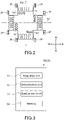
- Fig. 2 is a schematic diagram showing a road intersection to which the traffic control system 100 is applied.
- the traffic control system 100 includes a signal control device 10, a wireless base station 20, and a traffic control device 50.
- the signal control device 10 controls a plurality of signal lamps including vehicle signal lamps 1V and 2V installed on roads R1 and R2 that respectively extend in the east-west direction (in the right and left direction in the figure) and the north-source direction (in the up and down direction in the figure) and pedestrian signal lamps 1P and 2P installed on crosswalks of the respective roads.
- vehicle signal lamps 1V and 2V installed on roads R1 and R2 that respectively extend in the east-west direction (in the right and left direction in the figure) and the north-source direction (in the up and down direction in the figure) and pedestrian signal lamps 1P and 2P installed on crosswalks of the respective roads.
- the signal control device 10 controls the light emission (green, yellow, and red) of the respective signal lamps in the lighting time (phase seconds) and period on the basis of the preset signal information using a commercial power source as a power source.
- the signal control device 10 is typically installed in a control box (not shown) attached to a strut of a traffic light S, and is electrically connected to the respective lamps 1V, 2V, 1P, and 2P by wires.
- the signal control device 10 is capable of communicating with the traffic control device 50, and is configured to execute preferential signal control on a bus B running on the road R1 on the basis of a command from the traffic control device 50.
- the bus B is typically a public vehicle such as a bus including the road R1 as an operation route, and includes a regular bus and a temporary bus running on the basis of an operation diagram. Further, the bus B is not limited to these fixed-route buses, and may be a shuttle bus that reciprocates between various private or public facilities and terminals such as stations on the basis of a predetermined operation diagram. Further, the bus B may also be a self-driving vehicle.
- the bus B is equipped with a GNSS (Global Navigation Satellite System) terminal capable of acquiring GNSS information including information regarding the current position of the bus B, the current time, the running velocity, and the like from a GNSS satellite 60. Further, the bus B is equipped with an in-vehicle device Vs capable of transmitting, the wireless base station 20, vehicle information including the GNSS information described above and operation information such as an operation diagram (timetable) of the bus B, a bus name, and an in-operation/out-of-service flag.
- GNSS Global Navigation Satellite System
- the wireless base station 20 receives vehicle information transmitted from the bus B, and transmits the received vehicle information to the traffic control device 50.
- the communication line is not particularly limited. Typically, an LTE (Long Term Evolution) line is used, but it goes without saying that the communication line is not limited thereto.
- the traffic control device 50 functions as a central unit, and typically includes a computer including a CPU (Central Processing Unit) and the like.
- Fig. 3 is a block diagram showing a configuration of the traffic control device 50. As shown in Fig. 3 , the traffic control device 50 includes an acquisition unit 51, a determination unit 52, a signal generation unit 53, a memory 54, and the like.
- the acquisition unit 51 is configured to be capable of acquiring vehicle information including the GNSS information and operation information described above from the bus B via the wireless base station 20.
- the period of transmission of the vehicle information from the bus B is not particularly limited, and may be a few seconds or a few minutes.
- the acquisition unit 51 is configured to further obtain congestion information of the road R1.
- the congestion information can be obtained from, for example, a detection signal of a sensor installed on the road side of the road R1 or probe information transmitted from a vehicle capable of using a driving support system (ITS: Intelligent Transport System), and the congestion length is calculated on the basis of the occupancy of a vehicle at a predetermined position of the road R1, or the like.
- ITS Intelligent Transport System
- the determination unit 52 is configured to calculate, on the basis of the vehicle information, an estimated time of arrival at the traffic light S, and determine whether or not the estimated time is delayed from a scheduled time.
- the scheduled time refers to the time at which the vehicle is capable of arriving at a bus stop (bus station) T installed on the downstream side of the traffic light S in accordance with a timetable (or departing from the bus stop T in accordance with the timetable).
- the schedule time is not necessarily set in minutes, but may be set in several minutes.
- the estimated time at which the bus B arrives at the bus stop T can be calculated on the basis of the distance from the traffic light S to the bus stop T.
- the bus stop T is not necessarily installed on the downstream side of the traffic light S, and may be installed on the upstream side of the traffic light S.
- the signal generation unit 53 generates, where it is determined that the estimated time at which the bus B arrives at the traffic light S is delayed from a scheduled time on the basis of the operation diagram transmitted from the bus B, a control signal for causing the traffic light S to execute signal control for causing the bus B to preferentially pass therethrough.
- the determination reference of the delay may be the scheduled time itself, or may be an arbitrary time after a predetermined time has elapsed from the scheduled time.
- Typical examples of the signal control for causing the bus B to preferentially pass therethrough include increasing the time for a signal lamp light being green and decreasing the time for a signal lamp light being red.
- the memory 54 includes a storage medium such as a non-volatile semiconductor storage device and a hard disk.
- the memory 54 stores various parameters including software (programs) for causing the acquisition unit 51, the determination unit 52, and the signal generation unit 53 to operate as functional blocks, the positional information of the traffic light S and the bus stop T, and the phase step (cycle) table of the traffic light S.
- Fig. 4 is a flowchart showing an example of a processing procedure executed in the traffic control device 50.
- the acquisition unit 51 acquires, from the bus B running on the road R1 via the wireless base station 20, vehicle information (a timetable, a bus name, a current position, the current time, a running velocity, and the like) regarding the bus B in a constant period (Step 101).
- vehicle information a timetable, a bus name, a current position, the current time, a running velocity, and the like
- the acquisition unit 51 further acquires congestion information (e.g., congestion length) regarding the road R1 on which the bus B runs (Step 102).
- the determination unit 52 calculates, on the basis of the vehicle information regarding the bus B and congestion information regarding the road R1 acquired in the acquisition unit 51, an estimated time at which the bus B arrives at an intersection (the traffic light S) installed in front of the bus stop T (Step 103).
- the congestion information for calculating the estimated time of arrival it is possible to improve the accuracy for calculating the estimated time at which the bus B arrives at the traffic light S.
- the determination unit 52 may further calculate, on the basis of the vehicle information and the congestion information, an estimated time at which the bus B arrives at the bus stop T.
- the time of arrival at the bus stop T is calculated by taking into account the step cycle of the traffic light S, the distance of the line of vehicles stopping when the light color of the traffic light S is red, and the like.
- the determination unit 52 determines whether or not the estimated time at which the bus B arrives at the intersection (the traffic light S) is delayed from the scheduled time (Step 104), ends the processing as it is when delay has not occurred, and repeats the above-mentioned processing (Steps 101 to 104) again.
- the determination unit 52 determines, in the case where it is determined that the estimated time at which the bus B arrives at the intersection (the traffic light S) is delayed from the scheduled time, a light color of the traffic light S at the estimated time (Step 105).
- the light color of the traffic light S is determined on the basis of the step (cycle) table of the traffic light S.
- the signal control device 10 of the traffic light 1 is caused to execute normal signal control (Step 107).
- the signal generation unit 53 generates a control signal for causing the traffic light S to execute preferential control for causing the bus B to preferentially pass therethrough, and transmits this to the signal control device 10 (Step 108).
- the signal generation unit 53 generates a control signal for controlling the traffic light S such that the traffic light S turns a light color (i.e., green) in which the bus B is capable of passing through the traffic light S in the cycle at the estimated time at which the bus B arrives at the traffic light S.
- a control signal for extending the green lighting of the traffic light S until the estimated time in the case where the light color at the estimated time described above is yellow or shortening the red lighting in the case where the light color at the estimated time described above is red is generated.
- the preferential control for the bus B on the traffic light S by executing the preferential control for the bus B on the traffic light S, the time required for the bus B to pass through the traffic light S is shortened, and the delay of arrival at the bus stop T can be suppressed. As a result, it is possible to facilitate the operation according to the scheduled time of the bus B.
- this preferential control is realized by partially changing the step of the cycle performed the estimated time at which the bus B arrives at the traffic light S, it is possible to suppress the occurrence of traffic congestion on the road R2 crossing the road R1.
- an operation diagram of the bus B can be acquired from the vehicle information transmitted from the bus B, the operation diagram does not need to be pre-registered in the traffic control device 50, and therefore the above-mentioned preferential signal control can be applied also to a bus that is operated irregularly such as a temporary bus.
- the estimated time at which the bus B arrives at the traffic light S is calculated on the basis of the vehicle information received periodically, the estimation accuracy of the arrival time is improved, and the road situation that changes every moment can be sufficiently dealt with. Further, in accordance with this embodiment, since the estimated time at which the bus B arrives at the traffic light S is calculated by referring not only to the vehicle information of the bus B but also to the congestion information of the road R1, it is possible to further improve the accuracy of the estimated time.
- the traffic control device 50 may case a plurality of adjacent traffic lights to share signal information of the respective traffic lights and the vehicle information of the bus B. In this case, it is possible to realize the operation according to the scheduled time of the bus B by the cooperation of the plurality of traffic lights.
- the sharing of information may be performed via the traffic control device 50, or may be performed by mutual communication between traffic lights.
- Fig. 5 is a schematic configuration diagram showing a traffic control system 200 according to a second embodiment of the present invention.
- a configuration different from that of the first embodiment will be mainly described, and the same components as those of the first embodiment will be denoted by the same reference symbols, and description thereof will be omitted or simplified.
- the traffic control system 200 is different from that in the first embodiment in that it includes a signal control device 30 that controls a stand-alone traffic light S equipped with no traffic control device (central unit).
- the signal control device 30 includes the acquisition unit 51, the determination unit 52, the signal generation unit 53, and the memory 54. That is, the signal control device 30 has a function similar to that of the traffic control device 50 described in the above-mentioned first embodiment.
- the signal control device 30 is configured as part of the traffic light S installed on the road R1, and controls the signal lamp 1V installed on the road R1.
- the signal control device 30 includes, as the acquisition unit 51, a communication module capable of receiving, from the bus B, vehicle information including GNSS information and identification information of the bus B.
- the signal control device 30 is configured to be capable of acquiring the vehicle information of the bus B by the communication module described above via the wireless base station 20 (or directly without through the wireless base station 20), and executing preferential control similar to that in the above-mentioned first embodiment on the basis of the vehicle information (see Fig. 4 ).
- the above-mentioned preferential control may be executed on all traffic lights capable of receiving vehicle information.
- a bus stop at which the bus B stops next is selected and the control of the light color of each traffic light may be executed such that a plurality of traffic lights through which the bus B passes before arriving at the bus stop cooperate to cause the bus to arrive at the bus stop at the scheduled time.
- the light color control of a traffic light installed at an intersection has been described in the embodiments described above, but the present invention is also applicable to a traffic light installed at a place other than the intersection.
Landscapes
- Physics & Mathematics (AREA)
- General Physics & Mathematics (AREA)
- Chemical & Material Sciences (AREA)
- Analytical Chemistry (AREA)
- Engineering & Computer Science (AREA)
- Radar, Positioning & Navigation (AREA)
- Remote Sensing (AREA)
- Business, Economics & Management (AREA)
- Emergency Management (AREA)
- Traffic Control Systems (AREA)
Applications Claiming Priority (2)
| Application Number | Priority Date | Filing Date | Title |
|---|---|---|---|
| JP2019141533A JP7012049B2 (ja) | 2019-07-31 | 2019-07-31 | 交通管制装置及び信号機 |
| PCT/JP2020/028262 WO2021020232A1 (ja) | 2019-07-31 | 2020-07-21 | 交通管制装置及び信号機 |
Publications (4)
| Publication Number | Publication Date |
|---|---|
| EP4006868A1 true EP4006868A1 (de) | 2022-06-01 |
| EP4006868A4 EP4006868A4 (de) | 2023-08-02 |
| EP4006868B1 EP4006868B1 (de) | 2025-01-22 |
| EP4006868C0 EP4006868C0 (de) | 2025-01-22 |
Family
ID=74230303
Family Applications (1)
| Application Number | Title | Priority Date | Filing Date |
|---|---|---|---|
| EP20847607.7A Active EP4006868B1 (de) | 2019-07-31 | 2020-07-21 | Verkehrssteuerungsvorrichtung und ampel |
Country Status (5)
| Country | Link |
|---|---|
| US (1) | US11869349B2 (de) |
| EP (1) | EP4006868B1 (de) |
| JP (1) | JP7012049B2 (de) |
| CN (1) | CN114026623B (de) |
| WO (1) | WO2021020232A1 (de) |
Cited By (2)
| Publication number | Priority date | Publication date | Assignee | Title |
|---|---|---|---|---|
| EP4006868B1 (de) * | 2019-07-31 | 2025-01-22 | Koito Electric Industries, Ltd. | Verkehrssteuerungsvorrichtung und ampel |
| US12562719B2 (en) | 2023-06-13 | 2026-02-24 | Telefonaktiebolaget Lm Ericsson (Publ) | Signal pre-shaping to suppress power supply disturbances |
Families Citing this family (8)
| Publication number | Priority date | Publication date | Assignee | Title |
|---|---|---|---|---|
| CN113053142B (zh) * | 2021-02-05 | 2022-04-29 | 青岛海信网络科技股份有限公司 | 一种基于车载定位和车路协同技术的公交优先控制系统 |
| JP7501508B2 (ja) * | 2021-11-26 | 2024-06-18 | トヨタ自動車株式会社 | 道路鋲システム、道路鋲の制御方法および制御プログラム |
| CN114758516B (zh) * | 2022-04-14 | 2023-02-21 | 安徽超远信息技术有限公司 | 一种公交车优先通行的智能交通信号控制方法 |
| CN115482676B (zh) * | 2022-09-16 | 2023-08-18 | 山东交通学院 | 一种保障正点率的公交优先信号控制方法及系统 |
| JP2024058513A (ja) * | 2022-10-14 | 2024-04-25 | ソフトバンクグループ株式会社 | 自動運転車両の制御装置及びプログラム |
| US20240161611A1 (en) * | 2022-11-10 | 2024-05-16 | Janet D. Scott | Traffic Signal Control Assembly |
| JP7395050B1 (ja) | 2023-09-22 | 2023-12-08 | 章史 葛西 | 除排雪判断支援システムおよびプログラム、道路管理方法 |
| JP7857999B2 (ja) * | 2024-07-30 | 2026-05-13 | コイト電工株式会社 | 車載装置および信号制御システム |
Family Cites Families (36)
| Publication number | Priority date | Publication date | Assignee | Title |
|---|---|---|---|---|
| JPS5065197A (de) * | 1973-10-09 | 1975-06-02 | ||
| JPS5064689A (de) * | 1973-10-11 | 1975-05-31 | ||
| FR2353913A1 (fr) * | 1976-05-31 | 1977-12-30 | Sfim | Procede pour ameliorer la circulation de vehicules de transport en commun |
| JPS6065197A (ja) | 1983-09-13 | 1985-04-13 | サンロック工業株式会社 | 石膏ボ−ド用表板紙 |
| JPH05286441A (ja) * | 1992-04-10 | 1993-11-02 | Toshiba Corp | 列車ダイヤ管理装置 |
| CA2163668C (en) * | 1993-06-09 | 2005-08-16 | Jeffrey D. Haagenstad | Vehicle tracking system |
| JPH08253153A (ja) * | 1995-03-17 | 1996-10-01 | Hitachi Ltd | 列車ダイヤの合理性判定方法、列車進路制御方法および鉄道の運行管理システム |
| JPH09104347A (ja) * | 1995-10-13 | 1997-04-22 | Hitachi Ltd | 列車制御システム |
| JPH10111999A (ja) * | 1996-10-07 | 1998-04-28 | Hitachi Ltd | 路線バス検出方法、路線バス検出装置、路線バス優先制御方法及び交通管制システム |
| JP3886724B2 (ja) * | 2000-12-28 | 2007-02-28 | 株式会社構造計画研究所 | バス運行予定報知システム及び方法 |
| JP2002251697A (ja) * | 2001-02-21 | 2002-09-06 | Fujitsu Ten Ltd | バス運行管理方法および装置、車載端末装置ならびに停留所案内装置 |
| JP2004046404A (ja) * | 2002-07-10 | 2004-02-12 | Fuji Photo Film Co Ltd | 車両位置通知装置 |
| JP4357983B2 (ja) | 2004-02-17 | 2009-11-04 | パナソニック株式会社 | 遅れ時間推定装置、遅れ時間推定方法、遅れ時間推定システムおよび遅れ時間推定プログラム |
| JP2006163738A (ja) * | 2004-12-06 | 2006-06-22 | Matsushita Electric Ind Co Ltd | 運行管理装置 |
| US7432826B2 (en) | 2005-06-16 | 2008-10-07 | Global Traffic Technologies, Llc | Traffic preemption system with headway management |
| JP4743523B2 (ja) * | 2006-03-22 | 2011-08-10 | 住友電気工業株式会社 | 交差点における車両挙動の予測システム |
| JP4796559B2 (ja) * | 2007-09-21 | 2011-10-19 | 株式会社日立情報システムズ | 列車遅延自動表示システムおよび列車遅延自動表示方法ならびにそのためのプログラム |
| JP2009175235A (ja) * | 2008-01-22 | 2009-08-06 | Harison Toshiba Lighting Corp | 液晶表示装置の点灯システム |
| JP5104344B2 (ja) | 2008-01-28 | 2012-12-19 | 住友電気工業株式会社 | 交通信号制御装置、コンピュータプログラム及び交通信号制御方法 |
| JP2010250646A (ja) * | 2009-04-17 | 2010-11-04 | Sumitomo Electric Ind Ltd | 公共車両優先信号制御システム及び公共車両優先信号制御方法 |
| JP5526788B2 (ja) | 2010-01-05 | 2014-06-18 | 住友電気工業株式会社 | 交通信号制御システム、交通信号制御機、中央装置及びプログラム |
| JP5492608B2 (ja) * | 2010-03-09 | 2014-05-14 | 株式会社ナビタイムジャパン | ナビゲーションシステム、ナビゲーションサーバ、ナビゲーション方法、および、プログラム |
| JP2012103843A (ja) | 2010-11-09 | 2012-05-31 | Sumitomo Electric Ind Ltd | 信号制御装置及び信号制御方法 |
| WO2013003504A2 (en) * | 2011-06-27 | 2013-01-03 | Stc, Inc. | Signal light priority system utilizing estimated time of arrival |
| CN202584431U (zh) | 2011-12-23 | 2012-12-05 | 北京易华录信息技术股份有限公司 | 一种基于时刻表的公交优先控制系统 |
| CN102568221A (zh) | 2011-12-23 | 2012-07-11 | 北京易华录信息技术股份有限公司 | 一种基于时刻表的公交优先控制系统及其方法 |
| JP2015039994A (ja) * | 2013-08-23 | 2015-03-02 | 株式会社日立製作所 | 列車運行指令装置および列車運行管理システム |
| US10320923B2 (en) * | 2016-09-01 | 2019-06-11 | Cisco Technology, Inc. | Predictive resource preparation and handoff for vehicle-to-infrastructure systems |
| CN108230702A (zh) * | 2016-12-13 | 2018-06-29 | 上海宝康电子控制工程有限公司 | 在线有轨电车优先策略控制系统及其方法 |
| CH714419B1 (de) | 2017-12-11 | 2021-11-15 | Graphmasters Sa C/O Robert Dohrendorf | System und Verfahren zum Verringern von Wartezeiten im Strassenverkehr. |
| CN108010348B (zh) * | 2017-12-27 | 2021-08-17 | 中车株洲电力机车研究所有限公司 | 一种智轨列车的路口信号优先系统及方法 |
| CN108470455B (zh) | 2018-03-21 | 2021-09-24 | 千寻位置网络(浙江)有限公司 | 一种公交优先系统及控制方法 |
| CN108898824B (zh) * | 2018-07-25 | 2021-06-29 | 公安部交通管理科学研究所 | 一种基于c-v2x的交叉口公交信号优先控制系统及控制方法 |
| CN109552364A (zh) * | 2018-11-19 | 2019-04-02 | 东莞理工学院 | 一种基于大数据的轨道交通调度预警系统 |
| US10720053B1 (en) * | 2019-03-05 | 2020-07-21 | Siemens Mobility, Inc. | Busway crossing warning system and method for controlling busway crossing traffic |
| JP7012049B2 (ja) * | 2019-07-31 | 2022-01-27 | コイト電工株式会社 | 交通管制装置及び信号機 |
-
2019
- 2019-07-31 JP JP2019141533A patent/JP7012049B2/ja active Active
-
2020
- 2020-07-21 CN CN202080045762.7A patent/CN114026623B/zh active Active
- 2020-07-21 WO PCT/JP2020/028262 patent/WO2021020232A1/ja not_active Ceased
- 2020-07-21 EP EP20847607.7A patent/EP4006868B1/de active Active
- 2020-07-21 US US17/595,969 patent/US11869349B2/en active Active
Cited By (2)
| Publication number | Priority date | Publication date | Assignee | Title |
|---|---|---|---|---|
| EP4006868B1 (de) * | 2019-07-31 | 2025-01-22 | Koito Electric Industries, Ltd. | Verkehrssteuerungsvorrichtung und ampel |
| US12562719B2 (en) | 2023-06-13 | 2026-02-24 | Telefonaktiebolaget Lm Ericsson (Publ) | Signal pre-shaping to suppress power supply disturbances |
Also Published As
| Publication number | Publication date |
|---|---|
| EP4006868B1 (de) | 2025-01-22 |
| US11869349B2 (en) | 2024-01-09 |
| WO2021020232A1 (ja) | 2021-02-04 |
| JP7012049B2 (ja) | 2022-01-27 |
| CN114026623A (zh) | 2022-02-08 |
| EP4006868A4 (de) | 2023-08-02 |
| CN114026623B (zh) | 2023-11-07 |
| US20220319315A1 (en) | 2022-10-06 |
| JP2021026322A (ja) | 2021-02-22 |
| EP4006868C0 (de) | 2025-01-22 |
Similar Documents
| Publication | Publication Date | Title |
|---|---|---|
| EP4006868B1 (de) | Verkehrssteuerungsvorrichtung und ampel | |
| CN105869415B (zh) | 车路协同交通灯及车路协同交通灯的控制方法 | |
| US11270580B2 (en) | Traffic signal control apparatus, traffic signal control method, and computer program | |
| US20200312133A1 (en) | Express Lane Planning Method and Unit | |
| US10752244B2 (en) | Devices, method and computer program for providing information about an expected driving intention | |
| JP6421580B2 (ja) | 交通信号制御装置、コンピュータプログラム、及び交通信号制御方法 | |
| CN102473349B (zh) | 交通信号控制系统、交通信号控制设备和交通信号控制方法 | |
| US9805597B2 (en) | Method and device for communication between road users and/or pedestrians and a traffic infrastructure on the basis of an ad-hoc wireless motor vehicle communications system for traffic control | |
| US9805593B2 (en) | Method for communication within an, in particular wireless, motor vehicle communication system interacting in an ad-hoc manner, device for the traffic infrastructure and road user device | |
| US20150029039A1 (en) | Driving support device | |
| US20200402397A1 (en) | Traffic signal control apparatus, traffic signal control method, and computer program | |
| KR101243862B1 (ko) | 유티아이에스를 이용한 버스우선신호 시스템 | |
| US10916133B2 (en) | Determination of an optimum speed for a motor vehicle approaching a traffic light | |
| CN110546695A (zh) | 用于交通灯的信号相位和定时的综合管理的方法、装置和计算机程序产品 | |
| US20130135117A1 (en) | Roadside-to-vehicle communication system and driving support system | |
| US10482763B1 (en) | Network-based vehicle traffic signal control system | |
| JP2016115247A (ja) | 交通信号制御装置、コンピュータプログラム、及び交通信号制御方法 | |
| KR20160049691A (ko) | 교통정보 제공 장치 및 방법 | |
| CN110999336A (zh) | 选择性使用不同类型的网络获取关于一个或多个交通信号和路口的信息的方法和装置 | |
| CN116057605A (zh) | 车载装置、信息分发装置、驾驶辅助系统、控制方法及计算机程序 | |
| US20150112590A1 (en) | Method for Communicating within an Ad Hoc-Type Motor Vehicle Communication System | |
| JP2017112832A (ja) | 列車制御システム | |
| US12260752B2 (en) | Communication system, server apparatus, program and communication method | |
| JP7432010B2 (ja) | 無線路側機、交通通信システム、及び交通通信方法 | |
| US20140370801A1 (en) | Method and apparatus for a device to control transmissions of safety messages from other vehicles |
Legal Events
| Date | Code | Title | Description |
|---|---|---|---|
| STAA | Information on the status of an ep patent application or granted ep patent |
Free format text: STATUS: THE INTERNATIONAL PUBLICATION HAS BEEN MADE |
|
| PUAI | Public reference made under article 153(3) epc to a published international application that has entered the european phase |
Free format text: ORIGINAL CODE: 0009012 |
|
| STAA | Information on the status of an ep patent application or granted ep patent |
Free format text: STATUS: REQUEST FOR EXAMINATION WAS MADE |
|
| 17P | Request for examination filed |
Effective date: 20211216 |
|
| AK | Designated contracting states |
Kind code of ref document: A1 Designated state(s): AL AT BE BG CH CY CZ DE DK EE ES FI FR GB GR HR HU IE IS IT LI LT LU LV MC MK MT NL NO PL PT RO RS SE SI SK SM TR |
|
| DAV | Request for validation of the european patent (deleted) | ||
| DAX | Request for extension of the european patent (deleted) | ||
| A4 | Supplementary search report drawn up and despatched |
Effective date: 20230705 |
|
| RIC1 | Information provided on ipc code assigned before grant |
Ipc: G08G 1/01 20060101ALI20230629BHEP Ipc: G08G 1/087 20060101ALI20230629BHEP Ipc: G08G 1/127 20060101ALI20230629BHEP Ipc: G08G 1/07 20060101AFI20230629BHEP |
|
| STAA | Information on the status of an ep patent application or granted ep patent |
Free format text: STATUS: EXAMINATION IS IN PROGRESS |
|
| 17Q | First examination report despatched |
Effective date: 20231019 |
|
| GRAP | Despatch of communication of intention to grant a patent |
Free format text: ORIGINAL CODE: EPIDOSNIGR1 |
|
| STAA | Information on the status of an ep patent application or granted ep patent |
Free format text: STATUS: GRANT OF PATENT IS INTENDED |
|
| INTG | Intention to grant announced |
Effective date: 20240820 |
|
| GRAS | Grant fee paid |
Free format text: ORIGINAL CODE: EPIDOSNIGR3 |
|
| GRAA | (expected) grant |
Free format text: ORIGINAL CODE: 0009210 |
|
| STAA | Information on the status of an ep patent application or granted ep patent |
Free format text: STATUS: THE PATENT HAS BEEN GRANTED |
|
| AK | Designated contracting states |
Kind code of ref document: B1 Designated state(s): AL AT BE BG CH CY CZ DE DK EE ES FI FR GB GR HR HU IE IS IT LI LT LU LV MC MK MT NL NO PL PT RO RS SE SI SK SM TR |
|
| REG | Reference to a national code |
Ref country code: GB Ref legal event code: FG4D |
|
| REG | Reference to a national code |
Ref country code: CH Ref legal event code: EP |
|
| REG | Reference to a national code |
Ref country code: IE Ref legal event code: FG4D |
|
| REG | Reference to a national code |
Ref country code: DE Ref legal event code: R096 Ref document number: 602020045279 Country of ref document: DE |
|
| U01 | Request for unitary effect filed |
Effective date: 20250214 |
|
| U07 | Unitary effect registered |
Designated state(s): AT BE BG DE DK EE FI FR IT LT LU LV MT NL PT RO SE SI Effective date: 20250224 |
|
| PG25 | Lapsed in a contracting state [announced via postgrant information from national office to epo] |
Ref country code: RS Free format text: LAPSE BECAUSE OF FAILURE TO SUBMIT A TRANSLATION OF THE DESCRIPTION OR TO PAY THE FEE WITHIN THE PRESCRIBED TIME-LIMIT Effective date: 20250422 |
|
| PG25 | Lapsed in a contracting state [announced via postgrant information from national office to epo] |
Ref country code: PL Free format text: LAPSE BECAUSE OF FAILURE TO SUBMIT A TRANSLATION OF THE DESCRIPTION OR TO PAY THE FEE WITHIN THE PRESCRIBED TIME-LIMIT Effective date: 20250122 |
|
| PG25 | Lapsed in a contracting state [announced via postgrant information from national office to epo] |
Ref country code: ES Free format text: LAPSE BECAUSE OF FAILURE TO SUBMIT A TRANSLATION OF THE DESCRIPTION OR TO PAY THE FEE WITHIN THE PRESCRIBED TIME-LIMIT Effective date: 20250122 |
|
| PG25 | Lapsed in a contracting state [announced via postgrant information from national office to epo] |
Ref country code: IS Free format text: LAPSE BECAUSE OF FAILURE TO SUBMIT A TRANSLATION OF THE DESCRIPTION OR TO PAY THE FEE WITHIN THE PRESCRIBED TIME-LIMIT Effective date: 20250522 Ref country code: NO Free format text: LAPSE BECAUSE OF FAILURE TO SUBMIT A TRANSLATION OF THE DESCRIPTION OR TO PAY THE FEE WITHIN THE PRESCRIBED TIME-LIMIT Effective date: 20250422 |
|
| PG25 | Lapsed in a contracting state [announced via postgrant information from national office to epo] |
Ref country code: HR Free format text: LAPSE BECAUSE OF FAILURE TO SUBMIT A TRANSLATION OF THE DESCRIPTION OR TO PAY THE FEE WITHIN THE PRESCRIBED TIME-LIMIT Effective date: 20250122 |
|
| PG25 | Lapsed in a contracting state [announced via postgrant information from national office to epo] |
Ref country code: GR Free format text: LAPSE BECAUSE OF FAILURE TO SUBMIT A TRANSLATION OF THE DESCRIPTION OR TO PAY THE FEE WITHIN THE PRESCRIBED TIME-LIMIT Effective date: 20250423 |
|
| U20 | Renewal fee for the european patent with unitary effect paid |
Year of fee payment: 6 Effective date: 20250710 |
|
| PG25 | Lapsed in a contracting state [announced via postgrant information from national office to epo] |
Ref country code: SM Free format text: LAPSE BECAUSE OF FAILURE TO SUBMIT A TRANSLATION OF THE DESCRIPTION OR TO PAY THE FEE WITHIN THE PRESCRIBED TIME-LIMIT Effective date: 20250122 |
|
| PGFP | Annual fee paid to national office [announced via postgrant information from national office to epo] |
Ref country code: GB Payment date: 20250722 Year of fee payment: 6 |
|
| PG25 | Lapsed in a contracting state [announced via postgrant information from national office to epo] |
Ref country code: CZ Free format text: LAPSE BECAUSE OF FAILURE TO SUBMIT A TRANSLATION OF THE DESCRIPTION OR TO PAY THE FEE WITHIN THE PRESCRIBED TIME-LIMIT Effective date: 20250122 |
|
| PG25 | Lapsed in a contracting state [announced via postgrant information from national office to epo] |
Ref country code: SK Free format text: LAPSE BECAUSE OF FAILURE TO SUBMIT A TRANSLATION OF THE DESCRIPTION OR TO PAY THE FEE WITHIN THE PRESCRIBED TIME-LIMIT Effective date: 20250122 |
|
| PLBE | No opposition filed within time limit |
Free format text: ORIGINAL CODE: 0009261 |
|
| STAA | Information on the status of an ep patent application or granted ep patent |
Free format text: STATUS: NO OPPOSITION FILED WITHIN TIME LIMIT |
|
| REG | Reference to a national code |
Ref country code: CH Ref legal event code: L10 Free format text: ST27 STATUS EVENT CODE: U-0-0-L10-L00 (AS PROVIDED BY THE NATIONAL OFFICE) Effective date: 20251203 |
|
| 26N | No opposition filed |
Effective date: 20251023 |
|
| REG | Reference to a national code |
Ref country code: CH Ref legal event code: H13 Free format text: ST27 STATUS EVENT CODE: U-0-0-H10-H13 (AS PROVIDED BY THE NATIONAL OFFICE) Effective date: 20260224 |
|
| PG25 | Lapsed in a contracting state [announced via postgrant information from national office to epo] |
Ref country code: CH Free format text: LAPSE BECAUSE OF NON-PAYMENT OF DUE FEES Effective date: 20250731 |
|
| PG25 | Lapsed in a contracting state [announced via postgrant information from national office to epo] |
Ref country code: IE Free format text: LAPSE BECAUSE OF NON-PAYMENT OF DUE FEES Effective date: 20250721 |
|
| PG25 | Lapsed in a contracting state [announced via postgrant information from national office to epo] |
Ref country code: MC Free format text: LAPSE BECAUSE OF FAILURE TO SUBMIT A TRANSLATION OF THE DESCRIPTION OR TO PAY THE FEE WITHIN THE PRESCRIBED TIME-LIMIT Effective date: 20250122 |
|
| PG25 | Lapsed in a contracting state [announced via postgrant information from national office to epo] |
Ref country code: CY Free format text: LAPSE BECAUSE OF FAILURE TO SUBMIT A TRANSLATION OF THE DESCRIPTION OR TO PAY THE FEE WITHIN THE PRESCRIBED TIME-LIMIT Effective date: 20250122 |