EP4006940A1 - Commutateur - Google Patents
Commutateur Download PDFInfo
- Publication number
- EP4006940A1 EP4006940A1 EP19939172.3A EP19939172A EP4006940A1 EP 4006940 A1 EP4006940 A1 EP 4006940A1 EP 19939172 A EP19939172 A EP 19939172A EP 4006940 A1 EP4006940 A1 EP 4006940A1
- Authority
- EP
- European Patent Office
- Prior art keywords
- movable
- electrode
- movable shaft
- mover
- stationary
- Prior art date
- Legal status (The legal status is an assumption and is not a legal conclusion. Google has not performed a legal analysis and makes no representation as to the accuracy of the status listed.)
- Granted
Links
Images


Classifications
-
- H—ELECTRICITY
- H01—ELECTRIC ELEMENTS
- H01H—ELECTRIC SWITCHES; RELAYS; SELECTORS; EMERGENCY PROTECTIVE DEVICES
- H01H33/00—High-tension or heavy-current switches with arc-extinguishing or arc-preventing means
- H01H33/60—Switches wherein the means for extinguishing or preventing the arc do not include separate means for obtaining or increasing flow of arc-extinguishing fluid
- H01H33/66—Vacuum switches
- H01H33/664—Contacts; Arc-extinguishing means, e.g. arcing rings
-
- H—ELECTRICITY
- H01—ELECTRIC ELEMENTS
- H01H—ELECTRIC SWITCHES; RELAYS; SELECTORS; EMERGENCY PROTECTIVE DEVICES
- H01H33/00—High-tension or heavy-current switches with arc-extinguishing or arc-preventing means
- H01H33/02—Details
- H01H33/42—Driving mechanisms
-
- H—ELECTRICITY
- H01—ELECTRIC ELEMENTS
- H01H—ELECTRIC SWITCHES; RELAYS; SELECTORS; EMERGENCY PROTECTIVE DEVICES
- H01H33/00—High-tension or heavy-current switches with arc-extinguishing or arc-preventing means
- H01H33/60—Switches wherein the means for extinguishing or preventing the arc do not include separate means for obtaining or increasing flow of arc-extinguishing fluid
- H01H33/66—Vacuum switches
- H01H33/666—Operating arrangements
- H01H33/6662—Operating arrangements using bistable electromagnetic actuators, e.g. linear polarised electromagnetic actuators
Definitions
- the present invention relates to a switch that performs opening and closing of electrodes in a circuit.
- Some switch including a stationary electrode and a movable electrode is provided with a contact pressure spring that applies contact pressure to the stationary electrode and the movable electrode.
- the contact pressure spring in a contracted state presses the movable electrode against the stationary electrode, thus applying the contact pressure to the stationary electrode and the movable electrode.
- the contact pressure spring is restored from the contracted state, so that the contact pressure becomes zero. After the contact pressure becomes zero, the movable electrode starts to separate from the stationary electrode.
- Patent Literature 1 discloses a switch that includes a contact pressure spring between two movable shafts.
- One of the two movable shafts is a first movable shaft connected to a movable core of a handler.
- Another of the two movable shafts is a second movable shaft connected to a movable electrode.
- the first movable shaft is provided with, at an end opposite from an end connected to the movable core, a housing that houses the contact pressure spring.
- the second movable shaft is provided with a flange at an end opposite from an end connected to the movable electrode. The flange is connected to one end of the contact pressure spring inside the housing.
- the contact pressure spring is connected to an internal wall face of the housing at another end.
- Patent Literature 1 PCT International Publication No. 2016/181732
- the contact pressure spring could cause a moving speed differential between the first movable shaft and the second movable shaft.
- the handler starts decelerating the movable core, with the movable electrode at a certain distance from the stationary electrode during withdrawal of the movable electrode, the first movable shaft is decelerated along with the movable core.
- the contact pressure spring contracts under inertial force from the second movable shaft, so that the second movable shaft, on the other hand, does not decelerate but continues moving at the same speed as before the movable core starts decelerating.
- the present invention has been made in view of the above, and an object of the present invention is to obtain a switch that enables speed of a movable electrode to be controlled in accordance with a speed adjustment that is made by a handler.
- a switch includes: a pair of electrodes that serve as a stationary electrode and a movable electrode; a handler including a first mover that operates in withdrawing the movable electrode from the stationary electrode and closing the movable electrode toward the stationary electrode; a second mover connected to the movable electrode; an elastic that is connected between the first mover and the second mover to press the movable electrode against the stationary electrode; and an attenuator that attenuates contraction of the elastic when the movable electrode is withdrawn from the stationary electrode.
- the switch according to the present invention enables speed of the movable electrode to be controlled in accordance with a speed adjustment that is made by the handler.
- FIG. 1 illustrates a switch according to the first embodiment of the present invention, namely, a vacuum circuit breaker.
- the vacuum circuit breaker 100 which is the switch according to the first embodiment, opening and closing of a pair of electrodes serving as a stationary electrode 2 and a movable electrode 3 are performed inside a vacuum valve 1 having a higher vacuum.
- the vacuum valve 1 is a hollow body that is cylindrical.
- the stationary electrode 2 is fixed inside the vacuum valve 1.
- the movable electrode 3 is movable with respect to the stationary electrode 2.
- the vacuum circuit breaker 100 may be said to be in a closed state when the stationary electrode 2 and the movable electrode 3 are electrically connected, and the vacuum circuit breaker 100 may be said to be in an open state when the conduction between the stationary electrode 2 and the movable electrode 3 is interrupted.
- FIG. 1 A top part of FIG. 1 illustrates the vacuum circuit breaker 100 in the closed state.
- a bottom part of FIG. 1 illustrates the vacuum circuit breaker 100 in the open state.
- constituent elements of the vacuum circuit breaker 100 include constituent elements shown in section and constituent elements shown in plan view. Some sections have no hatching.
- the vacuum circuit breaker 100 includes a handler 4 that operates to withdraw the movable electrode 3 from the stationary electrode 2 and close the movable electrode 3 toward the stationary electrode 2.
- the term “withdraw” refers to separating the movable electrode 3, in contact with the stationary electrode 2, from the stationary electrode 2.
- the term “close” refers to drawing the movable electrode 3 that is away from the stationary electrode 2 to the stationary electrode 2 and establishing contact between the movable electrode 3 and the stationary electrode 2.
- the handler 4 includes a cylindrical case 15.
- a columnar stationary core 6 and a cylindrical movable core 7 are housed in the case 15.
- the stationary core 6 and the movable core 7 are arranged coaxially with each other.
- the stationary core 6 is fixed inside the case 15.
- the movable core 7 is movable inside the case 15 with respect to the stationary core 6.
- the movable core 7 is capable of axial reciprocation.
- a permanent magnet 12 is provided at a portion of the stationary core 6 to make contact with the movable core 7 in the closed state.
- the handler 4 includes a plurality of drive coils 13 for driving the movable core 7.
- the plurality of drive coils 13 include a withdrawal drive coil 13 and a closing drive coil 13.
- Each of the drive coils 13 is surrounded by the stationary core 6 and is wound about the axis of the stationary core 6.
- Each drive coil 13 generates magnetic flux that passes through the stationary core 6 and the movable core 7.
- the handler 4 is provided with a drive circuit that causes electric current pass through each of the plurality of drive coils 13. The drive circuit is not illustrated in FIG. 1 .
- a movable shaft 16 is provided at one of axial ends of the movable core 7 that is opposite from another axial end facing the stationary core 6.
- the movable shaft 16 passes through a hole formed in the case 15, extending out of the case 15.
- a spring bearing 17 is provided at a portion outside the case 15 of the movable shaft 16.
- a coil spring 11 is provided as an elastic between the case 15 and the spring bearing 17.
- the coil spring 11 is connected at one end to an external wall face of the case 15.
- the coil spring bearing 11 is connected at another end to the spring bearing 17.
- the movable shaft 16 passes through an interior of the coil spring 11.
- the movable shaft 16 is connected to a decelerator 5 at an end opposite from the movable core 7.
- the decelerator 5 decelerates the movable core 7 during the withdrawal of the movable electrode 3.
- a dashpot is usable as the decelerator 5.
- a movable shaft 18 is provided at the axial end of the movable core 7 that faces the stationary core 6.
- the movable shaft 18 passes through the stationary core 6, extending out of the case 15.
- the movable shaft 18 is connected at one end to the movable core 7.
- a hollow housing 19 is provided at another end of the movable shaft 18.
- a coil spring 14 is housed as an elastic in the housing 19.
- the coil spring 14 is a contact pressure spring that presses the movable electrode 3 against the stationary electrode 2.
- the movable shaft 18 and the housing 19 are constituent elements that move integrally with the movable core 7 and are regarded as a part of the handler 4.
- the movable shaft 18 and the housing 19 function as a first mover that operates in withdrawing and closing the movable electrode 3.
- the configuration of the handler 4 in the first embodiment is an example.
- the configuration of the handler 4 may be appropriately altered.
- the housing 19 includes an opening 24 in an end closer to the vacuum valve 1, and a movable shaft 21 passes through the opening 24.
- the movable shaft 21 is a second mover connected to the movable electrode 3.
- the movable shaft 21 extends out of the housing 19 through the opening 24.
- Inside the vacuum valve 1, the movable shaft 21 is connected to the movable electrode 3 and extends out of the vacuum valve 1.
- the movable shaft 21 is axially movable while maintaining the vacuum in the vacuum valve 1.
- the movable electrode 3 is connected to one end of the movable shaft 21.
- An insulating rod that insulates the movable shaft 21 and the movable electrode 3 from each other is provided between the movable shaft 21 and the movable electrode 3. Illustration of the insulating rod is omitted in FIG. 1 .
- a flange 20 is provided at another end of the movable shaft 21.
- the flange 20 is arranged inside the housing 19.
- An outside diameter of the flange 20 is greater than an inside diameter of the opening 24.
- the flange 20 In the closed state of the vacuum circuit breaker 100, the flange 20 is positioned away from an internal wall face 22 of the end of the housing 19 that is closer to the vacuum valve 1. In the open state of the vacuum circuit breaker 100, the flange 20 is in contact with the internal wall face 22.
- the coil spring 14 is connected at one end to the flange 20.
- the coil spring 14 is connected at another end to an internal wall face of the housing 19 that is closer to the handler 4.
- the coil spring 14 is connected between the first mover and the second mover.
- An elastic other than the coil spring 14 may be connected between the first mover and the second mover.
- Such an elastic may be a spring other than the coil spring 14, such as a disk spring or a flat spring.
- the elastic in the vacuum circuit breaker 100 may be an elastic other than the spring.
- the handler 4 is provided with a shock absorber 8.
- the shock absorber 8 is an attenuator that attenuates contraction of the coil spring 14 when the movable electrode 3 is withdrawn from the stationary electrode 2.
- the shock absorber 8 displaces the end 23 toward the handler 4.
- the shock absorber 8 generates resisting force against the force applied to the end 23, thus decelerating moving speed of the moving end 23.
- the movable shaft 21 is provided with a flat plate 9 at a portion between the vacuum valve 1 and the housing 19.
- the movable shaft 21 passes through the flat plate 9.
- the flat plate 9 is fixed to the movable shaft 21.
- the flat plate 9 moves integrally with the movable shaft 21.
- the end 23 and the flat plate 9 face each other.
- the end 23 is in contact with the flat plate 9.
- Position P1 denotes a position of the movable core 7 in the closed state.
- Position P2 denotes a position of the movable electrode 3 in the closed state.
- Position P3 denotes a position of the movable core 7 in the open state.
- Position P4 denotes a position of the movable electrode 3 in the open state.
- the movable core 7 shifts from position P1 to position P3; and the movable electrode 3 shifts from position P2 to position P4.
- the movable electrode 3 is being closed toward the stationary electrode 2: the movable core 7 shifts from position P3 to position P1; and the movable electrode 3 shifts from position P4 to position P2.
- the movable core 7 may be said to be shifting in an opening direction when the movable electrode 3 is being withdrawn, and the movable core 7 may be said to be shifting in a closing direction when the movable electrode 3 is being closed. The closing direction is opposite to the opening direction.
- the movable core 7 is attracted to the permanent magnet 12 by magnetic force of the permanent magnet 12; with the movable core 7 being attracted to the permanent magnet 12, the end of the movable core 7 that is closer to the stationary core 6 is in contact with the stationary core 6; the movable shaft 18 is at a position that is closest to the vacuum valve 1 in an axial moving range of the movable shaft 18; the flat plate 9 is sandwiched between the housing 19 and an external wall face of the vacuum valve 1; the coil spring 14 is contracted between the internal wall face of the housing 19 and the flange 20; and the movable shaft 21 presses the movable electrode 3 against the stationary electrode 2 due to reaction force of the coil spring 14.
- the handler 4 When the vacuum circuit breaker 100 is in the closed state, the handler 4 causes electric current to flow through the withdrawal drive coil 13 in response to a withdrawal operation command input to the handler 4.
- the operation command is input to the handler 4 from a control panel that controls the vacuum circuit breaker 100.
- the control panel is not illustrated in FIG. 1 .
- the withdrawal drive coil 13 With the current flowing through the withdrawal drive coil 13, the withdrawal drive coil 13 generates electromagnetic force that can counteract the magnetic force of the permanent magnet 12.
- the magnetic force of the permanent magnet 12 weakens by being counteracted by the generated electromagnetic force of the withdrawal drive coil 13.
- the reaction force of the coil spring 11 becomes greater than the force that causes the movable core 7 to be attracted to the permanent magnet 12 due to the weakened magnetic force of the permanent magnet 12, the coil spring 11 is restored from the contracted state to a state of its equilibrium length, shifting the spring bearing 17 in the opening direction.
- the movable shaft 16 and the movable core 7 move in the opening direction along with the spring bearing 17. This is how the movable core 7 of the vacuum circuit breaker 100 is moved in the opening direction.
- the movable shaft 18 and the housing 19 move in the opening direction along with the movable core 7.
- the movement of the housing 19 in the opening direction gradually decreases a distance between the flange 20 and the internal wall face 22 and causes the coil spring 14 to stretch.
- the stretching of coil spring 14 lessens contact pressure between the stationary electrode 2 and the movable electrode 3.
- the movable shaft 18 and the housing 19 move further in the opening direction after the flange 20 contacts the internal wall face 22; accordingly, the movable shaft 21 moves in the opening direction along with the movable shaft 18 and the housing 19.
- the movable electrode 3 is withdrawn from the stationary electrode 2. This is how the vacuum circuit breaker 100 transitions from the closed state to the open state.
- the flat plate 9 moves in the opening direction along with the movable shaft 21 and reaches the end 23.
- the flat plate 9 applies the force to the end 23 in the opening direction.
- the shock absorber 8 generates the resisting force against the force applied to the end 23.
- the shock absorber 8 absorbs kinetic energy of the movable shaft 21 by generating the resisting force, thus easing the movable shaft 21. A detailed description of the function of the shock absorber 8 will be provided later.
- the handler 4 causes the electric to flow through the closing drive coil 13 in response to a closing operation command input to the handler 4; with the electric current flowing through the closing drive coil 13, the closing drive coil 13 generates electromagnetic force that attracts the movable core 7; and due to the generated electromagnetic force of the closing drive coil 13 and the magnetic force of the permanent magnet 12, the movable core 7 moves in the closing direction while causing the coil spring 11 to contract.
- the movable core 7 moves in the closing direction
- the movable shaft 18 and the housing 19 move in the closing direction along with the movable core 7.
- the movable shaft 21 moves in the closing direction along with the housing 19, thus causing the movable electrode 3 to reach the stationary electrode 2.
- the coil spring 14 in the housing 19 is contracted and thus applies the contact pressure to the stationary electrode 2 and the movable electrode 3. This is how the vacuum circuit breaker 100 transitions from the open state to the closed state.
- the function of the shock absorber 8 is described here.
- the decelerator 5 starts to decelerate the movable core 7 after the movable electrode 3 is separated from the stationary electrode 2 in the withdrawal of the movable electrode 3.
- the movable shaft 18 and the housing 19 start to decelerate along with the movable core 7, because the movable shaft 18 and the housing 19 are integral with the movable core 7.
- the housing 19 starts decelerating, inertial force caused by the movement of the movable shaft 21 in the opening direction is applied on the coil spring 14.
- the shock absorber 8 attenuates the contraction of the coil spring 14 in the first embodiment, thus decelerating the movable shaft 21.
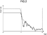
- FIG. 2 is used for explaining the function of the shock absorber, which serves as the attenuator of the vacuum circuit breaker illustrated in FIG. 1 .
- FIG. 2 illustrates a waveform representing a relationship between position of the movable shaft 18 and time, and a waveform representing a relationship between position of the movable shaft 21 and the time.
- the waveform representing the relationship between the position of each of the movable shafts 18 and 21 and the time may hereinafter be referred to as "travel waveform" in a description below.
- a broken line graph in FIG. 2 exemplifies the travel waveform of the movable shaft 18 in the withdrawal of the movable electrode 3.
- a solid line graph exemplifies the travel waveform of the movable shaft 21 in the withdrawal of the movable electrode 3.
- the travel waveforms illustrated in FIG. 2 indicate a case when the decelerator 5 decelerates the movable core 7 after the separation of the movable electrode 3 from the stationary electrode 2, and no deceleration of the movable shaft 21 is performed by the shock absorber 8.
- FIG. 2 A vertical axis of the graphs illustrated in FIG. 2 represents the position, and a horizontal axis represents the time.
- FIG. 2 has a position on the vertical axis that denotes a position of the movable shaft 18 in the open state aligned with a position on the vertical axis that denotes a position of the movable shaft 21 in the open state.
- the vacuum circuit breaker 100 is in the closed state.
- the movable shaft 18 and the movable shaft 21 remain in constant positions, respectively.
- a distance between the graph for the movable shaft 18 and the graph for the movable shaft 21 along the vertical axis represents a length of the coil spring 14 contracted from the equilibrium length.
- the movable core 7 is at position P1.
- the movable electrode 3 is at position P2.
- the vacuum circuit breaker 100 starts the withdrawal in accordance with the operation command.
- the movable electrode 3 starts to shift in the opening direction from position P2.
- the movable electrode 3 separates from the stationary electrode 2.
- the decelerator 5 starts to decelerate the movable core 7 after time t1
- the movable shaft 18 is decelerated along with the movable core 7.
- the movable shaft 21 lags behind the movable shaft 18 in starting the deceleration because the coil spring 14 contracts.
- the vacuum circuit breaker 100 is in the open state.
- the movable core 7 is at position P3.
- the movable electrode 3 is at position P4.
- the shock absorber 8 when the flat plate 9 reaches the end 23 during the movement of the movable shaft 21 in the opening direction, the shock absorber 8 generates the resisting force against the force that is applied in the opening direction by the flat plate 9, thus easing the movement of the flat plate 9 in the opening direction.
- the shock absorber 8 suppresses the contraction of the coil spring 14 during the deceleration of the movable shaft 18. This is how the shock absorber 8 attenuates the contraction of the coil spring 14 after the decelerator 5 has started decelerating the movable core 7.
- the vacuum circuit breaker 100 enables the deceleration of the movable shaft 21 to concur with the deceleration of the movable shaft 18. Since the deceleration of the movable shaft 21 is caused to concur with the deceleration of the movable shaft 18, the vacuum circuit breaker 100 enables the speed adjustment that is made by the handler 4 to be accurately reflected in speed of the movable electrode 3. The travel waveform of the movable shaft 21 approximates the travel waveform of the movable shaft 18.
- a longitudinal magnetic field may be generated between the stationary electrode 2 and the movable electrode 3.
- the longitudinal magnetic field generated causes an arc that occurs between the stationary electrode 2 and the movable electrode 3 during interruption to extend over entire electrode faces, so that electric current density by the arc discharge lowers. With the lower electric current density, melting of the stationary electrode 2 and the movable electrode 3 is suppressed. Since vapor that results from the melting is suppressed, easy current interruption is possible in the vacuum circuit breaker 100.
- the vacuum circuit breaker 100 may be provided with electrodes that generate the longitudinal magnetic field. The electrodes that generate the longitudinal magnetic field are not illustrated in FIG. 1 .
- Decelerating the movable electrode 3 during the withdrawal of the movable electrode 3 from the stationary electrode 2 enables improved interruption performance of the longitudinal magnetic field in the vacuum circuit breaker 100.
- the vacuum circuit breaker 100 enables the movable electrode 3 to decelerate in accordance with the speed adjustment that is made by the handler 4. Since the movable electrode 3 is decelerated in accordance with the speed adjustment that is made by the handler 4, the vacuum circuit breaker 100 is capable of achieving a higher interruption performance.
- the attenuator of the vacuum circuit breaker 100 may be a mechanism other than the shock absorber 8 as far as the mechanism: generates resisting force against the force applied on the elastic in conjunction with the movement of the movable shaft 21; and attenuates the contraction of the elastic.
- the attenuator may be a mechanism such as a dashpot or a mechanical linkage.
- the switch according to the first embodiment may be a circuit breaker other than the vacuum circuit breaker 100 or a disconnector.
- the switch according to the first embodiment includes the attenuator that attenuates the contraction of the elastic when the movable electrode 3 is withdrawn from the stationary electrode 2 and thus enables the movable electrode 3 to decelerate in accordance with the speed adjustment that is made by the handler 4. Therefore, the switch enables the speed of the movable electrode 3 to be controlled in accordance with the speed adjustment that is made by the handler 4.
- FIG. 3 illustrates a switch according to the second embodiment of the present invention, namely, a vacuum circuit breaker.
- the vacuum circuit breaker 101 which is the switch according to the first embodiment, includes a permanent magnet and a magnetic substance constituting the decelerator.
- constituent elements identical with those in the above-described first embodiment have the same reference characters, and a description is provided mainly of difference from the first embodiment.
- FIG. 3 A top part of FIG. 3 illustrates the vacuum circuit breaker 101 in a closed state. A bottom part of FIG. 3 illustrates the vacuum circuit breaker 101 in an open state.
- constituent elements of the vacuum circuit breaker 101 include constituent elements shown in section and constituent elements shown in plan view. Some sections have no hatching.
- the movable shaft 21 is provided with, at the end in an opening direction, a flange 30 that serves as the permanent magnet.
- the flange 30 corresponds to the permanent magnet.
- the housing 19 has, in a closing direction, an end 31 that is a magnetic substance.
- the end 31 has the opening 24 through which the movable shaft 21 is passed.
- the housing 19 as the first mover is provided with the magnetic substance; and the movable shaft 21 as the second mover is provided with the permanent magnet.
- the flange 30 In the closed state of the vacuum circuit breaker 101, the flange 30 is positioned away from the end 31 of the housing 19. In the open state of the vacuum circuit breaker 100, the flange 30 is in contact with the end 31.
- the movable electrode 3 When the movable electrode 3 is withdrawn, the movable shaft 18 and the housing 19 move in the opening direction along with the movable core 7.
- the movement of the housing 19 in the opening direction gradually decreases a distance between the flange 30 and the end 31 and causes the coil spring 14 to stretch.
- the movable shaft 18 and the housing 19 move further in the opening direction after the flange 30 contacts the end 31; accordingly, the movable shaft 21 moves in the opening direction along with the movable shaft 18 and the housing 19.
- the decelerator 5 starts to decelerate the movable core 7 after the movable electrode 3 is separated from the stationary electrode 2.
- the movable shaft 18 and the housing 19 start decelerating along with the movable core 7.
- the end 31 is attracted to the flange 30 by magnetic force of the flange 30 after the flange 30 contacts the ends 31. Since the end 31 is attracted to the flange 30, separation of the flange 30 from the end 31 is suppressed in a state the inertial force is applied to the movable shaft 21 in the opening direction. With the maintained contact between the flange 30 and the end 31, contraction of the coil spring 14 is suppressed during the deceleration of the movable shaft 18.
- the attenuator attenuates the contraction of the elastic by having the magnetic substance attracted to the permanent magnet.
- the attenuator that includes the flange 30 as the permanent magnet and the end 31 as the magnetic substance is non-limiting.
- the entire flange 30 that serves as the permanent magnet is non-limiting.
- the attenuator may include a permanent magnet as a portion of the flange 30. Not only the end 31 but also any other portion of the housing 19 may serve as the magnetic substance of the attenuator.
- the entire housing 19 may serve as the magnetic substance.
- the housing 19 of the first mover and the movable shaft 21, which is the second mover may be provided with the permanent magnet and the magnetic substance, respectively.
- the switch according to the second embodiment may be a circuit breaker other than the vacuum circuit breaker 101 or a disconnector.
- the switch according to the second embodiment includes the attenuator that attenuates the contraction of the elastic when the movable electrode 3 is withdrawn from the stationary electrode 2; and thus enables the movable electrode 3 to decelerate in accordance with the speed adjustment that is made by the handler 4. Therefore, the switch enables the speed of the movable electrode 3 to be controlled in accordance with the speed adjustment that is made by the handler 4.
Landscapes
- Physics & Mathematics (AREA)
- Electromagnetism (AREA)
- High-Tension Arc-Extinguishing Switches Without Spraying Means (AREA)
- Driving Mechanisms And Operating Circuits Of Arc-Extinguishing High-Tension Switches (AREA)
Applications Claiming Priority (1)
| Application Number | Priority Date | Filing Date | Title |
|---|---|---|---|
| PCT/JP2019/030003 WO2021019724A1 (fr) | 2019-07-31 | 2019-07-31 | Commutateur |
Publications (3)
| Publication Number | Publication Date |
|---|---|
| EP4006940A1 true EP4006940A1 (fr) | 2022-06-01 |
| EP4006940A4 EP4006940A4 (fr) | 2022-08-10 |
| EP4006940B1 EP4006940B1 (fr) | 2024-11-06 |
Family
ID=72829183
Family Applications (1)
| Application Number | Title | Priority Date | Filing Date |
|---|---|---|---|
| EP19939172.3A Active EP4006940B1 (fr) | 2019-07-31 | 2019-07-31 | Commutateur |
Country Status (4)
| Country | Link |
|---|---|
| US (1) | US11955300B2 (fr) |
| EP (1) | EP4006940B1 (fr) |
| JP (1) | JP6771115B1 (fr) |
| WO (1) | WO2021019724A1 (fr) |
Families Citing this family (2)
| Publication number | Priority date | Publication date | Assignee | Title |
|---|---|---|---|---|
| JP6887583B1 (ja) | 2020-10-06 | 2021-06-16 | 三菱電機株式会社 | 開閉器 |
| WO2024189809A1 (fr) * | 2023-03-15 | 2024-09-19 | 三菱電機株式会社 | Tige d'isolation et commutateur |
Family Cites Families (10)
| Publication number | Priority date | Publication date | Assignee | Title |
|---|---|---|---|---|
| JP2001210195A (ja) * | 2000-01-31 | 2001-08-03 | Toshiba Corp | 高速スイッチ |
| JP2002124165A (ja) | 2000-10-16 | 2002-04-26 | Mitsubishi Electric Corp | 開閉装置 |
| JP4458858B2 (ja) * | 2004-01-07 | 2010-04-28 | 三菱電機株式会社 | 電磁操作機構の手動開放装置 |
| JP2015043656A (ja) | 2013-08-26 | 2015-03-05 | 株式会社東芝 | 開閉器 |
| JP2015060778A (ja) * | 2013-09-20 | 2015-03-30 | 株式会社東芝 | 開閉器 |
| JP6235374B2 (ja) | 2014-02-27 | 2017-11-22 | 株式会社東芝 | 開閉器の操作機構 |
| WO2016181732A1 (fr) * | 2015-05-13 | 2016-11-17 | 三菱電機株式会社 | Interrupteur |
| JP2017208316A (ja) * | 2016-05-23 | 2017-11-24 | 三菱電機株式会社 | 開閉器用電磁操作装置 |
| WO2019167103A1 (fr) | 2018-02-27 | 2019-09-06 | 三菱電機株式会社 | Actionneur électromagnétique, commutateur et dispositif de commutation |
| US10825625B1 (en) * | 2019-06-07 | 2020-11-03 | Smart Wires Inc. | Kinetic actuator for vacuum interrupter |
-
2019
- 2019-07-31 JP JP2019567381A patent/JP6771115B1/ja active Active
- 2019-07-31 US US17/626,934 patent/US11955300B2/en active Active
- 2019-07-31 WO PCT/JP2019/030003 patent/WO2021019724A1/fr not_active Ceased
- 2019-07-31 EP EP19939172.3A patent/EP4006940B1/fr active Active
Also Published As
| Publication number | Publication date |
|---|---|
| JPWO2021019724A1 (ja) | 2021-09-13 |
| US11955300B2 (en) | 2024-04-09 |
| EP4006940B1 (fr) | 2024-11-06 |
| JP6771115B1 (ja) | 2020-10-21 |
| EP4006940A4 (fr) | 2022-08-10 |
| WO2021019724A1 (fr) | 2021-02-04 |
| US20220262584A1 (en) | 2022-08-18 |
Similar Documents
| Publication | Publication Date | Title |
|---|---|---|
| JP6235374B2 (ja) | 開閉器の操作機構 | |
| US8686814B2 (en) | Electric switching device with ultra-fast actuating mechanism and hybrid switch comprising one such device | |
| EP3900000B1 (fr) | Appareil de commutation électrique, et actionneur à bobine de thomson et élément de disque associés | |
| EP2851920A1 (fr) | Mécanisme d'actionnement et dispositif de commutation électrique le comprenant | |
| EP2551881B1 (fr) | Actionneur pour disjoncteur | |
| US11955300B2 (en) | Switch | |
| US12334284B2 (en) | Switch | |
| CN206163407U (zh) | 快速机械开关用操动装置 | |
| JP2006147212A (ja) | 切換開閉装置 | |
| JP4975319B2 (ja) | 真空遮断器 | |
| JP4829097B2 (ja) | 電磁アクチュエータ | |
| JP2012150929A (ja) | 開閉器の操作機構 | |
| EP4000084B1 (fr) | Disjoncteur | |
| KR100625524B1 (ko) | 중전압급 차단기용 자석형 조작기 | |
| JP7347998B2 (ja) | 遮断器 | |
| JP2020095788A (ja) | 遮断器 | |
| JP2017208316A (ja) | 開閉器用電磁操作装置 | |
| EP3671784A1 (fr) | Moteur à flux hybride pour un disjoncteur moyenne tension | |
| EP2551872A1 (fr) | Actionneur pour un disjoncteur | |
| JP2007221049A (ja) | 電磁アクチュエータ | |
| SU1396170A1 (ru) | Привод синхронного вакуумного выключател | |
| WO2021176751A1 (fr) | Dispositif de commutation de type à fonctionnement électromagnétique |
Legal Events
| Date | Code | Title | Description |
|---|---|---|---|
| STAA | Information on the status of an ep patent application or granted ep patent |
Free format text: STATUS: THE INTERNATIONAL PUBLICATION HAS BEEN MADE |
|
| PUAI | Public reference made under article 153(3) epc to a published international application that has entered the european phase |
Free format text: ORIGINAL CODE: 0009012 |
|
| STAA | Information on the status of an ep patent application or granted ep patent |
Free format text: STATUS: REQUEST FOR EXAMINATION WAS MADE |
|
| 17P | Request for examination filed |
Effective date: 20211214 |
|
| AK | Designated contracting states |
Kind code of ref document: A1 Designated state(s): AL AT BE BG CH CY CZ DE DK EE ES FI FR GB GR HR HU IE IS IT LI LT LU LV MC MK MT NL NO PL PT RO RS SE SI SK SM TR |
|
| A4 | Supplementary search report drawn up and despatched |
Effective date: 20220707 |
|
| RIC1 | Information provided on ipc code assigned before grant |
Ipc: H01H 33/42 20060101ALI20220701BHEP Ipc: H01H 33/666 20060101AFI20220701BHEP |
|
| DAV | Request for validation of the european patent (deleted) | ||
| DAX | Request for extension of the european patent (deleted) | ||
| GRAP | Despatch of communication of intention to grant a patent |
Free format text: ORIGINAL CODE: EPIDOSNIGR1 |
|
| STAA | Information on the status of an ep patent application or granted ep patent |
Free format text: STATUS: GRANT OF PATENT IS INTENDED |
|
| INTG | Intention to grant announced |
Effective date: 20240606 |
|
| GRAS | Grant fee paid |
Free format text: ORIGINAL CODE: EPIDOSNIGR3 |
|
| GRAA | (expected) grant |
Free format text: ORIGINAL CODE: 0009210 |
|
| STAA | Information on the status of an ep patent application or granted ep patent |
Free format text: STATUS: THE PATENT HAS BEEN GRANTED |
|
| AK | Designated contracting states |
Kind code of ref document: B1 Designated state(s): AL AT BE BG CH CY CZ DE DK EE ES FI FR GB GR HR HU IE IS IT LI LT LU LV MC MK MT NL NO PL PT RO RS SE SI SK SM TR |
|
| REG | Reference to a national code |
Ref country code: GB Ref legal event code: FG4D |
|
| REG | Reference to a national code |
Ref country code: CH Ref legal event code: EP |
|
| REG | Reference to a national code |
Ref country code: DE Ref legal event code: R096 Ref document number: 602019061774 Country of ref document: DE |
|
| REG | Reference to a national code |
Ref country code: IE Ref legal event code: FG4D |
|
| REG | Reference to a national code |
Ref country code: LT Ref legal event code: MG9D |
|
| REG | Reference to a national code |
Ref country code: NL Ref legal event code: MP Effective date: 20241106 |
|
| PG25 | Lapsed in a contracting state [announced via postgrant information from national office to epo] |
Ref country code: PT Free format text: LAPSE BECAUSE OF FAILURE TO SUBMIT A TRANSLATION OF THE DESCRIPTION OR TO PAY THE FEE WITHIN THE PRESCRIBED TIME-LIMIT Effective date: 20250306 Ref country code: HR Free format text: LAPSE BECAUSE OF FAILURE TO SUBMIT A TRANSLATION OF THE DESCRIPTION OR TO PAY THE FEE WITHIN THE PRESCRIBED TIME-LIMIT Effective date: 20241106 Ref country code: IS Free format text: LAPSE BECAUSE OF FAILURE TO SUBMIT A TRANSLATION OF THE DESCRIPTION OR TO PAY THE FEE WITHIN THE PRESCRIBED TIME-LIMIT Effective date: 20250306 |
|
| PG25 | Lapsed in a contracting state [announced via postgrant information from national office to epo] |
Ref country code: FI Free format text: LAPSE BECAUSE OF FAILURE TO SUBMIT A TRANSLATION OF THE DESCRIPTION OR TO PAY THE FEE WITHIN THE PRESCRIBED TIME-LIMIT Effective date: 20241106 Ref country code: NL Free format text: LAPSE BECAUSE OF FAILURE TO SUBMIT A TRANSLATION OF THE DESCRIPTION OR TO PAY THE FEE WITHIN THE PRESCRIBED TIME-LIMIT Effective date: 20241106 |
|
| REG | Reference to a national code |
Ref country code: AT Ref legal event code: MK05 Ref document number: 1740347 Country of ref document: AT Kind code of ref document: T Effective date: 20241106 |
|
| PG25 | Lapsed in a contracting state [announced via postgrant information from national office to epo] |
Ref country code: BG Free format text: LAPSE BECAUSE OF FAILURE TO SUBMIT A TRANSLATION OF THE DESCRIPTION OR TO PAY THE FEE WITHIN THE PRESCRIBED TIME-LIMIT Effective date: 20241106 |
|
| PG25 | Lapsed in a contracting state [announced via postgrant information from national office to epo] |
Ref country code: ES Free format text: LAPSE BECAUSE OF FAILURE TO SUBMIT A TRANSLATION OF THE DESCRIPTION OR TO PAY THE FEE WITHIN THE PRESCRIBED TIME-LIMIT Effective date: 20241106 |
|
| PG25 | Lapsed in a contracting state [announced via postgrant information from national office to epo] |
Ref country code: NO Free format text: LAPSE BECAUSE OF FAILURE TO SUBMIT A TRANSLATION OF THE DESCRIPTION OR TO PAY THE FEE WITHIN THE PRESCRIBED TIME-LIMIT Effective date: 20250206 |
|
| PG25 | Lapsed in a contracting state [announced via postgrant information from national office to epo] |
Ref country code: GR Free format text: LAPSE BECAUSE OF FAILURE TO SUBMIT A TRANSLATION OF THE DESCRIPTION OR TO PAY THE FEE WITHIN THE PRESCRIBED TIME-LIMIT Effective date: 20250207 Ref country code: LV Free format text: LAPSE BECAUSE OF FAILURE TO SUBMIT A TRANSLATION OF THE DESCRIPTION OR TO PAY THE FEE WITHIN THE PRESCRIBED TIME-LIMIT Effective date: 20241106 Ref country code: AT Free format text: LAPSE BECAUSE OF FAILURE TO SUBMIT A TRANSLATION OF THE DESCRIPTION OR TO PAY THE FEE WITHIN THE PRESCRIBED TIME-LIMIT Effective date: 20241106 |
|
| PG25 | Lapsed in a contracting state [announced via postgrant information from national office to epo] |
Ref country code: PL Free format text: LAPSE BECAUSE OF FAILURE TO SUBMIT A TRANSLATION OF THE DESCRIPTION OR TO PAY THE FEE WITHIN THE PRESCRIBED TIME-LIMIT Effective date: 20241106 |
|
| PG25 | Lapsed in a contracting state [announced via postgrant information from national office to epo] |
Ref country code: RS Free format text: LAPSE BECAUSE OF FAILURE TO SUBMIT A TRANSLATION OF THE DESCRIPTION OR TO PAY THE FEE WITHIN THE PRESCRIBED TIME-LIMIT Effective date: 20250206 |
|
| PG25 | Lapsed in a contracting state [announced via postgrant information from national office to epo] |
Ref country code: SM Free format text: LAPSE BECAUSE OF FAILURE TO SUBMIT A TRANSLATION OF THE DESCRIPTION OR TO PAY THE FEE WITHIN THE PRESCRIBED TIME-LIMIT Effective date: 20241106 |
|
| PG25 | Lapsed in a contracting state [announced via postgrant information from national office to epo] |
Ref country code: DK Free format text: LAPSE BECAUSE OF FAILURE TO SUBMIT A TRANSLATION OF THE DESCRIPTION OR TO PAY THE FEE WITHIN THE PRESCRIBED TIME-LIMIT Effective date: 20241106 |
|
| PG25 | Lapsed in a contracting state [announced via postgrant information from national office to epo] |
Ref country code: EE Free format text: LAPSE BECAUSE OF FAILURE TO SUBMIT A TRANSLATION OF THE DESCRIPTION OR TO PAY THE FEE WITHIN THE PRESCRIBED TIME-LIMIT Effective date: 20241106 |
|
| PG25 | Lapsed in a contracting state [announced via postgrant information from national office to epo] |
Ref country code: RO Free format text: LAPSE BECAUSE OF FAILURE TO SUBMIT A TRANSLATION OF THE DESCRIPTION OR TO PAY THE FEE WITHIN THE PRESCRIBED TIME-LIMIT Effective date: 20241106 |
|
| PG25 | Lapsed in a contracting state [announced via postgrant information from national office to epo] |
Ref country code: SK Free format text: LAPSE BECAUSE OF FAILURE TO SUBMIT A TRANSLATION OF THE DESCRIPTION OR TO PAY THE FEE WITHIN THE PRESCRIBED TIME-LIMIT Effective date: 20241106 |
|
| PG25 | Lapsed in a contracting state [announced via postgrant information from national office to epo] |
Ref country code: CZ Free format text: LAPSE BECAUSE OF FAILURE TO SUBMIT A TRANSLATION OF THE DESCRIPTION OR TO PAY THE FEE WITHIN THE PRESCRIBED TIME-LIMIT Effective date: 20241106 |
|
| PG25 | Lapsed in a contracting state [announced via postgrant information from national office to epo] |
Ref country code: IT Free format text: LAPSE BECAUSE OF FAILURE TO SUBMIT A TRANSLATION OF THE DESCRIPTION OR TO PAY THE FEE WITHIN THE PRESCRIBED TIME-LIMIT Effective date: 20241106 |
|
| REG | Reference to a national code |
Ref country code: DE Ref legal event code: R097 Ref document number: 602019061774 Country of ref document: DE |
|
| PG25 | Lapsed in a contracting state [announced via postgrant information from national office to epo] |
Ref country code: SE Free format text: LAPSE BECAUSE OF FAILURE TO SUBMIT A TRANSLATION OF THE DESCRIPTION OR TO PAY THE FEE WITHIN THE PRESCRIBED TIME-LIMIT Effective date: 20241106 |
|
| PLBE | No opposition filed within time limit |
Free format text: ORIGINAL CODE: 0009261 |
|
| STAA | Information on the status of an ep patent application or granted ep patent |
Free format text: STATUS: NO OPPOSITION FILED WITHIN TIME LIMIT |
|
| P01 | Opt-out of the competence of the unified patent court (upc) registered |
Free format text: CASE NUMBER: UPC_APP_4942_4006940/2025 Effective date: 20250827 |
|
| PGFP | Annual fee paid to national office [announced via postgrant information from national office to epo] |
Ref country code: DE Payment date: 20250604 Year of fee payment: 7 |
|
| 26N | No opposition filed |
Effective date: 20250807 |
|
| REG | Reference to a national code |
Ref country code: CH Ref legal event code: H13 Free format text: ST27 STATUS EVENT CODE: U-0-0-H10-H13 (AS PROVIDED BY THE NATIONAL OFFICE) Effective date: 20260224 |
|
| PG25 | Lapsed in a contracting state [announced via postgrant information from national office to epo] |
Ref country code: LU Free format text: LAPSE BECAUSE OF NON-PAYMENT OF DUE FEES Effective date: 20250731 |
|
| GBPC | Gb: european patent ceased through non-payment of renewal fee |
Effective date: 20250731 |
|
| REG | Reference to a national code |
Ref country code: BE Ref legal event code: MM Effective date: 20250731 |
|
| PG25 | Lapsed in a contracting state [announced via postgrant information from national office to epo] |
Ref country code: GB Free format text: LAPSE BECAUSE OF NON-PAYMENT OF DUE FEES Effective date: 20250731 |
|
| PG25 | Lapsed in a contracting state [announced via postgrant information from national office to epo] |
Ref country code: BE Free format text: LAPSE BECAUSE OF NON-PAYMENT OF DUE FEES Effective date: 20250731 |
|
| PG25 | Lapsed in a contracting state [announced via postgrant information from national office to epo] |
Ref country code: FR Free format text: LAPSE BECAUSE OF NON-PAYMENT OF DUE FEES Effective date: 20250731 |