EP4007157B1 - Système de moteur linéaire et méthode de fonctionnement d'un tel système - Google Patents
Système de moteur linéaire et méthode de fonctionnement d'un tel système Download PDFInfo
- Publication number
- EP4007157B1 EP4007157B1 EP20306457.1A EP20306457A EP4007157B1 EP 4007157 B1 EP4007157 B1 EP 4007157B1 EP 20306457 A EP20306457 A EP 20306457A EP 4007157 B1 EP4007157 B1 EP 4007157B1
- Authority
- EP
- European Patent Office
- Prior art keywords
- current
- electromagnets
- linear motor
- damping
- motor system
- Prior art date
- Legal status (The legal status is an assumption and is not a legal conclusion. Google has not performed a legal analysis and makes no representation as to the accuracy of the status listed.)
- Active
Links
Images




Classifications
-
- H—ELECTRICITY
- H02—GENERATION; CONVERSION OR DISTRIBUTION OF ELECTRIC POWER
- H02P—CONTROL OR REGULATION OF ELECTRIC MOTORS, ELECTRIC GENERATORS OR DYNAMO-ELECTRIC CONVERTERS; CONTROLLING TRANSFORMERS, REACTORS OR CHOKE COILS
- H02P6/00—Arrangements for controlling synchronous motors or other dynamo-electric motors using electronic commutation dependent on the rotor position; Electronic commutators therefor
- H02P6/006—Controlling linear motors
-
- H—ELECTRICITY
- H02—GENERATION; CONVERSION OR DISTRIBUTION OF ELECTRIC POWER
- H02K—DYNAMO-ELECTRIC MACHINES
- H02K41/00—Propulsion systems in which a rigid body is moved along a path due to dynamo-electric interaction between the body and a magnetic field travelling along the path
- H02K41/02—Linear motors; Sectional motors
-
- H—ELECTRICITY
- H02—GENERATION; CONVERSION OR DISTRIBUTION OF ELECTRIC POWER
- H02K—DYNAMO-ELECTRIC MACHINES
- H02K11/00—Structural association of dynamo-electric machines with electric components or with devices for shielding, monitoring or protection
- H02K11/20—Structural association of dynamo-electric machines with electric components or with devices for shielding, monitoring or protection for measuring, monitoring, testing, protecting or switching
- H02K11/26—Devices for sensing voltage, or actuated thereby, e.g. overvoltage protection devices
-
- H—ELECTRICITY
- H02—GENERATION; CONVERSION OR DISTRIBUTION OF ELECTRIC POWER
- H02K—DYNAMO-ELECTRIC MACHINES
- H02K11/00—Structural association of dynamo-electric machines with electric components or with devices for shielding, monitoring or protection
- H02K11/20—Structural association of dynamo-electric machines with electric components or with devices for shielding, monitoring or protection for measuring, monitoring, testing, protecting or switching
- H02K11/27—Devices for sensing current, or actuated thereby
-
- H—ELECTRICITY
- H02—GENERATION; CONVERSION OR DISTRIBUTION OF ELECTRIC POWER
- H02P—CONTROL OR REGULATION OF ELECTRIC MOTORS, ELECTRIC GENERATORS OR DYNAMO-ELECTRIC CONVERTERS; CONTROLLING TRANSFORMERS, REACTORS OR CHOKE COILS
- H02P25/00—Arrangements or methods for the control of AC motors characterised by the kind of AC motor or by structural details
- H02P25/02—Arrangements or methods for the control of AC motors characterised by the kind of AC motor or by structural details characterised by the kind of motor
- H02P25/06—Linear motors
-
- H—ELECTRICITY
- H02—GENERATION; CONVERSION OR DISTRIBUTION OF ELECTRIC POWER
- H02P—CONTROL OR REGULATION OF ELECTRIC MOTORS, ELECTRIC GENERATORS OR DYNAMO-ELECTRIC CONVERTERS; CONTROLLING TRANSFORMERS, REACTORS OR CHOKE COILS
- H02P25/00—Arrangements or methods for the control of AC motors characterised by the kind of AC motor or by structural details
- H02P25/02—Arrangements or methods for the control of AC motors characterised by the kind of AC motor or by structural details characterised by the kind of motor
- H02P25/06—Linear motors
- H02P25/062—Linear motors of the induction type
-
- H—ELECTRICITY
- H02—GENERATION; CONVERSION OR DISTRIBUTION OF ELECTRIC POWER
- H02P—CONTROL OR REGULATION OF ELECTRIC MOTORS, ELECTRIC GENERATORS OR DYNAMO-ELECTRIC CONVERTERS; CONTROLLING TRANSFORMERS, REACTORS OR CHOKE COILS
- H02P29/00—Arrangements for regulating or controlling electric motors, appropriate for both AC and DC motors
Definitions
- the present invention relates to a linear motor system, in particular a transport system, such as a multicarrier.
- the linear motor system comprises a guideway with a plurality of electromagnets distributed along the guideway, which are supplied with electrical energy from a power supply network. At least one rotor of the linear motor system is guided on the guideway and can be moved along the guideway.
- the rotor comprises a drive magnet for interacting with the electromagnets of the guideway in order to move the rotor.
- the linear motor system also comprises a control device for controlling the movement of the rotor relative to the guideway. The movement is controlled by energizing at least one or only some of the electromagnets using a drive current.
- Such linear motor systems and, for example, multicarriers are used in industrial processes to transport workpieces and, for example, to transfer them from one processing step to the next.
- the runners of such a multicarrier can be moved separately from one another by controlling the electromagnets of the guideway differently in order to cause the respective movement of the runner.
- the required electrical power of the linear motor system can change due to acceleration and braking movements of the runners, which can cause current and voltage fluctuations in the power supply network.
- the electromagnets are often also powered from the The power supply network is supplied with electrical energy, and these switching converters together with the electromagnets then act as a constant power load. Such a constant power load can act as a negative impedance and cause oscillations in the power supply network.
- a linear motor system according to the preamble of claim 1 is known from DE 20 2016 104 643 U1 known.
- the EP 3 653 551 A1 and the EP 3 487 049 A1 reveal background information on linear motor systems.
- the control device is designed to supply at least some of the electromagnets with a damping current in such a way that the supply of the damping current does not result in any additional movement and/or any change in the movement of the rotor along the guideway generated by the drive current, on the one hand, and/or in any additional force on the rotor and/or any change in the force generated by the drive current on the rotor, in particular along the guideway.
- the current is supplied with the damping current in order to reduce oscillations and/or current and voltage fluctuations in the power supply network.
- the invention is therefore based on the knowledge that (damping) current can be impressed into the electromagnets (more precisely into the coils of the electromagnets) in order to temporarily store electrical power, which in turn can reduce, for example, point loads and/or oscillations in the power supply network.
- the electrical power can accordingly be stored as magnetic energy in the magnetic field of the respective electromagnet.
- the electromagnets are preferably coils with a soft magnetic core.
- the damping current can be controlled in such a way that it causes a damping of oscillations and/or current and/or voltage fluctuations in the power supply network.
- the damping current can be used, for example, to consume excess energy in the power grid and/or to transfer missing energy from the storage in the electromagnets back to the power grid.
- the damping current can therefore be used both for energy storage (energy transfer to the electromagnets) and for energy recovery (feeding electrical energy from the electromagnets back into the power grid).
- the damping current does not result in any additional or changed movement of the sliders and/or any additional or changed force acting on the sliders along the guideway.
- the movement (or rest) of the respective slider along the guideway caused by the drive current is left unchanged by the damping current.
- Unchanged means that no change occurs that is noticeable to a user and/or that the change is below a predetermined threshold value.
- a speed change can be less than 3%, 1% or preferably less than 0.1% of the speed caused by the drive current.
- the position shift caused by the damping current must not be greater than, for example, 3%, 1% or 0.1% of the length of the slider along the guideway.
- the damping current can cause the slider to be attracted more or less strongly to the respective electromagnet across the guideway.
- the damping of oscillations and/or current and/or voltage fluctuations can be carried out by components already contained in the linear motor system, in particular by the electrical control of the electromagnets that is already present. This means that additional components, such as large buffer capacities, can be omitted.
- the control device is also designed to use the damping current to supply current to at least some of the electromagnets which do not cause any movement of the rotor at a given time, in particular along the guide path.
- the damping current can be applied to electromagnets which are too far away from the rotor to initiate a movement of the rotor. It must of course be taken into account that electromagnets arranged closer to the rotor can be supplied with less damping current, while electromagnets further away from the rotor can be supplied with more damping current, without causing any movement of the rotor.
- an embodiment can also provide that the control device is designed to impress the damping current into electromagnets which, at a given point in time - in a conventional control of the electromagnets without damping current - are not flowing through by drive current.
- the control device is designed to impress the damping current into electromagnets which are also supplied with drive current, i.e. the damping current can be impressed into one or more electromagnets which are already currently being flowed through by drive current.
- the damping current of an electromagnet alone would then usually change a movement of the rotor and/or a force on the rotor, which is why in this case damping current can also be impressed into at least one further electromagnet, so that the damping current in all electromagnets (in the vicinity of a respective rotor) does not result in any change in the movement or any additional movement of the rotor.
- the control device can therefore be designed to reduce the drive current in at least one of the electromagnets by means of the damping current and to inject damping current into an adjacent electromagnet in order to compensate for a changed force effect on the rotor due to the reduced drive current.
- This can be done, for example, if the drive current in an electromagnet located very close to the rotor is reduced by the damping current.
- the resulting lower force on the rotor can then be compensated for in particular by an electromagnet further away, which is supplied with damping current and thus compensates for the lower force on the rotor. Due to the greater distance of the electromagnet, which operates purely with If the damping current is applied to the damping circuit, a larger current is required there. The larger current can then be used to buffer electrical energy in order to dampen oscillations in the power supply network.
- the drive current and the damping current according to the invention are superimposed in one or more electromagnets.
- the resulting current from the drive current and the damping current then creates a magnetic field, which in turn exerts a force on the drive magnet of the rotor and thus causes the rotor to move.
- movement means, for example, acceleration, braking or driving at a constant speed.
- the rotor can also be held in a predetermined position by the drive current or the resulting current.
- the damping currents as a whole i.e. the damping currents in all coils
- the drive current and damping current impressed into the electromagnets together are at least temporarily greater than the drive current alone, with the larger total current storing energy in the electromagnets.
- the drive current is, as already indicated above, the current which is usually impressed (i.e. without damping current) into the electromagnets for normal operation (i.e. for moving the rotors). Since at least temporarily additional energy from the power supply network is buffered in the electromagnets, it follows that the total current for the electromagnets is at least temporarily (i.e. while buffering excess energy) greater than the drive current alone would be.
- the electromagnets are connected to the power supply network by means of switching converters, with the switching converters preferably each acting as a load with constant power.
- the switching converters or more precisely the switching converters together with the electromagnets connected to them, can thus act as a so-called “constant power load” (CPL) and thus as a negative impedance, which can amplify oscillations.
- the oscillations can arise, for example, in conjunction with capacitances or inductances that are already present in the power supply network and/or in the linear motor system.
- the switching converters are preferably arranged between the power supply network and the electromagnets.
- the switching converters can be DC-DC converters in particular, but also AC-DC converters.
- the linear motor system can be divided into several segments.
- a separate switching converter can be provided in each segment and/or per coil or electromagnet.
- the power supply network is a direct current network with a voltage of preferably less than 80 V or less than 60 V.
- the power supply network can therefore be a so-called DC grid.
- the switching converters of the linear motor system can be connected in parallel to the power supply network.
- the power supply network can in particular comprise a power supply rail or the like to which the switching converters are electrically connected, in particular directly.
- the switching converters can preferably be connected in parallel to the power supply network.
- the control device is designed to select at least one electromagnet which is to be supplied with damping current by a current generated by the rotor when the rotor moves in
- the induction voltage (EMF - electromotive force) caused by several of the electromagnets must be taken into account.
- the control device can measure and/or calculate the induction voltage or determine it in another way. The measurement is taken when the rotor is moving. Once a measurement has been taken, it can be saved and reused for similar rotor positions and/or rotor speeds. The induction voltage can then be used to determine which electromagnets are subsequently supplied with damping current.
- the magnitude of the induction voltage is a measure of how efficiently a current flow in an electromagnet generates a force on the rotor.
- electromagnets can be designed to be supplied with damping current in which the magnitude of the induction voltage is below a predetermined threshold value. The electromagnet in question can then be supplied with damping current.
- a ratio of the induction voltages can be determined for at least two pairs of more electromagnets.
- a damping current inversely proportional to the ratio can then be impressed into the electromagnet.
- the induction voltage for an electromagnet can first be determined, after which the induction voltage of at least one other electromagnet is then compared. If the ratio (or the amount of the ratio) exceeds a predetermined threshold value, the electromagnet with the (in terms of amount) smaller induction voltage can be provided for energizing with damping current and then with Damping current can be supplied to the first electromagnet. For example, a voltage of 18 V can be induced in a first electromagnet when a rotor moves. The first electromagnet can be located very close to the rotor's drive magnet, for example. An induction voltage in a second electromagnet, which is further away from the drive magnet, for example, can only be -1.56 V.
- control device is designed to at least temporarily generate a negative damping current for at least one of the electromagnets in order to feed electrical energy into the power supply network.
- control device can be designed to at least temporarily generate a positive damping current for at least one electromagnet in order to dissipate electrical energy from the power supply network.
- the energy stored in the electromagnets can also be fed back into the power supply network, which can also reduce oscillations and/or current and/or voltage fluctuations. By feeding in or feeding back the electrical energy, peak loads can also be covered, e.g. when starting up or accelerating the rotors sharply.
- the linear motor system has several segments, each of which comprises several of the electromagnets, wherein the control device is preferably distributed over several of the segments.
- the segments or the parts of the control device can communicate with each other. This is preferably done with segment-to-segment communication (S2S), for example by means of a field bus (e.g. Sercos).
- S2S segment-to-segment communication
- the damping current can either be calculated and generated per segment, wherein the control device of a segment can either only control the electromagnets of its respective segment or alternatively can also cause damping current to be impressed into electromagnets of other segments. It is also possible for the control devices of the various segments to determine the damping current together and assign it to different electromagnets.
- At least one sensor is provided, wherein the sensor detects the current and/or the voltage in the power supply network and converts it into a sensor signal.
- the sensor signal can then be the basis for generating the damping current. It is also possible for a separate sensor to be present in each segment or in several segments in order to detect position-dependent oscillations and/or current and voltage fluctuations in the power supply network.
- the respective sensor can then be coupled to the control device provided in the respective segment.
- the control device comprises a control loop for generating the damping current, wherein the control loop comprises a simulation of a negative impedance and a simulation of an attenuation element, as will be described in more detail with reference to Fig.4
- the replica can be a model, e.g. a simulation model or a mathematical model.
- the control loop outputs a control signal which serves as the basis for the damping current.
- the aforementioned sensor signal can be an input signal for the control loop.
- An output value of the simulation of the attenuation element and/or the negative impedance can each be superimposed on the input signal in the control loop. This means that the output values can be fed back to the input signal.
- the effect of the loads with constant power and a desired damping effect can be simulated in the control loop at the same time.
- the control signal output by the control loop then automatically causes the desired damping effect (e.g. the reduction of oscillations) to be achieved by the damping current.
- a more complex calculation of the damping current can be omitted by simply providing the simulation of the attenuation element in the control loop.
- the control loop is preferably arranged in the control device and implemented, for example, by software.
- the control loop comprises a logic which determines the damping current for the electromagnets from a control signal, in particular based on further boundary conditions.
- the control signal can in particular determine how large the damping current should be at a particular point in time.
- a voltage and/or an induced current (so-called "back EMF”) induced by the drive magnet of the rotor into the electromagnets can also be taken into account.
- the damping current can be implemented in various ways, for example by impressing it into non-current used coils or by changing the drive current in several coils accordingly.
- the logic can now determine the exact size and distribution of the damping current.
- the boundary conditions for this can be, for example, the current coil temperatures, the current power, the direction of movement of the rotors and the like. For example, coils that are already very hot cannot be considered for the damping current in order to avoid heating them up even further.
- the damping current can also be impressed, for example, on coils that do not soon need to be used to move the rotor using the drive current (based on the direction of movement of the rotors).
- the linear motor system comprises a plurality of segments, each segment comprising a plurality of the electromagnets, the segments being arranged in a row and forming a circumferential guideway, the guideway being arranged on an outer side of the respective segments.
- the segments can, for example, each have their own housing and can be electrically connected to one another, for example by means of plug connectors.
- On the outside of the segments for example, two mechanical guide rails can be arranged, on which rollers the runners travel in order to guide the runners along the guideway.
- the electromagnets can be arranged between the two guide rails, the runners being pulled towards the guideway by the drive magnets.
- the runners can each comprise an angled portion so that the runners have a fastening surface which is guided along the top of the segments and is used to hold and/or transport workpieces.
- the guideway is preferably designed to be circumferential, so that the runners can basically be moved infinitely in the same direction along the guideway.
- the linear motor system further preferably comprises straight segments and segments in which the guideway describes a curve.
- the Electromagnets are accordingly arranged along the guideway along a straight or curved line.
- Another subject of the invention is a method for operating a linear motor system according to claim 14.
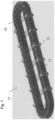
- the linear motor system 11 comprises several segments 13, which are arranged in a row, so that a continuous and in this case circular movement of the runners 15 along a guide track 17 is possible.
- the transport system 11 comprises several runners 15, the individual Transport elements of the transport system 11 and which are connected by means of the (eg in Fig.3 shown) electromagnets in the segments 13 can be moved independently of one another along the guide track 17.
- the segments 13 together with the runners 15 form a linear motor.
- Fig.2 shows a curved section of the linear motor system 11 in an enlarged view.
- a runner 15 is shown, which can be moved along the guide track 17 by means of the segments 13.
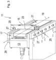
- Fig.3 the linear motor system 11 is shown in a sectional view and enlarged.
- a runner 15 is visible, which is movably guided on the guide track 17.
- the runner 15 can be moved along a guide axis 19 or movement axis.
- the runner 15 is controlled to move along the guide axis 19 by a plurality of electromagnets 21, which are arranged on the guide track 17 and evenly distributed along it.
- the electromagnets 21 interact with a permanent magnet 23 arranged on the runner 15, which can also be referred to as a drive magnet, to drive the runner.
- the rotor 15 is mechanically guided on the guide track 17 by a roller guide. This comprises guide rollers 25 on the rotor 15 and guide rails 27 on the guide track 17. The rotor 15 is held on the guide track 17 in particular via the permanent magnet 23.
- the linear motor system 11 also comprises a position detection device 29.
- This can be designed, for example, as a series of a plurality of magnetic sensors that extends along the guide track 17.
- a permanent magnet 31 can be provided, which can also be referred to as a position magnet and in Fig.2 is visible.
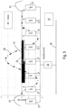
- Fig.4 shows a schematic representation of the circuit for regulating the current in coils of the electromagnets 21.
- the electromagnets 21 are each electrically connected to a direct current power supply network 35 by means of their own switching converter 33.
- a control device 37 controls the flow of current through the electromagnets 21, in particular through the transistors 34 shown in the switching converters 33 and a control electronics 36 connected upstream of the transistors 34.
- the transistors 34 optionally establish an electrical connection between the power supply network 35 and the electromagnets 21.
- a current sensor 38 and a voltage sensor 42 are also connected to the power supply network 35. A signal from the current sensor 38 is fed to the control device 37.
- a signal, in particular digitized, from the voltage sensor 42 is fed to a model 44 consisting of a negative impedance ("1/R_damp") and a damping capacitor ("1/C_damp").
- the model of the damping capacitor is in a feedback loop and is subtracted from the signal from the voltage sensor 42.
- the model 44 together with a control loop of the control device 37, causes a damping of oscillations in the power supply network 35. It is understood that the model 44 is arranged in the control device and is shown externally only for better understanding.
- Fig.5 shows the electromagnets 21 of a segment 13 relative to the rotor 15 or to its drive magnet 23.
- the north and south poles of the drive magnet 23 are shown separately.
- a drive current 39 is shown via the various electromagnets 21.
- the drive current 39 shown is a superposition of the currents impressed in the various electromagnets 21, with positive and negative values indicating the direction of the current.
- the drive current 39 shown leads to a movement of the rotor 15.
- control device 37 can also be designed to detect current induced by the drive magnet 23 of the rotor 15 in the electromagnet 21 and to use this to determine or verify the position of the rotor 15.
- FIG.6 An embodiment for generating the damping current 41 is shown in the diagrams of Fig.6 shown.
- the damping current 41 is impressed into one or more electromagnets 21, which are also supplied with drive current 39.
- the dotted line shows a typical course of the drive current 39 when the rotor 15 is moved over the coil at a constant speed and force.
- the current course of the drive current 39 is usually selected so that the force effect of all electromagnets 21 together on the rotor is as linear as possible, while at the same time a low total current is aimed for. It is understood that alternative current profiles of the drive current 39 are possible.
- damping current 41 applies in the case that the rotor 15 moves at a constant speed over the electromagnets 21, whereby the damping current 41 does not exert any force on the rotor 15 in the direction of movement.
- the resulting coil current 43 is shown as a dash-dot line, which results from the drive current 39 and the damping current 41 as the current actually flowing into the electromagnet 21.
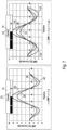
- Fig.7 shows another embodiment for implementing the damping current 41.
- a "normal" current distribution of the drive current 39 is shown.
- the induced coil current 40 is also shown.
- a resulting coil current 43 can be achieved, which is shown in the right diagram of Fig.7 It can be seen that larger current components are further away from the rotor 15, whereby the force acting on the rotor 15 remains the same due to the greater distance, but there is the possibility of storing additional electrical energy in the electromagnets 21 of the linear motor system.
- Fig.8 shows the selection of an electromagnet 21 for the damping current based on an induced current.
- the dotted line shows a typical course of the drive current 39 (as in Fig.6 ) when the rotor 15 is moved over the coil with constant speed and force.
- the solid line shows a possible course of an induced voltage (EMF) 45 in the electromagnets 21 (ie in their coils) when a rotor 15 is moved at a constant speed over the electromagnets 21.
- EMF induced voltage
- the curve shape of the induced voltage 45 is a measure of how efficiently a current flow in an electromagnet generates a force on the rotor 15. In the rotor position shown, the induced voltage 45 is in the Fig.8
- the voltage is greatest in the electromagnet 21 called “coil 2" (18 V). In “coil 0" and “coil 4", which are arranged symmetrically to "coil 2", it is significantly smaller (-1.56 V).
- the ratio of the induced voltages is 11.5.
Landscapes
- Engineering & Computer Science (AREA)
- Power Engineering (AREA)
- Physics & Mathematics (AREA)
- Chemical & Material Sciences (AREA)
- Combustion & Propulsion (AREA)
- Electromagnetism (AREA)
- Microelectronics & Electronic Packaging (AREA)
- Control Of Linear Motors (AREA)
- Linear Motors (AREA)
Claims (14)
- Système de moteur linéaire (11), en particulier système de transport, par exemple système multi-chariots, comprenant :une voie de guidage (17) ayant une pluralité d'électroaimants (21) répartis le long de la voie de guidage (17) et alimentés en énergie électrique par un réseau d'alimentation électrique (35) ;au moins un curseur (15) qui est guidé sur la voie de guidage (17) et peut se déplacer le long de celle-ci et qui comprend un aimant d'entraînement (23) destiné à coopérer avec les électroaimants (21) de la voie de guidage (17) pour déplacer le curseur (15) ; etun dispositif de commande (37) conçu pour commander le mouvement du curseur (15) par rapport à la voie de guidage (17) en alimentant une partie des électroaimants en un courant d'entraînement (39),dans lequelle dispositif de commande (37) est conçu pour alimenter au moins une partie des électroaimants (21) en un courant d'atténuation (41) de telle sorte que l'alimentation en courant d'atténuation (41) ne résulte d'une part en aucun mouvement supplémentaire et/ou en aucune modification du mouvement du curseur (15) généré par le courant d'entraînement (39) le long de la voie de guidage (17) et/ou d'autre part en aucune force supplémentaire sur le curseur (15) et/ou en aucune modification de la force générée par le courant d'entraînement (39) sur le curseur (15), en particulier le long de la voie de guidage (17),l'alimentation en courant d'atténuation (41) est effectuée afin de réduire les oscillations et/ou les fluctuations de courant et de tension dans le réseau d'alimentation électrique (35),caractérisé en ce quele courant d'entraînement (39) et le courant d'atténuation (41) se superposent dans un ou plusieurs électroaimants (21).
- Système de moteur linéaire (11) selon la revendication 1,
caractérisé en ce que
le dispositif de commande (37) est conçu pour alimenter en courant d'atténuation (41) au moins une partie des électroaimants (21) qui, à un moment donné, ne provoquent aucun mouvement du curseur (15), en particulier le long de la voie de guidage (17). - Système de moteur linéaire (11) selon la revendication 1 ou 2,
caractérisé en ce que
le dispositif de commande (37) est conçu pour appliquer le courant d'atténuation (41) aux électroaimants qui ne sont pas traversés par le courant d'entraînement (39) à un moment donné. - Système de moteur linéaire (11) selon la revendication 1 ou 2,
caractérisé en ce que
le dispositif de commande (37) est conçu pour appliquer le courant d'atténuation (41) aux électroaimants (21) qui sont également alimentés en courant d'entraînement (39). - Système de moteur linéaire (11) selon l'une des revendications précédentes 1, 2 ou 4,
caractérisé en ce que
le dispositif de commande (37) est conçu pour réduire le courant d'entraînement (39) dans l'un au moins des électroaimants (21) au moyen du courant d'atténuation (41) et, en contrepartie, pour appliquer le courant d'atténuation (41) à un électroaimant (21) voisin afin de compenser une modification de l'action de la force sur le curseur (15) due à la réduction du courant d'entraînement (39). - Système de moteur linéaire (11) selon l'une des revendications précédentes,
caractérisé en ce que
le courant d'entraînement (39) et le courant d'atténuation (41) appliqués aux électroaimants (21), pris ensemble, sont au moins temporairement plus importants que le courant d'entraînement (39) seul, et, grâce au courant total plus important, de l'énergie est stockée dans les électroaimants (21). - Système de moteur linéaire (11) selon l'une des revendications précédentes,
caractérisé en ce que
les électroaimants (21) sont connectés au réseau d'alimentation électrique (35) au moyen de convertisseurs de commutation, les convertisseurs de commutation agissant de préférence chacun comme une charge à puissance constante. - Système de moteur linéaire (11) selon l'une des revendications précédentes,
caractérisé en ce que
pour sélectionner au moins un électroaimant (21) qui doit être alimenté en courant d'atténuation, le dispositif de commande (37) est conçu pour prendre en compte une tension d'induction provoquée par le curseur (15) dans plusieurs des électroaimants (21) lors du mouvement du curseur (15). - Système de moteur linéaire (11) selon l'une des revendications précédentes,
caractérisé en ce quele dispositif de commande (37) est conçu pour générer au moins temporairement un courant d'atténuation négatif (41) pour au moins un électroaimant (21), afin d'injecter de l'énergie électrique dans le réseau d'alimentation électrique (35),
et/ouen ce que le dispositif de commande (37) est conçu pour générer au moins temporairement un courant d'atténuation positif (41) pour au moins un électroaimant (21), afin d'évacuer de l'énergie électrique du réseau d'alimentation électrique (35). - Système de moteur linéaire (11) selon l'une des revendications précédentes,
caractérisé en ce que
le système de moteur linéaire (11) comporte plusieurs segments (13) comprenant chacun plusieurs des électroaimants (21), le dispositif de commande (37) étant réparti sur plusieurs des segments (13). - Système de moteur linéaire (11) selon l'une des revendications précédentes,
caractérisé en ce que
il est prévu un capteur qui détecte le courant et/ou la tension dans le réseau d'alimentation électrique (35) et le/la convertit en un signal de capteur, le dispositif de commande (37) comprenant un circuit de régulation pour générer le courant d'atténuation (41), le circuit de régulation incluant une reproduction d'une impédance négative et une reproduction d'un élément d'atténuation. - Système de moteur linéaire (11) selon la revendication 11, caractérisé en ce que
le circuit de régulation comprend une logique qui détermine le courant d'atténuation (41) pour les électroaimants (21) à partir d'un signal de régulation, en particulier en se basant sur d'autres conditions limites. - Système de moteur linéaire (11) selon l'une des revendications précédentes,
caractérisé en ce que
le système de moteur linéaire (11) comprend plusieurs segments (13), chaque segment (13) comprenant plusieurs desdits électroaimants (21), lesdits segments (13) étant disposés en série et constituant une voie de guidage périphérique (17), ladite voie de guidage (17) étant disposée sur un côté extérieur des segments respectifs (13). - Procédé de fonctionnement d'un système de moteur linéaire (11), en particulier d'un système de transport, par exemple d'un système multi-chariots, le système de moteur linéaire (11) comprenant :une voie de guidage (17) ayant une pluralité d'électroaimants (21) répartis le long de la voie de guidage (17) et alimentés en énergie électrique par un réseau d'alimentation électrique (35) ;au moins un curseur (15) qui est guidé sur la voie de guidage (17) et peut se déplacer le long de celle-ci et qui comprend un aimant d'entraînement (23) destiné à coopérer avec les électroaimants (21) de la voie de guidage (17) pour déplacer le curseur (15) ; etun dispositif de commande (37) conçu pour commander le mouvement du curseur (15) par rapport à la voie de guidage (17) en alimentant une partie des électroaimants en un courant d'entraînement (39),dans lequelau moins une partie des électroaimants (21) sont alimentés en courant d'atténuation (41) de telle sorte que l'alimentation en courant d'atténuation (41) ne résulte d'une part en aucun mouvement supplémentaire et/ou en aucune modification du mouvement du curseur (15) généré par le courant d'entraînement (39) le long de la voie de guidage (17) et/ou d'autre part en aucune force supplémentaire sur le curseur (15) et/ou en aucune modification de la force générée par le courant d'entraînement (39) sur le curseur (15), en particulier le long de la voie de guidage (17),l'alimentation en courant d'atténuation (41) est effectuée afin de réduire les oscillations et/ou les fluctuations de courant et de tension dans le réseau d'alimentation électrique (35),caractérisé en ce quele courant d'entraînement (39) et le courant d'atténuation (41) se superposent dans un ou plusieurs électroaimants (21).
Priority Applications (3)
| Application Number | Priority Date | Filing Date | Title |
|---|---|---|---|
| EP20306457.1A EP4007157B1 (fr) | 2020-11-27 | 2020-11-27 | Système de moteur linéaire et méthode de fonctionnement d'un tel système |
| US17/456,599 US11735990B2 (en) | 2020-11-27 | 2021-11-26 | Linear motor system and method for operating |
| CN202111431126.0A CN114567139B (zh) | 2020-11-27 | 2021-11-29 | 线性电动机系统和运行线性电动机系统的方法 |
Applications Claiming Priority (1)
| Application Number | Priority Date | Filing Date | Title |
|---|---|---|---|
| EP20306457.1A EP4007157B1 (fr) | 2020-11-27 | 2020-11-27 | Système de moteur linéaire et méthode de fonctionnement d'un tel système |
Publications (2)
| Publication Number | Publication Date |
|---|---|
| EP4007157A1 EP4007157A1 (fr) | 2022-06-01 |
| EP4007157B1 true EP4007157B1 (fr) | 2024-08-14 |
Family
ID=73698762
Family Applications (1)
| Application Number | Title | Priority Date | Filing Date |
|---|---|---|---|
| EP20306457.1A Active EP4007157B1 (fr) | 2020-11-27 | 2020-11-27 | Système de moteur linéaire et méthode de fonctionnement d'un tel système |
Country Status (3)
| Country | Link |
|---|---|
| US (1) | US11735990B2 (fr) |
| EP (1) | EP4007157B1 (fr) |
| CN (1) | CN114567139B (fr) |
Families Citing this family (1)
| Publication number | Priority date | Publication date | Assignee | Title |
|---|---|---|---|---|
| EP4498594A1 (fr) * | 2023-07-26 | 2025-01-29 | Schneider Electric Industries Sas | Procédé de commande synchrone de deux moteurs |
Family Cites Families (13)
| Publication number | Priority date | Publication date | Assignee | Title |
|---|---|---|---|---|
| GB1165704A (en) * | 1965-08-27 | 1969-10-01 | Nat Res Dev | Elektromagnetic Control Apparatus |
| US20080303355A1 (en) * | 2007-03-16 | 2008-12-11 | Orlo James Fiske | Rail motor system and method |
| DE102008061205A1 (de) * | 2008-11-18 | 2010-05-20 | Institut für Luft- und Kältetechnik gemeinnützige Gesellschaft mbH | Elektrodynamischer Linearschwingmotor |
| CN102459947B (zh) * | 2009-05-26 | 2015-03-04 | Skf私人有限公司 | 具有集成被动阻尼器的电磁致动器及具有电磁致动器的悬挂系统和车辆 |
| EP2654199B1 (fr) | 2012-04-18 | 2017-08-02 | Siemens Aktiengesellschaft | Procédé et dispositif de stabilisation d'une tension électrique au moyen d'une régulation orientée champ |
| KR20130138976A (ko) * | 2012-06-12 | 2013-12-20 | 숭실대학교산학협력단 | 에너지 포집 기능을 가지는 코일 와전류 감쇠기 및 이를 구비한 모션 스테이지 |
| AU2015409486A1 (en) * | 2015-09-22 | 2017-11-09 | Fawaz AL-JOBORY | Extendable compact structure having one or plurality of permanent magnets for driving electrical generator |
| DE202016104643U1 (de) * | 2016-08-24 | 2017-08-25 | Beckhoff Automation Gmbh | Statorvorrichtung für einen Linearmotor und lineares Antriebssystem |
| US10734912B2 (en) * | 2016-08-24 | 2020-08-04 | Beckhoff Automation Gmbh | Stator device for a linear motor, linear drive system, and method for operating a stator device |
| DE102016220686A1 (de) * | 2016-10-21 | 2018-04-26 | Robert Bosch Gmbh | Verfahren und Schaltungsanordnung zum Ermitteln einer Position eines beweglichen Ankers eines elektromagnetischen Aktors |
| EP3487049B1 (fr) * | 2017-11-17 | 2024-01-17 | Schneider Electric Industries SAS | Moteur linéaire á flux transversal |
| EP3569528B1 (fr) * | 2018-05-16 | 2020-07-29 | Schneider Electric Industries SAS | Système de transport |
| EP3653551B1 (fr) * | 2018-11-16 | 2026-03-04 | Schneider Electric Industries SAS | Système de moteur linéaire |
-
2020
- 2020-11-27 EP EP20306457.1A patent/EP4007157B1/fr active Active
-
2021
- 2021-11-26 US US17/456,599 patent/US11735990B2/en active Active
- 2021-11-29 CN CN202111431126.0A patent/CN114567139B/zh active Active
Also Published As
| Publication number | Publication date |
|---|---|
| US20220173646A1 (en) | 2022-06-02 |
| CN114567139A (zh) | 2022-05-31 |
| CN114567139B (zh) | 2026-04-14 |
| EP4007157A1 (fr) | 2022-06-01 |
| US11735990B2 (en) | 2023-08-22 |
Similar Documents
| Publication | Publication Date | Title |
|---|---|---|
| EP3547530B1 (fr) | Procédé de fonctionnement d'un dispositif de transport en forme de moteur linéaire à stator long | |
| EP4049886B1 (fr) | Procédé de réglage de la force normale d'une unité de transport d'un moteur linéaire à stator long | |
| DE112010003861B4 (de) | Linearmotor-Antriebssystem und Linearmotor-Steuerverfahren | |
| EP0151296A2 (fr) | Circuit de commande pour un moteur pas à pas | |
| DE19616393B4 (de) | Proportionalmagnetventil-Steuersystem | |
| WO2015140155A1 (fr) | Dispositif de transport pour déplacer et/ou positionner des objets | |
| DE102011113000A1 (de) | Transportvorrichtung | |
| DE112010003456T5 (de) | Verteilte-anordnung-linearmotor und steuerungsverfahren eines verteilte-anordnung-linearmotors | |
| WO2017089167A1 (fr) | Procédé de commande et/ou de régulation d'un dispositif d'entraînement linéaire, dispositif de commande, dispositif d'entraînement linéaire et installation | |
| DE3331953C2 (de) | Elektromagnetischer Linearantrieb | |
| EP4007157B1 (fr) | Système de moteur linéaire et méthode de fonctionnement d'un tel système | |
| EP1150416A1 (fr) | Entrainement direct electrodynamique d'un moteur linéaire | |
| WO2009106060A1 (fr) | Procédé de coupe destiné à réduire un impact de coupe | |
| EP3569528A1 (fr) | Système de transport | |
| EP3625079A1 (fr) | Aiguillage magnétique pour un système de transport | |
| DE102013001295A1 (de) | Verfahren zur Steuerung eines Linearmotors | |
| DE102021124121A1 (de) | Energieübertragung in einem linearen Transportsystem | |
| EP1661236B1 (fr) | Procede et circuit permettant de determiner sans detecteur des etats de charge de moteurs lineaires synchrones | |
| DE2460551C3 (de) | Steueranordnung für einen Schwingspulenmotor | |
| DE102012012762A1 (de) | Einrichtung und Verfahren zur Bestimmung von Positionen eines Rotors in elektrischen Maschinen | |
| EP3621188A1 (fr) | Système de moteur linéaire | |
| EP0894292B1 (fr) | Organe de regulation electronique pour un systeme de regulation d'une boite de vitesses | |
| DE19633740B4 (de) | Verfahren und Einrichtung zur Ansteuerung eines eigentaktierten Schrittmotors | |
| WO1998018067A1 (fr) | Unite de regulation d'un mecanisme d'entrainement direct a phases multiples et procede de commande d'un tel mecanisme d'entrainement | |
| DE2723646A1 (de) | Einrichtung zur steuerung der erregung einer gleichstrommaschine |
Legal Events
| Date | Code | Title | Description |
|---|---|---|---|
| PUAI | Public reference made under article 153(3) epc to a published international application that has entered the european phase |
Free format text: ORIGINAL CODE: 0009012 |
|
| STAA | Information on the status of an ep patent application or granted ep patent |
Free format text: STATUS: THE APPLICATION HAS BEEN PUBLISHED |
|
| AK | Designated contracting states |
Kind code of ref document: A1 Designated state(s): AL AT BE BG CH CY CZ DE DK EE ES FI FR GB GR HR HU IE IS IT LI LT LU LV MC MK MT NL NO PL PT RO RS SE SI SK SM TR |
|
| STAA | Information on the status of an ep patent application or granted ep patent |
Free format text: STATUS: REQUEST FOR EXAMINATION WAS MADE |
|
| 17P | Request for examination filed |
Effective date: 20220803 |
|
| RBV | Designated contracting states (corrected) |
Designated state(s): AL AT BE BG CH CY CZ DE DK EE ES FI FR GB GR HR HU IE IS IT LI LT LU LV MC MK MT NL NO PL PT RO RS SE SI SK SM TR |
|
| GRAP | Despatch of communication of intention to grant a patent |
Free format text: ORIGINAL CODE: EPIDOSNIGR1 |
|
| STAA | Information on the status of an ep patent application or granted ep patent |
Free format text: STATUS: GRANT OF PATENT IS INTENDED |
|
| RIC1 | Information provided on ipc code assigned before grant |
Ipc: H02P 25/062 20160101ALI20240104BHEP Ipc: H02P 6/00 20160101AFI20240104BHEP |
|
| INTG | Intention to grant announced |
Effective date: 20240124 |
|
| GRAJ | Information related to disapproval of communication of intention to grant by the applicant or resumption of examination proceedings by the epo deleted |
Free format text: ORIGINAL CODE: EPIDOSDIGR1 |
|
| STAA | Information on the status of an ep patent application or granted ep patent |
Free format text: STATUS: REQUEST FOR EXAMINATION WAS MADE |
|
| GRAP | Despatch of communication of intention to grant a patent |
Free format text: ORIGINAL CODE: EPIDOSNIGR1 |
|
| STAA | Information on the status of an ep patent application or granted ep patent |
Free format text: STATUS: GRANT OF PATENT IS INTENDED |
|
| INTC | Intention to grant announced (deleted) | ||
| INTG | Intention to grant announced |
Effective date: 20240312 |
|
| GRAS | Grant fee paid |
Free format text: ORIGINAL CODE: EPIDOSNIGR3 |
|
| GRAA | (expected) grant |
Free format text: ORIGINAL CODE: 0009210 |
|
| STAA | Information on the status of an ep patent application or granted ep patent |
Free format text: STATUS: THE PATENT HAS BEEN GRANTED |
|
| AK | Designated contracting states |
Kind code of ref document: B1 Designated state(s): AL AT BE BG CH CY CZ DE DK EE ES FI FR GB GR HR HU IE IS IT LI LT LU LV MC MK MT NL NO PL PT RO RS SE SI SK SM TR |
|
| REG | Reference to a national code |
Ref country code: GB Ref legal event code: FG4D Free format text: NOT ENGLISH |
|
| REG | Reference to a national code |
Ref country code: CH Ref legal event code: EP |
|
| REG | Reference to a national code |
Ref country code: DE Ref legal event code: R096 Ref document number: 502020008863 Country of ref document: DE |
|
| REG | Reference to a national code |
Ref country code: IE Ref legal event code: FG4D Free format text: LANGUAGE OF EP DOCUMENT: GERMAN |
|
| REG | Reference to a national code |
Ref country code: LT Ref legal event code: MG9D |
|
| REG | Reference to a national code |
Ref country code: NL Ref legal event code: MP Effective date: 20240814 |
|
| PG25 | Lapsed in a contracting state [announced via postgrant information from national office to epo] |
Ref country code: NO Free format text: LAPSE BECAUSE OF FAILURE TO SUBMIT A TRANSLATION OF THE DESCRIPTION OR TO PAY THE FEE WITHIN THE PRESCRIBED TIME-LIMIT Effective date: 20241114 |
|
| PG25 | Lapsed in a contracting state [announced via postgrant information from national office to epo] |
Ref country code: GR Free format text: LAPSE BECAUSE OF FAILURE TO SUBMIT A TRANSLATION OF THE DESCRIPTION OR TO PAY THE FEE WITHIN THE PRESCRIBED TIME-LIMIT Effective date: 20241115 Ref country code: NL Free format text: LAPSE BECAUSE OF FAILURE TO SUBMIT A TRANSLATION OF THE DESCRIPTION OR TO PAY THE FEE WITHIN THE PRESCRIBED TIME-LIMIT Effective date: 20240814 Ref country code: PT Free format text: LAPSE BECAUSE OF FAILURE TO SUBMIT A TRANSLATION OF THE DESCRIPTION OR TO PAY THE FEE WITHIN THE PRESCRIBED TIME-LIMIT Effective date: 20241216 Ref country code: PL Free format text: LAPSE BECAUSE OF FAILURE TO SUBMIT A TRANSLATION OF THE DESCRIPTION OR TO PAY THE FEE WITHIN THE PRESCRIBED TIME-LIMIT Effective date: 20240814 Ref country code: FI Free format text: LAPSE BECAUSE OF FAILURE TO SUBMIT A TRANSLATION OF THE DESCRIPTION OR TO PAY THE FEE WITHIN THE PRESCRIBED TIME-LIMIT Effective date: 20240814 |
|
| PG25 | Lapsed in a contracting state [announced via postgrant information from national office to epo] |
Ref country code: BG Free format text: LAPSE BECAUSE OF FAILURE TO SUBMIT A TRANSLATION OF THE DESCRIPTION OR TO PAY THE FEE WITHIN THE PRESCRIBED TIME-LIMIT Effective date: 20240814 |
|
| PG25 | Lapsed in a contracting state [announced via postgrant information from national office to epo] |
Ref country code: LV Free format text: LAPSE BECAUSE OF FAILURE TO SUBMIT A TRANSLATION OF THE DESCRIPTION OR TO PAY THE FEE WITHIN THE PRESCRIBED TIME-LIMIT Effective date: 20240814 |
|
| PG25 | Lapsed in a contracting state [announced via postgrant information from national office to epo] |
Ref country code: IS Free format text: LAPSE BECAUSE OF FAILURE TO SUBMIT A TRANSLATION OF THE DESCRIPTION OR TO PAY THE FEE WITHIN THE PRESCRIBED TIME-LIMIT Effective date: 20241214 |
|
| PG25 | Lapsed in a contracting state [announced via postgrant information from national office to epo] |
Ref country code: HR Free format text: LAPSE BECAUSE OF FAILURE TO SUBMIT A TRANSLATION OF THE DESCRIPTION OR TO PAY THE FEE WITHIN THE PRESCRIBED TIME-LIMIT Effective date: 20240814 |
|
| PG25 | Lapsed in a contracting state [announced via postgrant information from national office to epo] |
Ref country code: ES Free format text: LAPSE BECAUSE OF FAILURE TO SUBMIT A TRANSLATION OF THE DESCRIPTION OR TO PAY THE FEE WITHIN THE PRESCRIBED TIME-LIMIT Effective date: 20240814 Ref country code: RS Free format text: LAPSE BECAUSE OF FAILURE TO SUBMIT A TRANSLATION OF THE DESCRIPTION OR TO PAY THE FEE WITHIN THE PRESCRIBED TIME-LIMIT Effective date: 20241114 |
|
| PG25 | Lapsed in a contracting state [announced via postgrant information from national office to epo] |
Ref country code: RS Free format text: LAPSE BECAUSE OF FAILURE TO SUBMIT A TRANSLATION OF THE DESCRIPTION OR TO PAY THE FEE WITHIN THE PRESCRIBED TIME-LIMIT Effective date: 20241114 Ref country code: PT Free format text: LAPSE BECAUSE OF FAILURE TO SUBMIT A TRANSLATION OF THE DESCRIPTION OR TO PAY THE FEE WITHIN THE PRESCRIBED TIME-LIMIT Effective date: 20241216 Ref country code: PL Free format text: LAPSE BECAUSE OF FAILURE TO SUBMIT A TRANSLATION OF THE DESCRIPTION OR TO PAY THE FEE WITHIN THE PRESCRIBED TIME-LIMIT Effective date: 20240814 Ref country code: NO Free format text: LAPSE BECAUSE OF FAILURE TO SUBMIT A TRANSLATION OF THE DESCRIPTION OR TO PAY THE FEE WITHIN THE PRESCRIBED TIME-LIMIT Effective date: 20241114 Ref country code: NL Free format text: LAPSE BECAUSE OF FAILURE TO SUBMIT A TRANSLATION OF THE DESCRIPTION OR TO PAY THE FEE WITHIN THE PRESCRIBED TIME-LIMIT Effective date: 20240814 Ref country code: LV Free format text: LAPSE BECAUSE OF FAILURE TO SUBMIT A TRANSLATION OF THE DESCRIPTION OR TO PAY THE FEE WITHIN THE PRESCRIBED TIME-LIMIT Effective date: 20240814 Ref country code: IS Free format text: LAPSE BECAUSE OF FAILURE TO SUBMIT A TRANSLATION OF THE DESCRIPTION OR TO PAY THE FEE WITHIN THE PRESCRIBED TIME-LIMIT Effective date: 20241214 Ref country code: HR Free format text: LAPSE BECAUSE OF FAILURE TO SUBMIT A TRANSLATION OF THE DESCRIPTION OR TO PAY THE FEE WITHIN THE PRESCRIBED TIME-LIMIT Effective date: 20240814 Ref country code: GR Free format text: LAPSE BECAUSE OF FAILURE TO SUBMIT A TRANSLATION OF THE DESCRIPTION OR TO PAY THE FEE WITHIN THE PRESCRIBED TIME-LIMIT Effective date: 20241115 Ref country code: FI Free format text: LAPSE BECAUSE OF FAILURE TO SUBMIT A TRANSLATION OF THE DESCRIPTION OR TO PAY THE FEE WITHIN THE PRESCRIBED TIME-LIMIT Effective date: 20240814 Ref country code: ES Free format text: LAPSE BECAUSE OF FAILURE TO SUBMIT A TRANSLATION OF THE DESCRIPTION OR TO PAY THE FEE WITHIN THE PRESCRIBED TIME-LIMIT Effective date: 20240814 Ref country code: BG Free format text: LAPSE BECAUSE OF FAILURE TO SUBMIT A TRANSLATION OF THE DESCRIPTION OR TO PAY THE FEE WITHIN THE PRESCRIBED TIME-LIMIT Effective date: 20240814 |
|
| PG25 | Lapsed in a contracting state [announced via postgrant information from national office to epo] |
Ref country code: SM Free format text: LAPSE BECAUSE OF FAILURE TO SUBMIT A TRANSLATION OF THE DESCRIPTION OR TO PAY THE FEE WITHIN THE PRESCRIBED TIME-LIMIT Effective date: 20240814 Ref country code: RO Free format text: LAPSE BECAUSE OF FAILURE TO SUBMIT A TRANSLATION OF THE DESCRIPTION OR TO PAY THE FEE WITHIN THE PRESCRIBED TIME-LIMIT Effective date: 20240814 Ref country code: DK Free format text: LAPSE BECAUSE OF FAILURE TO SUBMIT A TRANSLATION OF THE DESCRIPTION OR TO PAY THE FEE WITHIN THE PRESCRIBED TIME-LIMIT Effective date: 20240814 |
|
| PG25 | Lapsed in a contracting state [announced via postgrant information from national office to epo] |
Ref country code: EE Free format text: LAPSE BECAUSE OF FAILURE TO SUBMIT A TRANSLATION OF THE DESCRIPTION OR TO PAY THE FEE WITHIN THE PRESCRIBED TIME-LIMIT Effective date: 20240814 |
|
| PG25 | Lapsed in a contracting state [announced via postgrant information from national office to epo] |
Ref country code: CZ Free format text: LAPSE BECAUSE OF FAILURE TO SUBMIT A TRANSLATION OF THE DESCRIPTION OR TO PAY THE FEE WITHIN THE PRESCRIBED TIME-LIMIT Effective date: 20240814 |
|
| PG25 | Lapsed in a contracting state [announced via postgrant information from national office to epo] |
Ref country code: SK Free format text: LAPSE BECAUSE OF FAILURE TO SUBMIT A TRANSLATION OF THE DESCRIPTION OR TO PAY THE FEE WITHIN THE PRESCRIBED TIME-LIMIT Effective date: 20240814 |
|
| REG | Reference to a national code |
Ref country code: DE Ref legal event code: R097 Ref document number: 502020008863 Country of ref document: DE |
|
| PLBE | No opposition filed within time limit |
Free format text: ORIGINAL CODE: 0009261 |
|
| STAA | Information on the status of an ep patent application or granted ep patent |
Free format text: STATUS: NO OPPOSITION FILED WITHIN TIME LIMIT |
|
| REG | Reference to a national code |
Ref country code: CH Ref legal event code: PL |
|
| PG25 | Lapsed in a contracting state [announced via postgrant information from national office to epo] |
Ref country code: MC Free format text: LAPSE BECAUSE OF FAILURE TO SUBMIT A TRANSLATION OF THE DESCRIPTION OR TO PAY THE FEE WITHIN THE PRESCRIBED TIME-LIMIT Effective date: 20240814 |
|
| PG25 | Lapsed in a contracting state [announced via postgrant information from national office to epo] |
Ref country code: LU Free format text: LAPSE BECAUSE OF NON-PAYMENT OF DUE FEES Effective date: 20241127 |
|
| REG | Reference to a national code |
Ref country code: CH Ref legal event code: PL |
|
| 26N | No opposition filed |
Effective date: 20250515 |
|
| GBPC | Gb: european patent ceased through non-payment of renewal fee |
Effective date: 20241127 |
|
| PG25 | Lapsed in a contracting state [announced via postgrant information from national office to epo] |
Ref country code: CH Free format text: LAPSE BECAUSE OF NON-PAYMENT OF DUE FEES Effective date: 20241130 |
|
| REG | Reference to a national code |
Ref country code: BE Ref legal event code: MM Effective date: 20241130 |
|
| PG25 | Lapsed in a contracting state [announced via postgrant information from national office to epo] |
Ref country code: SE Free format text: LAPSE BECAUSE OF FAILURE TO SUBMIT A TRANSLATION OF THE DESCRIPTION OR TO PAY THE FEE WITHIN THE PRESCRIBED TIME-LIMIT Effective date: 20240814 |
|
| PG25 | Lapsed in a contracting state [announced via postgrant information from national office to epo] |
Ref country code: GB Free format text: LAPSE BECAUSE OF NON-PAYMENT OF DUE FEES Effective date: 20241127 Ref country code: BE Free format text: LAPSE BECAUSE OF NON-PAYMENT OF DUE FEES Effective date: 20241130 |
|
| PG25 | Lapsed in a contracting state [announced via postgrant information from national office to epo] |
Ref country code: IE Free format text: LAPSE BECAUSE OF NON-PAYMENT OF DUE FEES Effective date: 20241127 |
|
| PGFP | Annual fee paid to national office [announced via postgrant information from national office to epo] |
Ref country code: AT Payment date: 20260113 Year of fee payment: 5 |
|
| PGFP | Annual fee paid to national office [announced via postgrant information from national office to epo] |
Ref country code: IT Payment date: 20251128 Year of fee payment: 6 |
|
| PGFP | Annual fee paid to national office [announced via postgrant information from national office to epo] |
Ref country code: FR Payment date: 20251128 Year of fee payment: 6 |
|
| PG25 | Lapsed in a contracting state [announced via postgrant information from national office to epo] |
Ref country code: HU Free format text: LAPSE BECAUSE OF FAILURE TO SUBMIT A TRANSLATION OF THE DESCRIPTION OR TO PAY THE FEE WITHIN THE PRESCRIBED TIME-LIMIT; INVALID AB INITIO Effective date: 20201127 |
|
| PG25 | Lapsed in a contracting state [announced via postgrant information from national office to epo] |
Ref country code: CY Free format text: LAPSE BECAUSE OF FAILURE TO SUBMIT A TRANSLATION OF THE DESCRIPTION OR TO PAY THE FEE WITHIN THE PRESCRIBED TIME-LIMIT; INVALID AB INITIO Effective date: 20201127 |
|
| PGFP | Annual fee paid to national office [announced via postgrant information from national office to epo] |
Ref country code: DE Payment date: 20260128 Year of fee payment: 6 |