EP4007472B1 - Dispositif d'affichage d'image et procédé d'affichage d'image - Google Patents
Dispositif d'affichage d'image et procédé d'affichage d'image Download PDFInfo
- Publication number
- EP4007472B1 EP4007472B1 EP19938124.5A EP19938124A EP4007472B1 EP 4007472 B1 EP4007472 B1 EP 4007472B1 EP 19938124 A EP19938124 A EP 19938124A EP 4007472 B1 EP4007472 B1 EP 4007472B1
- Authority
- EP
- European Patent Office
- Prior art keywords
- image
- component
- display
- relevant information
- predetermined
- Prior art date
- Legal status (The legal status is an assumption and is not a legal conclusion. Google has not performed a legal analysis and makes no representation as to the accuracy of the status listed.)
- Active
Links
Images




Classifications
-
- G—PHYSICS
- G06—COMPUTING OR CALCULATING; COUNTING
- G06F—ELECTRIC DIGITAL DATA PROCESSING
- G06F3/00—Input arrangements for transferring data to be processed into a form capable of being handled by the computer; Output arrangements for transferring data from processing unit to output unit, e.g. interface arrangements
- G06F3/01—Input arrangements or combined input and output arrangements for interaction between user and computer
- G06F3/048—Interaction techniques based on graphical user interfaces [GUI]
- G06F3/0484—Interaction techniques based on graphical user interfaces [GUI] for the control of specific functions or operations, e.g. selecting or manipulating an object, an image or a displayed text element, setting a parameter value or selecting a range
- G06F3/04845—Interaction techniques based on graphical user interfaces [GUI] for the control of specific functions or operations, e.g. selecting or manipulating an object, an image or a displayed text element, setting a parameter value or selecting a range for image manipulation, e.g. dragging, rotation, expansion or change of colour
-
- H—ELECTRICITY
- H05—ELECTRIC TECHNIQUES NOT OTHERWISE PROVIDED FOR
- H05K—PRINTED CIRCUITS; CASINGS OR CONSTRUCTIONAL DETAILS OF ELECTRIC APPARATUS; MANUFACTURE OF ASSEMBLAGES OF ELECTRICAL COMPONENTS
- H05K13/00—Apparatus or processes specially adapted for manufacturing or adjusting assemblages of electric components
- H05K13/08—Monitoring manufacture of assemblages
- H05K13/081—Integration of optical monitoring devices in assembly lines; Processes using optical monitoring devices specially adapted for controlling devices or machines in assembly lines
- H05K13/0813—Controlling of single components prior to mounting, e.g. orientation, component geometry
-
- G—PHYSICS
- G06—COMPUTING OR CALCULATING; COUNTING
- G06F—ELECTRIC DIGITAL DATA PROCESSING
- G06F3/00—Input arrangements for transferring data to be processed into a form capable of being handled by the computer; Output arrangements for transferring data from processing unit to output unit, e.g. interface arrangements
- G06F3/01—Input arrangements or combined input and output arrangements for interaction between user and computer
- G06F3/048—Interaction techniques based on graphical user interfaces [GUI]
- G06F3/0481—Interaction techniques based on graphical user interfaces [GUI] based on specific properties of the displayed interaction object or a metaphor-based environment, e.g. interaction with desktop elements like windows or icons, or assisted by a cursor's changing behaviour or appearance
- G06F3/0482—Interaction with lists of selectable items, e.g. menus
-
- G—PHYSICS
- G06—COMPUTING OR CALCULATING; COUNTING
- G06F—ELECTRIC DIGITAL DATA PROCESSING
- G06F3/00—Input arrangements for transferring data to be processed into a form capable of being handled by the computer; Output arrangements for transferring data from processing unit to output unit, e.g. interface arrangements
- G06F3/01—Input arrangements or combined input and output arrangements for interaction between user and computer
- G06F3/048—Interaction techniques based on graphical user interfaces [GUI]
- G06F3/0484—Interaction techniques based on graphical user interfaces [GUI] for the control of specific functions or operations, e.g. selecting or manipulating an object, an image or a displayed text element, setting a parameter value or selecting a range
-
- G—PHYSICS
- G06—COMPUTING OR CALCULATING; COUNTING
- G06F—ELECTRIC DIGITAL DATA PROCESSING
- G06F3/00—Input arrangements for transferring data to be processed into a form capable of being handled by the computer; Output arrangements for transferring data from processing unit to output unit, e.g. interface arrangements
- G06F3/01—Input arrangements or combined input and output arrangements for interaction between user and computer
- G06F3/048—Interaction techniques based on graphical user interfaces [GUI]
- G06F3/0484—Interaction techniques based on graphical user interfaces [GUI] for the control of specific functions or operations, e.g. selecting or manipulating an object, an image or a displayed text element, setting a parameter value or selecting a range
- G06F3/04842—Selection of displayed objects or displayed text elements
-
- G—PHYSICS
- G06—COMPUTING OR CALCULATING; COUNTING
- G06F—ELECTRIC DIGITAL DATA PROCESSING
- G06F3/00—Input arrangements for transferring data to be processed into a form capable of being handled by the computer; Output arrangements for transferring data from processing unit to output unit, e.g. interface arrangements
- G06F3/01—Input arrangements or combined input and output arrangements for interaction between user and computer
- G06F3/048—Interaction techniques based on graphical user interfaces [GUI]
- G06F3/0484—Interaction techniques based on graphical user interfaces [GUI] for the control of specific functions or operations, e.g. selecting or manipulating an object, an image or a displayed text element, setting a parameter value or selecting a range
- G06F3/04847—Interaction techniques to control parameter settings, e.g. interaction with sliders or dials
-
- H—ELECTRICITY
- H05—ELECTRIC TECHNIQUES NOT OTHERWISE PROVIDED FOR
- H05K—PRINTED CIRCUITS; CASINGS OR CONSTRUCTIONAL DETAILS OF ELECTRIC APPARATUS; MANUFACTURE OF ASSEMBLAGES OF ELECTRICAL COMPONENTS
- H05K13/00—Apparatus or processes specially adapted for manufacturing or adjusting assemblages of electric components
- H05K13/04—Mounting of components, e.g. of leadless components
- H05K13/0404—Pick-and-place heads or apparatus, e.g. with jaws
- H05K13/0408—Incorporating a pick-up tool
- H05K13/041—Incorporating a pick-up tool having multiple pick-up tools
Definitions
- the present specification discloses an image display device and an image display method.
- Patent Literature 1 describes a device in which a mounting head includes multiple nozzles, an image is captured when the mounting head passes above an imaging unit in a state in which a component is held in each nozzle, and the image is transmitted to a management computer.
- the management computer can display an image on a display screen such as a display.
- JP 2006202934 A relates to inspection of components on suction nozzles in a component mounting machine. Images are taken and automatically analyzed for abnormalities. When an abnormality is detected an enlarged image of the designated suction nozzle is shown. When a worker presses a display switch portion, an enlarged image of the image portion related to the switch portion is shown, too.
- WO 2018131066 A1 relates to error handling in a component mounter. When the device becomes inactive due to an error, information is shown to a user who can then resume production and/or edit production information such as shape data of the component.
- Patent Literature 1 WO 2018/122903
- a main object of the present disclosure is to cause an operator to appropriately select a desired component from multiple components included in an image, so that an operation relating to the selected component can be performed.
- the present disclosure has taken following means to achieve the main object described above.
- a first image display device of the present disclosure is an image display device configured to display, on a display screen, a predetermined image captured in a state in which multiple components to be mounted on a board are held by a mounting head, including: a display control section configured to selectably display, on the display screen, relevant information relating to the multiple components in association with each component, together with the predetermined image, and when a predetermined operation involving selection of any of the relevant information is performed by an operator, display an enlarged image of one component corresponding to the selected relevant information of the predetermined image being displayed.
- the first image display device selectably displays relevant information relating to multiple components in association with each component, together with a predetermined image captured in a state in which multiple components to be mounted on a board are held by a mounting head. Then, when the predetermined operation involving the selection of any of the relevant information is performed by the operator, an enlarged image of one component corresponding to the selected relevant information of the predetermined image being displayed is displayed. As a result, the operator can cause the enlarged image of a desired component to be displayed by performing the predetermined operation involving the selection of the relevant information from the multiple components in the predetermined image while paying attention to the relevant information. Therefore, it is possible to easily perform the component confirmation operation using the enlarged image without making a selection error of the component to be enlarged.
- Fig. 1 is an explanatory view illustrating an example of component mounting system 10
- Fig. 2 is an explanatory view schematically illustrating configurations of mounting head 33 and part camera 28 of mounting device 20.
- component mounting system 10 includes mounting device 20 that picks up component P (refer to Fig. 2 ) from a reel, a tray, or the like and mounts component P on a board, inspection device 40 that inspects a board on which multiple components P are mounted, and management device 80 that manages information relating to mounting device 20 and inspection device 40.
- Mounting device 20, inspection device 40, and management device 80 are connected to LAN 12 serving as a network, and can exchange information with each other. Although one mounting device 20 and one inspection device 40 are illustrated in Fig. 1 , multiple mounting devices 20 and inspection devices 40 may be provided.
- a left-right direction (X-axis), a front-rear direction (Y-axis), and an up-down direction (Z-axis) are illustrated as in Fig. 1 .
- the term "mounting” includes disposing, attaching, inserting, bonding, adhering, or the like component P on the board.
- Mounting device 20 includes mounting control unit 21 that executes various controls, board processing unit 30 that conveys and fixes the board in an X-direction, and mounting processing unit 32 that disposes component P on the board.
- mounting device 20 includes supply unit 27 that supplies component P accommodated in the reel, the tray, or the like to a predetermined supply position, part camera 28 that captures an image of component P, input and output interface (I/F) 29 for performing communication, and operation panel 36 capable of displaying various information and performing various input operations by an operator.
- supply unit 27 that supplies component P accommodated in the reel, the tray, or the like to a predetermined supply position
- part camera 28 that captures an image of component P
- input and output interface (I/F) 29 for performing communication
- operation panel 36 capable of displaying various information and performing various input operations by an operator.
- Mounting processing unit 32 includes mounting head 33, multiple suction nozzles 34 attached to mounting head 33 via a nozzle holding body, and moving mechanism 35 that moves mounting head 33 in XY-directions.
- Mounting head 33 is configured as a rotary head in which multiple suction nozzles 34 (for example, 12 suction nozzles) are arranged at equal intervals on the same circumference.
- Mounting head 33 incorporates a Z-axis motor (not illustrated) and adjusts a height of suction nozzle 34 by the Z-axis motor.
- Suction nozzle 34 uses a pressure to pick up component P to a nozzle tip or to separate component P picked up to the nozzle tip.
- Moving mechanism 35 includes an X-direction slider (not illustrated) movable in the X-direction and a Y-direction slider (not illustrated) movable in a Y-direction. As the X-direction slider moves or the Y-direction slider of moving mechanism 35 moves, mounting head 33 moves in the X-direction or the Y-direction. Each slider is driven by a drive motor.
- part camera 28 captures an image of a component held (picked up) by multiple suction nozzles 34 of mounting head 33 from below to generate an image.
- part camera 28 includes lighting section 28a having multiple LEDs (not illustrated) attached to an inner surface of a housing having a truncated inverted octagonal pyramid with upper and lower surfaces opened, and camera main body 28b disposed below the housing.
- camera main body 28b includes an imaging element that outputs electric charge generated by light reception, an image processing section that generates image data based on the output electric charge, and the like.
- Part camera 28 outputs the generated image data to mounting control unit 21.
- FIG. 3 is an explanatory view illustrating an example of an image captured by part camera 28.
- suction nozzles 34 are arranged on the same circumference at equal intervals, components P picked up by suction nozzles 34 are also arranged on the same circumference at equal intervals and appear in an image.
- an image is captured such that multiple components P fall within one image, each component P appears small in the image.
- Operation panel 36 includes display screen 37 that displays various information and operation button 38 that receives an input operation of the operator.
- Display screen 37 is configured as a liquid crystal display and displays mounting information, setting information, images, and the like of mounting device 20.
- Operation button 38 includes a cursor button that moves a selection cursor in display screen 37 in the up-down direction and the left-right direction, a decision button that determines a selection content, a cancel button that cancels an input, and the like.
- Mounting control unit 21 is configured as a microprocessor centered on CPU 22 and includes ROM 23 that stores a processing program, RAM 24 that is used as an operation area, HDD 25 that stores various data, and the like, which are connected via a bus.
- Mounting control unit 21 outputs a control signal to board processing unit 30, mounting processing unit 32, and supply unit 27 via input and output interface 29, outputs an imaging signal to part camera 28, outputs a display signal to operation panel 36, and outputs information to management device 80.
- Mounting control unit 21 inputs a signal from board processing unit 30, mounting processing unit 32, and supply unit 27 via input and output interface 29, acquires an image captured by part camera 28, inputs an operation signal from operation panel 36, or receives information from management device 80.
- mounting control unit 21 acquires mounting information including conditions relating to the mounting of each component P from management device 80, and executes mounting processing.
- mounting control unit 21 causes each suction nozzle 34 of mounting head 33 to pick up component P, causes moving mechanism 35 to move mounting head 33 onto part camera 28, and causes part camera 28 to capture the image of component P picked up (held) by each suction nozzle 34.
- Mounting control unit 21 calculates a positional deviation amount or a rotational deviation amount of each component P by performing the image processing on the captured image, corrects a mounting position or a mounting direction based on the deviation amounts, and mounts each component P at the mounting position on the board.
- mounting control unit 21 recognizes a shape and a center position of each component P in the image, and calculates the positional deviation amount of component P with respect to the pickup position of each suction nozzle 34 or the rotational deviation amount of component P with respect to a predetermined reference direction. In addition, mounting control unit 21 determines whether there are shape errors such as dimensional defects, deformation, chipping, and adhesion of foreign matter in an outer shape based on whether the shape of component P in the image is within a predetermined permissible range with respect to the shape data stored in advance.
- shape errors such as dimensional defects, deformation, chipping, and adhesion of foreign matter in an outer shape based on whether the shape of component P in the image is within a predetermined permissible range with respect to the shape data stored in advance.
- mounting control unit 21 determines whether there is a positional deviation error or a rotational deviation error based on whether the positional deviation amount or the rotational deviation amount of component P is within a predetermined permissible range. Further, mounting control unit 21 determines whether there is a pickup error based on whether component P is recognized from the captured image.
- mounting control unit 21 transmits the entire image of multiple components P captured by part camera 28 and the relevant information relating to components P to management device 80. Management device 80 stores the received entire image and the relevant information in HDD 85.
- Fig. 4 is an explanatory view illustrating an example of relevant information 86.
- Relevant information 86 includes an image ID of the entire image captured by part camera 28, the nozzle number of each suction nozzle 34, the component type of picked up component P, the disposition position of component P, and the image processing result.
- the image processing result includes the positional deviation amount or the rotational deviation amount of component P described above, an error code indicating the type of error in a case in which an error has occurred, and the like.
- the same relevant information as in Fig. 4 may be stored in HDD 25 of mounting control unit 21.
- Management device 80 includes control device 81 and manages mounting device 20 and inspection device 40.
- Control device 81 is configured as a microprocessor centered on CPU 82 and includes ROM 83 for storing a processing program, RAM 84 used as a operation area, HDD 85 for storing various data, and the like, which are connected via a bus.
- Management device 80 includes input device 87 such as a keyboard and a mouse for the operator to input various instructions, display 90 for displaying various information, and input and output interface (I/F) 89 for performing communication.
- HDD 85 stores various information used for mounting in mounting device 20 and inspection in inspection device 40.
- HDD 85 stores various software such as display software for displaying various images such as the entire image of component P captured by part camera 28 of mounting device 20, and edit software for editing shape data used for the image processing of component P.
- Fig. 5 is a flowchart illustrating an example of an image display relevant processing routine. This routine is stored in HDD 85 of management device 80 and is executed by CPU 82 of control device 81 in a case in which an instruction to display a display selection screen on display 90 is issued by an operation input of input device 87 by the operator.
- CPU 82 displays a display selection screen on display 90 (S100) and waits for the operator to make a selection (S110).
- a display on display 90 of the confirmation screen for confirming component P in which an error has occurred
- a display on display 90 of the edit screen for editing the shape data of component P.
- the operator can also edit the shape data of component P after first confirming component P in which the error has occurred on the confirmation screen.
- CPU 82 determines whether the display of the confirmation screen is selected (S120) when the selection is made by the operator, executes the confirmation display processing (S130) when it is determined that the display of the confirmation screen is selected, and terminates the image display relevant processing routine.
- CPU 82 executes the edit display processing (S140) and terminates the image display relevant processing routine.
- Fig. 6 is a flowchart illustrating an example of the confirmation display processing.
- Fig. 7 is an explanatory view illustrating an example of confirmation screen 91 including entire image 92 of component P and information list display image 93.
- information list display image 93 is displayed on confirmation screen 91 beside entire image 92 that is the same as the image (refer to Fig. 3 ) captured by part camera 28.
- cursor 91a that can be selected and inputted by input device 87 is displayed on confirmation screen 91.
- information list display image 93 the component type of component P and the error code in a case in which an error has occurred are displayed in association with each other in the order of nozzle numbers [1] to [12] of respective suction nozzles 34. Accordingly, the relevant information is selectably listed in the order corresponding to the clockwise display position (nozzle position) of component P in entire image 92. In information list display image 93, each piece of relevant information can be selected by cursor 91a.
- Fig. 8 is an explanatory view illustrating an example of confirmation screen 91 including enlarged image 94 of component P and information list display image 93.
- Fig. 8 illustrates a state in which enlarged image 94 of component P picked up by suction nozzle 34 of nozzle number [8] is displayed in place of entire image 92, in a case in which the relevant information of nozzle number [8] is selected by the operation of cursor 91a.
- enlarged image 94 displays image processing results such as positional deviation amount (X, Y) and rotational deviation amount ⁇ of component P, edit button image 95a, and return button image 95b.
- Edit button image 95a is a button image for starting the edit of the shape data of enlarged component P
- return button image 95b is a button image for returning from enlarged image 94 to entire image 92. These can be selected by operating cursor 91a. The display of the image processing result may be omitted.
- CPU 82 waits for return button image 95b to be operated (S215) or edit button image 95a to be operated (S220).
- return button image 95b is operated, CPU 82 returns to S200 to return the display from enlarged image 94 to entire image 92.
- edit button image 95a is operated, CPU 82 displays edit screen 97 for editing the shape data of enlarged and displayed component P on display 90 (S225), and accepts the correction of the shape data by the operator (S230). Since the edit of the shape data is a function of the edit software described above, CPU 82 displays edit screen 97 together with activation of the edit software in S225.
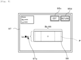
- Fig. 9 is an explanatory view illustrating an example of edit screen 97 including shape data image 98 of component P.
- shape data image 98 indicating the outer shape of component P is displayed in a transparent manner by solid lines, and an enlarged image of component P is displayed so as to align the center with shape data image 98 to be overlapped.
- the enlarged image of component P is the same image as enlarged image 94 except that the inclination is corrected.
- Width Wx in the X-direction and length Ly in the Y-direction are displayed in shape data image 98 so as to be editable. The operator can select either width Wx or length Ly with cursor 97a, and input (correct) a numerical value by an operation input of input device 87.
- CPU 82 accepts the correction by changing the shape (size) of shape data image 98 in accordance with the numerical value inputted by the operator.
- the component type and numerical values of width Wx and length Ly before the edit is started confirmation button image 95c, and return button image 95d are displayed.
- Confirmation button image 95c is a button image for starting a confirmation test of the shape data
- return button image 95d is a button image for returning from edit screen 97 to confirmation screen 91. These can be selected by operating cursor 97a.
- CPU 82 waits for confirmation button image 95c to be operated (S235) or return button image 95d to be operated (S240).
- return button image 95d When return button image 95d is operated, CPU 82 returns to S210 without reflecting the correction and returns the display from edit screen 97 to confirmation screen 91 including enlarged image 94.
- confirmation button image 95c when confirmation button image 95c is operated, CPU 82 executes a confirmation test for confirming the outer shape of component P in the image using the edited shape data in which the numerical values of width Wx, length Ly, and the like are corrected (S245).
- CPU 82 applies the corrected shape data to another component P having the same shape data, such as the same component type, to perform a confirmation test as to whether the dimension is defective, and displays the confirmation result on the screen.
- CPU 82 determines whether the operator approves the confirmation result (S250) and if the operator does not approve the result, the processing returns to S225 to display the edit screen.
- CPU 82 stores the shape data after the edit (S255), reflects the edit content, and terminates the confirmation display processing.
- CPU 82 permits mounting device 20 to restart production when the processing is terminated by reflecting the edit content in a case in which mounting device 20 stops the production due to the occurrence of the image processing error.
- Fig. 10 is a flowchart illustrating an example of the edit display processing.
- CPU 82 displays, on display 90, confirmation screen 91B including entire image 92 of component P and information correspondence display image 99 in which relevant information 86 is displayed in association with the periphery of each component P (S300).
- Fig. 11 is an explanatory view illustrating an example of confirmation screen 91B including entire image 92 of component P and information correspondence display image 99.
- information correspondence display image 99 associated with the periphery of each component P is displayed on confirmation screen 91B in same entire image 92 as the image (refer to Fig. 3 ) captured by part camera 28.
- Information correspondence display image 99 is an image in a circular shape surrounding component P, in which information correspondence display images 99s in a normal mode indicating that an error has not occurred are displayed by solid lines, and information correspondence display images 99e in an error mode indicating that an error has occurred are displayed by dotted lines.
- information correspondence display image 99 displays the presence or absence of the error of corresponding component P by a difference in line type, but may be displayed by a difference in color, a difference in line thickness, a difference in shape, or the like.
- cursor 91a that can be selected and inputted by input device 87 is displayed on confirmation screen 91B, so that information correspondence display image 99 can be selected.
- FIG. 12 is an explanatory view illustrating selectable area 99a in the periphery of information correspondence display image 99.
- selectable area 99a is a circular area that is once larger information correspondence display image 99 and is set in association with each information correspondence display image 99.
- selectable area 99a is illustrated by one-dot chain lines in Fig. 12 , selectable area 99a is not actually displayed on the screen.
- cursor 91a is moved into any of the selectable areas 99a by the operation of the operator, information correspondence display image 99 corresponding to selectable area 99a can be selected even outside the area of information correspondence display image 99.
- Selectable area 99a may be sized from the center position of each suction nozzle 34 and the size of component P so as not to overlap with each other, or may be sized from an interval between adjacent suction nozzles 34.
- CPU 82 waits for the relevant information to be selected by whether any of information correspondence display images 99 is selected (S305), whether selectable area 99a in the periphery of information correspondence display image 99 is selected (S310).
- CPU 82 highlights component P for which the relevant information is selected and component P of which the shape data is the same (S315).
- Fig. 13 is an explanatory view illustrating a state in which information correspondence display image 99 is highlighted.
- FIG. 13 illustrates a case in which, since cursor 91a has moved into selectable area 99a at the three o'clock position in the drawing, the relevant information of information correspondence display image 99 surrounded by selectable area 99a is selected.
- information correspondence display image 99 corresponding to component P having the same shape data here, three information correspondence display images 99 including information correspondence display images 99 at positions at the one o'clock and the two o'clock in the drawing are highlighted by thick lines. Components P having different shape data are not highlighted and remain in the original display.
- CPU 82 highlights information correspondence display image 99. Therefore, when selecting one component P and editing the shape data, the operator can easily grasp which other component P the edited result is reflected in and which component P is commonly subjected to the confirmation test.
- CPU 82 waits for a return operation to be performed (S320) or a selection confirmation operation to be performed by an operation input of input device 87 (S325).
- the return operation is, for example, an operation of moving cursor 91a to the outside of selectable area 99a.
- the selection confirmation operation is, for example, a predetermined operation of input device 87 such as clicking the mouse.
- CPU 82 returns the processing to S300.
- the selection confirmation operation is performed, CPU 82 displays edit screen 97 for editing the shape data of currently selected component P on display 90 (S330), and accepts the correction of the shape data by the operator (S335).
- CPU 82 waits for confirmation button image 95c to be operated (S340) or return button image 95d to be operated (S345), and when return button image 95d is operated, the processing returns to S300 to return the display to confirmation screen 91B.
- confirmation button image 95c is operated, CPU 82 executes a confirmation test with the shape data after the edit (S350) and determines whether the operator approved the result of the confirmation test (S355). If the operator does not approve the result, CPU 82 returns to S330 to display the edit screen and if the operator approves the result, CPU 82 stores the shape data after the edit (S360), reflects the edited content, and terminates the confirmation display processing.
- Management device 80 of the present embodiment corresponds to the image display device of the present disclosure
- display 90 corresponds to the display screen
- CPU 82 of control device 81 corresponds to the display control section.
- management device 80 including CPU 82 and display 90 for performing the confirmation display processing in S130 of the image display relevant processing routine corresponds to the first image display device
- management device 80 including CPU 82 and display 90 for performing the edit display processing in S140 of the image display relevant processing routine corresponds to the second image display device.
- an example of the image display method of the present disclosure is also described by explaining the operation of management device 80.
- Management device 80 described above displays, on display 90, confirmation screen 91 including entire image 92 captured by part camera 28 and information list display image 93 in which the relevant information of component P is listed. Since management device 80 displays enlarged image 94 of one component P corresponding to the relevant information selected by the operator, the operator can easily select component P to be enlarged without making a selection error of component P, and can appropriately perform the confirmation operation of component P using the enlarged image.
- management device 80 displays edit button image 95a together with enlarged image 94, and displays edit screen 97 when edit button image 95a is operated, it is possible to prevent the selection error of component P of the edit target.
- the relevant information is listed in information list display image 93 in the order corresponding to the display positions of multiple components P in entire image 92, the relevant information can be selected more easily.
- management device 80 displays, on display 90, confirmation screen 91B including entire image 92 and information correspondence display image 99 in which the relevant information is associated with the periphery of each component P. Since management device 80 displays edit screen 97 of component P corresponding to information correspondence display image 99 selected by the operator, the operator can easily select component P to be edited without making a selection error of component P, so that the edit operation can be promptly started. Therefore, it is possible to prevent the operator from editing the shape data of wrong component P.
- management device 80 since management device 80 highlights information correspondence display image 99 of component P of which the shape data is the same as component P corresponding to selected information correspondence display image 99, the operator can easily grasp which other component P after edit of the shape data is reflected in.
- the periphery of information correspondence display image 99 is set as selectable area 99a, it is possible to make it easier for the operator to select the relevant information corresponding to desired component P.
- information list display image 93 and information correspondence display image 99 since the error information indicating the presence or absence of an error in component P is displayed in association with each other, the operator can easily grasp and select component P in which the error has occurred.
- confirmation screen 91 is displayed in the confirmation display processing in S130, the configuration is not limited to this and confirmation screen 91B may be displayed.
- confirmation screen 91B is displayed in the edit display processing of S140, the configuration is not limited to this and confirmation screen 91 may be displayed.
- information list display image 93 of confirmation screen 91 includes the nozzle number, the component type, and the error code, but the configuration is not limited to this and may include only the nozzle number and the error code, or may include other information such as the serial number (identification information) and the disposition position of component P, and information relating to the image processing result in information list display image 93.
- information list display image 93 the relevant information is listed in the order corresponding to the display position of component P, but the configuration is not limited to this and may be listed in the order not corresponding to the display position of component P.
- the circular image is exemplified as information correspondence display image 99, but the configuration is not limited to this and an image indicating error information may be displayed such as displaying a character or a symbol indicating an error in the periphery of error component P.
- selectable area 99a is provided in the periphery of information correspondence display image 99, the configuration is not limited to this and selectable area 99a may not be provided.
- information correspondence display image 99 corresponding to component P having the same shape data is highlighted by thick lines but the configuration is not limited to this, and may be highlighted in another display mode such as blinking or changing colors.
- the display is not limited to the highlight and the highlight may not be performed.
- enlarged image 94 of component P and edit button image 95a are displayed, and edit screen 97 is displayed by operating edit button image 95a; however, the configuration is not limited to this.
- edit screen 97 may be displayed by a predetermined operation of input device 87 such as a clicking operation of the mouse button without displaying edit button image 95a.
- input device 87 such as a clicking operation of the mouse button without displaying edit button image 95a.
- only the confirmation using enlarged image 94 of component P may be performed on confirmation screen 91, so that S220 to S255 of the confirmation display processing may be omitted.
- both the enlarged display of component P and the edit of the shape data of component P are executed but the configuration is not limited to this, and any one of them may be executed.
- S140 of the image display relevant processing routine may be omitted and S220 to S255 of the confirmation display processing may be omitted.
- S130 of the image display relevant processing routine may be omitted.
- confirmation screens 91 and 91B, and edit screen 97 being displayed on display 90 of management device 80 are exemplified, but the configuration is not limited to this and they may be displayed on display screen 37 of operation panel 36 of mounting device 20 or the operation panel of the inspection device.
- the image display device may be configured as follows.
- the display control section may operably display a predetermined edit button image together with the enlarged image of the one component, and may display an edit screen capable of editing shape data relating to the shape of the one component when the edit button image is operated by the operator. Accordingly, since the edit operation of the component of the edit target can be started as it is after the component is confirmed by the enlarged image, it is possible to prevent the selection error of the component of the edit target.
- a second image display device of the present disclosure is an image display device configured to display, on a display screen, a predetermined image captured in a state in which multiple components to be mounted on a board are held by a mounting head, the device including a display control section configured to selectably display, on the display screen, relevant information relating to the multiple components in association with each component, together with the predetermined image, and when a predetermined operation involving selection of any of the relevant information is performed by an operator, display an edit screen capable of editing shape data relating to a shape of one component corresponding to the selected relevant information of the predetermined image being displayed.
- the second image display device selectably displays relevant information relating to multiple components in association with each component, together with a predetermined image captured in a state in which multiple components to be mounted on a board are held by a mounting head.
- a predetermined operation involving the selection of any of the relevant information is performed by the operator, an edit screen, which is capable of editing shape data relating to a shape of one component corresponding to the selected relevant information of the predetermined image being displayed, is displayed.
- the operator can cause the edit screen of a desired component to be displayed by performing a predetermined operation involving the selection of the relevant information from the multiple components in the predetermined image while paying attention to the relevant information. Therefore, it is possible to appropriately perform the edit operation of the shape data of the component without making a selection error of the component of the edit target.
- the display control section may highlight the relevant information of a component having the same shape data as that of one component corresponding to the relevant information selected by the operator in the predetermined image so as to be distinguished from the relevant information of a component having different shape data from that of the one component.
- the image may be used for predetermined image processing performed on the multiple components, and the relevant information may include error information indicating that an error has occurred in the image processing.
- the operator can easily grasp the component in which the error has occurred from the relevant information and can appropriately select the component. Therefore, it is possible to promptly confirm the failure of the component from the enlarged image of the component in which the error has occurred, or to promptly edit the shape data of the component in which the error has occurred.
- the display control section may selectably list the relevant information in the order corresponding to the display positions of the multiple components in the predetermined image.
- the display control section may selectably display the relevant information at positions corresponding to display positions of the multiple components in the predetermined image, and may make a predetermined area of the periphery of the relevant information a selectable area of the relevant information. According to such a configuration, when selecting the relevant information, since a predetermined area of the periphery thereof may be selected, it is possible to make it easier for the operator to select the relevant information corresponding to the desired component.
- a first image display method of the present disclosure is an image display method for displaying, on a display screen, a predetermined image captured in a state in which multiple components to be mounted on a board are held by a mounting head, the method including: (a) a step of selectably displaying, on the display screen, relevant information relating to the multiple components in association with each component, together with the predetermined image; and (b) a step of, when a predetermined operation involving selection of any of the relevant information is performed by an operator, displaying an enlarged image of one component corresponding to the selected relevant information of the predetermined image being displayed.
- the first image display method of the present disclosure similarly to the first image display device described above, it is possible to easily perform the component confirmation operation using the enlarged image without making a selection error of the component to be enlarged.
- various modes of the first image display device may be employed, or a step for realizing each function of the first image display device may be added.
- a second image display method of the present disclosure is an image display method for displaying, on a display screen, a predetermined image captured in a state in which multiple components to be mounted on a board are held by a mounting head, the method including: (a) a step of selectably displaying, on the display screen, relevant information relating to the multiple components in association with each component, together with the predetermined image; and (b) a step of, when a predetermined operation involving selection of any of the relevant information is performed by an operator, displaying an edit screen capable of editing shape data relating to a shape of one component corresponding to the selected relevant information of the predetermined image being displayed.
- the second image display method of the present disclosure similarly to the second image display device described above, it is possible to appropriately perform the edit operation of the shape data of the component without making a selection error of the component of the edit target.
- various modes of the second image display device may be employed, or a step for realizing each function of the second image display device may be added.
- the present disclosure can be used in, for example, a technical field in which multiple components held by a mounting head are mounted on a board.
Landscapes
- Engineering & Computer Science (AREA)
- General Engineering & Computer Science (AREA)
- Theoretical Computer Science (AREA)
- Human Computer Interaction (AREA)
- Physics & Mathematics (AREA)
- General Physics & Mathematics (AREA)
- Manufacturing & Machinery (AREA)
- Microelectronics & Electronic Packaging (AREA)
- Operations Research (AREA)
- Supply And Installment Of Electrical Components (AREA)
Claims (9)
- Dispositif d'affichage d'image (90) configuré pour afficher, sur un écran d'affichage, une image prédéterminée capturée dans un état dans lequel de multiples composants à monter sur une carte sont maintenus par une tête de montage (33), le dispositif comprenant :une section de commande d'affichage configurée pour afficher sélectivement, sur l'écran d'affichage, une information pertinente (86) se rapportant aux multiples composants en association avec chaque composant, en même temps que l'image prédéterminée,caractérisé en ce quel'information pertinente affichée inclut au moins une partie d'information incluant le numéro de buse de chaque buse d'aspiration, le type de composant du composant prélevé et la position de disposition du composant, et en ce quela section de commande d'affichage est en outre configurée pour, lorsqu'une opération prédéterminée mettant en jeu la sélection d'une quelconque information pertinente (86) est réalisée par un opérateur, afficher une image agrandie d'un composant considéré correspondant à l'information pertinente sélectionnée (86) de l'image prédéterminée qui est affichée.
- Dispositif d'affichage d'image (90) selon la revendication 1,
dans lequel la section de commande d'affichage est configurée pour afficher de manière opérationnelle une image de bouton d'édition prédéterminée en même temps que l'image agrandie du composant considéré, et pour afficher un écran d'édition (97) permettant d'éditer des données de forme se rapportant à une forme du composant considéré lorsque l'image de bouton d'édition est actionnée par l'opérateur. - Dispositif d'affichage d'image (90) configuré pour afficher, sur un écran d'affichage, une image prédéterminée capturée dans un état dans lequel de multiples composants à monter sur une carte sont maintenus par une tête de montage (33), le dispositif comprenant :une section de commande d'affichage configurée pour afficher sélectivement, sur l'écran d'affichage, une information pertinente (86) se rapportant aux multiples composants en association avec chaque composant, en même temps que l'image prédéterminée,caractérisé en ce quel'information pertinente affichée inclut au moins une partie d'information incluant le numéro de buse de chaque buse d'aspiration, le type de composant du composant prélevé et la position de disposition du composant, et en ce quela section de commande d'affichage est en outre configurée pour, lorsqu'une opération prédéterminée mettant en jeu la sélection d'une quelconque information pertinente (86) est réalisée par un opérateur, afficher un écran d'édition (97) permettant d'éditer des données de forme se rapportant à une forme d'un composant considéré correspondant à l'information pertinente sélectionnée (86) de l'image prédéterminée qui est affichée.
- Dispositif d'affichage d'image (90) selon la revendication 3,
dans lequel la section de commande d'affichage est configurée pour mettre en évidence l'information pertinente (86) d'un composant présentant les mêmes données de forme que celles d'un composant considéré correspondant à l'information pertinente (86) sélectionnée par l'opérateur dans l'image prédéterminée de manière à ce qu'elle soit distinguée de l'information pertinente (86) d'un composant présentant des données de forme différentes de celles du composant considéré. - Dispositif d'affichage d'image (90) selon l'une quelconque des revendications 1 à 4,dans lequel l'image est utilisée pour un traitement d'image prédéterminé réalisé sur les multiples composants, etl'information pertinente (86) inclut une information d'erreur indiquant qu'une erreur est survenue lors du traitement d'image.
- Dispositif d'affichage d'image (90) selon l'une quelconque des revendications 1 à 5,
dans lequel la section de commande d'affichage est configurée pour lister sélectivement l'information pertinente (86) selon l'ordre correspondant à des positions d'affichage des multiples composants dans l'image prédéterminée. - Dispositif d'affichage d'image (90) selon l'une quelconque des revendications 1 à 5,
dans lequel la section de commande d'affichage est configurée pour afficher sélectivement l'information pertinente (86) en des positions correspondant à des positions d'affichage des multiples composants dans l'image prédéterminée, et pour constituer une zone prédéterminée d'une périphérie de l'information pertinente (86) en tant que zone pouvant être sélectionnée de l'information pertinente (86). - Procédé d'affichage d'image pour afficher, sur un écran d'affichage, une image prédéterminée capturée dans un état dans lequel de multiples composants à monter sur une carte sont maintenus par une tête de montage (33), le procédé comprenant :(a) une étape consistant à afficher sélectivement, sur l'écran d'affichage, une information pertinente (86) se rapportant aux multiples composants en association avec chaque composant, en même temps que l'image prédéterminée ;caractérisé en ce quel'information pertinente affichée inclut au moins une partie d'information incluant le numéro de buse de chaque buse d'aspiration, le type de composant du composant prélevé et la position de disposition du composant, et en ce quele procédé d'affichage d'image comprend en outre (b) une étape consistant à, lorsqu'une opération prédéterminée mettant en jeu la sélection d'une quelconque information pertinente (86) est réalisée par un opérateur, afficher une image agrandie d'un composant considéré correspondant à l'information pertinente sélectionnée (86) de l'image prédéterminée qui est affichée.
- Procédé d'affichage d'image pour afficher, sur un écran d'affichage, une image prédéterminée capturée dans un état dans lequel de multiples composants à monter sur une carte sont maintenus par une tête de montage (33), le procédé comprenant :(a) une étape consistant à afficher sélectivement, sur l'écran d'affichage, une information pertinente (86) se rapportant aux multiples composants en association avec chaque composant, en même temps que l'image prédéterminée ;caractérisé en ce quel'information pertinente affichée inclut au moins une partie d'information incluant le numéro de buse de chaque buse d'aspiration, le type de composant du composant prélevé et la position de disposition du composant, et en ce quele procédé d'affichage d'image comprend en outre (b) une étape consistant à, lorsqu'une opération prédéterminée mettant en jeu la sélection d'une quelconque information pertinente (86) est réalisée par un opérateur, afficher un écran d'édition (97) permettant d'éditer des données de forme se rapportant à une forme d'un composant considéré correspondant à l'information pertinente sélectionnée (86) de l'image prédéterminée qui est affichée.
Applications Claiming Priority (1)
| Application Number | Priority Date | Filing Date | Title |
|---|---|---|---|
| PCT/JP2019/028624 WO2021014524A1 (fr) | 2019-07-22 | 2019-07-22 | Dispositif d'affichage d'image et procédé d'affichage d'image |
Publications (3)
| Publication Number | Publication Date |
|---|---|
| EP4007472A1 EP4007472A1 (fr) | 2022-06-01 |
| EP4007472A4 EP4007472A4 (fr) | 2022-07-20 |
| EP4007472B1 true EP4007472B1 (fr) | 2024-05-01 |
Family
ID=74193488
Family Applications (1)
| Application Number | Title | Priority Date | Filing Date |
|---|---|---|---|
| EP19938124.5A Active EP4007472B1 (fr) | 2019-07-22 | 2019-07-22 | Dispositif d'affichage d'image et procédé d'affichage d'image |
Country Status (5)
| Country | Link |
|---|---|
| US (1) | US11809695B2 (fr) |
| EP (1) | EP4007472B1 (fr) |
| JP (1) | JP7295240B2 (fr) |
| CN (1) | CN114041110B (fr) |
| WO (1) | WO2021014524A1 (fr) |
Family Cites Families (39)
| Publication number | Priority date | Publication date | Assignee | Title |
|---|---|---|---|---|
| JP3954550B2 (ja) * | 2003-09-03 | 2007-08-08 | オリンパス株式会社 | 画像表示プログラム、画像表示装置、画像表示方法 |
| CN100393097C (zh) * | 2003-11-27 | 2008-06-04 | 富士胶片株式会社 | 图像编辑装置及其方法 |
| JP4886989B2 (ja) * | 2005-01-20 | 2012-02-29 | 株式会社日立ハイテクインスツルメンツ | 電子部品装着装置 |
| US7404151B2 (en) * | 2005-01-26 | 2008-07-22 | Attenex Corporation | System and method for providing a dynamic user interface for a dense three-dimensional scene |
| JP4784269B2 (ja) * | 2005-11-04 | 2011-10-05 | オムロン株式会社 | 画像処理装置 |
| WO2007069471A1 (fr) * | 2005-12-14 | 2007-06-21 | Yappa Corporation | Dispositif d'affichage d'images |
| JP4834449B2 (ja) * | 2006-04-18 | 2011-12-14 | 富士機械製造株式会社 | 電子部品装着ヘッド及び電子部品装着装置 |
| JP4845832B2 (ja) * | 2007-08-07 | 2011-12-28 | キヤノン株式会社 | 撮像装置および制御方法 |
| JP5213431B2 (ja) * | 2007-12-18 | 2013-06-19 | キヤノン株式会社 | 画像処理装置、その制御方法及びプログラム |
| DE112009000375T5 (de) * | 2008-02-21 | 2011-05-19 | Panasonic Corporation, Kadoma-shi | Verfahren zum Bestimmen der Montagebedingungen |
| JP5182121B2 (ja) * | 2009-01-27 | 2013-04-10 | オムロン株式会社 | 基板外観検査用のライブラリデータの作成方法および検査データ作成方法 |
| EP2435679A4 (fr) * | 2009-05-27 | 2014-05-14 | Energy Compression Llc | Stockage d'énergie à air comprimé à adsorption améliorée |
| JP5562711B2 (ja) * | 2010-04-28 | 2014-07-30 | 株式会社日立ハイテクインスツルメンツ | 電子部品装着方法及び電子部品装着装置 |
| US8555192B2 (en) * | 2010-06-03 | 2013-10-08 | Microsoft Corporation | Sketching and searching application for idea generation |
| JP5665648B2 (ja) * | 2011-05-09 | 2015-02-04 | 富士機械製造株式会社 | 部品装着ヘッドの吸着ノズルにおける被吸着物検知方法および部品装着装置 |
| JP5924978B2 (ja) * | 2012-02-28 | 2016-05-25 | キヤノン株式会社 | 画像処理装置および画像処理方法 |
| JP6075910B2 (ja) * | 2012-07-25 | 2017-02-08 | Juki株式会社 | 情報管理システムおよび情報提供方法 |
| JP6348494B2 (ja) * | 2013-07-30 | 2018-06-27 | 株式会社Fuji | 生産設備 |
| JP6411028B2 (ja) * | 2014-01-17 | 2018-10-24 | 株式会社Fuji | 管理装置 |
| CN106664825B (zh) * | 2014-07-28 | 2019-05-03 | 株式会社富士 | 元件数据处理装置、元件数据处理方法及元件安装系统 |
| US9841870B2 (en) * | 2014-08-21 | 2017-12-12 | The Boeing Company | Integrated visualization and analysis of a complex system |
| JP6367672B2 (ja) * | 2014-09-29 | 2018-08-01 | ファスフォードテクノロジ株式会社 | 半導体若しくは電子部品実装装置及び半導体若しくは電子部品実装方法 |
| WO2016125262A1 (fr) * | 2015-02-04 | 2016-08-11 | 富士機械製造株式会社 | Dispositif de traitement d'images, système de traitement de montage, procédé de traitement d'images et programme |
| CN107852855B (zh) * | 2015-06-19 | 2020-07-03 | 雅马哈发动机株式会社 | 元件安装装置和元件安装方法 |
| DE112015006596T5 (de) * | 2015-08-17 | 2018-05-24 | Yamaha Hatsudoki Kabushiki Kaisha | Komponentenbefestigungsvorrichtung |
| DE112015007030T5 (de) * | 2015-10-14 | 2018-07-12 | Yamaha Hatsudoki Kabushiki Kaisha | Substrat-Bearbeitungssystem und Komponenten-Montagevorrichtung |
| WO2017064777A1 (fr) * | 2015-10-14 | 2017-04-20 | ヤマハ発動機株式会社 | Dispositif de montage de composant |
| WO2017064786A1 (fr) * | 2015-10-15 | 2017-04-20 | ヤマハ発動機株式会社 | Appareil de montage de composant |
| CN111465311B (zh) * | 2015-11-17 | 2021-02-26 | 株式会社富士 | 安装处理方法、安装系统及元件安装机 |
| US20190339688A1 (en) * | 2016-05-09 | 2019-11-07 | Strong Force Iot Portfolio 2016, Llc | Methods and systems for data collection, learning, and streaming of machine signals for analytics and maintenance using the industrial internet of things |
| US20210157312A1 (en) * | 2016-05-09 | 2021-05-27 | Strong Force Iot Portfolio 2016, Llc | Intelligent vibration digital twin systems and methods for industrial environments |
| US20200348662A1 (en) * | 2016-05-09 | 2020-11-05 | Strong Force Iot Portfolio 2016, Llc | Platform for facilitating development of intelligence in an industrial internet of things system |
| WO2017221659A1 (fr) * | 2016-06-20 | 2017-12-28 | マクセル株式会社 | Dispositif de capture d'images, dispositif d'affichage et système de capture et d'affichage d'images |
| CN110024511B (zh) * | 2016-12-01 | 2020-10-30 | 株式会社富士 | 元件安装生产线的生产管理系统 |
| CN110115120B (zh) | 2016-12-26 | 2020-12-25 | 株式会社富士 | 安装装置、设定装置、安装系统、安装方法及设定方法 |
| US11330745B2 (en) | 2017-01-10 | 2022-05-10 | Fuji Corporation | Management device, mounting-related device, and mounting system |
| JP2018132937A (ja) * | 2017-02-15 | 2018-08-23 | 株式会社デンソーテン | 入力装置、入力方法及び入力プログラム |
| KR102316327B1 (ko) * | 2017-04-04 | 2021-10-22 | 엘지전자 주식회사 | 가상 공간의 캡쳐 방법 및 그 전자장치 |
| US10591301B2 (en) * | 2017-10-13 | 2020-03-17 | Mapanything, Inc. | Graphical user interface (GUI) within CRM solution enabling layer views for connected devices |
-
2019
- 2019-07-22 JP JP2021534880A patent/JP7295240B2/ja active Active
- 2019-07-22 WO PCT/JP2019/028624 patent/WO2021014524A1/fr not_active Ceased
- 2019-07-22 EP EP19938124.5A patent/EP4007472B1/fr active Active
- 2019-07-22 US US17/628,488 patent/US11809695B2/en active Active
- 2019-07-22 CN CN201980098123.4A patent/CN114041110B/zh active Active
Also Published As
| Publication number | Publication date |
|---|---|
| US20220253204A1 (en) | 2022-08-11 |
| CN114041110A (zh) | 2022-02-11 |
| JPWO2021014524A1 (fr) | 2021-01-28 |
| WO2021014524A1 (fr) | 2021-01-28 |
| JP7295240B2 (ja) | 2023-06-20 |
| US11809695B2 (en) | 2023-11-07 |
| EP4007472A1 (fr) | 2022-06-01 |
| CN114041110B (zh) | 2023-11-10 |
| EP4007472A4 (fr) | 2022-07-20 |
Similar Documents
| Publication | Publication Date | Title |
|---|---|---|
| CN107041119B (zh) | 部件安装系统以及部件安装方法 | |
| JP7044935B2 (ja) | 実装システム、管理装置及びエラー対処方法 | |
| JP6411028B2 (ja) | 管理装置 | |
| CN112867252A (zh) | 一种铣刀式分板机系统的控制方法 | |
| CN116724327A (zh) | 品质改善辅助装置以及品质改善辅助系统 | |
| EP3661343B1 (fr) | Système de gestion de traitement de substrat | |
| EP4007472B1 (fr) | Dispositif d'affichage d'image et procédé d'affichage d'image | |
| JPH1197894A (ja) | 吸着ノズルの詰まり検出方法およびその装置 | |
| EP4009759B1 (fr) | Dispositif de montage, système de montage et procédé d'inspection/de montage | |
| JP4350473B2 (ja) | 品質分析システム及び品質分析方法 | |
| JP2007273519A (ja) | 認識対象の中心位置を認識する方法および装置 | |
| JP7377870B2 (ja) | 実装装置及び実装装置の制御方法 | |
| JP7593149B2 (ja) | 管理装置及び管理システム | |
| JP5191928B2 (ja) | 搭載データ作成支援装置および部品実装装置 | |
| JP2023008625A (ja) | 作業者支援システムおよび作業者支援方法 | |
| EP4002977B1 (fr) | Dispositif de montage, système de montage, et procédé de montage et d'inspection | |
| JP6715266B2 (ja) | リペア装置及びリペア方法 | |
| US12550307B2 (en) | Management device, installation-related device, installation system, management method, and method for controlling installation-related device | |
| CN113347869B (zh) | 管理装置 | |
| JP4622913B2 (ja) | 認識対象の位置を認識する方法 | |
| US20260024187A1 (en) | Image output device and image output system | |
| JP7386389B2 (ja) | 部品実装装置 | |
| US20250056778A1 (en) | Mounting device and bending determination method | |
| EP3550951B1 (fr) | Machine de travail de substrat | |
| JP2024082866A (ja) | 情報処理装置、実装システム及び情報処理方法 |
Legal Events
| Date | Code | Title | Description |
|---|---|---|---|
| STAA | Information on the status of an ep patent application or granted ep patent |
Free format text: STATUS: THE INTERNATIONAL PUBLICATION HAS BEEN MADE |
|
| PUAI | Public reference made under article 153(3) epc to a published international application that has entered the european phase |
Free format text: ORIGINAL CODE: 0009012 |
|
| STAA | Information on the status of an ep patent application or granted ep patent |
Free format text: STATUS: REQUEST FOR EXAMINATION WAS MADE |
|
| 17P | Request for examination filed |
Effective date: 20220120 |
|
| AK | Designated contracting states |
Kind code of ref document: A1 Designated state(s): AL AT BE BG CH CY CZ DE DK EE ES FI FR GB GR HR HU IE IS IT LI LT LU LV MC MK MT NL NO PL PT RO RS SE SI SK SM TR |
|
| REG | Reference to a national code |
Ref country code: DE Ref legal event code: R079 Free format text: PREVIOUS MAIN CLASS: H05K0013000000 Ipc: H05K0013040000 Ref country code: DE Ref legal event code: R079 Ref document number: 602019051764 Country of ref document: DE Free format text: PREVIOUS MAIN CLASS: H05K0013000000 Ipc: H05K0013040000 |
|
| A4 | Supplementary search report drawn up and despatched |
Effective date: 20220621 |
|
| RIC1 | Information provided on ipc code assigned before grant |
Ipc: G06F 3/0484 20220101ALI20220614BHEP Ipc: H05K 13/08 20060101ALI20220614BHEP Ipc: H05K 13/04 20060101AFI20220614BHEP |
|
| DAV | Request for validation of the european patent (deleted) | ||
| DAX | Request for extension of the european patent (deleted) | ||
| P01 | Opt-out of the competence of the unified patent court (upc) registered |
Effective date: 20230328 |
|
| GRAP | Despatch of communication of intention to grant a patent |
Free format text: ORIGINAL CODE: EPIDOSNIGR1 |
|
| STAA | Information on the status of an ep patent application or granted ep patent |
Free format text: STATUS: GRANT OF PATENT IS INTENDED |
|
| RIC1 | Information provided on ipc code assigned before grant |
Ipc: G06F 3/0484 20220101ALI20231206BHEP Ipc: G06F 3/04847 20220101ALI20231206BHEP Ipc: G06F 3/04842 20220101ALI20231206BHEP Ipc: H05K 13/08 20060101ALI20231206BHEP Ipc: H05K 13/04 20060101AFI20231206BHEP |
|
| INTG | Intention to grant announced |
Effective date: 20240103 |
|
| GRAS | Grant fee paid |
Free format text: ORIGINAL CODE: EPIDOSNIGR3 |
|
| GRAA | (expected) grant |
Free format text: ORIGINAL CODE: 0009210 |
|
| STAA | Information on the status of an ep patent application or granted ep patent |
Free format text: STATUS: THE PATENT HAS BEEN GRANTED |
|
| AK | Designated contracting states |
Kind code of ref document: B1 Designated state(s): AL AT BE BG CH CY CZ DE DK EE ES FI FR GB GR HR HU IE IS IT LI LT LU LV MC MK MT NL NO PL PT RO RS SE SI SK SM TR |
|
| REG | Reference to a national code |
Ref country code: GB Ref legal event code: FG4D |
|
| REG | Reference to a national code |
Ref country code: CH Ref legal event code: EP |
|
| REG | Reference to a national code |
Ref country code: IE Ref legal event code: FG4D |
|
| REG | Reference to a national code |
Ref country code: DE Ref legal event code: R096 Ref document number: 602019051764 Country of ref document: DE |
|
| REG | Reference to a national code |
Ref country code: LT Ref legal event code: MG9D |
|
| REG | Reference to a national code |
Ref country code: NL Ref legal event code: MP Effective date: 20240501 |
|
| PG25 | Lapsed in a contracting state [announced via postgrant information from national office to epo] |
Ref country code: IS Free format text: LAPSE BECAUSE OF FAILURE TO SUBMIT A TRANSLATION OF THE DESCRIPTION OR TO PAY THE FEE WITHIN THE PRESCRIBED TIME-LIMIT Effective date: 20240901 |
|
| PG25 | Lapsed in a contracting state [announced via postgrant information from national office to epo] |
Ref country code: BG Free format text: LAPSE BECAUSE OF FAILURE TO SUBMIT A TRANSLATION OF THE DESCRIPTION OR TO PAY THE FEE WITHIN THE PRESCRIBED TIME-LIMIT Effective date: 20240501 |
|
| PG25 | Lapsed in a contracting state [announced via postgrant information from national office to epo] |
Ref country code: HR Free format text: LAPSE BECAUSE OF FAILURE TO SUBMIT A TRANSLATION OF THE DESCRIPTION OR TO PAY THE FEE WITHIN THE PRESCRIBED TIME-LIMIT Effective date: 20240501 Ref country code: FI Free format text: LAPSE BECAUSE OF FAILURE TO SUBMIT A TRANSLATION OF THE DESCRIPTION OR TO PAY THE FEE WITHIN THE PRESCRIBED TIME-LIMIT Effective date: 20240501 |
|
| PG25 | Lapsed in a contracting state [announced via postgrant information from national office to epo] |
Ref country code: GR Free format text: LAPSE BECAUSE OF FAILURE TO SUBMIT A TRANSLATION OF THE DESCRIPTION OR TO PAY THE FEE WITHIN THE PRESCRIBED TIME-LIMIT Effective date: 20240802 |
|
| PG25 | Lapsed in a contracting state [announced via postgrant information from national office to epo] |
Ref country code: PT Free format text: LAPSE BECAUSE OF FAILURE TO SUBMIT A TRANSLATION OF THE DESCRIPTION OR TO PAY THE FEE WITHIN THE PRESCRIBED TIME-LIMIT Effective date: 20240902 |
|
| REG | Reference to a national code |
Ref country code: AT Ref legal event code: MK05 Ref document number: 1684165 Country of ref document: AT Kind code of ref document: T Effective date: 20240501 |
|
| PG25 | Lapsed in a contracting state [announced via postgrant information from national office to epo] |
Ref country code: NL Free format text: LAPSE BECAUSE OF FAILURE TO SUBMIT A TRANSLATION OF THE DESCRIPTION OR TO PAY THE FEE WITHIN THE PRESCRIBED TIME-LIMIT Effective date: 20240501 |
|
| PG25 | Lapsed in a contracting state [announced via postgrant information from national office to epo] |
Ref country code: ES Free format text: LAPSE BECAUSE OF FAILURE TO SUBMIT A TRANSLATION OF THE DESCRIPTION OR TO PAY THE FEE WITHIN THE PRESCRIBED TIME-LIMIT Effective date: 20240501 |
|
| PG25 | Lapsed in a contracting state [announced via postgrant information from national office to epo] |
Ref country code: AT Free format text: LAPSE BECAUSE OF FAILURE TO SUBMIT A TRANSLATION OF THE DESCRIPTION OR TO PAY THE FEE WITHIN THE PRESCRIBED TIME-LIMIT Effective date: 20240501 |
|
| PG25 | Lapsed in a contracting state [announced via postgrant information from national office to epo] |
Ref country code: PL Free format text: LAPSE BECAUSE OF FAILURE TO SUBMIT A TRANSLATION OF THE DESCRIPTION OR TO PAY THE FEE WITHIN THE PRESCRIBED TIME-LIMIT Effective date: 20240501 |
|
| PG25 | Lapsed in a contracting state [announced via postgrant information from national office to epo] |
Ref country code: LV Free format text: LAPSE BECAUSE OF FAILURE TO SUBMIT A TRANSLATION OF THE DESCRIPTION OR TO PAY THE FEE WITHIN THE PRESCRIBED TIME-LIMIT Effective date: 20240501 |
|
| PG25 | Lapsed in a contracting state [announced via postgrant information from national office to epo] |
Ref country code: PT Free format text: LAPSE BECAUSE OF FAILURE TO SUBMIT A TRANSLATION OF THE DESCRIPTION OR TO PAY THE FEE WITHIN THE PRESCRIBED TIME-LIMIT Effective date: 20240902 Ref country code: PL Free format text: LAPSE BECAUSE OF FAILURE TO SUBMIT A TRANSLATION OF THE DESCRIPTION OR TO PAY THE FEE WITHIN THE PRESCRIBED TIME-LIMIT Effective date: 20240501 Ref country code: NO Free format text: LAPSE BECAUSE OF FAILURE TO SUBMIT A TRANSLATION OF THE DESCRIPTION OR TO PAY THE FEE WITHIN THE PRESCRIBED TIME-LIMIT Effective date: 20240801 Ref country code: NL Free format text: LAPSE BECAUSE OF FAILURE TO SUBMIT A TRANSLATION OF THE DESCRIPTION OR TO PAY THE FEE WITHIN THE PRESCRIBED TIME-LIMIT Effective date: 20240501 Ref country code: LV Free format text: LAPSE BECAUSE OF FAILURE TO SUBMIT A TRANSLATION OF THE DESCRIPTION OR TO PAY THE FEE WITHIN THE PRESCRIBED TIME-LIMIT Effective date: 20240501 Ref country code: IS Free format text: LAPSE BECAUSE OF FAILURE TO SUBMIT A TRANSLATION OF THE DESCRIPTION OR TO PAY THE FEE WITHIN THE PRESCRIBED TIME-LIMIT Effective date: 20240901 Ref country code: HR Free format text: LAPSE BECAUSE OF FAILURE TO SUBMIT A TRANSLATION OF THE DESCRIPTION OR TO PAY THE FEE WITHIN THE PRESCRIBED TIME-LIMIT Effective date: 20240501 Ref country code: GR Free format text: LAPSE BECAUSE OF FAILURE TO SUBMIT A TRANSLATION OF THE DESCRIPTION OR TO PAY THE FEE WITHIN THE PRESCRIBED TIME-LIMIT Effective date: 20240802 Ref country code: FI Free format text: LAPSE BECAUSE OF FAILURE TO SUBMIT A TRANSLATION OF THE DESCRIPTION OR TO PAY THE FEE WITHIN THE PRESCRIBED TIME-LIMIT Effective date: 20240501 Ref country code: ES Free format text: LAPSE BECAUSE OF FAILURE TO SUBMIT A TRANSLATION OF THE DESCRIPTION OR TO PAY THE FEE WITHIN THE PRESCRIBED TIME-LIMIT Effective date: 20240501 Ref country code: BG Free format text: LAPSE BECAUSE OF FAILURE TO SUBMIT A TRANSLATION OF THE DESCRIPTION OR TO PAY THE FEE WITHIN THE PRESCRIBED TIME-LIMIT Effective date: 20240501 Ref country code: AT Free format text: LAPSE BECAUSE OF FAILURE TO SUBMIT A TRANSLATION OF THE DESCRIPTION OR TO PAY THE FEE WITHIN THE PRESCRIBED TIME-LIMIT Effective date: 20240501 Ref country code: RS Free format text: LAPSE BECAUSE OF FAILURE TO SUBMIT A TRANSLATION OF THE DESCRIPTION OR TO PAY THE FEE WITHIN THE PRESCRIBED TIME-LIMIT Effective date: 20240801 |
|
| PG25 | Lapsed in a contracting state [announced via postgrant information from national office to epo] |
Ref country code: DK Free format text: LAPSE BECAUSE OF FAILURE TO SUBMIT A TRANSLATION OF THE DESCRIPTION OR TO PAY THE FEE WITHIN THE PRESCRIBED TIME-LIMIT Effective date: 20240501 |
|
| PG25 | Lapsed in a contracting state [announced via postgrant information from national office to epo] |
Ref country code: EE Free format text: LAPSE BECAUSE OF FAILURE TO SUBMIT A TRANSLATION OF THE DESCRIPTION OR TO PAY THE FEE WITHIN THE PRESCRIBED TIME-LIMIT Effective date: 20240501 |
|
| PG25 | Lapsed in a contracting state [announced via postgrant information from national office to epo] |
Ref country code: CZ Free format text: LAPSE BECAUSE OF FAILURE TO SUBMIT A TRANSLATION OF THE DESCRIPTION OR TO PAY THE FEE WITHIN THE PRESCRIBED TIME-LIMIT Effective date: 20240501 |
|
| PG25 | Lapsed in a contracting state [announced via postgrant information from national office to epo] |
Ref country code: RO Free format text: LAPSE BECAUSE OF FAILURE TO SUBMIT A TRANSLATION OF THE DESCRIPTION OR TO PAY THE FEE WITHIN THE PRESCRIBED TIME-LIMIT Effective date: 20240501 Ref country code: SK Free format text: LAPSE BECAUSE OF FAILURE TO SUBMIT A TRANSLATION OF THE DESCRIPTION OR TO PAY THE FEE WITHIN THE PRESCRIBED TIME-LIMIT Effective date: 20240501 |
|
| PG25 | Lapsed in a contracting state [announced via postgrant information from national office to epo] |
Ref country code: SM Free format text: LAPSE BECAUSE OF FAILURE TO SUBMIT A TRANSLATION OF THE DESCRIPTION OR TO PAY THE FEE WITHIN THE PRESCRIBED TIME-LIMIT Effective date: 20240501 |
|
| PG25 | Lapsed in a contracting state [announced via postgrant information from national office to epo] |
Ref country code: SM Free format text: LAPSE BECAUSE OF FAILURE TO SUBMIT A TRANSLATION OF THE DESCRIPTION OR TO PAY THE FEE WITHIN THE PRESCRIBED TIME-LIMIT Effective date: 20240501 Ref country code: SK Free format text: LAPSE BECAUSE OF FAILURE TO SUBMIT A TRANSLATION OF THE DESCRIPTION OR TO PAY THE FEE WITHIN THE PRESCRIBED TIME-LIMIT Effective date: 20240501 Ref country code: RO Free format text: LAPSE BECAUSE OF FAILURE TO SUBMIT A TRANSLATION OF THE DESCRIPTION OR TO PAY THE FEE WITHIN THE PRESCRIBED TIME-LIMIT Effective date: 20240501 Ref country code: EE Free format text: LAPSE BECAUSE OF FAILURE TO SUBMIT A TRANSLATION OF THE DESCRIPTION OR TO PAY THE FEE WITHIN THE PRESCRIBED TIME-LIMIT Effective date: 20240501 Ref country code: DK Free format text: LAPSE BECAUSE OF FAILURE TO SUBMIT A TRANSLATION OF THE DESCRIPTION OR TO PAY THE FEE WITHIN THE PRESCRIBED TIME-LIMIT Effective date: 20240501 Ref country code: CZ Free format text: LAPSE BECAUSE OF FAILURE TO SUBMIT A TRANSLATION OF THE DESCRIPTION OR TO PAY THE FEE WITHIN THE PRESCRIBED TIME-LIMIT Effective date: 20240501 |
|
| REG | Reference to a national code |
Ref country code: DE Ref legal event code: R097 Ref document number: 602019051764 Country of ref document: DE |
|
| PG25 | Lapsed in a contracting state [announced via postgrant information from national office to epo] |
Ref country code: MC Free format text: LAPSE BECAUSE OF FAILURE TO SUBMIT A TRANSLATION OF THE DESCRIPTION OR TO PAY THE FEE WITHIN THE PRESCRIBED TIME-LIMIT Effective date: 20240501 Ref country code: IT Free format text: LAPSE BECAUSE OF FAILURE TO SUBMIT A TRANSLATION OF THE DESCRIPTION OR TO PAY THE FEE WITHIN THE PRESCRIBED TIME-LIMIT Effective date: 20240501 |
|
| REG | Reference to a national code |
Ref country code: CH Ref legal event code: PL |
|
| PLBE | No opposition filed within time limit |
Free format text: ORIGINAL CODE: 0009261 |
|
| STAA | Information on the status of an ep patent application or granted ep patent |
Free format text: STATUS: NO OPPOSITION FILED WITHIN TIME LIMIT |
|
| PG25 | Lapsed in a contracting state [announced via postgrant information from national office to epo] |
Ref country code: LU Free format text: LAPSE BECAUSE OF NON-PAYMENT OF DUE FEES Effective date: 20240722 |
|
| PG25 | Lapsed in a contracting state [announced via postgrant information from national office to epo] |
Ref country code: LU Free format text: LAPSE BECAUSE OF NON-PAYMENT OF DUE FEES Effective date: 20240722 |
|
| 26N | No opposition filed |
Effective date: 20250204 |
|
| GBPC | Gb: european patent ceased through non-payment of renewal fee |
Effective date: 20240801 |
|
| PG25 | Lapsed in a contracting state [announced via postgrant information from national office to epo] |
Ref country code: BE Free format text: LAPSE BECAUSE OF NON-PAYMENT OF DUE FEES Effective date: 20240731 Ref country code: SI Free format text: LAPSE BECAUSE OF FAILURE TO SUBMIT A TRANSLATION OF THE DESCRIPTION OR TO PAY THE FEE WITHIN THE PRESCRIBED TIME-LIMIT Effective date: 20240501 Ref country code: CH Free format text: LAPSE BECAUSE OF NON-PAYMENT OF DUE FEES Effective date: 20240731 |
|
| PG25 | Lapsed in a contracting state [announced via postgrant information from national office to epo] |
Ref country code: FR Free format text: LAPSE BECAUSE OF NON-PAYMENT OF DUE FEES Effective date: 20240731 |
|
| REG | Reference to a national code |
Ref country code: BE Ref legal event code: MM Effective date: 20240731 |
|
| PG25 | Lapsed in a contracting state [announced via postgrant information from national office to epo] |
Ref country code: GB Free format text: LAPSE BECAUSE OF NON-PAYMENT OF DUE FEES Effective date: 20240801 |
|
| PG25 | Lapsed in a contracting state [announced via postgrant information from national office to epo] |
Ref country code: IE Free format text: LAPSE BECAUSE OF NON-PAYMENT OF DUE FEES Effective date: 20240722 |
|
| PG25 | Lapsed in a contracting state [announced via postgrant information from national office to epo] |
Ref country code: SE Free format text: LAPSE BECAUSE OF FAILURE TO SUBMIT A TRANSLATION OF THE DESCRIPTION OR TO PAY THE FEE WITHIN THE PRESCRIBED TIME-LIMIT Effective date: 20240501 |
|
| PGFP | Annual fee paid to national office [announced via postgrant information from national office to epo] |
Ref country code: DE Payment date: 20250528 Year of fee payment: 7 |
|
| PG25 | Lapsed in a contracting state [announced via postgrant information from national office to epo] |
Ref country code: CY Free format text: LAPSE BECAUSE OF FAILURE TO SUBMIT A TRANSLATION OF THE DESCRIPTION OR TO PAY THE FEE WITHIN THE PRESCRIBED TIME-LIMIT; INVALID AB INITIO Effective date: 20190722 |
|
| PG25 | Lapsed in a contracting state [announced via postgrant information from national office to epo] |
Ref country code: HU Free format text: LAPSE BECAUSE OF FAILURE TO SUBMIT A TRANSLATION OF THE DESCRIPTION OR TO PAY THE FEE WITHIN THE PRESCRIBED TIME-LIMIT; INVALID AB INITIO Effective date: 20190722 |