EP4007664B1 - Transfer method, manipulation system designed therefor, and bending unit - Google Patents
Transfer method, manipulation system designed therefor, and bending unit Download PDFInfo
- Publication number
- EP4007664B1 EP4007664B1 EP20767947.3A EP20767947A EP4007664B1 EP 4007664 B1 EP4007664 B1 EP 4007664B1 EP 20767947 A EP20767947 A EP 20767947A EP 4007664 B1 EP4007664 B1 EP 4007664B1
- Authority
- EP
- European Patent Office
- Prior art keywords
- manipulator
- axis
- arm
- manipulator arm
- arms
- Prior art date
- Legal status (The legal status is an assumption and is not a legal conclusion. Google has not performed a legal analysis and makes no representation as to the accuracy of the status listed.)
- Active
Links
Images

Classifications
-
- B—PERFORMING OPERATIONS; TRANSPORTING
- B21—MECHANICAL METAL-WORKING WITHOUT ESSENTIALLY REMOVING MATERIAL; PUNCHING METAL
- B21D—WORKING OR PROCESSING OF SHEET METAL OR METAL TUBES, RODS OR PROFILES WITHOUT ESSENTIALLY REMOVING MATERIAL; PUNCHING METAL
- B21D5/00—Bending sheet metal along straight lines, e.g. to form simple curves
- B21D5/02—Bending sheet metal along straight lines, e.g. to form simple curves on press brakes without making use of clamping means
- B21D5/0281—Workpiece supporting devices
-
- B—PERFORMING OPERATIONS; TRANSPORTING
- B21—MECHANICAL METAL-WORKING WITHOUT ESSENTIALLY REMOVING MATERIAL; PUNCHING METAL
- B21D—WORKING OR PROCESSING OF SHEET METAL OR METAL TUBES, RODS OR PROFILES WITHOUT ESSENTIALLY REMOVING MATERIAL; PUNCHING METAL
- B21D43/00—Feeding, positioning or storing devices combined with, or arranged in, or specially adapted for use in connection with, apparatus for working or processing sheet metal, metal tubes or metal profiles; Associations therewith of cutting devices
- B21D43/20—Storage arrangements; Piling or unpiling
- B21D43/24—Devices for removing sheets from a stack
-
- B—PERFORMING OPERATIONS; TRANSPORTING
- B21—MECHANICAL METAL-WORKING WITHOUT ESSENTIALLY REMOVING MATERIAL; PUNCHING METAL
- B21D—WORKING OR PROCESSING OF SHEET METAL OR METAL TUBES, RODS OR PROFILES WITHOUT ESSENTIALLY REMOVING MATERIAL; PUNCHING METAL
- B21D43/00—Feeding, positioning or storing devices combined with, or arranged in, or specially adapted for use in connection with, apparatus for working or processing sheet metal, metal tubes or metal profiles; Associations therewith of cutting devices
- B21D43/02—Advancing work in relation to the stroke of the die or tool
- B21D43/026—Combination of two or more feeding devices provided for in B21D43/04 - B21D43/18
-
- B—PERFORMING OPERATIONS; TRANSPORTING
- B21—MECHANICAL METAL-WORKING WITHOUT ESSENTIALLY REMOVING MATERIAL; PUNCHING METAL
- B21D—WORKING OR PROCESSING OF SHEET METAL OR METAL TUBES, RODS OR PROFILES WITHOUT ESSENTIALLY REMOVING MATERIAL; PUNCHING METAL
- B21D43/00—Feeding, positioning or storing devices combined with, or arranged in, or specially adapted for use in connection with, apparatus for working or processing sheet metal, metal tubes or metal profiles; Associations therewith of cutting devices
- B21D43/02—Advancing work in relation to the stroke of the die or tool
- B21D43/18—Advancing work in relation to the stroke of the die or tool by means in pneumatic or magnetic engagement with the work
-
- B—PERFORMING OPERATIONS; TRANSPORTING
- B25—HAND TOOLS; PORTABLE POWER-DRIVEN TOOLS; MANIPULATORS
- B25J—MANIPULATORS; CHAMBERS PROVIDED WITH MANIPULATION DEVICES
- B25J5/00—Manipulators mounted on wheels or on carriages
- B25J5/02—Manipulators mounted on wheels or on carriages travelling along a guideway
-
- B—PERFORMING OPERATIONS; TRANSPORTING
- B25—HAND TOOLS; PORTABLE POWER-DRIVEN TOOLS; MANIPULATORS
- B25J—MANIPULATORS; CHAMBERS PROVIDED WITH MANIPULATION DEVICES
- B25J9/00—Program-controlled manipulators
- B25J9/0084—Program-controlled manipulators comprising a plurality of manipulators
-
- G—PHYSICS
- G05—CONTROLLING; REGULATING
- G05B—CONTROL OR REGULATING SYSTEMS IN GENERAL; FUNCTIONAL ELEMENTS OF SUCH SYSTEMS; MONITORING OR TESTING ARRANGEMENTS FOR SUCH SYSTEMS OR ELEMENTS
- G05B2219/00—Program-control systems
- G05B2219/30—Nc systems
- G05B2219/39—Robotics, robotics to robotics hand
Definitions
- the invention relates to a transfer method for the direct transfer of at least one metal sheet to be bent or a workpiece formed from the metal sheet in a bending system with at least one bending machine by means of a manipulation system from a first manipulator to at least a second manipulator, a manipulation system designed for this purpose and a bending system with a such manipulation system.
- the EP 0 914 879 A1 on which the preamble of claims 1 and 7 is based, describes a method and a bending system for automatically bending sheet metal material.
- a first manipulator and a second manipulator are provided, which can be moved independently of one another on a common guide arrangement, the common guide arrangement having a parallel alignment with respect to the longitudinal extension of the bending area of the bending press.
- Each of the manipulators has a base body that is movably arranged on the guide arrangement and an articulated arm with a plurality of arm parts that is located thereon.
- a gripper element Arranged on each end of each articulated arm facing away from the base body is a gripper element which can be rotated about two mutually orthogonal axes.
- the individual arm parts can each be rotated about horizontal axes of rotation aligned in parallel alignment with respect to the longitudinal extension of the guide arrangement.
- the first metal sheet to be bent is received by the first manipulator in a loading zone and a first set of bends is performed on the first metal sheet during a first step of the bending cycle.
- the first metal sheet is held and moved under controlled conditions by the first manipulator, with the second manipulator being kept on standby.
- the partially bent first metal sheet is held clamped between dies of the press brake at the end of the first set of bends and released by the first manipulator. Then, the first metal sheet held clamped is picked up by the second manipulator while the same first metal sheet is firmly held between the dies of the press brake.
- a second set of bends is performed on the first metal sheet with the aid of the manipulation of the second manipulator.
- the second manipulator deposits and releases the first metal sheet into a dump zone. While performing the second set of bends, a second metal sheet can be picked up from the loading zone by the first manipulator.
- the WO 2013/185834 A1 describes a multiple arrangement of gripping robots in which multiple joints are always provided.
- two receiving robots are provided for taking over blanks and passing them on to other robots.
- Each of the receiving robots can move from a central common receiving position, where it receives a blank output from the punch shears or punch press, to a lateral conveying position.
- the two receiving robots are in turn arranged on the floor and the other robots are in a hanging position.
- the blank to be transported further by the first receiving robot can only be taken over by one of the other robots or by both together. The same also applies to the transport of the blank from the second receiving robot to the other robots.
- the first further robots are located on a first side of the stacking system and the second further robots are located on the other side of the stacking system.
- the receiving robots hold the blanks on their underside, the other robots on their upper side.
- the gripping robots can be fixed overhead in the roof or ceiling area. In one operating mode, at least two robots can attack one and the same workpiece at the same time.
- the two robots can be controlled separately, but their movement sequences are mutually adjusted in order to avoid collisions.
- the handling arms of the robots are also mounted on the base body so that they can rotate about a vertical base axis. A direct transfer of workpieces from one of the robots to the other robot is not intended.
- the EP 2 195 267 B2 describes a method for unstacking plate-shaped parts, in particular sheet metal blanks, by means of a pair of robots that are independent of one another and can be moved hanging in the ceiling area along a linear guide device.
- Each of the robots is guided with its robot base on the linear guide device, a movement unit with a plurality of arms being arranged on the robot base.
- the entire movement unit is rotatably mounted on the robot base around its own vertical axis.
- a continuous transfer process from a stack of parts to a depositing point is achieved through the coordinated pivoting movements and optionally possible linear adjustments.
- the U.S. 2018/071806 A1 describes a production plant with several work stations and robots located between them, stationarily arranged, for the onward transport of the workpieces to be processed.
- the individual robots are not intended to interact directly with one another and to grasp workpieces at the same time.
- the object of the present invention was to overcome the disadvantages of the prior art and to provide a transfer method, a manipulation system and a bending system comprising such a manipulation system, by means of which an even faster and safer transfer process between two interacting manipulators can be carried out.
- the advantage of these method steps is that the mirror-symmetrical arrangement of the individual manipulator arms of the first manipulator with respect to the second manipulator creates the possibility of arranging the manipulators next to one another in their adjustment direction for direct transfer between their holding arrangements so that their holding arrangements are opposite one another and are arranged to project towards each other.
- the direct transfer of workpieces between the holding arrangements of the manipulators is still possible without the intermediate step of a clipboard. Sufficient space is thus created and collisions between the individual manipulators and their manipulator arms are prevented prevented during the transfer process.
- the direct transfer could be realized by rotating or turning the holding arrangements towards one another, with this additional rotating movement in the manipulators according to the invention with the always in a parallel direction pivot axes of the manipulator arms aligned with the adjustment axis of the guide arrangement is not provided.
- the first and the second manipulator arm of the first manipulator are on a first side with respect to a vertical center plane of the guide arrangement running in the direction of the first axis, and the first and second manipulator arm of the second manipulator are on a second side, opposite the first side, of the center plane of the Arranged guide arrangement, a position of the individual manipulator arms of the first and second manipulator is thereby achieved in the shortest possible way to each other.
- the respective manipulator arms of the first manipulator and of the second manipulator are thus located on each side of the central plane, as a result of which an even simpler mutually opposite arrangement of the holding arrangements can be achieved.
- a procedure is advantageous in which the second manipulator arm of the first manipulator is arranged on that side of the first manipulator arm which faces the second manipulator. This can prevent unnecessary collisions between the base frames of the manipulators.
- a further advantageous procedure is characterized in that the second manipulator arm of the second manipulator is arranged on that side of the first manipulator arm which faces the first manipulator. In this way, an additional distance between the two base frames of the manipulators can be achieved during the transfer process.
- a variant of the method is also advantageous in which the fifth axes of the third manipulator arms are arranged in parallel alignment with one another for the transfer process. By aligning the transfer devices parallel to one another, a safe transfer process between the two holding arrangements can be achieved.
- Another procedure is distinguished by the fifth axis of the third manipulator arm being arranged in alignment with one another for the transfer process.
- the fifth axes of the mutually facing transfer arrangements By aligning the fifth axes of the mutually facing transfer arrangements, safe holding and gripping can also be made possible in the receiving holding arrangement.
- a further advantageous procedure is characterized in that the first axis of the guide arrangement is aligned in parallel with respect to a bending line defined by a bending machine of the bending system. In this way, the same distance between the workpiece or metal sheet to be transported and the bending line can always be maintained without additional transverse adjustment with respect to the first axis.
- the mirror-symmetrical arrangement of the individual manipulator arms of the first manipulator with respect to the manipulator arms of the second manipulator creates the possibility of arranging the manipulators next to one another in their adjustment direction for the direct transfer between their holding arrangements to such an extent that their holding arrangements are arranged opposite one another and projecting towards one another.
- the direct Allowing the transfer of workpieces between the holding arrangements of the manipulators without the intermediate step of a clipboard creates sufficient space and thus prevents collisions between the individual manipulators and their manipulator arms during the transfer process.
- the direct transfer could be realized by rotating or turning the holding arrangements towards one another, with this additional rotating movement in the manipulators according to the invention with the always in a parallel direction pivot axes of the manipulator arms aligned with the adjustment axis of the guide arrangement is not provided.
- the first and the second manipulator arm of the first manipulator are on a first side with respect to a vertical center plane of the guide arrangement running in the direction of the first axis, and the first and second manipulator arm of the second manipulator are on a second side, opposite the first side, of the center plane of the Arranged guide arrangement, a position of the individual manipulator arms of the first and second manipulator is thereby achieved in the shortest possible way to each other.
- the respective manipulator arms of the first manipulator and of the second manipulator are thus located on each side of the central plane, as a result of which an even simpler mutually opposite arrangement of the holding arrangements can be achieved.
- the second manipulator arm of the first manipulator is arranged on that side of the first manipulator arm which faces the second manipulator. This can prevent unnecessary collisions between the base frames of the manipulators.
- Another embodiment is characterized in that the second manipulator arm of the second manipulator is arranged on that side of the first manipulator arm which faces the first manipulator. In this way, an additional distance between the two base frames of the manipulators can be achieved during the transfer process.
- the fifth axis of the first manipulator is arranged to run in a first normal plane with respect to the first axis and the first normal plane from the base frame of the first manipulator in the direction of the first en axis and spaced in the direction of the second manipulator by a first distance.
- sufficient space can be created between the fifth axis of the holding arrangement and the boundary of the base frame at the edge.
- the fifth axis can also be spaced or distanced from the peripheral edge area of the base frame in the area of the second manipulator.
- a further embodiment provides that the fifth axis of the second manipulator is arranged running in a second normal plane with respect to the first axis and the second normal plane is spaced a second distance from the base frame of the second manipulator in the direction of the first axis and in the direction of the first manipulator is arranged.
- the two manipulators can be adjusted towards one another in the area of their holding arrangements without collision, and the holding arrangements can nevertheless be positioned opposite one another for the transfer process.
- Another embodiment is characterized in that a sum of the first distance plus the second distance corresponds to at least one largest dimension of one of the third manipulator arms in the direction of the first axis. This choice of dimensions allows the two manipulator arms to be arranged opposite one another in a safe and collision-free manner.
- a bending system comprising at least one bending machine and a manipulation system designed according to the invention for the direct transfer of at least one sheet metal to be bent or a workpiece formed from the sheet metal from a first manipulator to at least one second manipulator.
- the advantage achieved in this way is that a bending system is created in which the manipulation system enables workpieces to be transferred directly between the manipulators without an additional intermediate storage step. This increases the productive bending time of the bending machine, since additional intermediate storage processes are no longer required.
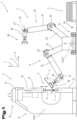
- a bending system 1 is shown with a manipulation system 2 shown in simplified form.
- the bending system 1 is designed in particular for the free bending of workpieces 3 to be manufactured from sheet metal by means of die bending, which can also be referred to as a production system.
- a metallic material is usually used as the starting material, which in its non-deformed state can be referred to as a flat material or flat element.
- Some system components of the bending system 1 are not shown or are only shown in a stylized way for the sake of clarity.
- the bending system 1 used for bending in the present case comprises at least one bending machine 4, in the present exemplary embodiment a bending press, in particular a press brake or press brake, for the production of the workpieces 3 or workpieces between at least one bending tool 5 that can be adjusted relative to one another.
- a bending press in particular a press brake or press brake
- only one bending machine was used 4, several of which can also be provided.
- the bending machine 4 is designed, among other things, for clamping the workpieces 3 or workpieces to be produced from the sheet metal between a clamping tool that can be adjusted relative to one another.
- the clamping tool then comprises at least a lower jaw and a cooperating upper jaw.
- the lower clamping jaw can also be referred to as the lower cheek or counter holder and the upper clamping jaw can also be referred to as the upper cheek or hold-down device.
- the lower clamping jaw can also be designed as a single punch.
- the bending machine 4 of the bending system 1 also includes a bending unit, which can also be referred to as a bending unit or forming unit. This training option for the bending machine 4 has only been described, but it is not shown in detail. The type and design of the bending machine 4 is not of essential importance in the process sequence described below. The main focus is more on the design of the manipulation system 2.
- the bending tool 5 of the bending machine 4 shown here and designed as a bending press comprises at least one bending punch 6, but usually several bending punches 6, and at least one bending die 7, but usually several bending dies 7 interacting with it.
- the at least one bending punch 6 is above the Arranged to be manufactured workpiece 3 on the bending machine 4 and held there accordingly, in particular clamped.
- the at least one bending die 7 is also held on the bending machine 4, in particular held clamped to it.
- the coordinate system is basically referred to as the “X” direction, which runs in a horizontal plane and in normal alignment with respect to the longitudinal extent of the bending tool 5, in particular its bending punch 6 and bending die 7. This is therefore the direction which also corresponds to the supply direction or the removal direction.
- the "Y” direction is understood to mean the vertical direction, which thus runs in the vertical direction of the bending tool 5 and further in the normal direction with respect to the horizontal plane.
- the “Z” direction is understood to mean that direction which runs in the longitudinal direction or in the longitudinal extension of the bending tool 5, in particular its bending punch 6 and bending die 7. The longitudinal extent of the bending edge or bending line defined by the bending tool 5 is thus also aligned in the “Z” direction.
- the bending machine 4 comprises a machine frame 8 which, for example, has a base plate 9 and side walls 10, 11 which project vertically therefrom and are spaced apart from one another in the transverse direction and aligned parallel to one another. These are preferred by one solid, for example formed from a sheet metal part cross brace 12 at their distanced from the bottom plate 9 end areas connected to each other.
- the side walls 10, 11 can be designed in an approximately C-shape to form a free space for the forming of the workpiece 3.
- the bending tool 5 is arranged and also held on press beams 13, 14.
- the lower press beam 13 is stationary and can also be referred to as a press table.
- the upper press beam 14 here is guided in linear guides 15 and can be adjusted relative to the lower press beam 13 in order to carry out the bending process.
- a drive arrangement 16 is provided for this purpose.
- a more detailed description and representation of a bending machine control unit, an input terminal and the energy supply have been omitted. Further details required for the operation of such a bending machine 4, such as feed devices or the like, are also omitted in the description of the subject in order to avoid an unnecessary length of the description.
- the manipulation system 2 comprises a first manipulator 17, at least one second manipulator 18 and a guide arrangement 19, on or on which the manipulators 17, 18 are adjustably guided along them.
- the adjustment movement can take place autonomously, it also being possible for drive energy and/or travel and/or adjustment commands to be transmitted from the guide arrangement 19 to the manipulators 17, 18.
- the guide arrangement 19 can, for example, comprise guide rails, guide rods or the like, which are preferably aligned to run in a straight line.
- the guide arrangement 19 defines a first axis 20 in the direction of its longitudinal extension.
- the guide arrangement 19 and thus also the first axis 20 preferably has a bending line or bending edge defined in a parallel direction with respect to a bending tool 5 or the clamping tool and is therefore also parallel with respect to the " aligned along the Z" axis of the coordinate system.
- manipulators 17, 18 The most important structural components of the manipulators 17, 18 are described below, the structural components of which are basically of the same design, but the arrangement on the manipulators 17, 18 can differ from one another. Those components of the first manipulator 17 are identified without inverted commas or without "'" and those of the second manipulator 18 are identified with inverted commas or with "'".
- Each of the manipulators 17, 18 comprises a base frame 21, 21' which is adjustably guided on the guide arrangement 19, e.g. by means of wheels and/or separate guide elements.
- the more detailed representation and description of drive means has been omitted, since this is well known and can be freely selected according to the known prior art.
- a first manipulator arm 22, 22' is mounted on the base frame 21, 21' so as to be pivotable about a second axis 23, 23'.
- a second manipulator arm 24, 24' is pivotably mounted about a third axis 25, 25' on each end region of the first manipulator arm 22, 22' that faces away from the base frame 21, 21'.
- a third manipulator arm 26, 26' is also provided, each of the third manipulator arms 26, 26' being pivotable about a fourth axis 27, 27' on a side facing away from the base frame 21, 21' on the respective second manipulator arm 24, 24' .
- the second axes 23, 23′, the third axes 25, 25′ and also the fourth axes 27, 27′ each and exclusively have a parallel alignment with respect to the first axis 20 .
- the axes mentioned above are also aligned parallel with respect to the bending line of the bending machine 4.
- the first manipulator arms 22, 22' can be arranged on the respective base frame 21, 21' either centrally on it or also on the side thereof, as is shown in the present exemplary embodiment.
- a holding arrangement 28, 28' is also arranged or provided on each of the third manipulator arms 26, 26'.
- the holding arrangement 28, 28' can, for example, be in the form of gripping tongs, a vacuum suction device, a holding magnet or the like.
- Each of the holding arrangements 28, 28' is mounted on the respective third manipulator arm 26, 26' such that it can be rotated about a fifth axis 29, 29'.
- Each of the fifth axes 29, 29' has a normal orientation with respect to the respective fourth axis 27, 27' and is thus oriented at right angles thereto. This possibility of rotation or pivoting allows the metal sheet or workpiece 3 held on the holding arrangement 28, 28' to be rotated, for example, about its own axis.
- each of the manipulators 17, 18 that each of the third manipulator arms 26, 26' is arranged on the side facing away from the first manipulator arm 22, 22' on the second manipulator arm 24, 24'.
- the manipulators 17, 18 are arranged one behind the other on or on the common guide arrangement 19 and can be displaced along this relative thereto. Furthermore, the individual manipulator arms are arranged as mirror images of one another, with this taking place with respect to a fictitious normal plane between the two manipulators 17 , 18 to the first axis 20 .
- the third manipulator arm 26 of the first manipulator 17 is thus arranged on that side of the second manipulator arm 24 which faces the second manipulator 18 .
- the same also applies to the third manipulator arm 26' of the second manipulator 18.
- the third manipulator arm 26' of the second manipulator 18 is thus arranged on that side of the second manipulator arm 24' which faces the first manipulator 17.
- the second manipulator arm 24 of the first manipulator 17 is arranged on that side of its first manipulator arm 22 which faces the second manipulator 18 .
- the second manipulator arm 24' of the second manipulator 18 is also arranged on that side of its first manipulator arm 22' which faces the first manipulator 17. This means that each of the third manipulator arms 26, 26' is not on the same side as the first manipulator arms 22, 22'. There is always an arrangement in the direction of the opposite manipulator 18 or 17.
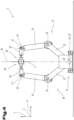
- the fifth axis 29 of the first manipulator 17 is arranged to run in a first normal plane 30 with respect to the first axis 20 . Provision is also made for the first normal plane 30 to be arranged at a distance from the base frame 21 of the first manipulator 17 in the direction of the first axis 20 and in the direction of the second manipulator 18 by a first distance 31 .
- the fifth axis 29 of the second manipulator 18 is arranged to run in a second normal plane 32 with respect to the first axis 20 . Furthermore, the second normal plane 32 is spaced apart by a second distance 33 from the base frame 21 ′ of the second manipulator 18 in the direction of the first axis 20 and in the direction of the first manipulator 17 .
- the manipulators 17, 18 In order to enable the two holding arrangements 28, 28' to be arranged opposite one another for the transfer process, at least one of the manipulators 17, 18 must be shifted in the direction of the other of the manipulators 18, 17. Due to the manipulators 17, 18 on the outside with respect to the base frame 21, 21' and located opposite The position of the third manipulator arms 26, 26 ⁇ , the manipulators 17, 18 can be arranged directly adjacent to one another.
- a sum of the first distance 31 plus the second distance 33 corresponds to at least one largest dimension of one of the third manipulator arms 26, 26 ⁇ in the direction of the first axis 20.
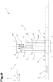
- the position of the manipulators 17, 18 and the manipulator arms before and during the transfer process is best from the Figures 2 to 4 to see. If, for example, a workpiece 3 or sheet metal is gripped by the holding arrangement 28 of the first manipulator 17 and this is to be transferred directly and without intermediate storage to the holding arrangement 28 ⁇ of the second manipulator 18, the third manipulator arms 26, 26 ⁇ must be aligned opposite one another and protruding towards one another .
- the holding arrangement 28 ⁇ of the second manipulator 18 can then likewise grasp the same workpiece 3 or sheet metal.
- the holding arrangement 28 of the first manipulator 17 is usually grasped or held on a first side and the holding arrangement 28 ⁇ of the second manipulator 18 is grasped or held on the opposite second side.
- the workpiece 3 or sheet metal can be released from the holding arrangement 28 of the first manipulator 17.
- a transfer from the holding arrangement 28' of the second manipulator 18 to the holding arrangement 28 of the first manipulator 17 takes place in the same way.
- the fifth axes 29, 29' of the third manipulator arms 26, 26' can preferably be arranged in a parallel alignment to one another for the transfer process. It can also be advantageous if the fifth axes 29, 29' of the third manipulator arms 26, 26' are arranged in alignment with one another for the transfer process.
- the first manipulator arm 22 and the second manipulator arm 24 of the first manipulator 17 are arranged on a first side with respect to a vertical center plane 34 of the guide arrangement 19 running in the direction of the first axis 20 .
- the first manipulator arm 22' and the second manipulator arm 24' of the second manipulator 18, on the other hand, can be or will be arranged on a second side, opposite the first side, of the center plane 34 of the guide arrangement 19.
- All information on value ranges in the present description is to be understood in such a way that it also includes any and all sub-ranges, e.g. the information 1 to 10 is to be understood in such a way that all sub-ranges, starting from the lower limit 1 and the upper limit 10, are also included , i.e. all subranges start with a lower limit of 1 or greater and end with an upper limit of 10 or less, e.g. 1 to 1.7, or 3.2 to 8.1, or 5.5 to 10.
- first distance 2 manipulation system 32 second normal level 3 workpiece 33 second distance 4 bending machine 34 midplane 5 bending tool 6 bending stamp 7 bending die 8th machine frame 9 bottom plate 10 sidewall 11 sidewall 12 cross-dressing 13 press bar 14 press bar 15 linear guide 16 drive assembly 17 first manipulator 18 second manipulator 19 guide arrangement 20 first axis 21 base frame 22 first manipulator arm 23 second axis 24 second manipulator arm 25 third axis 26 third manipulator arm 27 fourth axis 28 holding arrangement 29 fifth axis 30 first normal level
Landscapes
- Engineering & Computer Science (AREA)
- Mechanical Engineering (AREA)
- Robotics (AREA)
- Manipulator (AREA)
- Bending Of Plates, Rods, And Pipes (AREA)
Description
Die Erfindung betrifft ein Übergabeverfahren zur direkten Übergabe von zumindest einem zu biegenden Blech oder einem aus dem Blech umgeformten Werkstück bei einer Biegeanlage mit zumindest einer Biegemaschine mittels eines Manipulationssystems von einem ersten Manipulator zu zumindest einem zweiten Manipulator, ein dazu ausgebildetes Manipulationssystem sowie eine Biegeanlage mit einem derartigen Manipulationssystem.The invention relates to a transfer method for the direct transfer of at least one metal sheet to be bent or a workpiece formed from the metal sheet in a bending system with at least one bending machine by means of a manipulation system from a first manipulator to at least a second manipulator, a manipulation system designed for this purpose and a bending system with a such manipulation system.
Die
Die
Es beschreibt die
Die
Die
Aus der
Bei den bislang eingesetzten Manipulatoren mit vier parallel zueinander verlaufenden Achsen und einer dazu in normaler Ausrichtung verlaufenden, fünften Handhabungsachse war keine direkte Übergabe zwischen zwei nebeneinander befindlichen Manipulatoren ohne dem Schritt einer Zwischenablage des zu übergebenden Blechs oder Werkstücks möglich.With the previously used manipulators with four axes running parallel to one another and a fifth handling axis running in normal alignment with them, no direct transfer between two manipulators located next to one another was possible without the step of intermediate storage of the sheet metal or workpiece to be transferred.
Aufgabe der vorliegenden Erfindung war es, die Nachteile des Standes der Technik zu überwinden ein Übergabeverfahren, ein Manipulationssystem und eine ein derartiges Manipulationssystem umfassende Biegeanlage und zur Verfügung zu stellen, mittels derer ein noch rascherer und sicherer Übergabevorgang zwischen zwei zusammenwirkenden Manipulatoren durchführbar ist.The object of the present invention was to overcome the disadvantages of the prior art and to provide a transfer method, a manipulation system and a bending system comprising such a manipulation system, by means of which an even faster and safer transfer process between two interacting manipulators can be carried out.
Diese Aufgabe wird durch ein Verfahren zur Übergabe, ein Manipulationssystem und eine ein derartiges Manipulationssystem umfassende Biegeanlage gemäß den Ansprüchen gelöst.This object is achieved by a method for transfer, a manipulation system and a bending system comprising such a manipulation system according to the claims.
Eine Aufgabe der Erfindung wird durch das Übergabeverfahren gelöst, bei welchem eine direkte Übergabe von zumindest einem zu biegenden Blech oder einem aus dem Blech umgeformten Werkstück bei einer Biegeanlage mit zumindest einer Biegemaschine mittels eines Manipulationssystems von einem ersten Manipulator zu zumindest einem zweiten Manipulator erfolgt und bei dem folgende Schritte ausgeführt werden:
- Bereitstellen einer gemeinsamen Führungsanordnung, welche gemeinsame Führungsanordnung in Richtung ihrer Längserstreckung eine gemeinsame erste Achse für jeden der Manipulatoren definiert und jeder Manipulator entlang der gemeinsamen Führungsanordnung in Richtung der erste Achse autonom verfahrbar ist,
- Bereitstellen des ersten Manipulators und zumindest des zweiten Manipulators, jeder der Manipulatoren umfasst
- ein Basisgestell,
- einen ersten Manipulatorarm, wobei jeder der ersten Manipulatorarme am jeweiligen Basisgestell um eine zweite Achse verschwenkbar ist,
- einen zweiten Manipulatorarm, wobei jeder der zweiten Manipulatorarme an einer vom Basisgestell abgewendeten Seite am jeweiligen ersten Manipulatorarm um eine dritte Achse verschwenkbar ist,
- einen dritten Manipulatorarm, wobei jeder der dritten Manipulatorarme an einer vom Basisgestell abgewendeten Seite am jeweiligen zweiten Manipulatorarm um eine vierte Achse verschwenkbar ist,
- wobei die zweiten Achsen, die dritten Achsen und auch die vierten Achsen jeweils ausschließlich eine parallele Ausrichtung bezüglich der ersten Achse aufweisen,
- eine Halteanordnung, welche Halteanordnung am jeweiligen dritten Manipulatorarm angeordnet oder ausgebildet ist und jede der Halteanordnungen um eine fünfte Achse verdrehbar ist, wobei jede der fünften Achsen eine normale Ausrichtung bezüglich der jeweiligen vierten Achse aufweist,
- wobei jeder der dritten Manipulatorarme jeweils auf der vom ersten Manipulatorarm abgewendeten Seite am zweiten Manipulatorarm angeordnet ist,
- wobei ein Blech oder ein Werkstück an seiner ersten Seite mit der Halteanordnung des ersten Manipulators erfasst oder ergriffen wird, und
- wobei die Manipulatoren in Richtung der ersten Achse an oder auf der gemeinsamen Führungsanordnung hintereinander und in einer relativen Stellung zueinander angeordnet werden, in welcher der dritte Manipulatorarm des ersten Manipulators auf jener Seite des zweiten Manipulatorarms angeordnet ist, welche dem zweiten Manipulator zugewendet ist und der dritte Manipulatorarm des zweiten Manipulators auf jener Seite des zweiten Manipulatorarms angeordnet ist, welche dem ersten Manipulator zugewendet ist, wobei weiters noch vorgesehen ist,
- dass die Manipulatoren für den Übergabevorgang unmittelbar benachbart zueinander angeordnet werden, und dabei zumindest einer der Manipulatoren in Richtung auf den anderen Manipulator verlagert wird und weiters dabei die dritten Manipulatorarme (26, 26' einander gegenüberliegend sowie deren fünften Achsen jeweils aufeinander zu ragend ausgerichtet werden,
- dass für den Übergabevorgang der erste und der zweite Manipulatorarm des ersten Manipulators auf einer ersten Seite bezüglich einer in Richtung der ersten Achse verlaufend ausgerichteten vertikalen Mittelebene der Führungsanordnung und der erste und zweite Manipulatorarm des zweiten Manipulators auf einer der ersten Seite gegenüberliegenden zweiten Seite der Mittelebene der Führungsanordnung angeordnet werden, wobei die vertikale Mittelebene in einer normalen Richtung bezüglich einer Horizontalebene verläuft, und
- dass das selbe Blech oder Werkstück an seiner der ersten Seite gegenüberliegenden zweiten Seite mit der Halteanordnung des zweiten Manipulators erfasst oder ergriffen wird und das Blech oder das Werkstück von der Halteanordnung des ersten Manipulators freigegeben oder losgelassen wird.
- Providing a common guide arrangement, which common guide arrangement defines a common first axis for each of the manipulators in the direction of its longitudinal extent, and each manipulator can be moved autonomously along the common guide arrangement in the direction of the first axis,
- providing the first manipulator and at least the second manipulator, each of which includes manipulators
- a base frame,
- a first manipulator arm, each of the first manipulator arms being pivotable about a second axis on the respective base frame,
- a second manipulator arm, each of the second manipulator arms being pivotable about a third axis on a side facing away from the base frame on the respective first manipulator arm,
- a third manipulator arm, each of the third manipulator arms being pivotable about a fourth axis on a side facing away from the base frame on the respective second manipulator arm,
- wherein the second axes, the third axes and also the fourth axes each exclusively have a parallel alignment with respect to the first axis,
- a holding arrangement, which holding arrangement is arranged or formed on the respective third manipulator arm and each of the holding arrangements can be rotated about a fifth axis, each of the fifth axes having a normal alignment with respect to the respective fourth axis,
- wherein each of the third manipulator arms is arranged on the side facing away from the first manipulator arm on the second manipulator arm,
- wherein a sheet metal or a workpiece is grasped or grasped on its first side with the holding arrangement of the first manipulator, and
- wherein the manipulators are arranged one behind the other in the direction of the first axis at or on the common guide arrangement and in a relative position to one another, in which the third manipulator arm of the first manipulator is on that side of the second manipulator arm is arranged, which faces the second manipulator and the third manipulator arm of the second manipulator is arranged on that side of the second manipulator arm which faces the first manipulator, it also being provided
- that the manipulators for the transfer process are arranged directly adjacent to one another, and at the same time at least one of the manipulators is shifted in the direction of the other manipulator and, moreover, the third manipulator arms (26, 26' are aligned opposite one another and their fifth axes each projecting towards one another,
- that for the transfer process the first and the second manipulator arm of the first manipulator on a first side with respect to a vertical center plane of the guide arrangement running in the direction of the first axis and the first and second manipulator arm of the second manipulator on a second side of the center plane of the guiding arrangement are arranged with the vertical median plane extending in a normal direction with respect to a horizontal plane, and
- that the same sheet metal or workpiece is grasped or gripped on its second side opposite the first side with the holding arrangement of the second manipulator and the sheet metal or the workpiece is released or released from the holding arrangement of the first manipulator.
Vorteilhaft ist bei diesen Verfahrensschritten, dass damit durch die spiegelsymmetrische Anordnung der einzelnen Manipulatorarme des ersten Manipulators bezüglich des zweiten Manipulators die Möglichkeit geschaffen wird, die Manipulatoren für die direkte Übergabe zwischen deren Halteanordnungen soweit in deren Verstellrichtung nebeneinander angeordnet werden, dass deren Halteanordnungen einander gegenüberliegend sowie aufeinander zu ragend angeordnet sind. Damit wird bei derartig einfach ausgebildeten Manipulatoren, bei welchen die Schwenkachsen der einzelnen Manipulatorarme eine parallele Ausrichtung bezüglich der von der Führungsanordnung definierten Achse aufweisen, trotzdem die direkte Übergabe von Werkstücken zwischen den Halteanordnungen der Manipulatoren ohne des Zwischenschritts einer Zwischenablage ermöglich. So werden ausreichende Platzverhältnisse geschaffen und es werden somit Kollisionen zwischen den einzelnen Manipulatoren und deren Manipulatorarme beim Übergabevorgang verhindert. Bei Manipulatoren, bei welchen der unmittelbar dem Basisgehäuse zugewendete erste Manipulatorarm auch noch um eine vertikale Drehachse verdrehbar ist, wäre die direkte Übergabe durch ein aufeinander Zudrehen bzw. Zuwenden der Halteanordnungen realisierbar, wobei diese zusätzliche Verdrehbewegung bei den erfindungsgemäßen Manipulatoren mit den stets in paralleler Richtung zur Verstellachse der Führungsanordnung ausgerichteten Schwenkachsen der Manipulatorarme nicht vorgesehen ist.The advantage of these method steps is that the mirror-symmetrical arrangement of the individual manipulator arms of the first manipulator with respect to the second manipulator creates the possibility of arranging the manipulators next to one another in their adjustment direction for direct transfer between their holding arrangements so that their holding arrangements are opposite one another and are arranged to project towards each other. With such simply designed manipulators, in which the pivot axes of the individual manipulator arms have a parallel alignment with respect to the axis defined by the guide arrangement, the direct transfer of workpieces between the holding arrangements of the manipulators is still possible without the intermediate step of a clipboard. Sufficient space is thus created and collisions between the individual manipulators and their manipulator arms are prevented prevented during the transfer process. In the case of manipulators in which the first manipulator arm directly facing the base housing can also be rotated about a vertical axis of rotation, the direct transfer could be realized by rotating or turning the holding arrangements towards one another, with this additional rotating movement in the manipulators according to the invention with the always in a parallel direction pivot axes of the manipulator arms aligned with the adjustment axis of the guide arrangement is not provided.
Sind für den Übergabevorgang der erste und der zweite Manipulatorarm des ersten Manipulators auf einer ersten Seite bezüglich einer in Richtung der ersten Achse verlaufend ausgerichteten vertikalen Mittelebene der Führungsanordnung und der erste und zweite Manipulatorarm des zweiten Manipulators auf einer der ersten Seite gegenüberliegenden zweiten Seite der Mittelebene der Führungsanordnung angeordnet, wird dadurch auf kürzestem Wege eine Stellung der einzelnen Manipulatorarme des ersten und zweiten Manipulators zueinander erzielt. Damit befinden sich auf jeder Seite der Mittelebene die jeweiligen Manipulatorarme des ersten Manipulators sowie des zweiten Manipulators, wodurch eine noch einfachere einander gegenüberliegende Anordnung der Halteanordnungen erzielbar ist.If, for the transfer process, the first and the second manipulator arm of the first manipulator are on a first side with respect to a vertical center plane of the guide arrangement running in the direction of the first axis, and the first and second manipulator arm of the second manipulator are on a second side, opposite the first side, of the center plane of the Arranged guide arrangement, a position of the individual manipulator arms of the first and second manipulator is thereby achieved in the shortest possible way to each other. The respective manipulator arms of the first manipulator and of the second manipulator are thus located on each side of the central plane, as a result of which an even simpler mutually opposite arrangement of the holding arrangements can be achieved.
Weiters ist ein Vorgehen vorteilhaft, bei dem der zweite Manipulatorarm des ersten Manipulators auf jener Seite des ersten Manipulatorarms angeordnet ist, welche dem zweiten Manipulator zugewendet ist. Damit können unnötige Kollisionen zwischen den Basisgestellen der Manipulatoren verhindert werden.Furthermore, a procedure is advantageous in which the second manipulator arm of the first manipulator is arranged on that side of the first manipulator arm which faces the second manipulator. This can prevent unnecessary collisions between the base frames of the manipulators.
Eine weitere vorteilhafte Vorgehensweise ist dadurch gekennzeichnet, wenn der zweite Manipulatorarm des zweiten Manipulators auf jener Seite des ersten Manipulatorarms angeordnet ist, welche dem ersten Manipulator zugewendet ist. Damit kann eine zusätzliche Distanzierung der beiden Basisgestelle der Manipulatoren im Zuge des Übergabevorgangs erzielt werden.A further advantageous procedure is characterized in that the second manipulator arm of the second manipulator is arranged on that side of the first manipulator arm which faces the first manipulator. In this way, an additional distance between the two base frames of the manipulators can be achieved during the transfer process.
Vorteilhaft ist auch eine Verfahrensvariante, bei welcher für den Übergabevorgang jeweils die fünften Achsen der dritten Manipulatorarme in paralleler Ausrichtung zueinander angeordnet werden. Durch das parallele Ausrichten der Übergabevorrichtungen zueinander kann ein sicherer Übergabevorgang zwischen den beiden Halteanordnungen erzielt werden.A variant of the method is also advantageous in which the fifth axes of the third manipulator arms are arranged in parallel alignment with one another for the transfer process. By aligning the transfer devices parallel to one another, a safe transfer process between the two holding arrangements can be achieved.
Eine andere Vorgehensweise zeichnet sich dadurch aus, wenn für den Übergabevorgang jeweils die fünften Achsen der dritten Manipulatorarme in fluchtender Ausrichtung zueinander angeordnet werden. Durch das fluchtende Ausrichten der fünften Achsen der einander zugewendeten Übergabeanordnungen kann so auch bei der übernehmenden Halteanordnung ebenfalls ein sicheres Halten und Ergreifen ermöglicht werden.Another procedure is distinguished by the fifth axis of the third manipulator arm being arranged in alignment with one another for the transfer process. By aligning the fifth axes of the mutually facing transfer arrangements, safe holding and gripping can also be made possible in the receiving holding arrangement.
Eine weitere vorteilhafte Vorgehensweise ist dadurch gekennzeichnet, dass die erste Achse der Führungsanordnung in paralleler Ausrichtung bezüglich einer von einer Biegemaschine der Biegeanlage definierten Biegelinie ausgerichtet ist. Damit kann stets ohne zusätzliche Querverstellung bezüglich der ersten Achse ein gleicher Abstand des zu transportierenden Werkstücks bzw. Blechs bezüglich der Biegelinie eingehalten werden.A further advantageous procedure is characterized in that the first axis of the guide arrangement is aligned in parallel with respect to a bending line defined by a bending machine of the bending system. In this way, the same distance between the workpiece or metal sheet to be transported and the bending line can always be maintained without additional transverse adjustment with respect to the first axis.
Die Aufgabe der Erfindung wird aber eigenständig auch durch ein Manipulationssystem für eine Biegeanlage umfassend zumindest eine Biegemaschine gelöst. Das Manipulationssystem dient zur direkten Übergabe von zumindest einem zu biegenden Blech oder einem aus dem Blech umgeformten Werkstück von einem ersten Manipulator zu zumindest einem zweiten Manipulator. Das Manipulationssystem umfasst
- eine gemeinsame Führungsanordnung, welche gemeinsame Führungsanordnung in Richtung ihrer Längserstreckung eine gemeinsame erste Achse für jeden der Manipulatoren definiert und jeder Manipulator des Manipulationssystems entlang der gemeinsamen Führungsanordnung in Richtung der erste Achse autonom verfahrbar ist,
- der erste Manipulator und der zumindest eine zweiter Manipulator umfassen j e-weils
- ein Basisgestell,
- einen ersten Manipulatorarm, wobei jeder der ersten Manipulatorarme am jeweiligen Basisgestell um eine zweite Achse verschwenkbar ist,
- einen zweiten Manipulatorarm, wobei jeder der zweiten Manipulatorarme an einer vom Basisgestell abgewendeten Seite am jeweiligen ersten Manipulatorarm um eine dritte Achse verschwenkbar ist,
- einen dritten Manipulatorarm, wobei jeder der dritten Manipulatorarme an einer vom Basisgestell abgewendeten Seite am jeweiligen zweiten Manipulatorarm um eine vierte Achse verschwenkbar ist,
- wobei die zweiten Achsen, die dritten Achsen und auch die vierten Achsen jedes Manipulators jeweils ausschließlich eine parallele Ausrichtung bezüglich der ersten Achse aufweisen,
- eine Halteanordnung, welche Halteanordnung am jeweiligen dritten Manipulatorarm angeordnet oder ausgebildet ist und jede der Halteanordnungen um eine fünfte Achse verdrehbar ist, wobei jede der fünften Achsen eine normale Ausrichtung bezüglich der jeweiligen vierten Achse aufweist, wobei
- jeder der dritten Manipulatorarme jeweils auf der vom ersten Manipulatorarm abgewendeten Seite am zweiten Manipulatorarm angeordnet ist, und wobei
- der erste Manipulator und der zumindest eine zweite Manipulator in Richtung der ersten Achse hintereinander an oder auf der gemeinsamen Führungsanordnung angeordnet sind,
- wobei der dritte Manipulatorarm des ersten Manipulators auf jener Seite des zweiten Manipulatorarms angeordnet ist, welche dem zweiten Manipulator zugewendet ist, und
- wobei der dritte Manipulatorarm des zweiten Manipulators auf jener Seite des zweiten Manipulatorarms angeordnet ist, welche dem ersten Manipulator zugewendet ist, wobei weiters vorgesehen ist
- dass die Manipulatoren für den Übergabevorgang unmittelbar benachbart zueinander angeordnet sind, und dabei die dritten Manipulatorarme einander gegenüberliegend sowie deren fünfte Achsen (29, 29') jeweils aufeinander zu ragend ausgerichtet sind, und
- dass für den Übergabevorgang der erste und der zweite Manipulatorarm des ersten Manipulators auf einer ersten Seite bezüglich einer in Richtung der ersten Achse verlaufend ausgerichteten vertikalen Mittelebene der Führungsanordnung und der erste und zweite Manipulatorarm des zweiten Manipulators auf einer der ersten Seite gegenüberliegenden zweiten Seite der Mittelebene der Führungsanordnung angeordnet sind, wobei die vertikale Mittelebene in einer normalen Richtung bezüglich einer Horizontalebene verläuft.
- a common guide arrangement, which common guide arrangement defines a common first axis for each of the manipulators in the direction of its longitudinal extent, and each manipulator of the manipulation system can be moved autonomously along the common guide arrangement in the direction of the first axis,
- the first manipulator and the at least one second manipulator each comprise e-weils
- a base frame,
- a first manipulator arm, each of the first manipulator arms being pivotable about a second axis on the respective base frame,
- a second manipulator arm, each of the second manipulator arms being pivotable about a third axis on a side facing away from the base frame on the respective first manipulator arm,
- a third manipulator arm, each of the third manipulator arms being pivotable about a fourth axis on a side facing away from the base frame on the respective second manipulator arm,
- the second axes, the third axes and also the fourth axes of each manipulator each exclusively having a parallel orientation with respect to the first have an axis
- a holding arrangement, which holding arrangement is arranged or formed on the respective third manipulator arm and each of the holding arrangements can be rotated about a fifth axis, each of the fifth axes having a normal alignment with respect to the respective fourth axis, wherein
- each of the third manipulator arms is arranged on the side facing away from the first manipulator arm on the second manipulator arm, and wherein
- the first manipulator and the at least one second manipulator are arranged one behind the other in the direction of the first axis on or on the common guide arrangement,
- wherein the third manipulator arm of the first manipulator is arranged on that side of the second manipulator arm which faces the second manipulator, and
- wherein the third manipulator arm of the second manipulator is arranged on that side of the second manipulator arm which faces the first manipulator, the further provision being provided
- that the manipulators for the transfer process are arranged directly adjacent to one another, and the third manipulator arms are arranged opposite one another and their fifth axes (29, 29') are each aligned so as to project towards one another, and
- that for the transfer process the first and the second manipulator arm of the first manipulator on a first side with respect to a vertical center plane of the guide arrangement running in the direction of the first axis and the first and second manipulator arm of the second manipulator on a second side of the center plane of the Guide arrangement are arranged, wherein the vertical median plane is in a normal direction with respect to a horizontal plane.
Der dadurch erzielte Vorteil liegt darin, dass damit durch die spiegelsymmetrische Anordnung der einzelnen Manipulatorarme des ersten Manipulators bezüglich der Manipulatorarme des zweiten Manipulators die Möglichkeit geschaffen wird, die Manipulatoren für die direkte Übergabe zwischen deren Halteanordnungen soweit in deren Verstellrichtung nebeneinander angeordnet werden, dass deren Halteanordnungen einander gegenüberliegend sowie aufeinander zu ragend angeordnet sind. Damit wird bei derartig einfach ausgebildeten Manipulatoren, bei welchen die Schwenkachsen der einzelnen Manipulatorarme eine parallele Ausrichtung bezüglich der von der Führungsanordnung definierten Achse aufweisen, trotzdem die direkte Übergabe von Werkstücken zwischen den Halteanordnungen der Manipulatoren ohne des Zwischenschritts einer Zwischenablage ermöglich. So werden ausreichende Platzverhältnisse geschaffen und es werden somit Kollisionen zwischen den einzelnen Manipulatoren und deren Manipulatorarme beim Übergabevorgang verhindert. Bei Manipulatoren, bei welchen der unmittelbar dem Basisgehäuse zugewendete erste Manipulatorarm auch noch um eine vertikale Drehachse verdrehbar ist, wäre die direkte Übergabe durch ein aufeinander Zudrehen bzw. Zuwenden der Halteanordnungen realisierbar, wobei diese zusätzliche Verdrehbewegung bei den erfindungsgemäßen Manipulatoren mit den stets in paralleler Richtung zur Verstellachse der Führungsanordnung ausgerichteten Schwenkachsen der Manipulatorarme nicht vorgesehen ist.The advantage achieved in this way is that the mirror-symmetrical arrangement of the individual manipulator arms of the first manipulator with respect to the manipulator arms of the second manipulator creates the possibility of arranging the manipulators next to one another in their adjustment direction for the direct transfer between their holding arrangements to such an extent that their holding arrangements are arranged opposite one another and projecting towards one another. Thus, with manipulators of such a simple design, in which the pivot axes of the individual manipulator arms have a parallel alignment with respect to the axis defined by the guide arrangement, the direct Allowing the transfer of workpieces between the holding arrangements of the manipulators without the intermediate step of a clipboard. This creates sufficient space and thus prevents collisions between the individual manipulators and their manipulator arms during the transfer process. In the case of manipulators in which the first manipulator arm directly facing the base housing can also be rotated about a vertical axis of rotation, the direct transfer could be realized by rotating or turning the holding arrangements towards one another, with this additional rotating movement in the manipulators according to the invention with the always in a parallel direction pivot axes of the manipulator arms aligned with the adjustment axis of the guide arrangement is not provided.
Sind für den Übergabevorgang der erste und der zweite Manipulatorarm des ersten Manipulators auf einer ersten Seite bezüglich einer in Richtung der ersten Achse verlaufend ausgerichteten vertikalen Mittelebene der Führungsanordnung und der erste und zweite Manipulatorarm des zweiten Manipulators auf einer der ersten Seite gegenüberliegenden zweiten Seite der Mittelebene der Führungsanordnung angeordnet, wird dadurch auf kürzestem Wege eine Stellung der einzelnen Manipulatorarme des ersten und zweiten Manipulators zueinander erzielt. Damit befinden sich auf jeder Seite der Mittelebene die jeweiligen Manipulatorarme des ersten Manipulators sowie des zweiten Manipulators, wodurch eine noch einfachere einander gegenüberliegende Anordnung der Halteanordnungen erzielbar ist.If, for the transfer process, the first and the second manipulator arm of the first manipulator are on a first side with respect to a vertical center plane of the guide arrangement running in the direction of the first axis, and the first and second manipulator arm of the second manipulator are on a second side, opposite the first side, of the center plane of the Arranged guide arrangement, a position of the individual manipulator arms of the first and second manipulator is thereby achieved in the shortest possible way to each other. The respective manipulator arms of the first manipulator and of the second manipulator are thus located on each side of the central plane, as a result of which an even simpler mutually opposite arrangement of the holding arrangements can be achieved.
Weiters kann es vorteilhaft sein, wenn der zweite Manipulatorarm des ersten Manipulators auf jener Seite des ersten Manipulatorarms angeordnet ist, welche dem zweiten Manipulator zugewendet ist. Damit können unnötige Kollisionen zwischen den Basisgestellen der Manipulatoren verhindert werden.Furthermore, it can be advantageous if the second manipulator arm of the first manipulator is arranged on that side of the first manipulator arm which faces the second manipulator. This can prevent unnecessary collisions between the base frames of the manipulators.
Eine andere Ausführungsform zeichnet sich dadurch aus, dass der zweite Manipulatorarm des zweiten Manipulators auf jener Seite des ersten Manipulatorarms angeordnet ist, welche dem ersten Manipulator zugewendet ist. Damit kann eine zusätzliche Distanzierung der beiden Basisgestelle der Manipulatoren im Zuge des Übergabevorgangs erzielt werden.Another embodiment is characterized in that the second manipulator arm of the second manipulator is arranged on that side of the first manipulator arm which faces the first manipulator. In this way, an additional distance between the two base frames of the manipulators can be achieved during the transfer process.
Eine weitere mögliche Ausführungsform hat die Merkmale, dass die fünfte Achse des ersten Manipulators in einer ersten Normalebene bezüglich der ersten Achse verlaufend angeordnet ist und die erste Normalebene vom Basisgestell des ersten Manipulators in Richtung der erst en Achse sowie in Richtung auf den zweiten Manipulator um einen ersten Abstand beabstandet angeordnet ist. Dadurch kann ausreichend Platz zwischen der fünften Achse der Halteanordnung und der randseitigen Begrenzung des Basisgestells geschaffen werden. Damit kann auch im Bereich des zweiten Manipulators eine Beabstandung bzw. Distanzierung der fünften Achse vom umfänglichen Randbereich des Basisgestells erzielt werden.Another possible embodiment has the features that the fifth axis of the first manipulator is arranged to run in a first normal plane with respect to the first axis and the first normal plane from the base frame of the first manipulator in the direction of the first en axis and spaced in the direction of the second manipulator by a first distance. As a result, sufficient space can be created between the fifth axis of the holding arrangement and the boundary of the base frame at the edge. In this way, the fifth axis can also be spaced or distanced from the peripheral edge area of the base frame in the area of the second manipulator.
Eine weitere Ausbildung sieht vor, dass die fünfte Achse des zweiten Manipulators in einer zweiten Normalebene bezüglich der ersten Achse verlaufend angeordnet ist und die zweite Normalebene vom Basisgestell des zweiten Manipulators in Richtung der ersten Achse sowie in Richtung auf den ersten Manipulator um einen zweiten Abstand beabstandet angeordnet ist. Damit können die beiden Manipulatoren im Bereich von deren Halteanordnungen kollisionsfrei aufeinander zu verstellt werden und trotzdem die Halteanordnungen einander gegenüberliegend für den Übergabevorgang positioniert werden.A further embodiment provides that the fifth axis of the second manipulator is arranged running in a second normal plane with respect to the first axis and the second normal plane is spaced a second distance from the base frame of the second manipulator in the direction of the first axis and in the direction of the first manipulator is arranged. In this way, the two manipulators can be adjusted towards one another in the area of their holding arrangements without collision, and the holding arrangements can nevertheless be positioned opposite one another for the transfer process.
Eine andere Ausführungsform zeichnet sich dadurch aus, dass eine Summe des ersten Abstands zuzüglich des zweiten Abstands zumindest einer größten Abmessung eines der dritten Manipulatorarme in Richtung der ersten Achse entspricht. Durch diese Abmessungswahl kann ein sicheres und kollisionsfreies einander gegenüberliegendes Anordnen der beiden Manipulatorarme erzielt werden.Another embodiment is characterized in that a sum of the first distance plus the second distance corresponds to at least one largest dimension of one of the third manipulator arms in the direction of the first axis. This choice of dimensions allows the two manipulator arms to be arranged opposite one another in a safe and collision-free manner.
Die Aufgabe der Erfindung wird aber eigenständig auch durch eine Biegeanlage umfassend zumindest eine Biegemaschine und ein erfindungsgemäß ausgebildetes Manipulationssystem zur direkten Übergabe von zumindest einem zu biegenden Blech oder einem aus dem Blech umgeformten Werkstück von einem ersten Manipulator zu zumindest einem zweiten Manipulator gelöst.However, the object of the invention is also achieved independently by a bending system comprising at least one bending machine and a manipulation system designed according to the invention for the direct transfer of at least one sheet metal to be bent or a workpiece formed from the sheet metal from a first manipulator to at least one second manipulator.
Der dadurch erzielte Vorteil liegt darin, dass damit eine Biegeanlage geschaffen wird, bei welcher mittels des Manipulationssystems eine direkte Übergabe von Werkstücken zwischen den Manipulatoren ohne zusätzlichen Zwischenablageschritt ermöglicht wird. Damit wird die produktive Biegezeit der Biegemaschine erhöht, da zusätzliche Zwischenablagevorgänge nicht mehr erforderlich sind.The advantage achieved in this way is that a bending system is created in which the manipulation system enables workpieces to be transferred directly between the manipulators without an additional intermediate storage step. This increases the productive bending time of the bending machine, since additional intermediate storage processes are no longer required.
Zum besseren Verständnis der Erfindung wird diese anhand der nachfolgenden Figuren näher erläutert.For a better understanding of the invention, it is explained in more detail with reference to the following figures.
Es zeigen jeweils in stark vereinfachter, schematischer Darstellung:
- Fig. 1
- eine Biegeanlage mit einem Manipulationssystem zur direkten Übergabe eines Werkstücks oder Blechs von einem ersten Manipulator zu einem zweiten Manipulator, in Seitenansicht;
- Fig. 2
- die Manipulatoren des Manipulationssystems nach
Fig. 1 , in einer in Richtung der ersten Achse voneinander beabstandeten Stellung, in Ansicht; - Fig. 3
- die Manipulatoren des Manipulationssystems in deren Übergabestellung zueinander, in Ansicht;
- Fig. 4
- die Manipulatoren des Manipulationssystems in deren Übergabestellung zueinander, in Seitenansicht.
- 1
- a bending system with a manipulation system for the direct transfer of a workpiece or sheet metal from a first manipulator to a second manipulator, in side view;
- 2
- the manipulators of the manipulation system
1 12, in a spaced apart position in the direction of the first axis, in elevation; - 3
- the manipulators of the manipulation system in their transfer position to each other, in view;
- 4
- the manipulators of the manipulation system in their transfer position to each other, in side view.
Einführend sei festgehalten, dass in den unterschiedlich beschriebenen Ausführungsformen gleiche Teile mit gleichen Bezugszeichen bzw. gleichen Bauteilbezeichnungen versehen werden, wobei die in der gesamten Beschreibung enthaltenen Offenbarungen sinngemäß auf gleiche Teile mit gleichen Bezugszeichen bzw. gleichen Bauteilbezeichnungen übertragen werden können. Auch sind die in der Beschreibung gewählten Lageangaben, wie z.B. oben, unten, seitlich usw. auf die unmittelbar beschriebene sowie dargestellte Figur bezogen und sind diese Lageangaben bei einer Lageänderung sinngemäß auf die neue Lage zu übertragen.As an introduction, it should be noted that in the differently described embodiments, the same parts are provided with the same reference numbers or the same component designations, it being possible for the disclosures contained throughout the description to be applied to the same parts with the same reference numbers or the same component designations. The position information selected in the description, such as top, bottom, side, etc., is related to the figure directly described and shown and these position information are to be transferred to the new position in the event of a change of position.
Der Begriff "insbesondere" wird nachfolgend so verstanden, dass es sich dabei um eine mögliche speziellere Ausbildung oder nähere Spezifizierung eines Gegenstands oder eines Verfahrensschritts handeln kann, aber nicht unbedingt eine zwingende, bevorzugte Ausführungsform desselben oder eine zwingende Vorgehensweise darstellen muss.The term "in particular" is understood below to mean that it can be a possible more specific design or more detailed specification of an object or a method step, but does not necessarily have to represent a mandatory, preferred embodiment of the same or a mandatory procedure.
In den
Die im vorliegenden Fall für das Biegen eingesetzte Biegeanlage 1 umfasst zumindest eine Biegemaschine 4, im vorliegenden Ausführungsbeispiel eine Biegepresse, insbesondere eine Abkantpresse oder Gesenkbiegepresse, zur Herstellung der Werkstücke 3 oder Werkteile zwischen zumindest einem relativ zueinander verstellbaren Biegewerkzeug 5. Der Einfachheit wurde nur eine Biegemaschine 4 dargestellt, wobei auch mehrere derselben vorgesehen sein können.The bending system 1 used for bending in the present case comprises at least one bending machine 4, in the present exemplary embodiment a bending press, in particular a press brake or press brake, for the production of the
Es wäre aber auch unabhängig davon möglich, die Biegemaschine 4 als sogenannte Schwenkbiegemaschine oder Schwingbiegemaschine auszubilden. In diesem Fall kann die Biegeanlage 1 auch als Schwenkbiegeanlage oder Schwingbiegeanlage bezeichnet werden. Dabei umfasst Biegemaschine 4 eine Presse, die unter anderem zur klemmenden Halterung der aus dem Blech zu fertigenden Werkstücke 3 oder Werkteile zwischen einem relativ zueinander verstellbaren Klemmwerkzeug ausgebildet ist. Das Klemmwerkzeug umfasst dann zumindest eine untere Klemmbacke und eine damit zusammenwirkende obere Klemmbacke. Die untere Klemmbacke kann auch als Unterwange oder Gegenhalter und die obere Klemmbacke kann auch als Oberwange oder Niederhalter bezeichnet werden. Die untere Klemmbacke kann auch als einziger Stempel durchgängig ausgebildet sein. Zur Durchführung des Biegevorgangs umfasst die Biegemaschine 4 der Biegeanlage 1 auch noch eine Biegeeinheit, welche auch als Abkanteinheit oder Umformeinheit bezeichnet werden kann. Diese Ausbildungsmöglichkeit der Biegemaschine 4 ist nur beschrieben worden, jedoch ist diese nicht näher dargestellt. Die Art und Ausbildung der Biegemaschine 4 ist bei dem nachfolgend beschriebenen Verfahrensablauf nicht von wesentlicher Bedeutung. Das Hauptaugenmerk liegt eher auf der Ausbildung des Manipulationssystems 2.However, it would also be possible independently of this to design the bending machine 4 as a so-called swivel bending machine or oscillating bending machine. In this case, the bending system 1 can also be referred to as a swivel bending system or swing bending system. The bending machine 4 includes a press, which is designed, among other things, for clamping the
Das Biegewerkzeug 5 der hier gezeigten und als Biegepresse ausgebildeten Biegemaschine 4 umfasst im vorliegenden Ausführungsbeispiel zumindest einen Biegestempel 6, zumeist jedoch mehrere Biegestempel 6, und zumindest ein Biegegesenk 7, zumeist jedoch mehrere damit zusammenwirkende Biegegesenke 7. Der zumindest eine Biegestempel 6 ist dabei oberhalb des zu fertigenden Werkstücks 3 an der Biegemaschine 4 angeordnet und dort auch entsprechend gehalten, insbesondere geklemmt. Auch das zumindest eine Biegegesenk 7 ist an der Biegemaschine 4 gehalten, insbesondere daran geklemmt gehalten.In the present exemplary embodiment, the
Als Koordinatensystem wird bei derartigen Biegemaschinen 4 grundsätzliches als "X"-Richtung jene bezeichnet, welche in einer Horizontalebene sowie in normaler Ausrichtung bezüglich der Längserstreckung des Biegewerkzeugs 5, insbesondere dessen Biegestempel 6 sowie Biegegesenk 7 verläuft. Somit ist dies jene Richtung, welche auch der Zufuhrrichtung oder der Entnahmerichtung entspricht. Als "Y"-Richtung wird die Vertikalrichtung verstanden, welche somit in Höhenrichtung des Biegewerkzeugs 5 und weiters in normaler Richtung bezüglich der Horizontalebene verläuft. Schließlich wird als "Z"-Richtung jene Richtung verstanden, welche in Längsrichtung bzw. in der Längserstreckung des Biegewerkzeugs 5, insbesondere dessen Biegestempel 6 sowie Biegegesenk 7, verläuft. Damit ist auch die Längserstreckung der vom Biegewerkzeug 5 definierten Biegekante oder Biegelinie in der "Z"-Richtung verlaufend ausgerichtet.In such bending machines 4, the coordinate system is basically referred to as the “X” direction, which runs in a horizontal plane and in normal alignment with respect to the longitudinal extent of the
Die Biegemaschine 4 umfasst ein Maschinengestell 8, welches beispielsweise eine Bodenplatte 9 und vertikal davon aufragende und zueinander in Querrichtung beabstandet und parallel zueinander ausgerichtete Seitenwangen 10, 11 aufweist. Diese sind bevorzugt durch einen massiven, beispielsweise aus einem Blechformteil gebildeten Querverband 12 an ihren von der Bodenplatte 9 distanzierten Endbereichen miteinander verbunden.The bending machine 4 comprises a
Die Seitenwangen 10, 11 können zur Bildung eines Freiraums für das Umformen des Werkstücks 3 etwa C - förmig ausgebildet sein. Das Biegewerkzeug 5 ist an Pressbalken 13, 14 angeordnet und auch gehalten. Zumeist ist der untere Pressbalken 13 ortsfest angeordnet und kann auch als Presstisch bezeichnet werden. Der hier obere Pressbalken 14 ist in Linearführungen 15 geführt gelagert und ist relativ bezüglich des unteren Pressbalkens 13 zur Durchführung des Biegevorgangs relativ verstellbar. Dazu ist eine Antriebsanordnung 16 vorgesehen. Auf die nähere Beschreibung und Darstellung einer Biegemaschinen-Steuerungseinheit, eines Eingabeterminals sowie der Energieversorgung wurde der besseren Übersichtlichkeit halber verzichtet. Auf weitere für den Betrieb einer derartigen Biegemaschine 4 erforderliche Details, wie beispielsweise Zufuhrvorrichtungen oder dergleichen, wird in der gegenständlichen Beschreibung zur Vermeidung einer unnötigen Länge der Beschreibung ebenfalls verzichtet.The side walls 10, 11 can be designed in an approximately C-shape to form a free space for the forming of the
Das Manipulationssystem 2 umfasst einen ersten Manipulator 17, zumindest einen zweiten Manipulator 18 und eine Führungsanordnung 19, auf oder an welcher die Manipulatoren 17, 18 entlang dieser verstellbar geführt sind. Die Verstellbewegung kann autonom erfolgen, wobei auch eine Übertragung von Antriebsenergie und/oder Fahr- und/oder Verstellbefehlen von der Führungsanordnung 19 auf die Manipulatoren 17, 18 möglich ist. Die Führungsanordnung 19 kann z.B. Führungsschienen, Führungsstange oder dergleichen umfassen, welche bevorzugt geradlinig verlaufend ausgerichtet sind. Die Führungsanordnung 19 definiert in Richtung ihrer Längserstreckung eine erste Achse 20. Bevorzugt weist die Führungsanordnung 19 und damit auch die erste Achse 20 eine in paralleler Richtung bezüglich einer vom Biegewerkzeug 5 oder dem Klemmwerkzeug definierten Biegelinie oder Biegekante auf und ist somit auch parallel bezüglich der "Z"-Achse des Koordinatensystems verlaufend ausgerichtet.The
Nachfolgend werden die wesentlichsten Bauteilkomponenten der Manipulatoren 17, 18 beschrieben, wobei deren Bauteilkomponenten grundsätzlich gleichartig ausgebildet sind, sich jedoch die Anordnung an den Manipulatoren 17, 18 zueinander unterscheiden kann. Jene Bauteile des ersten Manipulators 17 werden ohne Hochkomma bzw. ohne " ' " und jene des zweiten Manipulators 18 werden mit Hochkomma bzw. mit " ' " gekennzeichnet.The most important structural components of the
Jeder der Manipulatoren 17, 18 umfasst ein Basisgestell 21, 21' welches z.B. mittels Rädern und/oder eigenen Führungselementen an der Führungsanordnung 19 verstellbar geführt ist. Auf die nähere Darstellung und Beschreibung von Antriebsmitteln wurde verzichtet, da dies hinlänglich bekannt ist und gemäß dem bekannten Stand der Technik frei gewählt werden kann.Each of the
Am Basisgestell 21, 21' ist jeweils ein erster Manipulatorarm 22, 22` um jeweils eine zweite Achse 23, 23' verschwenkbar daran gelagert. An jedem vom Basisgestell 21, 21' abgewendeten Endbereich des ersten Manipulatorarms 22, 22` ist jeweils ein zweiter Manipulatorarm 24, 24` um eine dritte Achse 25, 25` verschwenkbar gelagert. Weiters ist jeweils noch ein dritter Manipulatorarm 26, 26` vorgesehen, wobei jeder der dritten Manipulatorarme 26, 26` an einer vom Basisgestell 21, 21' abgewendeten Seite am jeweiligen zweiten Manipulatorarm 24, 24` um eine vierte Achse 27, 27' verschwenkbar ist. Dabei weisen die zweiten Achsen 23, 23', die dritten Achsen 25, 25` und auch die vierten Achsen 27, 27' jeweils und ausschließlich eine parallele Ausrichtung bezüglich der ersten Achse 20 auf. So sind die zuvor angeführten Achsen auch parallel bezüglich der Biegelinie der Biegemaschine 4 ausgerichtet.A
Die ersten Manipulatorarme 22, 22` können am jeweiligen Basisgestell 21, 21' entweder zentral daran oder aber auch seitlich desselben angeordnet sein, wie dies beim vorliegenden Ausführungsbeispiel gezeigt ist.The
An jedem der dritten Manipulatorarme 26, 26` ist weiters jeweils eine Halteanordnung 28, 28` angeordnet bzw. vorgesehen. Die Halteanordnung 28, 28` kann z.B. als Greifzange, Unterdrucksauger, Haltemagnet oder dergleichen ausgebildet sein. Jede der Halteanordnungen 28, 28` ist um eine fünfte Achse 29, 29` verdrehbar am jeweiligen dritten Manipulatorarm 26, 26` gelagert. Jede der fünften Achsen 29, 29` weist eine normale Ausrichtung bezüglich der jeweiligen vierten Achse 27, 27' auf und ist damit rechtwinkelig zu dieser ausgerichtet. Durch diese Dreh- bzw. Verschwenk-Möglichkeit kann das an der Halteanordnung 28, 28` gehaltene Blech oder Werkstück 3 beispielsweise um die eigene Achse verdreht werden.A holding
Weiters ist bei jedem der Manipulatoren 17, 18 vorgesehen, dass jeder der dritten Manipulatorarme 26, 26` jeweils auf der vom ersten Manipulatorarm 22, 22` abgewendeten Seite am zweiten Manipulatorarm 24, 24` angeordnet ist.Furthermore, it is provided for each of the
Wie nun besser aus der
Der zweite Manipulatorarm 24 des ersten Manipulators 17 ist auf jener Seite seines ersten Manipulatorarms 22 angeordnet, welche dem zweiten Manipulator 18 zugewendet ist. Es ist auch der zweite Manipulatorarm 24` des zweiten Manipulators 18 auf jener Seite seines ersten Manipulatorarms 22` angeordnet, welche dem ersten Manipulator 17 zugewendet ist. Damit befindet sich auch jeder der dritten Manipulatorarme 26, 26` nicht auf der gleichen Seite wie die ersten Manipulatorarme 22, 22`. Es erfolgt stets eine Anordnung in Richtung auf den jeweils gegenüberliegend befindlichen Manipulator 18 bzw. 17.The
Es ist noch dargestellt, dass die fünfte Achse 29 des ersten Manipulators 17 in einer ersten Normalebene 30 bezüglich der ersten Achse 20 verlaufend angeordnet ist. Weiters ist vorgesehen, dass die erste Normalebene 30 vom Basisgestell 21 des ersten Manipulators 17 in Richtung der ersten Achse 20 sowie in Richtung auf den zweiten Manipulator 18 um einen ersten Abstand 31 beabstandet angeordnet ist.It is also shown that the
Die fünfte Achse 29 des zweiten Manipulators 18 ist in einer zweiten Normalebene 32 bezüglich der ersten Achse 20 verlaufend angeordnet. Es ist weiters die zweite Normalebene 32 vom Basisgestell 21' des zweiten Manipulators 18 in Richtung der ersten Achse 20 sowie in Richtung auf den ersten Manipulator 17 um einen zweiten Abstand 33 beabstandet angeordnet.The
Um eine einander gegenüberliegende Anordnung der beiden Halteanordnungen 28, 28` für den Übergabevorgang zu ermöglichen, ist zumindest einer der Manipulatoren 17, 18 in Richtung auf den anderen der Manipulatoren 18, 17 zu verlagern. Durch die jeweils bezüglich des Basisgestells 21, 21' außenseitige und dem gegenüberliegend befindlichen Manipulator 17, 18 befindliche Lage der dritten Manipulatorarme 26, 26` können die Manipulatoren 17, 18 unmittelbar benachbart zueinander angeordnet werden.In order to enable the two holding
Eine Summe des ersten Abstands 31 zuzüglich des zweiten Abstands 33 entspricht zumindest einer größten Abmessung eines der dritten Manipulatorarme 26, 26` in Richtung der ersten Achse 20.A sum of the
Die Stellung der Manipulatoren 17, 18 und deren Manipulatorarme vor und während des Übergabevorgangs ist am besten aus den
Für den Übergabevorgang ist der erste Manipulatorarm 22 und der zweite Manipulatorarm 24 des ersten Manipulators 17 auf einer ersten Seite bezüglich einer in Richtung der ersten Achse 20 verlaufend ausgerichteten vertikalen Mittelebene 34 der Führungsanordnung 19 angeordnet.For the transfer process, the
Der erste Manipulatorarm 22` und der zweite Manipulatorarm 24` des zweiten Manipulators 18 können hingegen auf einer der ersten Seite gegenüberliegenden zweiten Seite der Mittelebene 34 der Führungsanordnung 19 angeordnet sein bzw. werden.The first manipulator arm 22' and the second manipulator arm 24' of the
Der Schutzbereich ist durch die Ansprüche bestimmt. Die Beschreibung und die Zeichnungen sind jedoch zur Auslegung der Ansprüche heranzuziehen.The scope of protection is determined by the claims. However, the description and drawings should be used to interpret the claims.
Sämtliche Angaben zu Wertebereichen in gegenständlicher Beschreibung sind so zu verstehen, dass diese beliebige und alle Teilbereiche daraus mitumfassen, z.B. ist die Angabe 1 bis 10 so zu verstehen, dass sämtliche Teilbereiche, ausgehend von der unteren Grenze 1 und der oberen Grenze 10 mit umfasst sind, d.h. sämtliche Teilbereiche beginnen mit einer unteren Grenze von 1 oder größer und enden bei einer oberen Grenze von 10 oder weniger, z.B. 1 bis 1,7, oder 3,2 bis 8,1, oder 5,5 bis 10.All information on value ranges in the present description is to be understood in such a way that it also includes any and all sub-ranges, e.g. the information 1 to 10 is to be understood in such a way that all sub-ranges, starting from the lower limit 1 and the upper limit 10, are also included , i.e. all subranges start with a lower limit of 1 or greater and end with an upper limit of 10 or less, e.g. 1 to 1.7, or 3.2 to 8.1, or 5.5 to 10.
Der Ordnung halber sei abschließend darauf hingewiesen, dass zum besseren Verständnis des Aufbaus Elemente teilweise unmaßstäblich und/oder vergrößert und/oder verkleinert dargestellt wurden.Finally, for the sake of clarity, it should be pointed out that some elements are shown not to scale and/or enlarged and/or reduced in size for a better understanding of the structure.
Claims (13)
- A method for directly transferring at least one sheet metal to be bent or one workpiece (3) formed from the sheet metal from a first manipulator (17) to at least one second manipulator (18) by means of a manipulation system (2) in a bending installation (1) having at least one bending machine (4), in which the following steps are carried out:- providing a common guide arrangement (19), which common guide arrangement (19) defines a common first axis (20) for each of the manipulators (17) in the direction of its longitudinal extension, and each manipulator (17, 18) is autonomously displaceable along the common guide arrangement (19) in the direction of the first axis (20),- providing the first manipulator (17) and at least the second manipulator (18), each of the manipulators (17, 18) comprising- a base frame (21, 21'),- a first manipulator arm (22, 22'), wherein each of the first manipulator arms (22, 22') is pivotable about a second axis (23, 23') on the respective base frame (21, 21'),- a second manipulator arm (24, 24'), wherein each of the second manipulator arms (24, 24') is pivotable about a third axis (25, 25') on the respective first manipulator arm (22, 22`) on a side facing away from the base frame (21),- a third manipulator arm (26, 26'), wherein each of the third manipulator arms (26, 26') is pivotable about a fourth axis (27, 27') on the respective second manipulator arm (24, 24') on a side facing away from the base frame (21, 21'),- wherein the second axes (23, 23'), the third axes (25, 25'), and also the fourth axes (27, 27') are each exclusively in parallel orientation with respect to the first axis (20),- a holding arrangement (28, 28'), which holding arrangement (28, 28') is arranged or formed on the respective third manipulator arm (26, 26'), and each of the holding arrangements (28, 28') is rotatable about a fifth axis (29, 29'), wherein each of the fifth axes (29, 29') is in a perpendicular orientation with respect to the respective fourth axis (27, 27'),- wherein each of the third manipulator arms (26, 26') is arranged on the second manipulator arm (24, 24`) on the side facing away from the first manipulator arm (22, 22'),- wherein a sheet metal or a workpiece (3) is grasped or gripped with the holding arrangement (28) of the first manipulator (17) on its first side, and- wherein the manipulators (17, 18) are arranged in succession in the direction of the first axis (20) at or on the common guide arrangement (19) and in a relative position to one another, in which the third manipulator arm (26) of the first manipulator (17) is arranged on that side of the second manipulator arm (24) which faces the second manipulator (18), and the third manipulator arm (26') of the second manipulator (18) is arranged on that side of the second manipulator arm (24`) which faces the first manipulator (17), characterized in that- the manipulators (17, 18) are arranged so as to directly adjoin one another for the transfer process, and in doing so, at least one of the manipulators (17, 18) is moved in the direction towards the other manipulator (18, 17) and moreover, in doing so, the third manipulator arms (26, 26') are oriented to be opposite one another and their fifth axes (29, 29') are oriented, in each case, to project towards one another,- that for the transfer process, the first and the second manipulator arm (22; 24) of the first manipulator (17) are arranged on a first side with respect to a vertical central plane (34) of the guide arrangement (19), which central plane (34) is oriented so as to extend in the direction of the first axis (20), and the first and second manipulator arm (22'; 24') of the second manipulator (18) are arranged on a second side of the central plane (34) of the guide arrangement (19) opposite the first side, wherein the vertical central plane (34) extends in a perpendicular direction with respect to a horizontal plane, and- the same sheet metal or workpiece (3) is grasped or gripped with the holding arrangement (28') of the second manipulator (18) on its second side opposite the first side, and the sheet metal or the workpiece (3) is released or let go from the holding arrangement (28) of the first manipulator (17).
- The method according to claim 1, characterized in that the second manipulator arm (24) of the first manipulator (17) is arranged on that side of the first manipulator arm (22) which faces the second manipulator (18).
- The method according to claim 1 or 2, characterized in that the second manipulator arm (24`) of the second manipulator (18) is arranged on that side of the first manipulator arm (22') which faces the first manipulator (17).
- The method according to one of the preceding claims, characterized in that, for the transfer process, in each case the fifth axes (29, 29') of the third manipulator arms (26, 26') are arranged in a parallel orientation relative to one another.
- The method according to one of the preceding claims, characterized in that, for the transfer process, in each case the fifth axes (29, 29') of the third manipulator arms (26, 26') are arranged in an aligning orientation with respect to one another.
- The method according to one of the preceding claims, characterized in that the first axis (20) of the guide arrangement (19) is in a parallel orientation with respect to a bending line defined by a bending machine (4) of the bending installation (1).
- A manipulation system (2) for a bending installation (1) comprising at least one bending machine (4), for the direct transfer of at least one sheet metal to be bent or one workpiece (3) formed from the sheet metal from a first manipulator (17) to at least one second manipulator (18), the manipulation system (2) comprising- - a common guide arrangement (19), which common guide arrangement (19) defines a common first axis (20) for each of the manipulators (17, 18) in the direction of its longitudinal extension, and each manipulator (17, 18) of the manipulation system (2) is autonomously displaceable along the common guide arrangement (19) in the direction of the first axis (20),- the first manipulator (17) and the at least one second manipulator (18) each comprise- a base frame (21, 21'),- a first manipulator arm (22, 22'), wherein each of the first manipulator arms (22, 22') is pivotable about a second axis (23, 23') on the respective base frame (21, 21'),- a second manipulator arm (24, 24'), wherein each of the second manipulator arms (24, 24') is pivotable about a third axis (25) on the respective first manipulator arm (22, 22') on a side facing away from the base frame (21, 21'),- a third manipulator arm (26, 26'), wherein each of the third manipulator arms (26, 26') is pivotable about a fourth axis (27, 27') on the respective second manipulator arm (24, 24') on a side facing away from the base frame (21, 21'),- wherein the second axes (23, 23'), the third axes (25, 25'), and also the fourth axes (27, 27') of each manipulator (17, 18) are each exclusively in parallel orientation with respect to the first axis (20),- a holding arrangement (28, 28'), which holding arrangement (28, 28') is arranged or formed on the respective third manipulator arm (26, 26'), and each of the holding arrangements (28, 28') is rotatable about a fifth axis (29, 29'), wherein each of the fifth axes (29, 29') is in a perpendicular orientation with respect to the respective fourth axis (27, 27'), wherein- each of the third manipulator arms (26, 26') is arranged on the second manipulator arm (24, 24`) on the side facing away from the first manipulator arm (22, 22'), and wherein- the first manipulator (17) and the at least one second manipulator (18) are arranged in succession at or on the common guide arrangement (19) in the direction of the first axis (20),- wherein the third manipulator arm (26) of the first manipulator (17) is arranged on that side of the second manipulator arm (24) which faces the second manipulator (18), and- wherein the third manipulator arm (26') of the second manipulator (18) is arranged on that side of the second manipulator arm (24`) which faces the first manipulator (17), in particular for carrying out the direct transfer process according to one of the preceding claims,characterized in that- the manipulators (17, 18) are arranged so as to directly adjoin one another for the transfer process, and in doing so, the third manipulator arms (26, 26') are oriented so as to be opposite one another and their fifth axes (29, 29') are oriented, in each case, to project towards one another, and- for the transfer process, the first and the second manipulator arm (22; 24) of the first manipulator (17) are arranged on a first side with respect to a vertical central plane (34) of the guide arrangement (19), which central plane (34) is oriented so as to extend in the direction of the first axis (20), and the first and second manipulator arm (22'; 24') of the second manipulator (18) are arranged on a second side of the central plane (34) of the guide arrangement (19) opposite the first side, wherein the vertical central plane (34) extends in a perpendicular direction with respect to a horizontal plane.
- The manipulation system (2) according to claim 7, characterized in that the second manipulator arm (24) of the first manipulator (17) is arranged on that side of the first manipulator arm (22) which faces the second manipulator (18).
- The manipulation system (2) according to claim 7 or 8, characterized in that the second manipulator arm (24`) of the second manipulator (18) is arranged on that side of the first manipulator arm (22') which faces the first manipulator (17).
- The manipulation system (2) according to claims 7 to 9, characterized in that the fifth axis (29) of the first manipulator (17) is arranged to extend in a first perpendicular plane (30) with respect to the first axis (20), and the first perpendicular plane (30) is arranged so as to be spaced apart from the base frame (21) of the first manipulator (17) by a first distance (31) in the direction of the first axis (20) as well as in the direction towards the second manipulator (18).
- The manipulation system (2) according to one of claims 7 to 10, characterized in that the fifth axis (29') of the second manipulator (18) is arranged to extend in a second perpendicular plane (32) with respect to the first axis (20), and the second perpendicular plane (32) is arranged so as to be spaced apart from the base frame (21') of the second manipulator (18) by a second distance (33) in the direction of the first axis (20) as well as in the direction towards the first manipulator (17).
- The manipulation system (2) according to claims 10 and 11, characterized in that a sum of the first distance (31) plus the second distance (33) is equivalent at least to a greatest dimension of one of the third manipulator arms (26, 26') in the direction of the first axis (20).
- A bending installation (1) comprising at least a bending machine (4) and a manipulation system (2) for directly transferring at least one sheet metal to be bent or one workpiece (3) formed from the sheet metal from a first manipulator (17) to at least one second manipulator (18), characterized in that the manipulation system (2) is designed according to one of claims 7 to 12.
Applications Claiming Priority (2)
| Application Number | Priority Date | Filing Date | Title |
|---|---|---|---|
| ATA50694/2019A AT522859B1 (en) | 2019-08-01 | 2019-08-01 | Transfer process, manipulation system designed for this and bending system |
| PCT/AT2020/060283 WO2021016646A1 (en) | 2019-08-01 | 2020-07-30 | Transfer method, manipulation system designed therefor, and bending unit |
Publications (3)
| Publication Number | Publication Date |
|---|---|
| EP4007664A1 EP4007664A1 (en) | 2022-06-08 |
| EP4007664C0 EP4007664C0 (en) | 2023-09-06 |
| EP4007664B1 true EP4007664B1 (en) | 2023-09-06 |
Family
ID=72421997
Family Applications (1)
| Application Number | Title | Priority Date | Filing Date |
|---|---|---|---|
| EP20767947.3A Active EP4007664B1 (en) | 2019-08-01 | 2020-07-30 | Transfer method, manipulation system designed therefor, and bending unit |
Country Status (6)
| Country | Link |
|---|---|
| US (1) | US20220314298A1 (en) |
| EP (1) | EP4007664B1 (en) |
| JP (1) | JP7358616B2 (en) |
| CN (1) | CN114206522A (en) |
| AT (1) | AT522859B1 (en) |
| WO (1) | WO2021016646A1 (en) |
Families Citing this family (2)
| Publication number | Priority date | Publication date | Assignee | Title |
|---|---|---|---|---|
| CN113020359B (en) * | 2021-03-01 | 2022-01-25 | 广东百能家居有限公司 | Method and equipment for manufacturing water tank for stainless steel cabinet production |
| CN115047203A (en) * | 2022-07-27 | 2022-09-13 | 上海富科思分析仪器有限公司 | Automatic digestion system |
Family Cites Families (16)
| Publication number | Priority date | Publication date | Assignee | Title |
|---|---|---|---|---|
| DE8817048U1 (en) * | 1988-05-19 | 1992-03-12 | Kuka Schweissanlagen + Roboter Gmbh, 8900 Augsburg | Device for handling, in particular transporting, workpieces between two adjacent processing stations |
| IT1295906B1 (en) * | 1997-10-31 | 1999-05-28 | Antil Srl | PROCEDURE AND EQUIPMENT FOR AUTOMATIC FOLDING OF SHEETS IN SHEETS |
| DE102004035797B9 (en) * | 2004-07-23 | 2006-07-13 | Langenstein & Schemann Gmbh | Method and device for transferring a workpiece |
| NL1028129C2 (en) * | 2005-01-26 | 2006-07-27 | Safan Bv | Press for bending sheet material comprises manipulators that can be operated independently to insert the sheet material in a desired position |
| NL1032400C2 (en) * | 2006-08-31 | 2008-03-03 | Safan Bv | Plate manipulation. |
| DE102008009995A1 (en) * | 2008-02-19 | 2009-08-20 | Kuka Systems Gmbh | Workpieces transporting method for use between processing locations of processing system, involves clamping workpieces at processing locations by gripping device, and transporting workpieces and gripping device together |
| US8931999B2 (en) * | 2008-03-12 | 2015-01-13 | Schuler Automation Gmbh & Co. Kg | Device and method for unstacking plate-shaped parts |
| JP6039187B2 (en) * | 2012-02-03 | 2016-12-07 | キヤノン株式会社 | Assembly apparatus, gripping hand, and article assembling method |
| ES2738210T3 (en) * | 2012-06-15 | 2020-01-20 | Abb Schweiz Ag | Cutting line and procedure for stacking raw parts coming out of a shear or cutting press |
| KR101212195B1 (en) * | 2012-07-19 | 2012-12-13 | 미원정밀공업(주) | The system for automatic manufacturing of press forming article using double robot line for tandem press line |
| JP5678979B2 (en) * | 2013-03-15 | 2015-03-04 | 株式会社安川電機 | Robot system, calibration method, and workpiece manufacturing method |
| JP6252597B2 (en) * | 2013-11-19 | 2017-12-27 | 株式会社安川電機 | Robot system |
| JP6619560B2 (en) * | 2015-04-15 | 2019-12-11 | 株式会社オプトン | Bending machine |
| CN105215160B (en) | 2015-10-29 | 2018-11-06 | 武汉理工大学 | A kind of multistation Continuous Heat stamping line and method |
| CN205341712U (en) * | 2016-01-26 | 2016-06-29 | 武汉智孚机器人工程有限公司 | Steel sheet automation system of bending |
| CN110167718B (en) * | 2016-12-27 | 2022-11-11 | Abb瑞士股份公司 | Pendulum processing system for press line |
-
2019
- 2019-08-01 AT ATA50694/2019A patent/AT522859B1/en not_active IP Right Cessation
-
2020
- 2020-07-30 CN CN202080055887.8A patent/CN114206522A/en active Pending
- 2020-07-30 JP JP2022506654A patent/JP7358616B2/en active Active
- 2020-07-30 WO PCT/AT2020/060283 patent/WO2021016646A1/en not_active Ceased
- 2020-07-30 EP EP20767947.3A patent/EP4007664B1/en active Active
- 2020-07-30 US US17/627,206 patent/US20220314298A1/en not_active Abandoned
Also Published As
| Publication number | Publication date |
|---|---|
| US20220314298A1 (en) | 2022-10-06 |
| EP4007664C0 (en) | 2023-09-06 |
| CN114206522A (en) | 2022-03-18 |
| AT522859B1 (en) | 2021-12-15 |
| JP2022543096A (en) | 2022-10-07 |
| EP4007664A1 (en) | 2022-06-08 |
| WO2021016646A1 (en) | 2021-02-04 |
| AT522859A1 (en) | 2021-02-15 |
| JP7358616B2 (en) | 2023-10-10 |
Similar Documents
| Publication | Publication Date | Title |
|---|---|---|
| EP3528976B1 (en) | Production installation having a manipulation device | |
| EP2152446B1 (en) | Centering device for flat workpieces in a press | |
| DE19621658C2 (en) | Processing machine for plate-shaped workpieces, in particular for producing curved edges on sheet metal parts | |
| EP2707317B1 (en) | Device for transferring vehicle wheels | |
| EP2707160A1 (en) | Manufacturing plant having a tool-changing system | |
| DE102017121557B4 (en) | Process and device for conveying and positioning workpieces | |
| DE112016002792T5 (en) | Stretching machine and stretching roll process | |
| EP3448597B1 (en) | Transport method for transferring workpieces | |
| EP4007664B1 (en) | Transfer method, manipulation system designed therefor, and bending unit | |
| EP0136598A2 (en) | Device for manipulating metal sheets | |
| EP3138778B1 (en) | Jacket closing machine | |
| DE19615251C2 (en) | Method and device for machining workpieces in a press brake | |
| EP3448596A1 (en) | Transport device having gripping tongs | |
| EP3448595B1 (en) | Transporting device for transferring workpieces in a processing facility | |
| DE102019107077B4 (en) | Conveyor system for moving at least one panel-shaped workpiece | |
| EP2675599A1 (en) | Handling module for handling motor vehicle wheels | |
| EP3302840B2 (en) | Production system for producing workpieces from sheet metal and method therefor | |
| AT504171B1 (en) | METHOD FOR LOADING AND UNLOADING A TOOLING MACHINE WITH TOOLS | |
| DE102020108037B4 (en) | Positioning device and method for positioning workpieces | |
| EP2494499B1 (en) | Document changer | |
| EP4419270B1 (en) | Swivel bending machine | |
| AT526774B1 (en) | Desk for storing a sheet metal workpiece | |
| EP2783770B1 (en) | Device and method for handling sheet metal parts on a machine tool for cutting sheet metal | |
| EP3181254B1 (en) | Manufacturing plant with a tool manipulation unit | |
| DE19755338C2 (en) | Feeding device and feeding method for plate-shaped workpieces |
Legal Events
| Date | Code | Title | Description |
|---|---|---|---|
| STAA | Information on the status of an ep patent application or granted ep patent |
Free format text: STATUS: UNKNOWN |
|
| STAA | Information on the status of an ep patent application or granted ep patent |
Free format text: STATUS: THE INTERNATIONAL PUBLICATION HAS BEEN MADE |
|
| PUAI | Public reference made under article 153(3) epc to a published international application that has entered the european phase |
Free format text: ORIGINAL CODE: 0009012 |
|
| STAA | Information on the status of an ep patent application or granted ep patent |
Free format text: STATUS: REQUEST FOR EXAMINATION WAS MADE |
|
| 17P | Request for examination filed |
Effective date: 20220301 |
|
| AK | Designated contracting states |
Kind code of ref document: A1 Designated state(s): AL AT BE BG CH CY CZ DE DK EE ES FI FR GB GR HR HU IE IS IT LI LT LU LV MC MK MT NL NO PL PT RO RS SE SI SK SM TR |
|
| DAV | Request for validation of the european patent (deleted) | ||
| DAX | Request for extension of the european patent (deleted) | ||
| GRAP | Despatch of communication of intention to grant a patent |
Free format text: ORIGINAL CODE: EPIDOSNIGR1 |
|
| STAA | Information on the status of an ep patent application or granted ep patent |
Free format text: STATUS: GRANT OF PATENT IS INTENDED |
|
| INTG | Intention to grant announced |
Effective date: 20230310 |
|
| GRAS | Grant fee paid |
Free format text: ORIGINAL CODE: EPIDOSNIGR3 |
|
| GRAA | (expected) grant |
Free format text: ORIGINAL CODE: 0009210 |
|
| STAA | Information on the status of an ep patent application or granted ep patent |
Free format text: STATUS: THE PATENT HAS BEEN GRANTED |
|
| AK | Designated contracting states |
Kind code of ref document: B1 Designated state(s): AL AT BE BG CH CY CZ DE DK EE ES FI FR GB GR HR HU IE IS IT LI LT LU LV MC MK MT NL NO PL PT RO RS SE SI SK SM TR |
|
| REG | Reference to a national code |
Ref country code: GB Ref legal event code: FG4D Free format text: NOT ENGLISH |
|
| REG | Reference to a national code |
Ref country code: CH Ref legal event code: EP |
|
| REG | Reference to a national code |
Ref country code: IE Ref legal event code: FG4D Free format text: LANGUAGE OF EP DOCUMENT: GERMAN |
|
| REG | Reference to a national code |
Ref country code: DE Ref legal event code: R096 Ref document number: 502020005166 Country of ref document: DE |
|
| U01 | Request for unitary effect filed |
Effective date: 20231004 |
|
| U07 | Unitary effect registered |
Designated state(s): AT BE BG DE DK EE FI FR IT LT LU LV MT NL PT SE SI Effective date: 20231013 |
|
| PG25 | Lapsed in a contracting state [announced via postgrant information from national office to epo] |
Ref country code: GR Free format text: LAPSE BECAUSE OF FAILURE TO SUBMIT A TRANSLATION OF THE DESCRIPTION OR TO PAY THE FEE WITHIN THE PRESCRIBED TIME-LIMIT Effective date: 20231207 |
|
| PG25 | Lapsed in a contracting state [announced via postgrant information from national office to epo] |
Ref country code: RS Free format text: LAPSE BECAUSE OF FAILURE TO SUBMIT A TRANSLATION OF THE DESCRIPTION OR TO PAY THE FEE WITHIN THE PRESCRIBED TIME-LIMIT Effective date: 20230906 Ref country code: NO Free format text: LAPSE BECAUSE OF FAILURE TO SUBMIT A TRANSLATION OF THE DESCRIPTION OR TO PAY THE FEE WITHIN THE PRESCRIBED TIME-LIMIT Effective date: 20231206 Ref country code: HR Free format text: LAPSE BECAUSE OF FAILURE TO SUBMIT A TRANSLATION OF THE DESCRIPTION OR TO PAY THE FEE WITHIN THE PRESCRIBED TIME-LIMIT Effective date: 20230906 Ref country code: GR Free format text: LAPSE BECAUSE OF FAILURE TO SUBMIT A TRANSLATION OF THE DESCRIPTION OR TO PAY THE FEE WITHIN THE PRESCRIBED TIME-LIMIT Effective date: 20231207 |
|
| PG25 | Lapsed in a contracting state [announced via postgrant information from national office to epo] |
Ref country code: IS Free format text: LAPSE BECAUSE OF FAILURE TO SUBMIT A TRANSLATION OF THE DESCRIPTION OR TO PAY THE FEE WITHIN THE PRESCRIBED TIME-LIMIT Effective date: 20240106 |
|
| PG25 | Lapsed in a contracting state [announced via postgrant information from national office to epo] |
Ref country code: ES Free format text: LAPSE BECAUSE OF FAILURE TO SUBMIT A TRANSLATION OF THE DESCRIPTION OR TO PAY THE FEE WITHIN THE PRESCRIBED TIME-LIMIT Effective date: 20230906 |
|
| PG25 | Lapsed in a contracting state [announced via postgrant information from national office to epo] |
Ref country code: SM Free format text: LAPSE BECAUSE OF FAILURE TO SUBMIT A TRANSLATION OF THE DESCRIPTION OR TO PAY THE FEE WITHIN THE PRESCRIBED TIME-LIMIT Effective date: 20230906 Ref country code: RO Free format text: LAPSE BECAUSE OF FAILURE TO SUBMIT A TRANSLATION OF THE DESCRIPTION OR TO PAY THE FEE WITHIN THE PRESCRIBED TIME-LIMIT Effective date: 20230906 Ref country code: IS Free format text: LAPSE BECAUSE OF FAILURE TO SUBMIT A TRANSLATION OF THE DESCRIPTION OR TO PAY THE FEE WITHIN THE PRESCRIBED TIME-LIMIT Effective date: 20240106 Ref country code: ES Free format text: LAPSE BECAUSE OF FAILURE TO SUBMIT A TRANSLATION OF THE DESCRIPTION OR TO PAY THE FEE WITHIN THE PRESCRIBED TIME-LIMIT Effective date: 20230906 Ref country code: CZ Free format text: LAPSE BECAUSE OF FAILURE TO SUBMIT A TRANSLATION OF THE DESCRIPTION OR TO PAY THE FEE WITHIN THE PRESCRIBED TIME-LIMIT Effective date: 20230906 Ref country code: SK Free format text: LAPSE BECAUSE OF FAILURE TO SUBMIT A TRANSLATION OF THE DESCRIPTION OR TO PAY THE FEE WITHIN THE PRESCRIBED TIME-LIMIT Effective date: 20230906 |
|
| PG25 | Lapsed in a contracting state [announced via postgrant information from national office to epo] |
Ref country code: PL Free format text: LAPSE BECAUSE OF FAILURE TO SUBMIT A TRANSLATION OF THE DESCRIPTION OR TO PAY THE FEE WITHIN THE PRESCRIBED TIME-LIMIT Effective date: 20230906 |
|
| REG | Reference to a national code |
Ref country code: DE Ref legal event code: R097 Ref document number: 502020005166 Country of ref document: DE |
|
| PLBE | No opposition filed within time limit |
Free format text: ORIGINAL CODE: 0009261 |
|
| STAA | Information on the status of an ep patent application or granted ep patent |
Free format text: STATUS: NO OPPOSITION FILED WITHIN TIME LIMIT |
|
| 26N | No opposition filed |
Effective date: 20240607 |
|
| PG25 | Lapsed in a contracting state [announced via postgrant information from national office to epo] |
Ref country code: MC Free format text: LAPSE BECAUSE OF FAILURE TO SUBMIT A TRANSLATION OF THE DESCRIPTION OR TO PAY THE FEE WITHIN THE PRESCRIBED TIME-LIMIT Effective date: 20230906 |
|
| REG | Reference to a national code |
Ref country code: CH Ref legal event code: PL |
|
| U90 | Renewal fees not paid: noting of loss of rights |
Free format text: RENEWAL FEE NOT PAID FOR YEAR 05 Effective date: 20250214 |
|
| GBPC | Gb: european patent ceased through non-payment of renewal fee |
Effective date: 20240730 |
|
| PG25 | Lapsed in a contracting state [announced via postgrant information from national office to epo] |
Ref country code: CH Free format text: LAPSE BECAUSE OF NON-PAYMENT OF DUE FEES Effective date: 20240731 |
|
| PG25 | Lapsed in a contracting state [announced via postgrant information from national office to epo] |
Ref country code: GB Free format text: LAPSE BECAUSE OF NON-PAYMENT OF DUE FEES Effective date: 20240730 |
|
| U93 | Unitary patent lapsed |
Free format text: RENEWAL FEE NOT PAID Effective date: 20240731 |
|
| PG25 | Lapsed in a contracting state [announced via postgrant information from national office to epo] |
Ref country code: IE Free format text: LAPSE BECAUSE OF NON-PAYMENT OF DUE FEES Effective date: 20240730 |
|
| PG25 | Lapsed in a contracting state [announced via postgrant information from national office to epo] |
Ref country code: CY Free format text: LAPSE BECAUSE OF FAILURE TO SUBMIT A TRANSLATION OF THE DESCRIPTION OR TO PAY THE FEE WITHIN THE PRESCRIBED TIME-LIMIT; INVALID AB INITIO Effective date: 20200730 |
|
| PG25 | Lapsed in a contracting state [announced via postgrant information from national office to epo] |
Ref country code: HU Free format text: LAPSE BECAUSE OF FAILURE TO SUBMIT A TRANSLATION OF THE DESCRIPTION OR TO PAY THE FEE WITHIN THE PRESCRIBED TIME-LIMIT; INVALID AB INITIO Effective date: 20200730 |